

Page 1

MAKING MODERN LIVING POSSIBLE
Manual
Application for conguring the EIM 316/336 using MMIMyK
Type EIM 316/336 interface
This application allows the user to congure
the EIM316/336 parameters and display
settings and readouts. In addition it supports
a manual control mode to enable direct
control of the valve opening degree.
Features Congure EIM parameter
Display setting
Read out of status and parameters
Manual control of the valve
© Danfoss A/S (AC-MCI/sw), 2014-03 DKRCC.PS.RQ0.C2.02 / 520H8422
Page 2

Manual EIM 316/336 interface application for setup and conguration of MMIMyK
Contents Page
1. Introduction...........................................................................4
2. References ............................................................................4
3. Loading the application into the MyK ...................................................4
3.1 MyKManager ............................................................................ 4
3.2 Copying ..................................................................................4
4. Connecting the MyK ...................................................................4
5. Starting the application ................................................................5
6. Using the application ..................................................................5
6.1 The main screen ..........................................................................5
6.2 Alarm screen..............................................................................6
6.3 The main menu ...........................................................................6
6.4 Login .....................................................................................6
6.5 Parameters ...............................................................................7
6.6 Manual control ...........................................................................9
6.7 Readouts .................................................................................9
6.8 Service functions ....................................................................... 10
6.9 Service info screens .....................................................................10
6.10 Alarm................................................................................... 11
2
DKRCC.PS.RQ0.C2.02 / 520H8 422
© Danfoss A/S (AC-MCI/sw), 2014-03
Page 3
Manual EIM 316/336 interface application for setup and conguration of MMIMyK
2. References
3. Loading the
application into
the MyK
MyK Manager
MMIMyK Instruction
MMIMyK software
download guide
MMIMyK Manual
http://www.danfoss.com/MCX
(A password and login are needed in order to download the application)
http://dila.danfoss.net/literature/dkrc/AC-E-IT_MMIMYK_DKRCC.PI.RJ0.
B1.1U_520H5326_Low.pdf
http://dila.danfoss.net/literature/dkrc/AC-E-IT_MMIMYKSwDownloadGuide_DKRCC.PS.RJ0.B1.02_520H5547_Low.pdf
http://dila.danfoss.net/literature/dkrc/ITDE_GD_MMIMYK_RS8FP202_EN.
pdf
There are two ways to load the application into
the MyK. The rst is to use the MyKManager
program which lets you easily connect to the
MyK (please refer to the MMIMyK software
3.1 MyKManager
Start the MyKManager program on the PC, and
connect the MyK to the PC using the USB cable.
The screen displays the available drives in the
MyK, where drive 0:/ is the MyK’s own internal
memory, and drive 1:/ is the external memory
(SD/MMC card). If no SD/MMC card is mounted,
only drive 0:/ is displayed.
download guide). The other is to manually copy
the les onto a SD/MMC card and inserting this
card into the MyK.
Create a folder on either the internal or external
drive, by right-clicking on the drive’s name and
selecting “New folder”. The name of the folder
must be 8 characters or less. Then import the two
les by right-clicking on the folder and selecting
“import les”. Browse to the two les (app.pk and
mmimyk.cfg), select them and click “import”. The
MyKManager program can now be closed.
4. Connecting
the MyK
3.2 Copying
The downloaded program les (app.pk and
mmimyk.cfg) can be copied to a SD or MMC card
using the Windows explorer or a similar le
manager.
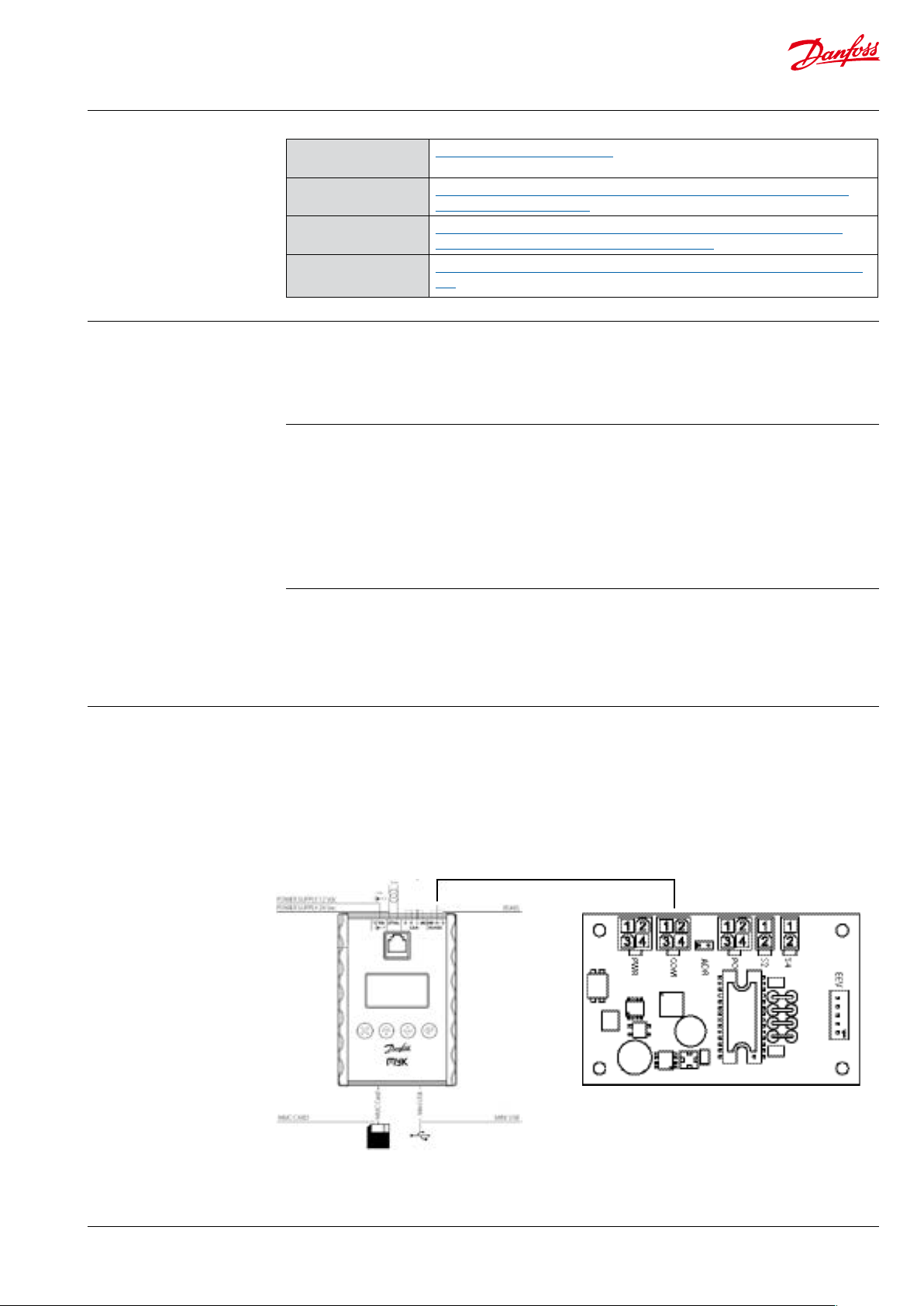
The MyK needs to be connected to a power
supply. Three options are available for this, it can
run either on a 12 V DC supply, a 24 V AC supply, or
it can be powered through the USB connection.
Modbus connection
ESC Up Down Ent er
First create a folder on the SD/MMC card, the
name of the folder must be 8 characters or less.
Then copy the two les into the folder. The SD/
MMC card can now be inserted into the MyK.
The MyK is connected to the EIM through the
modbus port (RS485), which is wired to the KM5
connector on the EIM.
D+ is connected to KM5,2
D- is connected to KM5,3
GND is connected to KM5,1
© Danfoss A/S (AC-MCI/sw), 2014-03 DKRCC.PS.RQ0.C2.02 / 520H8422
EIM 316 / 336
3
Page 4

Manual EIM 316/336 interface application for setup and conguration of MMIMyK
5. Starting the
application
Setting up the MYK to
specic EIM 336 unit
address.
The MyK will startup in its Bios menu if no
application has previously been loaded. From
this menu it is possible to load the applications
that are stored on the MyK, either in its internal
or external memory. Please refer also to the
MMIMyK software download guide.
Select Application – Appl.Load, then select the
disc that the application is stored on, 0:/ (internal
memory) or 1:/ (SD/MMC card). Select the folder
If the MyK does not recognize that it is connected to an EIM 336, it will beep to indicate
that it is in alarm.
On the main screen press enter and go to
“Parameters-> MyK setup-> System”.
Under “Active EIM Addr”, set the correct ID of
the EIM 336 you want to connect to. Under
“Serial baud rate (MB)” set the baud rate to the
containing the application and press the enter
button. The application should load automatically and will startup after a few seconds.
The next time the MyK is powered, it will start the
application automatically. To enter the bios menu
again, press the Esc and enter buttons at the same
time, and keep them pressed for a few seconds,
until the MyK enters the bios menu. From here it is
possible to load another application.
correct baud rate (default for EIM is 192 i.e. 19200
Baud) then after set the correct serial settings
under “Serial settings (MB)”, (default value for EIM
336 is 8E1 i.e. 8 data bits, even parity and 1 stop
bit). The MyK should now able to connect with
the EIM 336.
6. Using the
application
6.1 The main screen
The main screen shows the current superheat (SH)
and opening degree (OD) in large characters.
If the main switch is o, this will be shown with
the characters OFF in large characters in the
upper right corner. If the main switch is on, the
currently active superheat reference is shown in
the upper right corner instead.
If an alarm is present, this is indicated by the
word “ALARM” to the right of the opening
degree. If the unit is in manual control mode, this
is indicated with the word “MAN”.
Pressing enter will give access to the main menu.
Pressing escape will give access to the alarm screen.
4
DKRCC.PS.RQ0.C2.02 / 520H8 422
© Danfoss A/S (AC-MCI/sw), 2014-03
Page 5

Manual EIM 316/336 interface application for setup and conguration of MMIMyK
6. Using the
application
(continued)
6.2 Alarm screen
The alarm screen shows the alarms that have still
not been acknowledged. If more than one alarm
is active or has not been acknowledged, pressing
the up or down button will display the next or
previous alarm. Pressing the escape button for
two seconds will acknowledge the alarm and exit
the alarm screen. Pressing the escape button
6.3 The main menu
The main menu gives access to all the parameters and functions of the application. Navigation
is generally done by using the up or down
Main menu
|-----Login
|-----Parameters (see Parameters)
|-----Manual Control
|-----Readout
| |-----Overview
|-----Service
| |-----User2Factory
| |-----Factory2User
|-----Service Info
| |-----Software Info
| |-----Product Info
|-----Alarm
|-----Read Alarm
|-----Active Alarms
|-----Reset Alarms
briey will exit to the main screen without
acknowledging the alarm.
If an alarm becomes active the buzzer will sound
until it has been acknowledged. The alarm can
be muted by pressing the Esc button (or any of
the other buttons).
buttons to select a menu or function, and then
pressing the ok button to enter the menu or
function screen. Pressing escape will change the
screen to the previous menu or function screen.
6.4 Login
The login screen can be used to change the user
level. The default user level is level 0 which
means that no login is required. This user level
gives access to the most basic parameters, that
would be used on a daily basis. Some parameters
require a high user level, in order to be accessed,
see the parameter list for reference (Level). The
access code consists of a 4 digit code. When
entering the login screen the rst digit is
selected. Pressing up or down increases or
© Danfoss A/S (AC-MCI/sw), 2014-03 DKRCC.PS.RQ0.C2.02 / 520H8422
decreases the value of the selected digit.
Pressing enter, saves the digit and advances the
cursor to the next digit. Pressing the left or right
buttons, moves between the digits. When
pressing enter while the last digit is selected, the
access code is checked. If it is not correct, the
code is deleted and a new code can be entered.
If it is accepted, the access level changes and the
main menu is displayed. In the 2nd row from the
top, the current access level is visible.
5
Page 6

Manual EIM 316/336 interface application for setup and conguration of MMIMyK
6.5 Parameters
This is a list of the available parameters of the
MyK application. The parameters in the Control,
Regulation and Setup menus, are settings of the
Group1 Group2 Parameter Description Min Max Default Units Level Notes
Control 0
Reg Control 0
Regulation 0
SH Control 0
MOP 1
Defrost 1
Te Control 1
External sensors 3
connected EIM. If no EIM is connected, “---” is
r12 Main switch 0 1 0 0 OFF;ON
o18 Manl control 0 1 0 1 OFF;MAN
o45 Manual OD % 0 100/480 0 %/step 1 Used when the o18 Manual
tst Startup time 0 1800 0 s 2
SOD Startup OD 0 100 0 % 2
OOD OD while OFF 0 100 0 % 2
RAL Reset alarm 0 1 0 0 OFF;ON
n09 Max superheat 2.0 20.0 16. 0 K 0
n10 Min superheat 1.0 20.0 4.0 K 0
TSH Tn SH 10 1800 600 1
n22 SH close 0 16.0 0.5 K 1
SHL SH Low 3.0 20.0 6.0 K 2
SHH SH High 8.0 40.0 16.0 K 2
GaH Gain High 0.5 50.0 1.0 2
GaL Gain Low 0.1 50.0 12. 5 2
TaH Tau H igh 10 600 45 2
TaL Tau L ow 10 600 110 2
Aph Alpha 15 600 130 1
n20 KpT0 -1.0 20.0 -1.0 2
CoS Comp Speed 0.0 100.0 0.0 3
n09 Dyn max superheat 2.0 20.0 16.0 K 0
n10 Dyn min superheat 1.0 20.0 4.0 K 0
TSH Dyn Tn SH 10 1800 600 1
Aph Dyn Alpha 15 600 130 1
n11 MOP 0.0 200 13.7 bar 1
DMO Di MOP -20.0 0.0 0.0 bar 2
KpM Kp MOP 0.5 10.0 0.5 2
TnM Tn Mop 30 600 180 2
DeA Def Activate 0 1 0 1 OFF;ON
DHO Def Hold OD 0 100 30 % 2
DH1 Def Hold Ti 1 0 32000 120 s 2
DH2 Def Hold Ti 2 0 32000 60 s 2
DDO Dyn def hold OD 0 100 30 % 3
ter Te Reference -200.0 200.0 0.0 °C 1
KpT Kp Te 0.5 10 1 2
TnT Tn Te 30 600 60 2
PEV EvapPress P0 0 32000 0 bar 3
TS2 S2 temp -200.0 200.0 0.0 °C 3
TS4 S4 Air temp -200.0 200.0 0.0 °C 3
displayed instead of the value. The MyK Setup
and Password menus relate to the MyK application itself. Please refer to the EIM manual for a
description of the parameters concerning the
setup of the EIM.
Control is set to 1.
0%/0 step = fully closed,
100%/480 step = fully open.
% is chosen by default.
See “manual OD as steps”
for changing to step.
6
DKRCC.PS.RQ0.C2.02 / 520H8 422
© Danfoss A/S (AC-MCI/sw), 2014-03
Page 7

Manual EIM 316/336 interface application for setup and conguration of MMIMyK
6.5 Parameters (continued)
Group1 Group2 Parameter Description Min Max Default Units Level Notes
LOC 2
LTR LOC Trig 0 100 95 % 2
LRe LOC Reset 0 100 85 % 2
LTm LOC Timer 0 7200 3600 s 2
LST LOC SH Trig 0.0 50.0 20.0 K 2
Setup 0
Modbus 3
o03 Unit Addr 1 240 165 3
UA2 Unit Addr 2 1 240 164 3
MBa MB Baud 0 2 1 3 9 6;192; 384
MPa MB Parity 0 2 2 3 NO;ODD;EVEN
MSB MB StopB 1 2 1 3 --;1;2
Valve 2
MST Max steps 100 1000 384 3
MSS Max steps/sec 5 300 31 3
BKS Start backlash 1 100 10 % 2
BKL Backlash 0 100 20 2
COD Comp. dir. 1 2 1 3 UP;DOWN
MCU Motor current 0 300 150 3
Regfrigerant 2
RFG Refrigerant 0 37 23 2 1 : R12
RF1 Rfg. fac. A1 8000 12000 10428 3
RF2 Rfg. fac. A2 -4000 -1000 -2255 3
RF3 Rfg. fac. A3 1000 3000 2557 3
Sensors 2
r09 Adjust S2 -10.0 10.0 0.0 K 2
o20 Min transducer
press
o21 Max transducer
press
System 0
LBO Limited list (BO) 0 1 0 0 OFF;ON
HWM HW main switch 0 1 0 2 OFF;ON
F2U Factory to user 0 1 0 3 OFF;ON
U2F User to factory 0 1 0 3 OFF;ON
TSA Sampling time 1 10 1 3
MOS Manual OD as
steps
MyK Setup 0
System 0
add Active EIM Addr 0 254 165 0
bAU Serial baudrate 0 8 6 MB 0 0;12;24; 48; 96;14 4;192;288;38 4
COM Serial settings 0 2 1 MB 0 8N1;8E1;8N2
Passwords 1
System 1
L01 Level 1 psswd 0 9999 1000 1
L02 Level 2 psswd 0 9999 2000 2
L03 Level 3 psswd 0 9999 3000 3
0 1.0 0.0 Bar
(abs)
1 200 0.0 Bar
(abs)
0 1 0 3 Enable the manual OD in o45 to be
2 : R22
3 : R134a
4 : R502
5 : R717
6 : R13
7 : R13b1
8 : R23
9 : R500
10 : R503
11 : R114
12 : R142b
13 : User D
2
2
entered as halfsteps.
14 : R32
15 : R227
16 : R401A
17 : R507
18 : R402A
19 : R404A
20 : R407C
21 : R407A
22 : R407B
23 : R410A
24 : R170
25 : R290
26 : R600
27 : R600a
28 : R744
29 : R1270
30 : R417A
31 : R422A
32 : R413A
33 : R422D
34 : R427A
35 : R438A
36 : Opteon
XP10
37 : R407F
© Danfoss A/S (AC-MCI/sw), 2014-03 DKRCC.PS.RQ0.C2.02 / 520H8422
7
Page 8

Manual EIM 316/336 interface application for setup and conguration of MMIMyK
6.6 Manual control
The valve can be opened and closed by manually
setting an opening degree, while the controller is in
manual control mode. It is possible to set the
controller in manual control mode, by pressing
enter on the manual control screen. This selects the
manual control setting. Pressing enter again, makes
it possible to toggle the manual control setting on
or o, by pressing the up or down buttons.
After setting the manual control mode to on,
press enter to accept the change. It is now
possible to select the manual opening degree,
by pressing the down button and pressing enter.
Using the up or down buttons, the wanted
opening degree can now be set. Pressing enter
accepts the opening degree, and the valve will
open or close to the selected opening degree.
6.7 Readouts
The readout screen shows some of the important
readout values, read from the controller.
This includes the current superheat, superheat
reference, current opening degree etc.
8
DKRCC.PS.RQ0.C2.02 / 520H8 422
© Danfoss A/S (AC-MCI/sw), 2014-03
Page 9

Manual EIM 316/336 interface application for setup and conguration of MMIMyK
6.8 Service functions
Two service functions are available, resetting to
factory default settings, and setting factory
default settings.
The User2Factory function will copy the current
settings, into the eeprom and save them as
factory defaults. This means that if a factory reset
is performed, these are the settings that will be
used.
The Factory2User function will overwrite the
current settings, with settings that are stored in
the eeprom.
6.9 Service info screens
The service info screens display dierent
information about the application. Software info
displays the name, software version and date of
the application. It also displays the bios version
number and date of the MyK itself.
The product info screen displays the software
version number and order number of the
connected EIM.
© Danfoss A/S (AC-MCI/sw), 2014-03 DKRCC.PS.RQ0.C2.02 / 520H8422
9
Page 10

Manual EIM 316/336 interface application for setup and conguration of MMIMyK
6.1 0 A l a r m
The read alarm screen displays a list of the
currently active alarms reported from the
connected EIM. The status of 8 dierent alarms
are reported back from the EIM. A 0 (zero) means
that the alarm is not active, a 1 means that the
current alarm is active.
The active alarms screen displays details of the
currently unacknowledged alarms. If more than
one alarm has not been acknowledged, pressing
the up or down buttons scrolls between them.
If all alarms have been acknowledged or if no
alarms are present, the text “No alarms” is
displayed instead.
10
DKRCC.PS.RQ0.C2.02 / 520H8 422
© Danfoss A/S (AC-MCI/sw), 2014-03
 Loading...