

ENGINEERING
R
80G8127
Battery
Pressure
80 mm / 3.15 in
TOMORROW
Installation guide
Electronic superheat controller
Type EIM 316 / 336 / 365
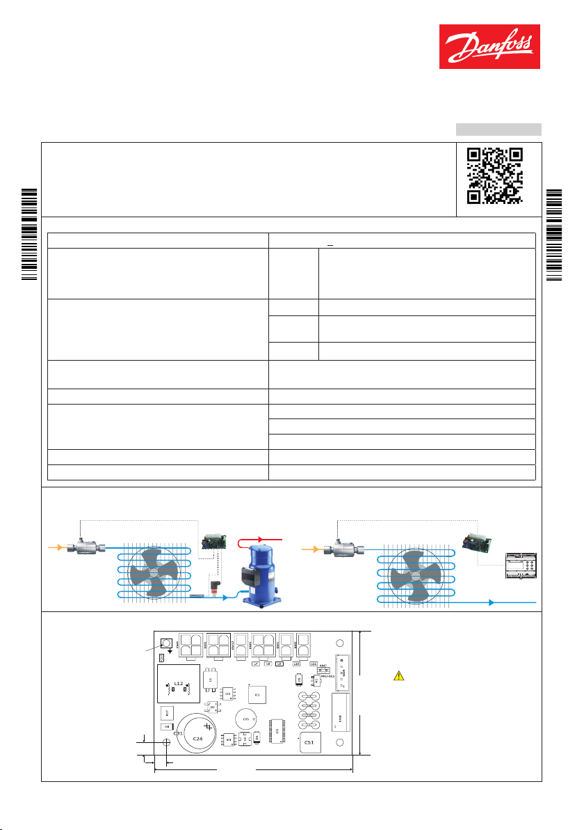
Introduction
Superheat controller EIM series is for use where superheat must be accurately
controlled, typically in commercial air conditioning, heat pumps, commercial
080 R9347
refrigeration and food retailing applications.
Reference: For details please see EIM data sheet.
Technical specifications
Supply voltage 24 V AC / DC (+ 15%), 50 / 60 Hz, 15 VA / 8 W, Class II isolation
Idle
Power consumption
Input signals
For the EMC compliance, sensor cable length must be
< 3 m / 118 in. For longer sensor cable, a ferrite bead
should be used.
Valve support
operating
Po 0.5 - 4.5 Vdc ratiometric pressure sensor i.e AKS 32R
S2 PT1000 (measuring range -60 – 120 °C /
S4 PT1000 or digital input from external contact
EIM 365: ETS 6 / ETS / ETS Colibri, KVS / KVS Colibri, CCM, CCMT
EIM 316/336: ETS 6
Data communication RS 485 – MODBUS RTU (Not terminated internally)
Storage : -34 – 71 °C / -30 – 160 °F
Environment
Operating : -25 – 60 °C / -13 – 140 °F
Humidity : < 95% RH, non condensing
Battery backup (Only for EIM 365) 18 - 28 V DC, > 49 VmAh
Operation Standalone or via MODBUS data communication
Applications
1. Superheat controller: standalone 2. Valve driver
Max. 10 mA @ 24 V DC (EIM 316 & 336)/ 25mA @
24V DC (EIM 365)
Max. 150 mA @ 24 V DC (EIM 316 & 336)/ 625mA @
24V DC (EIM 365)
-76 – 248 °F)
English
080 R9347
More info
EIM 316 / 335 / 336
© Danfoss | DCS (sb) | 2020.02
ETS Colibri®
ø 3 mm /
0.118 in
GND
5 mm / 0.2 in
S2 Pe
Power
1
2
4
3
5 mm / 0.2 in
BAckup
MODbus
11131
3
sensor
4
2
4
Danfoss
Danfoss
64-8040
R64-8040
ETS Colibri®
S2
S4
122
2
2
Danfoss
Reference signal
via MODBUS
Danfoss
R64-8041
Note:
S2 - Temperature sensor or DI
S4 - Temperature sensor
Weight : 40 gm
50 mm / 1.97 in
AN327425434124en -000201 | 1
Danfoss
80G165.10
PWR
COM
PWR
COM
Installation warnings
Colibri®
- Recommended mounting position: vertical
- Installation must comply with local standards and legislation
- Before working on the electrical connections, disconnect the device from the main power supply
- Before carrying out any maintenance operations on the device, disconnect all electrical connections
- For safety reasons the appliance must be fitted inside an electrical panel with no live parts accessible
- Do not expose the device to continuous water sprays or to a relative humidity greater than 90%
- Avoid exposure to corrosive or pollutant gases, natural elements, environments where explosives or
mixes of flammable gases are present, dust, strong vibrations or shock, large and rapid fluctuations
in ambient temperature that might cause condensation in combination with high humidity, strong
magnetic and/or radio interference (e.g. transmitting antennae).
- When connecting loads be aware of the maximum current for each relay and connector
- Use cable ends suitable for the corresponding connectors. After tightening connector screws, tug the
cables gently to check their tightness.
- Use appropriate data communication cables. Refer to the EIM data sheet for the kind of cable to be
used and setup recommendations.
- Minimize the length of probe and digital input cables as much as possible, and avoid spiral
routes around power devices. Separate from inductive loads and power cables to avoid possible
electromagnetic noises.
- Avoid touching or nearly touching the electronic components fitted on the board to avoid
electrostatic discharges.
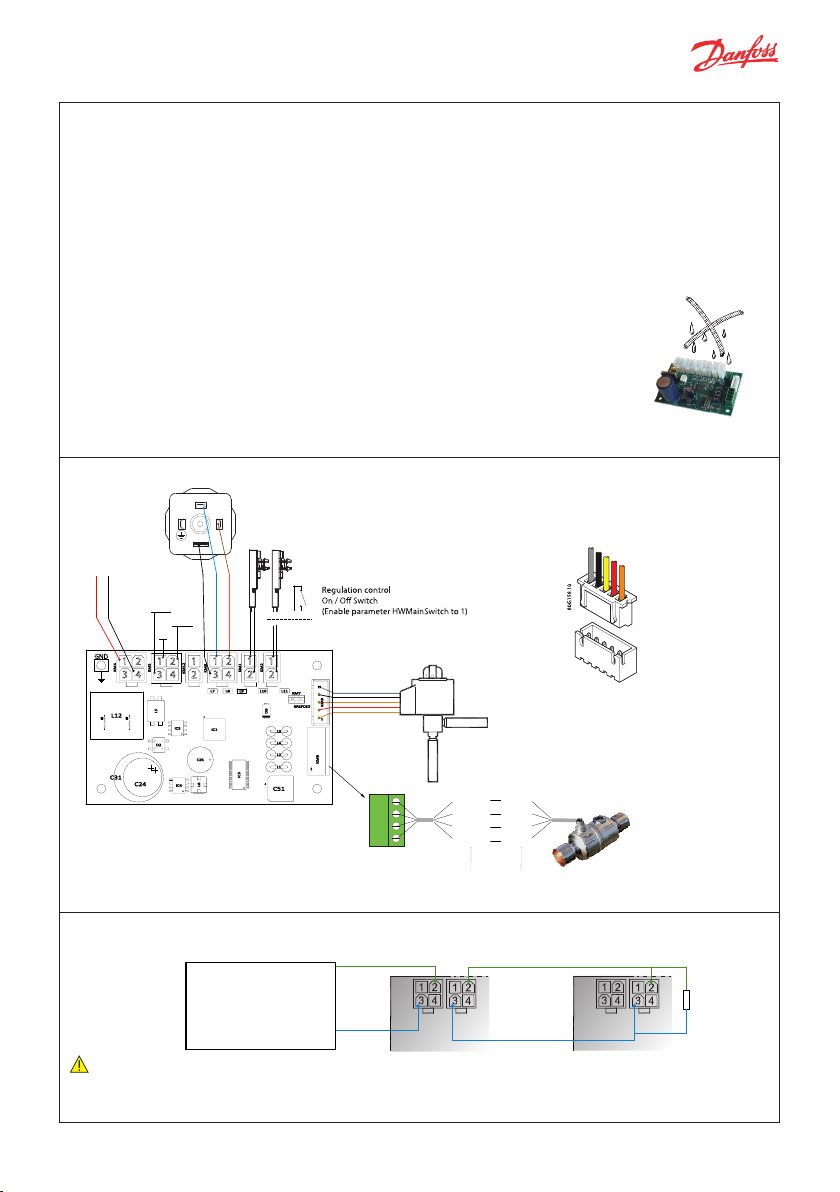
Connection overview
TxD -
3
2
Temperature sensors
3
PT 1000
i.e. AKS 11
1
TxD
+
D
11 1
1
12
2
3
2 2
44
2
ETS 6 with
JST-XHP 5 connector
JST XHP-5 CONNECTOR
Pressure transmitter
Ratiometric 0.5 – 4.5 V
i.e. AKS 32R
Power Supply
24 V AC or DC
+
-
MODBUS to master
controller
GND
1
3
2
4
Connector on
ETS 6 coil
Connector on
EIM 336 controller
MODBUS connection overview
MODBUS in Daisy Chain
Note:
• If two EIMs are connected remember to remove the addressing jumper on one of the EIMs
• MODBUS transmission lines usually require termination resistors, especially for longer cable lengths
© Danfoss | DCS (sb) | 2020.02
Black
B2
B1
A2
A1
EIM slave 1
RS485 (+)
Master controller
RS485 (-)
Red
Yellow
Orange
ETS 6 valve
Green
Red
Black
White
ETS / KVS
RS485 (+)
RS485 (-)
EIM slave 2
R = 120 Ohm
Min. 0.25 W
AN327425434124en -000201 | 2

80G159.10
11.6 mm
10.7 mm
8.5 mm
0.33 in
6.3 mm
0.25 in
80G161.10
10.6 mm
Mating connectors for EIM Controller
80G163.10
Type Molex Mini-Fit Jr.™
4 WAY MINI-FIT RECEPTACLE
Molex 39-01-2040 or similar
0.46 in
0.42 in
80G160.10
Connector kit for 5x EIM controller 080G1601
Quick guide for parameter selection
A. Setting controller in Superheat
control mode.
Make sure that r12 = 0 (OFF) and change the settings.
The setting will depends on the system requirement.
Enabling Regulation control ON / Off switch (optional)
HwMainSwitch = 1 (default is 0, i.e S4 sensor).
For standalone configuration it is recommended to
enable Regulation control ON / Off switch in order to
control start/stop regulation when needed, otherwise
the controller will start regulating when controller is
powered up.
Select Refrigerant
o30 = 1 – 49
Select valve setting
For EIM 365, first select Proper Danfoss valve t ype
(PNU 3002). For EIM 316/336, the default valve type is
ETS 6.
n37 = 384 x 10 micro step (3840 micro steps = 480 half
steps)
n38 = Max. steps / sec
Define pressure sensor range in bar absolute (x10)
o20 = Min. Transducer pressure
o21 = Max. Transducer pressure
Define min/max superheat
Define SH control type:
SH Mode : 1 = MSS , 2= LoadAP (PNU 3026 )
n10 = min. superheat reference
n09 = max. superheat reference
For fixed superheat define n09 = n10
Define MOP (optional)
n11 = maximum operating pressure
2 WAY MINI-FIT RECEPTACLE
Molex 39-01-2020 or similar
0.42 in
RECEPT CONTACT
24-18AWG Molex
39-00-0039 or similar
80G162.10
Set force opening of the valve (optional)
Start-up OD% (PNU 3015)
Start-up time (PNU 3017)
For EIM 365, Startup mode P-control has been enabled as
default. for detail check startup mode parameter
(PNU 64322).
To start the superheat control
Set r12= ON
B. Setting controller in valve driver mo de
using MODBUS signal
Make sure that r12 = 0 (OFF) and change the
settings so they fit to their application:
Select Application mode
o18 (PNU 2075 )= 1 i.e Manual control
Select valve setting (optional)
For EIM 365, first select Proper Danfoss valve t ype
(PNU 3002). For EIM 316/336, the default valve type is
ETS 6.
n37 = 384 x 10 micro step (3840 micro steps = 480 half
steps).
n38 = Max steps / sec
Select manual opening degree
o45 Manual OD % (PNU 2064)
0 = fully closed, 100 = fully open
By changing parameter o45 Manual OD, the valve will
move accordingly regardless of r12 parameter value.
© Danfoss | DCS (sb) | 2020.02
AN327425434124en -000201 | 3

EIM – Commonly used parameter identification
Group PNU Param-
Regulation
117 r12 Main switch 0 1 0
Control
2075 o18 Manl control 0 1 0
2064 o45 Ma nual OD 0 100 0 %
3026 n21 SH Mode 1 2 2
Super Hea t
3015 n09 Max. superheat 20 200 90 K
Control
3021 n10 Min. superheat 10 200 40 K
3032 n37 Max steps 10 0
3033 n38 Max steps / sec 10 400 16
Valve
(Valve
selec tion
valid
for EIM
365, FOR
EIM 316
3002
and 336
default i s
ETS 6 )
Refriger-
2551 o30 Refrigerant 1 49
ant
113 r09 Adjust S2 -100 100 0 K
2033 o21
Sensors
2034 o20
Note :
• “e2” is the value stored in EEPROM. “W” is writing to the register possible “*10” is scale of the parameter.
• For detail parameter list, refer to the EIM datasheet.
• Default Modbus setting 19200 8E1.
Symbol ic
eter
name
n03 Valv e Type
Max. transducer pressure
Min. transducer
pressure
Min. Max. Default Units e2 W *10 Description
With this setting the regulation can be started
and stopped. This can also be accomplished with
ü
the external hardware main switch.
0 = Superheat control, 1 = Manual control
ü
Manual opening degree for manual control.
Used when the o18 Manual Control is set
ü
to 1 (fully closed = 0% , fully open = 100%).
1: MSS, 2: Load AP
Maximum superheat reference setting
Minimum superheat reference setting
Maximum number of steps
(384 x 10 microsteps = 480 half steps)
(Values in bracket is for EIM 316,336)
Steps per second
0 : ETS 12.5, ETS 25, KVS 15
1 : ETS 50, CCM 10, CCM 20, CCM30
2 : ETS 100, CCM 40
3 : ETS 250, KVS 42
4 : ETS 400
5 : User defined
6 : UKV, SKV, VKV, PKV
7 : ETS 6
8 : CCMT 2, CCMT 4, CCMT 8
9 : CTM16
10 : CCMT 24
11 : CCMT 30
12 : CMT 42
13 : CTR
14 : CCMT 0
15 : CCMT 1
16 : No valve sele cted
17 : ETS 12C, 24C, 25C, 50 C, 100C, KVS 2C, 3 C, 5C
0: None
1: R12
2: R22
3: R134a
4: R502
5: R717
6: R13
7: R13B1
8: R23
9: R500
10: R503
11: R114
12: R142b
13: User
14: R32
15:R227ea
16: R401A
S2 Offset adjustment
Maximum transducer pressure
(in bar absolute * 10)
Minimum transducer pressure
(in bar absolute * 10)
8000
(1000)
0 17 EIM 365: 16
10 600 16 0
-10 0 0
240
(384)
EIM 365: 0
EIM 316,
336: 23
bar
(abs.)
bar
(abs.)
ü ü
ü ü ü
ü ü ü
ü ü
ü ü
ü ü
ü ü
ü ü ü
ü ü ü
ü ü ü
17: R507A
18: R402A
19: R404A
20: R407C
21: R407A
22: R407B
23: R410A
24: R170
25: R290
26: R600
27: R600a
28: R744
29: R1270
30: R417A
31: R422A
32: R413A
33: R422D
Related products
Pressure transducer
AKS 32R, NSK BExx
Temperature sensor
AKS 21, AKS 11, ACCPBT
Programming key / display
MYK - EIM interfacer
Electric Expansion valve
ETS series
Backup power module
EKE 2U
34: R427A
35: R438A
36: R513A
37: R407F
38: R1234zeE
39: R1234yf
40: R448A
41: R449A
42: R452A
43: R450A
44: R452B
45: R454B
46: R1233zdE
47: R1234zeZ
48: R449B
49: R407H
© Danfoss | DCS (sb) | 2020.02
AN327425434124en -000201 | 4
 Loading...