

Page 1
MAKING MODERN LIVING POSSIBLE
Technical Information
EHPS Steering Valve
PVE Actuation Module
OSPCX CN Steering Unit
powersolutions.danfoss.com
Page 2

Technical Information EHPS Steering Valve PVE Actuation Module OSPCX CN Steering Unit
Revision history Table of revisions
Date Changed Rev
May 2015 Minor update EB
August 2014 EHPS type 2 section updated EA
July 2014 Converted to Danfoss layout DA
October 2009 Steering column deleted CA
May 2009 Note added BC
2 520L0521 • Rev EB • May 2015
Page 3

Technical Information
EHPS Steering Valve PVE Actuation Module OSPCX CN Steering Unit
Contents
A wide range of Steering Components
For hydrostatic steering systems Danfoss offers:................................................................................................................. 5
For electrohydraulic steering systems Danfoss offers:....................................................................................................... 6
Characteristic features for steering units:................................................................................................................................6
Characteristic features for electrohydraulic steering systems with OSPE and EHPS:.............................................. 6
Conversion factors........................................................................................................................................................................... 6
Survey of literature with technical data on Danfoss Steering Components...............................................................6
General
Electrohydraulic steering...............................................................................................................................................................7
Steering valve EHPS and electrical actuation module PVE for EHPS
Versions................................................................................................................................................................................................8
EHPS type 0, hydrostatic steering system:.........................................................................................................................8
EHPS type 1, Hydrostatic and Electrohydraulic Steering System:............................................................................. 9
EHPS type 2, hydrostatic and electrohydraulic steering system:............................................................................ 10
Functional options overview................................................................................................................................................11
EHPS type 0, 1 or 2 with flanged on priority valve OLS 320:.....................................................................................12
Function............................................................................................................................................................................................ 13
EHPS valve...................................................................................................................................................................................13
Neutral position................................................................................................................................................................... 14
Steering left...........................................................................................................................................................................15
PVES and PVED-CLS, electrical actuation.........................................................................................................................16
Closed loop control..................................................................................................................................................................17
Principle....................................................................................................................................................................................... 17
Inductive transducer, LVDT...................................................................................................................................................17
Integrated pulse width modulation...................................................................................................................................17
Technical data
EHPS....................................................................................................................................................................................................18
PVES.................................................................................................................................................................................................... 19
PVED-CLS...........................................................................................................................................................................................19
Hysteresis, PVES and PVED-CLS................................................................................................................................................ 19
PVES and PVED-CLS.......................................................................................................................................................................20
Installation PVED-CLS................................................................................................................................................................... 21
Variants
Variants of EHPS..............................................................................................................................................................................22
Dimensioning
Dimensioning steering system with EHPS steering valve...............................................................................................24
Technical characteristics
Directional spool - oil flow characteristic for spool 40/5................................................................................................. 26
Directional spool - cylinder flow characteristic for all directional spools..................................................................27
Pilot pressure relief valve: (P - T, Qp) characteristic...........................................................................................................27
Pressure drop P-EF for Danfoss EHPS valve..........................................................................................................................28
Pressure drop P-EF for OLS integrated in EHPS............................................................................................................. 28
Pressure drop P-EF for OLS 320 static priority valve flanged on EHPS..................................................................28
Dimensions
EHPS type 0, stand alone.............................................................................................................................................................29
EHPS type 1, stand alone.............................................................................................................................................................31
EHPS type 1, with PVG..................................................................................................................................................................33
EHPS type 1, with OLS 320..........................................................................................................................................................35
Hydraulic systems
EHPS type 0, stand alone and OSPCX CN steering unit....................................................................................................37
EHPS type 1, stand alone, OSPCX CN steering unit and PVRES joystick.....................................................................37
EHPS type 1 with PVG 32, OSPCX CN pilot steering unit and PVRES joystick...........................................................38
System safety
Emergency steering...................................................................................................................................................................... 39
520L0521 • Rev EB • May 2015 3
Page 4

Technical Information EHPS Steering Valve PVE Actuation Module OSPCX CN Steering Unit
Contents
EHPS type 1 and type 2, prioritizing input signal...............................................................................................................40
Fault monitoring.......................................................................................................................................................................40
Passive fault monitoring........................................................................................................................................................ 41
Safety considerations..............................................................................................................................................................41
Safety considerations..............................................................................................................................................................42
On-road operation..............................................................................................................................................................42
Order specification
Order specification for EHPS and PVE.....................................................................................................................................43
Steering unit OSPCX CN
Version............................................................................................................................................................................................... 44
Closed center............................................................................................................................................................................. 44
Code numbers and weights
Order specification
Specification table for non catalogue numbers of Danfoss OSPCX CN steering units.........................................46
Technical data
Common data..................................................................................................................................................................................47
Manual steering pressure............................................................................................................................................................47
Displacement, flow and pressure.............................................................................................................................................47
Dimensions
Dimensions OSPCX CN.................................................................................................................................................................48
4 520L0521 • Rev EB • May 2015
Page 5
Technical Information
EHPS Steering Valve PVE Actuation Module OSPCX CN Steering Unit
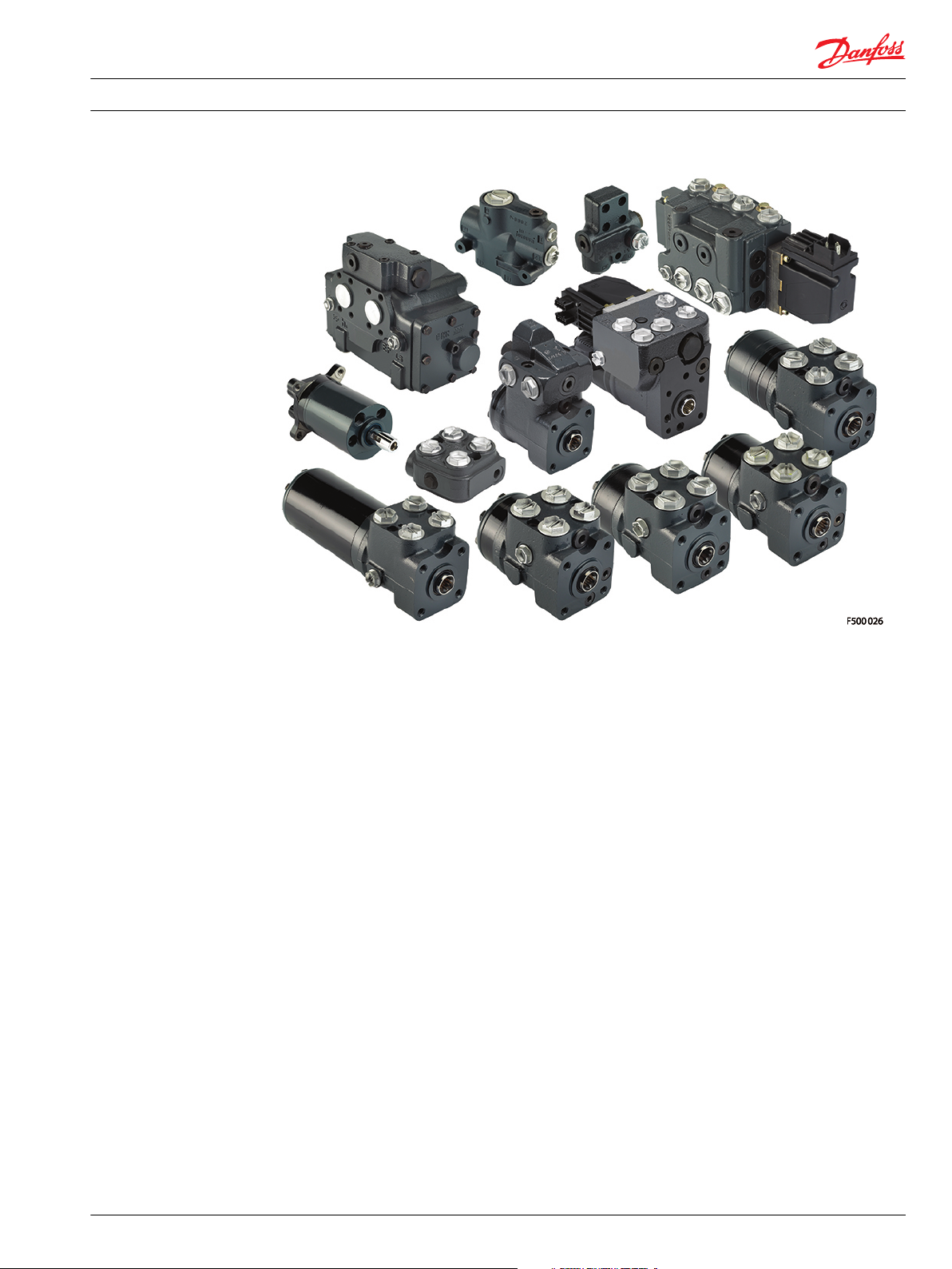
A wide range of Steering Components
Danfoss is one of the largest producers in the world of steering components for hydrostatic steering
systems on off-road vehicles. Danfoss offers steering solutions both at component and system levels. Our
product range makes it possible to cover applications of all types - ranging from ordinary 2-wheel
steering (also known as Ackermann steering) to articulated steering, automatic steering (e.g. by sensor)
and remote controlled steering via satellite. We can offer more than 1,800 different steering units and 250
different priority valves categorized in types, variants and sizes.
For hydrostatic steering systems Danfoss offers:
Mini steering units with displacements from 32 to 100 cm3/rev [1.95 to 6.10 in3/rev], flow up to 20
•
l/min [5.28 US gal/min], steering pressure up to 140 bar [2030 psi].
Steering units with displacements from 40 to 1200 cm3/rev [2.44 to 73.2 in3/rev], flow up to 100 l/min
•
[26.4 US gaL/min, steering pressure up to 240 bar [3481 psi].
Priority valves for rated flows at 40, 80, 120, 160 and 320 l/min [10.6, 21.1, 31.7, 42.3 and 84.5 US gal/
•
min], pressure up to 350 bar [5076 psi].
Pilot operated flow-amplifiers with amplification factors of 4, 5, 8, 10 or 20 for rated oil flows of 240
•
and 400 l/min [63.4 and 105.7 US gal/min], steering pressure up to 210 bar [3045 psi].
Pilot operated steering valve with steering flow up to 100 l/min [26.4 US gal/min], steering pressure
•
up to 250 bar [3625 psi] and with integrated priority valve for pump flow up to 120 l/min [31.7 US gal/
min].
520L0521 • Rev EB • May 2015 5
Page 6

Technical Information
EHPS Steering Valve PVE Actuation Module OSPCX CN Steering Unit
A wide range of Steering Components
For electrohydraulic steering systems Danfoss offers:
Pilot operated steering valves (pilot operated by hydrostatic steering unit or by electrical signal) with
•
steering flows up to 100 l/min [26.4 US gal/min], steering pressure up to 250 bar [3625 psi].
Steering units with integrated electrical operated steering valve with steering flow up to 50 l/min
•
[13.2 US gal/min], steering pressure up to 210 bar [3045 psi].
Characteristic features for steering units:
Low steering torque: From 0.5 N•m to 3 N•m in normal steering situations
•
Low noise level
•
Low pressure drop
•
Many types available: Open center Non-reaction, Open center Reaction, Power Beyond, Closed center
•
Non-reaction, Load Sensing, Load Sensing Reaction
One or more built-in valve functions: relief valve, shock valves, suction valves, non-return valve in P-
•
line and in LS-line
Optional port connections (according to ISO, SAE or DIN standards)
•
Characteristic features for electrohydraulic steering systems with OSPE and EHPS:
Possibility of GPS, row sensor, variable steering ratio and joystick steering
•
The possibility of manual steering even on very heavy vehicles
•
EHPS: High steering pressure requiring smaller cylinders and flow
•
EHPS: Low pilot pressure and flow giving extremely low noise in the cabin
•
EHPS: Can be combined with Danfoss PVG 32 proportional valve
•
Conversion factors
1 N•m = [8.851 lbf•in] 1 l = [0.264 US gal]
1 N = [0.2248 lbf] 1 bar = [14.5 psi]
1 mm = [0.0394 in] °F = [1.8°C + 32]
1 cm3 = [0.061 in3]
Survey of literature with technical data on Danfoss Steering Components
Detailed data on all Danfoss steering components and accessories can be found in our steering
component catalogues, which is divided in to the following individual sub catalogues:
General information Steering components
Technical data on mini steering units OSPM
Technical data on open center, and closed center steering units OSPB, OSPC, and OSPD
Technical data on load sensing steering units, priority valves and flow
amplifiers
Technical data on hydraulic and electrohydraulic pilot operated steering
valves, electrical actuation modules and appropriate steering units.
Technical data on combined steering unit/electrohydraulic steering valves
and steering wheel sensors
Technical data on load sensing steering unit with amplification OSPU
For technical information on individual variants, please contact the Danfoss Sales Organization.
OSPB, OSPC, OSPF, OSPD, OSPL,
OSPBX, OSPLX, OVPL, OLS and OSQ
EHPS, EHPS w. OLS 320, PVE for EHPS
and OSPCX
OSPE and SASA
6 520L0521 • Rev EB • May 2015
Page 7
Technical Information EHPS Steering Valve PVE Actuation Module OSPCX CN Steering Unit
General
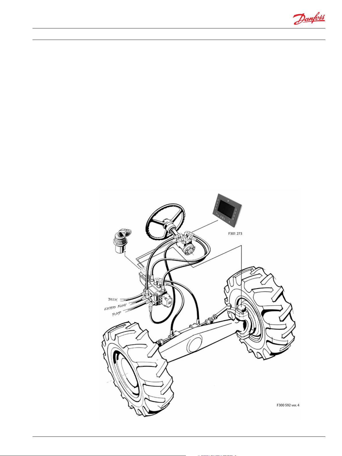
Electrohydraulic steering
On loaders, large forklift trucks, dumpers, heavy tractors, combine harvesters, maize harvesters and other
similar machines there is often need for electrically actuated steering either in the form of a joystick, or
fully automatic.
For this purpose Danfoss has developed a pilot operated steering valve type EHPS (Electro Hydraulic
Power Steering).
A basic system (type 0) consists of a pilot steering unit as the signal source and an EHPS valve block which
controls oil flow to the steering cylinders proportional to the pilot flow.
The system can be extended to include an electrical actuator so that, as an alternative, it becomes
possible to steer with a joystick (EHPS type 1).
Alternatively the actuator can be an electrical programmable module (PVED-CLS) to give much more
different steering features such like, variable steering ratio, speed dependent steering ratio, steering
wheel drift compensation, active jerk force compensation and soft end stop. This system is called EHPS
type 2.
Electrohydraulic steering system
520L0521 • Rev EB • May 2015 7
Page 8
Steering
cylinger
150-567.10
OSP
Q
Q
EHPS valve
CL CR EHPS type 0
L
R
Ps
Ts
TLSPEF
P301 028
Technical Information EHPS Steering Valve PVE Actuation Module OSPCX CN Steering Unit
Steering valve EHPS and electrical actuation module PVE for EHPS
Versions
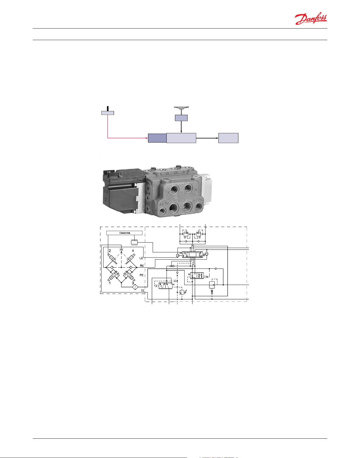
EHPS type 0, hydrostatic steering system:
EHPS Type 0 is a hydraulic steering system only with the EHPS valve acting as a pilot operated directional
valve. The steering unit type OSPCX CN acts as a pilot unit delivering oil at a low pressure and low flow.
The steering unit needs less displacement compared with an ordinary hydrostatic steering system. The
displacement can be optimized for emergency steering.
8 520L0521 • Rev EB • May 2015
Page 9
Steering
cylinger
Joystick
150-566.10
OSP
PVE
Q
Q
EHPS valve
PVES CL CR EHPS type 1
L
R
Ps
Ts
TLSPEF
P301 026
Technical Information EHPS Steering Valve PVE Actuation Module OSPCX CN Steering Unit
Steering valve EHPS and electrical actuation module PVE for EHPS
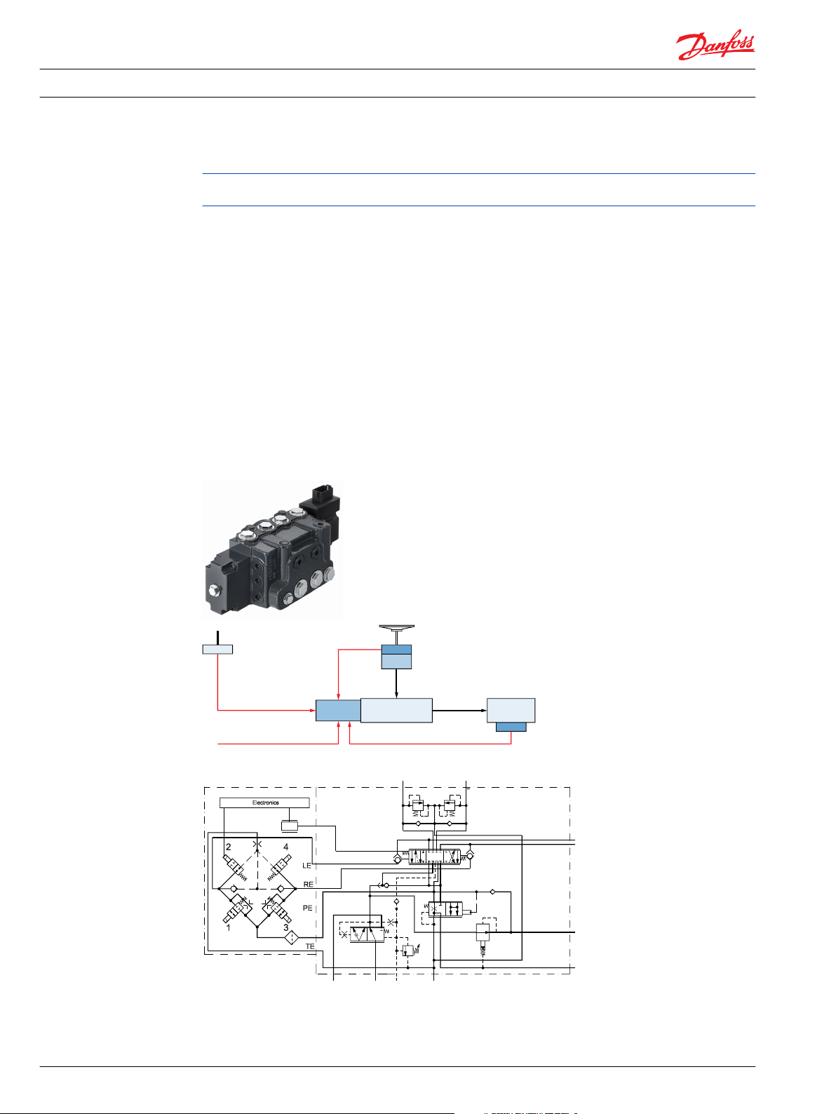
EHPS type 1, Hydrostatic and Electrohydraulic Steering System:
This system consists of an EHPS valve (type 0) equipped with an electrical module (PVES) for activating
the EHPS valve. There are 2 possibilities of steering: either hydraulic with the steering wheel (OSPCX CN)
or electrically using a signal from, for example, a joystick or a mini steering wheel. Input from the steering
wheel (OSPCX CN) will always have highest priority.
520L0521 • Rev EB • May 2015 9
Page 10
Steering
cylinger
Joystick
Steering Wheel Sensor
Vehicle Speed Position Seorn
150-565.12
OSP
CAN bus
Q
Q
PVED CLS
EHPS valve
SASA
PVED CLS CL CR EHPS type 2
L
R
Ps
Ts
TLSPEF
P301 027
Technical Information EHPS Steering Valve PVE Actuation Module OSPCX CN Steering Unit
Steering valve EHPS and electrical actuation module PVE for EHPS
EHPS type 2, hydrostatic and electrohydraulic steering system:
PVED-CL must not be promoted any longer. PVED-CL will be replaced by PVED-CLS by the end of 2014.
Please contact Danfoss Sales Organization for further details.
This system consists of an EHPS valve (type 0) equipped with an electrical programmable module (PVEDCLS) for activating the EHPS valve. There are many possibilities of steering:
With the steering wheel either pure hydraulic by help of the OSPCX CN steering unit or electrohydraulic
by help of the SASA steering wheel sensor placed between column and steering unit.
The EPHS can be controlled electrically also by using signals from, for example, GPS controller, row
censor, joystick or mini steering wheel.
Input from the steering wheel will always have highest priority.
With PVED-CLS the following steering features in electro hydraulic steer mode are possible:
Variable steering ratio
•
Speed dependent steering ratio
•
Steering wheel drift compensation
•
Active jerk force compensation
•
Soft end stop
•
10 520L0521 • Rev EB • May 2015
Page 11

Technical Information EHPS Steering Valve PVE Actuation Module OSPCX CN Steering Unit
Steering valve EHPS and electrical actuation module PVE for EHPS
Functional options overview
Section will be updated with PVED-CLS.
520L0521 • Rev EB • May 2015 11
Page 12
P301 025
EF
EF
L
R
Ps
Ts
LS
LS
P
P
OLS 320
T
CL CR
EHPS
type 0
Technical Information EHPS Steering Valve PVE Actuation Module OSPCX CN Steering Unit
Steering valve EHPS and electrical actuation module PVE for EHPS
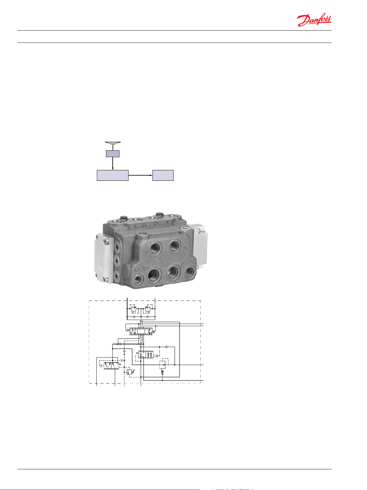
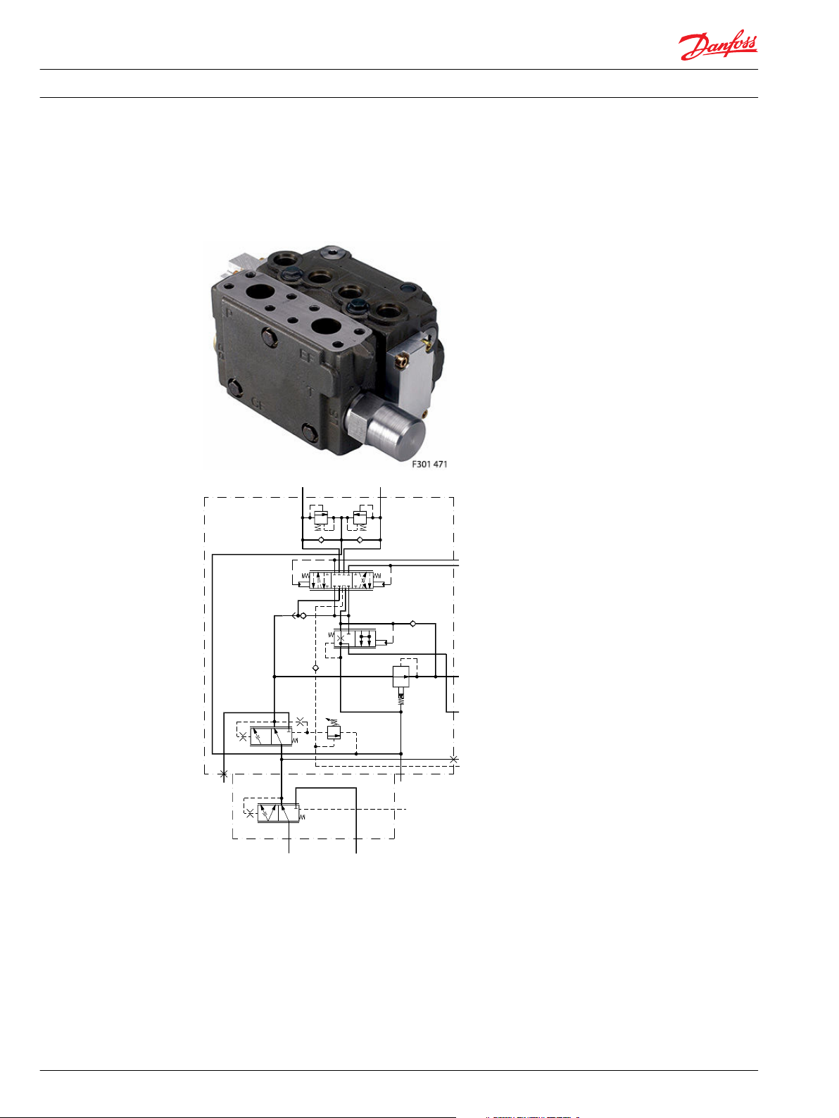
EHPS type 0, 1 or 2 with flanged on priority valve OLS 320:
EHPS sterring valve has build in priority valve, but for max. pump flow 120 l/min [31.7 US gal/min]. In
systems with EHPS and pump flow between 120 l/min [31.7 US gal/min] and 320 l/min [84.5 US gal/min] a
combination of EHPS and OLS 320 gives a good compact solution to reduce hosing and installation cost
compared with stand alone components.
12 520L0521 • Rev EB • May 2015
Page 13
P301 018
1
2
4
5
6
7
3
8
9
2
2
10
11
11
Technical Information
EHPS Steering Valve PVE Actuation Module OSPCX CN Steering Unit
Steering valve EHPS and electrical actuation module PVE for EHPS
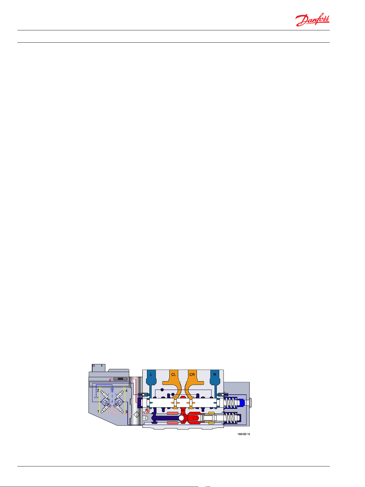
Function
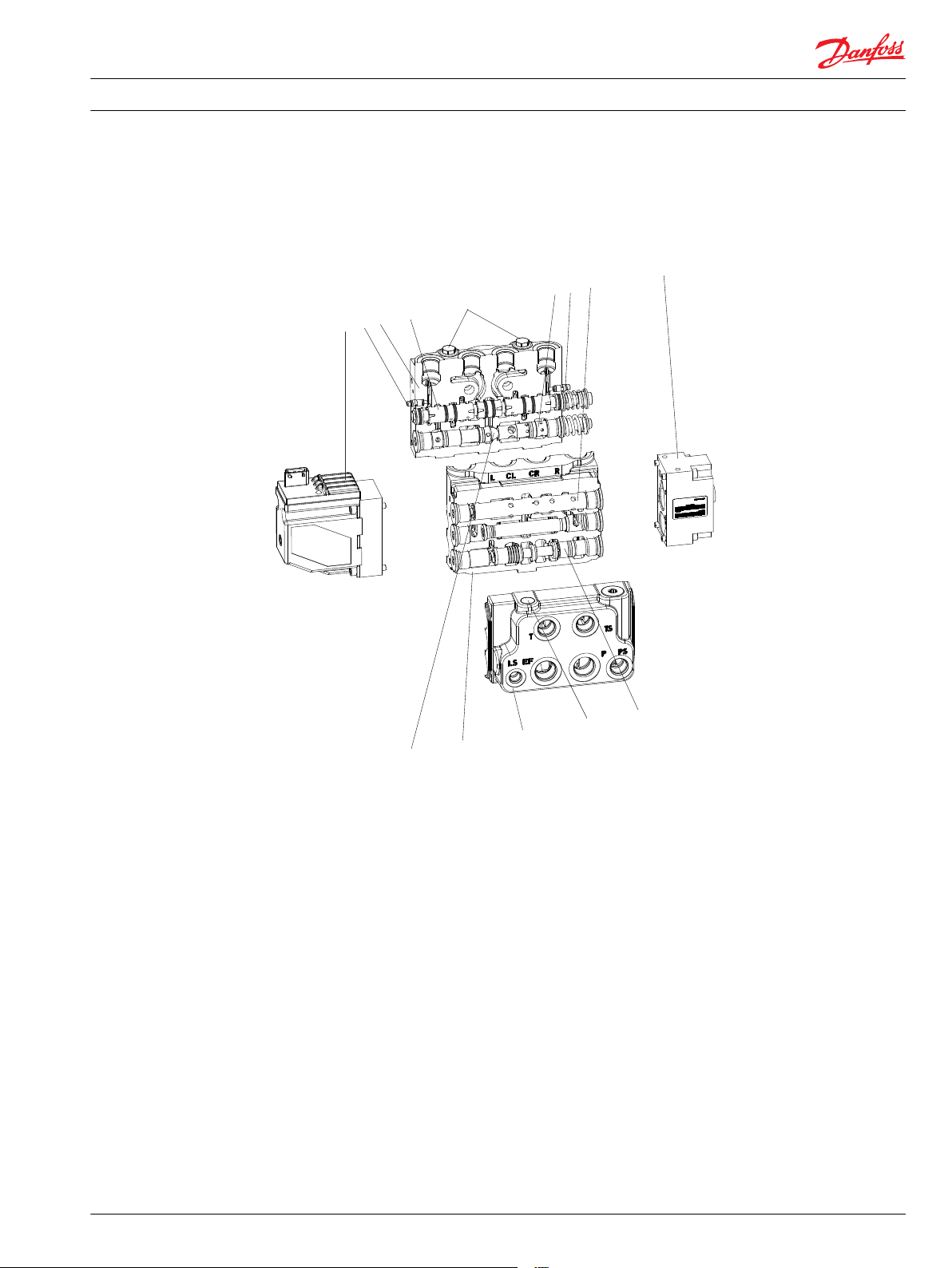
EHPS valve
The EHPS includes the following main components:
1.
Electrical actuation module
2. Housing
3. Directional spool
4. Shock and suction valve
5. Pilot pressure reduction valve for steering unit
6. Pilot pressure valve for electrical actuating module also called metering valve
7. Priority valve
8. Cover
9. Emergency steering valve
10. Pilot pressure relief valve
11. Shuttle valves
520L0521 • Rev EB • May 2015 13
Page 14
P301 020
Technical Information
EHPS Steering Valve PVE Actuation Module OSPCX CN Steering Unit
Steering valve EHPS and electrical actuation module PVE for EHPS
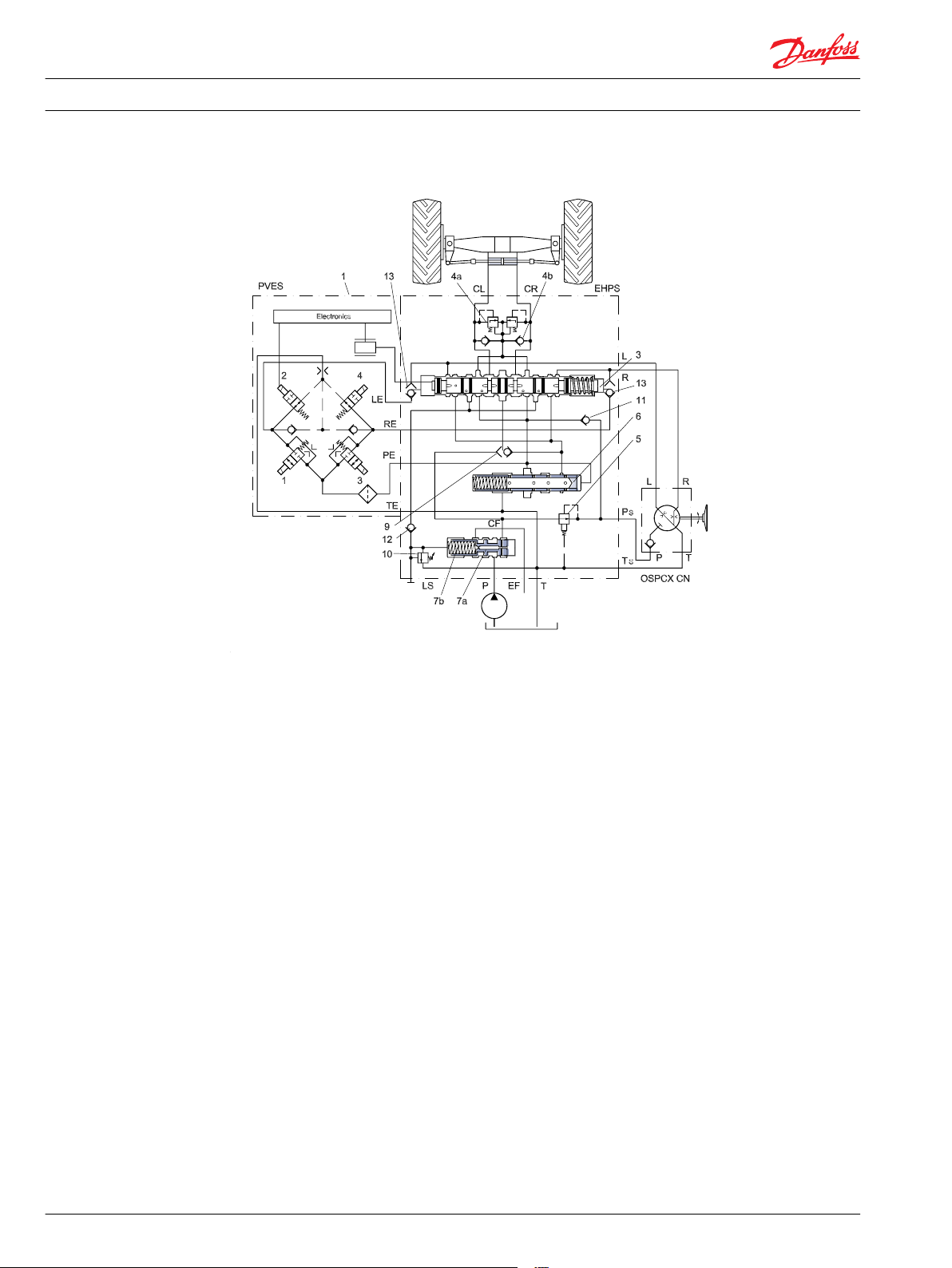
Neutral position
1. Electrical actuation module
3. Directional spool
4a. Shock valvea
4b. Suction valves
5. Pilot pressure reduction valve for steering unit
6. Metering valve
7a. Priority valve spool
7b. Priority valve spring
9. Emergency steering valve
10. Pilot pressure relief valve
11. Check valve for emergency steering
12. Check valve in LS line
13. Shuttle valves
When the engine is turned off, the priority valve spool (7a) is pushed to the right by the spring (7b).
The passage to the EF port is blocked and the passage to CF to the directional spool (3) is open.
When the engine is on and the steering unit OSPCX CN is in neutral position, the CF pressure will rise to
match the spring force in the integrated priority valve, and the spool (7a) will move to the left and the oil
will pass from the pump across the priority valve (7a + 7b) and out through the EF port.
14 520L0521 • Rev EB • May 2015
Page 15
P301 021
Technical Information EHPS Steering Valve PVE Actuation Module OSPCX CN Steering Unit
Steering valve EHPS and electrical actuation module PVE for EHPS
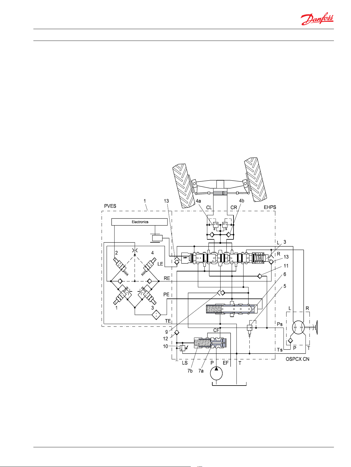
The priority valve is a “dynamic” type, meaning that a flow passes from CF through the Dynamic orifice
(integrated in spool 7a) and into the LS line through the check valve (12) to the directional spool (3). In
neutral position this dynamic oil flow passes on to the tank.
When the steering unit is in neutral position and no signal is generated to PVES, the directional spool will
be in its center position. This means that knocks and impacts from the cylinder are not transmitted to the
steering unit.
Steering left
When steering, the steering unit will get oil supplied from the pilot pressure reduction valve (5).
The pressure for the steering unit is reduced to approximate 30 bar.
When steering left, oil will be passing on to the L-port of the EHPS and it will fill the left side chamber of
the directional spool (3), which makes the spool move to the right.
1. Electrical actuation module
3. Directional spool
4a. Shock valvea
4b. Suction valves
520L0521 • Rev EB • May 2015 15
Page 16
Technical Information
EHPS Steering Valve PVE Actuation Module OSPCX CN Steering Unit
Steering valve EHPS and electrical actuation module PVE for EHPS
5. Pilot pressure reduction valve for steering unit
6. Metering valve
7a. Priority valve spool
7b. Priority valve spring
9. Emergency steering valve
10. Pilot pressure relief valve
11. Check valve for emergency steering
12. Check valve in LS line
13. Shuttle valves
When moving the directional spool (3), the LS signal will be connected to the steering pressure CL. The
pressure will then increase in the spring chamber of the priority valve and the priority valve spool (7a) will
be pushed towards the right side. Consequently, oil will flow through CF from the priority valve to the
directional spool (3).
Oil will now push the steering cylinder rod out and it will cause steering to the left side.
Return oil from the opposite cylinder site will stream into the CR port through the directional spool (3)
and into the right end of the metering valve (6). The metering valve spool is moved to the left and the
main stream from CR can pass through the metering valve into the tank.
The metering valve needs 12 bar to move. This return pressure is used for feeding an electrical actuation
module PVES in a EHPS type 1 system.
When the metering valve is open, it also leads pilot oil from the steering unit to the tank.
When the steering cylinder has reached end stop, no oil will pass through the CR port, and the control
pressure for the metering valve (6) will be reduced. The metering valve will now move to the right, and
the valve is closing the tank connection and the pilot oil flow will be blocked. This way you will feel the
end stop in the steering wheel.
When turning right, the movement of the directional spool (3) will be opposite. All other functions are
equal as when steering left. When steering with an electrical signal the directional spool (3) will be
controlled by hydraulic signal from the PVES which is converting electrical signal to hydraulic signal to
the directional spool (3), so that the movement of the directional spool (3) will be proportional to the
electrical signal to the PVES. The shuttle valves (13) will lead oil from PVES (1) to directional spool (3).
PVES and PVED-CLS, electrical actuation
The philosophy of Danfoss electrohydraulic actuation, type PVE, is integration of electronics, sensors and
actuators into a single unit that interfaces directly to the EHPS steering valve body.
16 520L0521 • Rev EB • May 2015
Page 17

Technical Information
EHPS Steering Valve PVE Actuation Module OSPCX CN Steering Unit
Steering valve EHPS and electrical actuation module PVE for EHPS
Closed loop control
All the proportional actuators feature an integrated feedback transducer that measures spool movement
in relation to the input signal, and by means of a solenoid valve bridge, controls the direction, velocity
and position of the directional spool of the valve. The integrated electronics compensate for flow forces
on the spool, internal leakage, changes in oil viscosity, pilot pressure, etc. This results in lower hysteresis
and better resolution. Furthermore the electronics enable built in safety like fault monitoring, directional
indication and LED light indication.
Principle
In principle the input signal (set-point signal) determines the level of pilot pressure which moves the
main spool. The position of the directional spool is sensed in the LVDT transducer which generates an
electric feed-back signal registered by the electronics. The variation between the set-point signal and
feed-back signal actuates the solenoid valves. The solenoid valves are actuated so that hydraulic pilot
pressure drives the directional spool into the correct position.
Inductive transducer, LVDT
(Linear Variable Differential Transformer). When the directional spool is moved, a voltage is induced
proportional to the spool position. The use of LVDT gives contact-free monitoring of the directional spool
position. This means an extra-long working life and no limitation as regards the type of hydraulic fluid
used. In addition, LVDT gives a precise position signal of high resolution.
Integrated pulse width modulation
Positioning of the directional spool in PVES is based on the pulse width modulation principle. As soon as
the directional spool reaches the required position, modulation stops and the spool is locked in position.
520L0521 • Rev EB • May 2015 17
Page 18

Technical Information EHPS Steering Valve PVE Actuation Module OSPCX CN Steering Unit
Technical data
EHPS
The technical data for EHPS are typical measured results. For the hydraulic system a mineral based
hydraulic oil with a viscosity of 21 mm2/s [102 SUS] and a temperature of 50°C [122°F] was used.
EHPS "stand alone"
Maximum pressure
Oil flow rated
Spool travel, directional
spool
Dead band, directional
spool
Priority valve
Oil temperature
Ambient temperature
Oil viscosity
Filtration
1)
At 6 mm [0.24 in] spool travel with directional spool for maximum cylinder and pilot flow (80/10)
2)
At 7 mm [0.28 in] spool travel (max travel) with directional spool for maximum cylinder and pilot flow (80/10)
Port P, EF, LS 250 bar [3625 psi]
Port CL/CR
Port L/R
Port Ps
Port T, Ts
Port P, EF 120 l/min [31.7 US gal/min]
Port CL/CR/T
Port L/R/Ps
Spring force 10 bar [145 psi]
Nominal flow
Recommended
temperature
Minimum temperature
Maximum temperature
Operating range
Minimum viscosity
Maximum viscosity
Maximum contamination
(ISO 4406, 1999 version)
320 bar [4641 psi]
125 bar [1812 psi]
55 bar [798 psi]
25 bar [363 psi]
80/96 l/min
10/12.5 l/min
± 7 mm [± 0.27 in]
± 1.5 mm [± 0.06 in]
120 l/min [31.7 US gal/min]
+30°C → +60°C [+86°F → +140°F]
-30°C [-22°F]
+90°C [+194°F]
-30°C → + 60°C [-22°F → +140°F]
12 - 80 mm2/s [65 - 370 SUS]
10 mm2/s [59 SUS]
460 mm2/s [2129 SUS]
21/19/16
1)2)
1)2)
[21/25 US gal/min]
[2.6/3.3 US gal/min]
Additional Data’s for EHPS with OLS 320
Priority valve, OLS 320
18 520L0521 • Rev EB • May 2015
Spring force 10 bar [145 psi]
Nominal flow
320 l/min [84.5 US gal/min]
Page 19

Technical Information EHPS Steering Valve PVE Actuation Module OSPCX CN Steering Unit
Technical data
PVES
PVES
Supply voltage U
DC
Current consumption at rated voltage PVES 0.57 A @ 12 V 0.3 A @ 24 V
Signal voltage neutral 0.5 x U
Signal current at rated voltage 0.25 mA to 0.70 mA
Input impedance in relation to 0.5 • U
DC
Input capacitor 100 ηF
Power consumption PVES 7 W
Reaction time
Supply voltage Function PVES
Disconnected by means of
neutral switch
Disconnected by means of
neutral switch
Constant voltage Reaction time from neutral position to max.
Constant voltage Reaction time from max. spool travel to neutral
Reaction time from neutral position to max.
spool travel
Reaction time from max. spool travel to neutral
position
spool travel
position
rated 11 V to 32 V
range 11 V to 32 V
max. ripple 5%
DC
CR-port ↔ CL-port 0.25 • UDC to 0.75 • U
12 KΩ
max. 0.230
rated 0.150
min. 0.120
max. 0.175
rated 0.090
min. 0.065
max. 0.200
rated 0.120
min. 0.050
max. 0.100
rated 0.090
min. 0.065
DC
Prop. super
s
PVED-CLS
Information is under preparation.
Hysteresis, PVES and PVED-CLS
1)
neutral.
520L0521 • Rev EB • May 2015 19
Hysteresis, PVES and PVED-CLS
1)
rated ∼ 0%
Hysteresis is indicated at rated voltage and f = 0.02 Hz for one cycle (one cycle = neutral ->full CL -> full CR ->
Page 20

157-669.11
Technical Information EHPS Steering Valve PVE Actuation Module OSPCX CN Steering Unit
Technical data
Spool travel
PVES and PVED-CLS
Oil consumption
Supply voltage Function PVES and PVED-CLS
Without voltage Pilot oil flow neutral 0.3 l/min [0.078 US gal/min]
With voltage Pilot oil flow locked 0.1 l/min [0.026 US gal/min]
continuous
actuations
0.8 l/min [0.211 US gal/min]
Oil viscosity
Oil viscosity range 12 - 75 mm2/s [65 - 347 SUS]
min. 4 mm2/s [39 SUS]
max. 460 mm2/s
[2128 SUS]
Note: Max. start up viscosity 2500 mm2/s
Oil temperature
Oil-temperature Rec. range 30 - 60˚C [86 -140˚F]
min. -30˚C [-22˚F]
max. 90˚C [194˚F]
Filtering
Filtering in the hydraulic system Max. allowed degree of contamination (ISO 4406, 1999 version):
23/19/16
Ambient temperature
Ambiant temperatur range Rec. -30° → +60°C [-22° → +140°F]
Pilot pressure
Pilot pressure (relative to T pressure) nom. 13.5 bar [196 psi]
min. 10 bar [145 psi]
max. 15 bar] [217 psi]
20 520L0521 • Rev EB • May 2015
Page 21

Technical Information EHPS Steering Valve PVE Actuation Module OSPCX CN Steering Unit
Technical data
Enclosure and connector version
AMP JPT connector Deutsch® connector
IP 66
IP 67
Installation PVED-CLS
Version of connector
Grade of enclosure
1)
According to the international standard IEC 529
1)
In particulary exposed applications, protection in the form of screening is recommended.
Information is under preparation.
520L0521 • Rev EB • May 2015 21
Page 22

Technical Information
EHPS Steering Valve PVE Actuation Module OSPCX CN Steering Unit
Variants
Variants of EHPS
In the table below is shown the available variants of the different modules in the EHPS valve.
EHPS valve module variants
Part Variants
Actuation module Type 0 (none) Type 1 (PVES) Type 2 (PVED-CLS)
Connection Connection
AMP DEUTSCH DEUTSCH 12 pin
Directional spool
Housing
Relieve valve,
bar [psi]
Shock valves,
bar [psi]
1)
Cylinder flow (CQ) l/min [US gal/min]
Pilot flow (PQ) (l/min) [US gal/min] 20 [5.28] 40 [10.57] 60 [15.85] 80 [21.13]
5 [1.32] CQ/PQ = 20/5 40/5 not available not available
8 [2.11] not available not available 60/8 80/8
10 [2.64] not available 40/10 60/10 CQ/PQ=80/10
2)
Thread
Basic G Metric UNF
Stand alone available available available
For PVG available available available
For OLS 320
100
[1450]
160
[2320]
3)
110
120
130
140
150
[1595]
[1740]
[1885]
[2030]
175
190 [2755] 210 [3045] 230 [3335] 240
[2175]
160
[2320]
[2538]
not available available available
170
180
190
200
210
[2465]
[2610]
[3480]
[2755]
250
[3626]
[2900]
265
[3843]
220
[3045]
[3190]
280 [4061] 300 [4351] 320
230
[3335]
240
[3480]
250
[3626]
[4641]
1) Directional spool:
Cylinder flow:
CQ = 20 l/min [5.28 US gal/min] is valid for 6 mm [0.24 in] spool travel.
CQ = 40 l/min [10.57 US gal/min] is valid for 6 mm [0.24 in] spool travel etc.
Pilot flow
PQ = 5 l/min [1.32 US gal/min] is based on steering unit with 50 cm3/rev and 100 min-1 [rpm] and causes
6 mm [0.24 in] spool travel at 100 min-1 [rpm] steering wheel speed
PQ = 8 l/min [2.11 US gal/min] is based on steering unit with 80 cm3/rev [4.88 in3/rev] and 100 min-1
[rpm] etc.
For example if you need 60 l/min [15.85 US gal/min] cylinder flow at 100 min-1 [rpm] steering wheel
speed and you need 80 cm3/rev [4.88 in3/rev] steering unit, you must choose directional spool 60/8.
2) Housing, threads:
P, EF Ps, Ts, T, CL, CR, L & R LS
G, DIN 3852-2 G 3/4 - S
Metric, ISO 6149-1 M 27 • 2 - O1) + S
2)
2)
UNF, ISO 11926-1 1 1/16 - 12 UN - O1) + S
1)
O-ring chamfer on port connection
2)
Spot face around port connection
2)
2)
G 1/2 - S
M 18 • 1.5 - O1) + S
2)
3/4 - 16 UNF - O1) + S
G 1/4 - S
M 12 • 1.5 - O1) + S
2)
7/16 - 20 UNF - O1) + S
2)
2)
2)
3) OLS320 for EHPS, Housing, threads:
22 520L0521 • Rev EB • May 2015
Page 23

Technical Information EHPS Steering Valve PVE Actuation Module OSPCX CN Steering Unit
Variants
P, EF LS
SAE-ports 1 in SAE flange/M10
threads
Metric, ISO 6149-1 M 33 • 2 - O1) + S
2)
UNF, ISO 11926-1 1 5/16 - 12 UN - O1) + S
3)
If LS connection is going from OLS320 to LS connection of EHPS
1)
O-ring chamfer on port connection
2)
Spot face around port connection
None3) or M 12 • 1.5 - O1) + S2) or 7/16 -20 UNF - O1) + S
M 12 • 1.5 - O1) + S
2)
7/16 - 20 UNF - O1) + S
2)
2)
2)
520L0521 • Rev EB • May 2015 23
Page 24

Technical Information
EHPS Steering Valve PVE Actuation Module OSPCX CN Steering Unit
Dimensioning
Dimensioning steering system with EHPS steering valve
The cylinder flow is determined from:
Steering cylinder volume.
•
Steering speed.
•
Dimension of steering cylinder(s) can be based on formulas in “General, steering components” page
29-31.
Symbols
V (l) steering cylinder volume
i (rev) number of steering wheel revolutions from lock to lock
Vvc (cm3/rev.) steering system displacement for steering cylinder
CQ (l/min) nominal cylinder flow
Pems (bar) emergency steering pressure
Tems (Nm) emergency steering torque
Fe (N) emergency steering wheel rim force
Swd (m) steering wheel diameter
Vvs (cm3/rev) displacement, steering unit
PQ (l/min) pilot flow
Qpm (l/min) pump flow, minimum
Example:
Cylinder volume: V = 1.85 l [0.49 US gal/min]
Required number of steering wheel revolutions from lock to lock:
i = 4 – 5 revolutions
The required steering system displacement for steering cylinder is calculated from
Vvc = V/i = (1.85*1000)/5 = 370 cm3/rev [22.6 in3]
(1.85*1000)/4 = 463 cm3/rev [28.3 in3]
In this example we chose Vvc = 400 cm3/rev
The directional spool is designated by nominal cylinder flow at 100 rpm speed on steering wheel.
CQ = 400 * 100/1000 (cm3/l) = 40 l/min [10.6 US gal/min]
The pilot flow is mainly determined by the demand for emergency steering pressure, look in “General ,
steering components” page 28-29.
Emergency steering pressure, Pems, is calculated to be maximum
Pems = 40 bar [580 psi]
Maximum allowable steering torque Tems based on steering wheel rim force Fe = 350 N and steering
wheel diameter Swd = 0.381 m [15 in]
Tems = Fe * Swd/2 = 350 * 0.381/2 = 66.7 Nm [590 lbf•in]
Pilot steering unit displacement can be chosen/calculated from the table lowest on page 28 in “General ,
steering components”.
The nearest displacement Vvs generating minimum 40 bar [580 psi] at Tws = 66.7 N•m [ 590 lbf•in]
Vvs maximum = 80 cm3/rev. [4.88 in3]
As in an EHPS steering system pilot oil is dumped to the tank the steering unit displacement should be as
small as possible.
In a given example you may be able to use a steering unit with smaller displacement as maximum size
acceptable for emergency steering pressure.
This is determined by the required speed for steering the vehicle in a situation without pump oil supply.
24 520L0521 • Rev EB • May 2015
Page 25

Technical Information EHPS Steering Valve PVE Actuation Module OSPCX CN Steering Unit
Dimensioning
In this example a 50 cm3 [3.01 in3] (Vvs chosen) steering unit could be big enough to obtain the required
steering speed in emergency steering mode.
Pilot flow PQ is chosen by:
PQ = Vvs chosen * 100 rpm = 50 cm3 [3.01 in3]/rev * 100 rpm = 5 l/min. [1.3 US gal/min]
Designation CQ/PQ for directional spool is: 40/5.
Calculating pump flow:
If cylinder movement must correspond to steering wheel speed up to 100 rpm, the minimum pump flow
Qpm for steering will be:
Qpm = CQ + PQ = 40 + 5 = 45 l/min [ 11.9 US gal/min]
If pump flow is insufficient, the steering cylinder speed will not match the steering wheel speed: the
faster you steer, the higher pilot flow will be, and less flow will be left for cylinder movement.
If you want to have sufficient supply at higher steering wheel speed (higher than 100 rpm) you must
choose enough pump capacity for such a case.
SeeDirectional spool - cylinder flow characteristic for all directional spools on page 27 for the different
directional spools. The “40 l/min [10,57 US gal/min]” spool gives maximum cylinder flow 50 l/min [13.21
US gal/min] at end stroke.
If you in the example above calculate with maximum steering wheel speed 150 rpm, the minimum pump
flow capacity must be:
Qpm = CQmax + PQmax = 50 + 7.5 = 58 l/min [15.32 US gal/min]
(Qmax comes from 50 cc/rev* 150 rpm = 7.5 l/min [1.98 US gal/min])
520L0521 • Rev EB • May 2015 25
Page 26

Technical Information
EHPS Steering Valve PVE Actuation Module OSPCX CN Steering Unit
Technical characteristics
Directional spool - oil flow characteristic for spool 40/5
A: Flow available for steering, CQa = QP-PQ
QP = Pump flow
PQ = Pilot flow
The lower left diagram shows pilot flow as function of steering wheel speed. The values are valid for
OSPCX 50 CN steering unit: 100 rpm steering wheel speed corresponds to 5 l/min. [1.3 US gal/min] pilot
flow.
The lower right diagram shows spool travel as function of pilot flow: 5 l/min. [1.3 US gal/min] pilot flow
gives 6 mm spool travel.
The upper right diagram shows cylinder flow as function of spool travel: 6 mm spool travel gives 40 l/min
[10.6 US gal/min] cylinder flow.
The upper left diagram shows cylinder flow as function of steering wheel speed: 100 rpm steering wheel
speed gives 40 l/min [10.6 US gal/min] cylinder flow.
Line A shows flow limit available for cylinder flow, when pump flow is 60 l/min. [15.9 US gal/min]. At 100
rpm 5 l/min. [1.3 US gal/min] is used for pilot flow.
Please contact the Danfoss Organization regarding characteristics for other directional spools.
26 520L0521 • Rev EB • May 2015
Page 27

1
l/min
a
2
4
5
6
Q
C
B
A
0.5 0.55 0.6 0.70 0.75
U
s
DC
U
mm
0.65
3
7
D
2
3
4
0.450.4
0.350.3
0.25
7 6
5
1
US gal/min
90
100
50
60
70
80
10
20
30
40
a
in
0.05 0.1 0.20.15 0.250.25 0.2 0.15 0.1 0.05
30
35
15
10
20
25
2.5
5
150H07.10
D
A
B
C
0
0
0 20
40
60
80
100
120
10
30
50
70
90
110
US gal/min
Q
30
150H15.11
p
0
5
10
15
20
25
p
Q
l/min
psi
P-T
1000
3500
200
75
0
100
175
bar
250
125
150
225
P-T
3000
2500
2000
1500
A
B
275
4000
Technical Information
EHPS Steering Valve PVE Actuation Module OSPCX CN Steering Unit
Technical characteristics
Directional spool - cylinder flow characteristic for all directional spools
A = valid for spools for nominal cylinder flow CQ = 20 l/min [5.3 US gal/min]
B = valid for spools for nominal cylinder flow CQ = 40 l/min [10.6 US gal/min]
C = valid for spools for nominal cylinder flow CQ = 60 l/min [15.9 US gal/min]
D = valid for spools for nominal cylinder flow CQ = 80 l/min [21.1 US gal/min]
Pilot pressure relief valve: (P - T, Qp) characteristic
The pilot pressure relief valve protects the steering system against excessive pressure. The pilot pressure
relief valve works together with the priority valve in the EHPS to limit the maximum steering pressure P-T.
The pilot pressure relief valve is set at an oil flow to the priority valve of 40 l/min [10.6 US gal/min].
Setting tolerance: rated value +5 bar [72.5 psi]
520L0521 • Rev EB • May 2015 27
Page 28

25
20
15
10
5
0
p
150H14.10
30
l/min
Q
US gal/min
110
90
70
50
30
10
120
100
80
60
40
200
400
28
450
300
200
250
100
50
0
150
350
P-EFP-EF
psi
16
12
32
bar
20
8
0
4
24
Q
p
10 bar
145 psi
min.
Technical Information
EHPS Steering Valve PVE Actuation Module OSPCX CN Steering Unit
Technical characteristics
A: 220 bar +5 / -0 bar [3190 + 72.5 / -0 psi]
B: 190 bar +5 / -0 bar [2756 + 72.5 / -0 psi]
Pressure drop P-EF for Danfoss EHPS valve
This data comes from measurements on a representative sample of EHPS valves from production. Oil with
viscosity of 21 mm2/s [102 SUS] at 50 °C [122 °F] was used during measuring. Measurement made when
pressure on the LS connection is zero. The minimum curve applies when the pressure on the EF
connection is higher than the actual control spring pressure. The curve for control spring pressure of 10
bar [145 psi] applies when pressure on the EF port is zero.
Pressure drop P-EF for OLS integrated in EHPS
Pressure drop P-EF for OLS 320 static priority valve flanged on EHPS
28 520L0521 • Rev EB • May 2015
Page 29

4.3[0.17]
109[4.29]
104[4.09]
30[1.18]
68[2.68]44.5[1.752]37[1.46]
44.5[175]
229[9.02]
4[0.16]
51[2.01]
23.5[0.925]
73[2.87]
37[1.47]42[1.65]33[1.30]
42[1.65]
150H18.12
RCRCLL
122[[4.80]
EHPS
XXXXXXXX
XXXXXXXX
MADE IN DENMARK
T
EF
LS
TS
P
PS
150H19.11
78[3.07]
47.5[1.870] 47.5[1.870]
83.5[3.287]
22.5[0.886]
B
68[2.68]
14[0.55]
47.5[1.870]47.5[1.870]
4.3[0.17]
83.5[3.287]
A
Technical Information EHPS Steering Valve PVE Actuation Module OSPCX CN Steering Unit
Dimensions
EHPS type 0, stand alone
520L0521 • Rev EB • May 2015 29
Page 30

Technical Information EHPS Steering Valve PVE Actuation Module OSPCX CN Steering Unit
Dimensions
P, EF Ps, Ts, T, CL, CR, L, R LS
G-port version (G, DIN
3852-2)
Metric-port version (ISO
6149-1)
UNF-port version (ISO
11926-1)
All versions: M8 • 1.25, 10 mm [0.39 in] deep M8 • 1.25, 10 mm [0.39 in] deep
The mounting surface for the EHPS must be plane. No spots exceeding the height of the area round the
three M8 bolt holes allowed.
G 3/4, 16 mm [0.63 in] deep G 1/2, 14 mm [0.55 in] deep G 1/4, 12 mm [0.48 in] deep
M27 • 2, 19 mm [0.75 in]
deep
1 1/16 -12 UN, 19 mm [0.75
in] deep
A B
M18 • 1.5, 14.5 mm [0.57 in]
deep
3/4 -16 UNF 14 mm [0.55 in]
deep
M12 • 1.5, 11.5 mm [0.45460
mm²/s in] deep
7/16 -20 UNF, 11.5 mm
[0.45 in] deep
30 520L0521 • Rev EB • May 2015
Page 31

4.3[0.17]
109[4.29]
104[4.09]
30[1.18]
68[2.68]44.5[1.752]37[1.46]
44.5[175]
317[12.48]
4[0.16]
51[2.01]
23.5[0.925]
73[2.87]
37[1.47]42[1.65]33[1.30]
127[4.96]
42[1.65]
150H09.12
RCRCLL
EHPS
XXXXXXXX
XXXXXXXX
MADE IN DENMARK
T
EF
LS
TS
P
PS
150H11.11
78[3.07]
47.5[1.870] 47.5[1.870]
83.5[3.287]
22.5[0.886]
B
68[2.68]
14[0.55]
47.5[1.870]47.5[1.870]
4.3[0.17]
83.5[3.287]
A
Technical Information EHPS Steering Valve PVE Actuation Module OSPCX CN Steering Unit
Dimensions
EHPS type 1, stand alone
520L0521 • Rev EB • May 2015 31
Page 32

Technical Information EHPS Steering Valve PVE Actuation Module OSPCX CN Steering Unit
Dimensions
P, EF Ps, Ts, T, CL, CR, L, R LS
G-port version (G, DIN
3852-2):
Metric-port version (ISO
6149-1)
UNF-port version (ISO
11926-1)
All versions: M8 • 1.25, 10 mm [0.39 in] deep M8 • 1.25, 10 mm [0.39 in] deep
The mounting surface for the EHPS must be plane. No spots exceeding the height of the area round the
three M8 bolt holes allowed.
G 3/4, 16 mm [0.63 in] deep G 1/2, 14 mm [0.55 in] deep G 1/4, 12 mm [0.48 in] deep
M27 • 2, 19 mm [0.75 in]
deep
1 1/16 -12 UN, 19 mm [0.75
in] deep
A B
M18 • 1.5, 14.5 mm [0.57 in]
deep
3/4 -16 UNF 14 mm [0.55 in]
deep
M12 • 1.5, 11.5 mm [0.45 in]
deep
7/16 -20 UNF, 11.5 mm
[0.45 in] deep
32 520L0521 • Rev EB • May 2015
Page 33

150H12.13
104[4.09]
P T
A
B
4.3[0.17]
317[12.48]
44.5[175]
37[1.46] 44.5[1.752] 68[2.68]
L
24[0.94]
8[0.31]
86[3.39]
24[0.94]
33[1.30]
127[5.00]
51[2.01]
35[1.38]42[1.65]
75[2.95]
23.5[0.925]
L CL CR R
42[1.65] 109[4.29]
4[0.16]
35[1.38]
LS
EHPS+PVG
XXXXXXXX
XXXXXXXX
MADE IN DENMARK
T
EF
LS
TS
P
PS
max.292[11.5]
115.5[4.547]
112.5[4.429]
150H13.11
127[5.00]
LS
40[1.57]
Technical Information EHPS Steering Valve PVE Actuation Module OSPCX CN Steering Unit
Dimensions
EHPS type 1, with PVG
520L0521 • Rev EB • May 2015 33
Page 34

Technical Information EHPS Steering Valve PVE Actuation Module OSPCX CN Steering Unit
Dimensions
P, EF Ps, Ts, T, CL, CR, L, R LS
G-port version (G, DIN
3852-2)
Metric-port version (ISO
6149-1)
UNF-port version (ISO
11926-1)
All versions Bottom side fixing holes (A) in EHPS block, see page 29; M8 x 1.25, 10 mm
PVB 1 2 3 4 5 6 7 8
L1 mm
[in]
208
[8.19]
G 3/4, 16 mm [0.63 in] deep G 1/2, 14 mm [0.55 in] deep G 1/4, 12 mm [0.48 in] deep
M27 • 2, 19 mm [0.75 in]
deep
1 1/16 -12 UN, 19 mm [0.75
in] deep
A
[0.39 in] deep
256
[10.08]
304
[12.00]
M18 • 1.5, 14.5 mm [0.57 in]
deep
3/4 -16 UNF 14 mm [0.55 in]
deep
352
[13.86]
400
[15.75]
448
[17.64]
M12 • 1.5, 11.5 mm [0.45 in]
deep
7/16 -20 UNF, 11.5 mm
[0.45 in] deep
496
[19.53]
544
[21.42]
34 520L0521 • Rev EB • May 2015
Page 35

RCRCLL
113[4.45]
X
80[3.15] 47[1.85]
150H24.13
54[2.13]
37[1.46]
126[4.96] 68[2.68]
42[1.65] 36[1.42]
73[2.87]
23.5[0.925]
78.5[3.091]
163[6.42]
31[1.22] 38[1.50]
47.5[1.870]
95[3.74]
85[3.35]
4.3[0.169]
317[12.48]
40[1.57]
236[9.29]
68[2.68]
A
55[2.17]
X
EF
P
EHPS+CLS 320
XXXXXXXX
XXXXXXXX
MADE IN DENMARK
47.5[1.870]
30[1.181]
118[4.646]
74[2.91)
4[0.16]
23.5[0.925]
56[2.20]
T
EF
LS
TS
P
PS
LS
Technical Information EHPS Steering Valve PVE Actuation Module OSPCX CN Steering Unit
Dimensions
EHPS type 1, with OLS 320
520L0521 • Rev EB • May 2015 35
Page 36

Technical Information EHPS Steering Valve PVE Actuation Module OSPCX CN Steering Unit
Dimensions
EHPS
P, EF Ps, Ts, T, CL, CR, L, R LS
G-port version (G, DIN
3852-2):
Metric-port version (ISO
6149-1)
UNF-port version (ISO
11926-1)
OLS 320
SAE-port version
Metric-port version (ISO
6149-1)
UNF-port version: (ISO
11926-1)
G 3/4, 16 mm [0.63 in] deep G 1/2, 14 mm [0.55 in] deep G 1/4, 12 mm [0.48 in] deep
M27 • 2, 19 mm [0.75 in]
deep
1 1/16 -12 UN, 19 mm [0.75
in] deep
P, EF LS
1 in SAE flange/M10
threads
M33 • 2, x = ø43 mm (in) M12 • 1.5, 11.5 mm deep
1 5/16 -12 UN, x = ø49mm
( in)
M18 • 1.5, 14.5 mm [0.57 in]
deep
3/4 -16 UNF 14 mm [0.55 in]
deep
G 1/4, 12 mm deep
LS: M12 • 1.5, 11.5 mm deep
LS: 7/16 - 20 UNF, 11.5 mm deep
7/16 -20 UNF, 11.5 mm deep
M12 • 1.5, 11.5 mm [0.45 in]
deep
7/16 -20 UNF, 11.5 mm
[0.45 in] deep
A:
All versions Bottom side fixing holes: M8 x 1.25, 10 mm deep, see
page 29.
36 520L0521 • Rev EB • May 2015
Page 37

T
P
150H06.11
OSPCX CN
L
P
T
R
EHPS
CL
R
CR
L
Ps
Ts
type 0
EF LS
T
P
150H05.11
OSPCX CN
L
P
T
R
PVRES
EHPS
CL
R
CR
L
Ps
Ts
type 1
EF LS
Electronics
1
2
TE
3
PE
RE
LE
4
PVES
Technical Information
EHPS Steering Valve PVE Actuation Module OSPCX CN Steering Unit
Hydraulic systems
EHPS type 0, stand alone and OSPCX CN steering unit
EHPS type 1, stand alone, OSPCX CN steering unit and PVRES joystick
The vehicle can be steered with either the PVRES joystick or the OSPCX CN steering unit. The signal from
the steering unit has priority on simultaneous activation of steering wheel and joystick.
520L0521 • Rev EB • May 2015 37
Page 38

T
P
150-575.14
T
OSPCX CN
L
P
T
R
PVG 32
M
B
EHPS
CL
R
CR
L
Ps
Ts
type 1
A
A
B
A
B
PVRES
Electronics
PVES
T
LS
1
2
3
4
TE
PE
RE
LE
P
Technical Information
EHPS Steering Valve PVE Actuation Module OSPCX CN Steering Unit
Hydraulic systems
EHPS type 1 with PVG 32, OSPCX CN pilot steering unit and PVRES joystick
The vehicle can be steered with either the PVRES joystick or the OSPCX CN steering unit. The signal from
the steering unit has priority on simultaneous activation of steering wheel and joystick.
The joystick must be equipped with a neutral position contact to ensure that the PVES is not under
tension in neutral position. PVRES joystick has a neutral position contact.
See Technical information for joysticks 520L0554
38 520L0521 • Rev EB • May 2015
Page 39

P301 023
Technical Information
System safety
Emergency steering
EHPS Steering Valve PVE Actuation Module OSPCX CN Steering Unit
1. Electrical actuation module
3. Directional spool
4a. Shock valves
4b. Suction valves
5. Pilot pressure reduction valve for steering unit
6. Metering valve
7a. Priority valve spool
7b. Priority valve spring
9. Emergency steering valve
10. Pilot pressure relief valve
11. Check valve for emergency steering
12. Check valve in LS line
13. Shuttle valves
When the pump oil supply fails*, the steering unit can be used as a hand pump depending on the weight
of vehicle.
520L0521 • Rev EB • May 2015 39
Page 40

Technical Information
EHPS Steering Valve PVE Actuation Module OSPCX CN Steering Unit
System safety
When steering the steering unit still gets oil from Ps on EHPS. When steering left the oil from the steering
unit passes on to the L-port of the EHPS and it will fill the left side chamber of the directional spool (3),
and so the spool moves to the right.
As there is no pump supply, there is no pressure in CF consequently there is no pressure on the left side
of the emergency steering valve (9). Pilot oil from the steering unit is pushing on the right side of
emergency steering valve, and causing it to move towards the left. Now pilot flow is led to the directional
spool (3) and into the CL port and the cylinder moves. Return oil from the cylinder enters CR, and will pass
over the directional spool (3) and the check valve (11) and it feeds the steering unit.
In this way the cylinder is directly moved by the oil flow from the steering unit, and the ratio is increased
in comparison to normal steering situation with active pump supply.
When turning right, the movement of the directional spool (3) will be opposite. All other functions are
equal as when steering left.
* Herby is meant when pressure in P-line to EHPS has dropped to less than 12 bar [174 psi]!! When pump
pressure is larger than 12 bar [174 psi], emergency steering will not be possible due to metering valve (6)
will stay open during steering.
EHPS type 1 and type 2, prioritizing input signal
In case of active electrical steering (EHPS type 1 and type 2), the steering signal from pilot steering unit
has highest priority:
The oil supply to the steering unit is reduced to 30 bar [435 psi], controlled by pressure reduction
•
valve (5)
The oil supply to the PVES actuation module is adjusted to 12 bar [174 psi] by the metering valve (6)
•
If a driver coincidence activates a joystick steering left, and he grabs the steering wheel to steer counter
(steer to the right), the signal from the steering wheel has priority as the pilot steering unit can generate
30 bar [435 psi] on the right side of the directional spool and the PVES can only generate 12 bar [174 psi]
on the left side of the directional spool.
The joystick must be equipped wit a neutral contact to ensure that the PVES is not under tension in
neutral position. Without a neutral position contact the joystick will release an electrical signal of 0.5 •
UDC.
If the EHPS is hydraulically activated the main spool is moved, thus changing the LVDT signal. There will
be a difference between feedback and input signal and when this reaches more than 15% the PVEA will
go into failure mode.
Note concerning type 1 and type 2 systems.
Such systems can be set up without any OSPCX steering unit in case the customer wants pure Steer By
Wire (SBW) steering.
In such case it is important to connect L and R of EHPS to tank.
These tank connections are needed to ensure that directional spool of EHPS moves properly into neutral
after ending steering input signal to PVE!
Fault monitoring
A fault monitoring system is provided in all PVES and PVED-CL modules. The system is available as passive
fault monitoring type, which provides a warning signal only.
Passive fault monitoring systems are triggered by three main events:
•
40 520L0521 • Rev EB • May 2015
Page 41

W
Technical Information
System safety
EHPS Steering Valve PVE Actuation Module OSPCX CN Steering Unit
1. Input signal monitoring
The PVES input signal voltage is continuously monitored. The permissible range is between 15%
and 85% of the supply voltage. Outside this range the section will switch into an active error state.
2. Transducer supervision
If one of the wires to the LVDT sensor is broken or short-circuited, the section will switch into an
active error state.
3. Supervision of the closed loop
The actual position must always correspond to the demanded position (input signal). If the actual
spool position is further than the demanded spool position (>12%, ), the system detects an error
and will switch into an active error state. On the other hand, a situation where the actual position is
closer to neutral than that demanded will not cause an error state. This situation is considered “in
control”.
When an active error state occurs, the fault monitoring logic will be triggered:
Passive fault monitoring
A delay of 250 ms before anything happens.
•
The solenoid valve bridge will not be disabled but still control the main spool position.
•
An alarm signal is sent out through the appropriate pin connection, no. 3.
•
This state is not memorized. When the erroneous state disappears, the alarm signal will turn to
•
passive again. However, the signal will always be active for a minimum of 100 ms when triggered.
To prevent the electronics from going into an undefined state, a general supervision of the power supply
and the internal clock frequency is made. This function applies to PVES and will not activate fault
monitoring:
1. High supply voltage:
The solenoid valves are disabled when the supply voltage exceeds 36 V, and the main spool will
return/stay in neutral.
2. Low supply voltage:
The solenoid valves are disabled when the supply voltage falls below 8.5 V, and the main spool will
return/stay in neutral.
3. Internal clock.
The solenoid valves are disabled when the internal clock frequency fails, and the main spool will
return/stay in neutral.
Safety considerations
Warning
The Danfoss range of PVE actuators are single string designs with limited on board fault monitoring.
Danfoss strongly recommends application of vehicle specific safety monitoring systems that will detect
non-conforming steering and effectively disable electro-hydraulic actuators or issue appropriate
warnings as the case may be. A minimum safety system should include a manual power switch to
electrical power off electrohydraulic actuators while driving on public roads.
520L0521 • Rev EB • May 2015 41
Page 42

W
Technical Information EHPS Steering Valve PVE Actuation Module OSPCX CN Steering Unit
System safety
Safety considerations
On-road operation
Warning
The PVES or PVED-CLS shall be de-energized while driving on-road. It is the OEMs responsibility to
establish the necessary means to inform and de-energize the PVE from the cabin when driving on public
roads.
The Danfoss range of PVE actuators are single string designs with limited on board fault monitoring.
Danfoss strongly recommends application of vehicle specific safety monitoring systems that will detect
non-conforming steering and effectively disable electro-hydraulic actuators or issue appropriate
warnings as the case may be. A minimum safety system should include a manual power switch to
electrical power off electro-hydraulic actuators while driving on public roads.
For details, see:
•
Technical information, PVE Series 4
•
User Manual PVED-CL controller for Electro-Hydraulics Steering
or contact Danfoss Technical Support Team
42 520L0521 • Rev EB • May 2015
Page 43

EHPS Type 1A 80/8 OLS M M 240 320 PB
Actuation module
Directional spool
Housing, basic
Housing EHPS, threads
Housing OLS 320
(if any OLS), threads
Relief valve setting, EHPS
Shock valves setting
Unit painted black
Please fill in specification
for your EHPS:
EHPS
Technical Information
EHPS Steering Valve PVE Actuation Module OSPCX CN Steering Unit
Order specification
Order specification for EHPS and PVE
Specification table for Danfoss EHPS steering valve. Fill in your company data and place x’s in the table
where appropriate and then send to your Danfoss Power Solutions, sales organization. For further
explanation of specification: see page 22
Your company Name Vehicle Potential pcs/year Completed by Date
Actuation module Type 0 (none) Type 1 (PVES) Type 21) (PVED-CLS)
Connector Connector
AMP (A) DEUTSCH DEUTSCH
Directional spool 20/5 40/5 40/10 60/8 60/10 80/8 80/10
Housing, basic Stand alone (SA) For PVG (PVG) For OLS 320(OLS)
Housing EHPS, threads G Metric (M) UNF
1)
Housing OLS 320, threads
SAE Metric (M) UNF
(if any OLS 320)
Relief valves setting
100 110 120 130 140 150 160 170 180 190 200 210 220 240 250
bar
Shock valves setting
160 175 190 210 230 240 250 265 280 300 320
bar
Unit painted black Yes (PB) No
Contact Danfoss Sales Organization for software version and vehicle specific parameters to be downloaded in PVED-CLS
Only values stated in the table above are available for the EHPS specification.
When choosing housing for PVG, please fill in order specification for the PVG group.
In this PVG group the EHPS will replace the end cover for PVG.
Remember also to specify and order the OSPCX CN steering unit, Specification table for non catalogue
numbers of Danfoss OSPCX CN steering units on page 46.
520L0521 • Rev EB • May 2015 43
Page 44

Technical Information
Steering unit OSPCX CN
Version
EHPS Steering Valve PVE Actuation Module OSPCX CN Steering Unit
Closed center
Closed center steering units are blocked on their P port in the neutral position.
OSPCX CN: Steering units for steering valve EHPS.
OSPCX CN is a closed center steering unit with the L and the R connections open to the tank when in
neutral position. OSPCX CN can only be used with Danfoss steering valve EHPS.
OSPCX CN steering unit must not be connected directly to the steering cylinder.
OSPBCX CN Closed center Non-reaction
44 520L0521 • Rev EB • May 2015
Page 45

Technical Information EHPS Steering Valve PVE Actuation Module OSPCX CN Steering Unit
Code numbers and weights
OSPCX closed center non-reaction steering units
OSPCX CN in the table below have all the following valve function incorporated:
Check valve in P-port
•
OSPCX CN in the table below have all soft neutral setting springs, see page 42
Steering unit Code numbers Weight
Connections kg
European versions Us Versions
**
G 1/2 S
OSPCX 50 CN - - 11031535 5.2
OSPCX 70 CN 150G4110 - - 5.3
OSPCX 80 CN - - 150G4112 5.3
OSPCX 100 CN 150G4107 150G4108 150G4109 5.4
**
countersinking around port connections (cannot be used in connection with OVR angular block)
*
O-ring chamfer on port connections
M18 • 1.5 - O* + S
If you wish other specifications for your OSPCX CN steering unit, please fill in the order form on page 39
and contact the Danfoss sales organization.
**
3/4 - 16 UNF O
*
[lb]
[11.5]
[11.7]
[11.7]
[11.9]
520L0521 • Rev EB • May 2015 45
Page 46

Technical Information EHPS Steering Valve PVE Actuation Module OSPCX CN Steering Unit
Order specification
Specification table for non catalogue numbers of Danfoss OSPCX CN steering units
Specification table for Danfoss closed center steering units type OSPCX CN which are not available in the
code number table.
Fill in with company data and x’s in the table and send to your Danfoss Sales Organization
Your company Name Vehicle Potential, pcs/year Completed Date
Steering unit type OSPCX CN
Displacement cm3/rev
OSPCX CN
Port threads
50 60 70 80 100
G 1/2 S
**
M 18 • 1.5 O* + S
**
3/4-16 UNF O
*
Neutral setting springs Soft: 0.15-1.8 N•m [1.33-15.9 lbf•in]
in normal steering situation
Standard: 0.8-3 N•m [7.10-26.55 lbf•in] in normal
steering situation
Unit painted black Yes No
**
Spot face around port connections (can not be used in connection with OVR angular block)
*
O-ring chamfer on port connections
Strong: 1.5-4 N•m [13.27-35.40 lbf•in]
in normal steering situation
46 520L0521 • Rev EB • May 2015
Page 47

Technical Information EHPS Steering Valve PVE Actuation Module OSPCX CN Steering Unit
Technical data
Common data
Look in sub catalogue: “General, steering components“
Manual steering pressure
Look in sub catalogue: “General, steering components “
Displacement, flow and pressure
OSPCX
Steering unit Displacement Ratet oil flow Max. pressure on connections
cm3/rev [in3/rev] l/min [US gal/
min]
OSPCX 50 CN 50 [3.05] 5 [1.32] 125 [1813] 25 [363] 100 [1450]
OSPCX 60 CN 60 [3.70] 6 [1.58]
OSPCX 70 CN 70 [4.30] 7 [1.85]
OSPCX 80 CN 80 [4.90] 8 [2.11]
OSPCX 100 CN 100 [6.10] 10 [2.64]
P T L, R
bar [psi] bar [psi] bar [psi]
520L0521 • Rev EB • May 2015 47
Page 48

Technical Information EHPS Steering Valve PVE Actuation Module OSPCX CN Steering Unit
Dimensions
Dimensions OSPCX CN
A: B:
European version: G 1/2 with spot face or M18 • 1.5 ISO 6149
15 mm [0.59 in] deep
US version: 3/4 - 16 UNF O-ring boss;
15 mm [0.59 in] deep
Steering unit L
OSPCX 50 CN 126
OSPCX 60 CN 128
OSPCX 70 CN 128
OSPCX 80 CN 129
OSPCX 100 CN 132
1
mm [in] mm [in]
[4.96]
[5.04]
[5.04]
[5.08]
[5.20]
M10 • 1.5,
16 mm [0.63 in] deep
3/8 - 16 UNC,
16 mm [0.63 in] deep
L
2
6.5
9.1
9.1
10.4
13.0
[0.26]
[0.36]
[0.36]
[0.41]
[0.51]
48 520L0521 • Rev EB • May 2015
Page 49

Technical Information EHPS Steering Valve PVE Actuation Module OSPCX CN Steering Unit
520L0521 • Rev EB • May 2015 49
Page 50

Technical Information EHPS Steering Valve PVE Actuation Module OSPCX CN Steering Unit
50 520L0521 • Rev EB • May 2015
Page 51

Technical Information EHPS Steering Valve PVE Actuation Module OSPCX CN Steering Unit
520L0521 • Rev EB • May 2015 51
Page 52

Danfoss
Power Solutions GmbH & Co. OHG
Krokamp 35
D-24539 Neumünster, Germany
Phone: +49 4321 871 0
Danfoss
Power Solutions ApS
Nordborgvej 81
DK-6430 Nordborg, Denmark
Phone: +45 7488 2222
Danfoss
Power Solutions (US) Company
2800 East 13th Street
Ames, IA 50010, USA
Phone: +1 515 239 6000
Danfoss
Power Solutions Trading
(Shanghai) Co., Ltd.
Building #22, No. 1000 Jin Hai Rd
Jin Qiao, Pudong New District
Shanghai, China 201206
Phone: +86 21 3418 5200
Products we offer:
Comatrol
www.comatrol.com
Schwarzmüller-Inverter
www.schwarzmuellerinverter.com
Turolla
www.turollaocg.com
Hydro-Gear
www.hydro-gear.com
Daikin-Sauer-Danfoss
www.daikin-sauer-danfoss.com
Bent Axis Motors
•
Closed Circuit Axial Piston
•
Pumps and Motors
Displays
•
Electrohydraulic Power
•
Steering
Electrohydraulics
•
Hydraulic Power Steering
•
Integrated Systems
•
Joysticks and Control
•
Handles
Microcontrollers and
•
Software
Open Circuit Axial Piston
•
Pumps
Orbital Motors
•
PLUS+1® GUIDE
•
Proportional Valves
•
Sensors
•
Steering
•
Transit Mixer Drives
•
Danfoss Power Solutions is a global manufacturer and supplier of high-quality hydraulic and
electronic components. We specialize in providing state-of-the-art technology and solutions
that excel in the harsh operating conditions of the mobile off-highway market. Building on
our extensive applications expertise, we work closely with our customers to ensure
exceptional performance for a broad range of off-highway vehicles.
We help OEMs around the world speed up system development, reduce costs and bring
vehicles to market faster.
Danfoss – Your Strongest Partner in Mobile Hydraulics.
Go to www.powersolutions.danfoss.com for further product information.
Wherever off-highway vehicles are at work, so is Danfoss. We offer expert worldwide support
for our customers, ensuring the best possible solutions for outstanding performance. And
with an extensive network of Global Service Partners, we also provide comprehensive global
service for all of our components.
Please contact the Danfoss Power Solution representative nearest you.
Danfoss can accept no responsibility for possible errors in catalogues, brochures and other printed material. Danfoss reserves the right to alter its products without notice. This also applies to
products already on order provided that such alterations can be made without changes being necessary in specifications already agreed.
All trademarks in this material are property of the respective companies. Danfoss and the Danfoss logotype are trademarks of Danfoss A/S. All rights reserved.
520L0521 • Rev EB • May 2015 www.danfoss.com
Local address:
©
Danfoss A/S, 2015
 Loading...