

Page 1
Service Manual
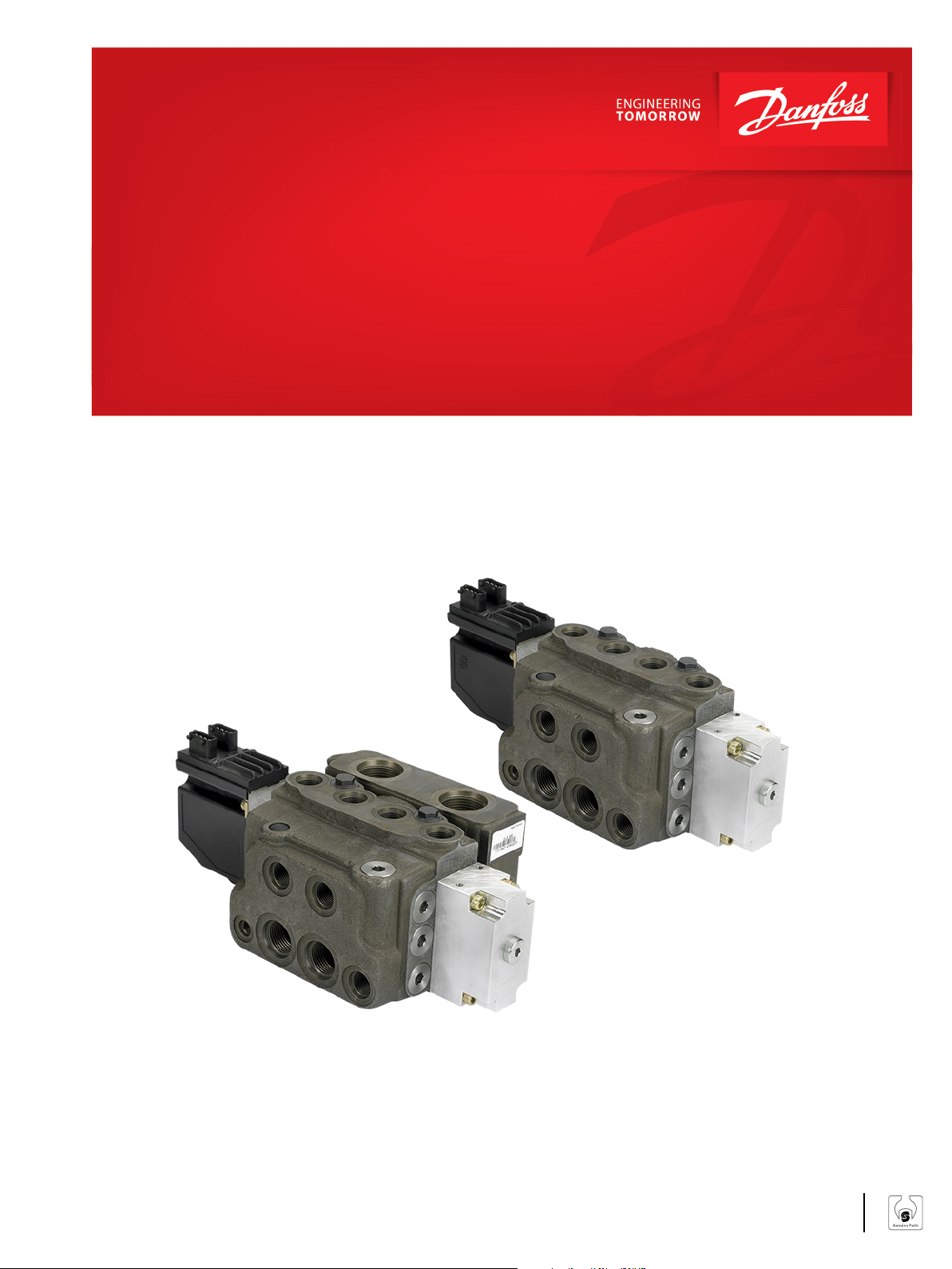
Steering Valve
EHPS and EHPS with OLS 320
powersolutions.danfoss.com
Page 2

Service Manual
EHPS Steering Valve and OLS 320
Revision history Table of revisions
Date Changed Rev
July 2016 Updated EHPS spare parts list 0102
June 2015 First version AA
2 | © Danfoss | July 2016 AX00000235en-US0102
Page 3

Service Manual
EHPS Steering Valve and OLS 320
Contents
Safety Precautions
Safety precautions............................................................................................................................................................................4
Service Literature
Symbols Used in Danfoss Literature..........................................................................................................................................5
EHPS versions.....................................................................................................................................................................................5
Exploded view
EHPS type 0, 1 and 2 exploded view......................................................................................................................................... 6
EHPS spare parts list........................................................................................................................................................................ 7
EHPS with flanged on OLS 320 exploded view......................................................................................................................9
EHPS and OLS 320 spare parts list............................................................................................................................................10
Seal kits and spare parts for EHPS and OLS 320..................................................................................................................11
Tools
Tools for EHPS................................................................................................................................................................................. 12
Disassembly and assembly
Disassembly of EHPS.....................................................................................................................................................................13
Assembly of EHPS.......................................................................................................................................................................... 23
Disassembly of OLS 320 and priority valve spool of EHPS..............................................................................................31
Assembly of OLS 320 and priority valve spool of EHPS....................................................................................................35
Testing
Testing of EHPS...............................................................................................................................................................................39
Set up for testing the EHPS................................................................................................................................................... 39
Steering test using pilot steering unit type OSPCX CN...............................................................................................39
Pilot relief valve for EHPS.......................................................................................................................................................40
Neutral positioning test, OSP part for EHPS....................................................................................................................40
Steering and neutral positioning test, EH part with EHPS.........................................................................................40
Manual steering with EHPS...................................................................................................................................................40
Testing of EHPS with OLS 320................................................................................................................................................... 41
Set up for testing the EHPS with OLS 320........................................................................................................................41
©
Danfoss | July 2016 AX00000235en-US0102 | 3
Page 4

W
W
W
W
W
Service Manual
EHPS Steering Valve and OLS 320
Safety Precautions
Safety precautions
Always consider safety precautions before beginning a service procedure. Protect yourself and others
from injury. Take the following general precautions whenever servicing a hydraulic system.
Warning
Unintended Machine Movement
Unintended movement of the machine or mechanism may cause injury to the technician or bystanders.
To prevent unintended movement, secure the machine or disable / disconnect the mechanism while
servicing.
Warning
Flammable Cleaning Solvents
Some cleaning solvents are flammable. To eliminate the risk of fire, do not use cleaning solvents in an
area where a source of ignition may be present.
Warning
Fluid under Pressure
Escaping hydraulic fluid under pressure can have sufficient force to penetrate your skin causing serious
injury and/or infection. This fluid may also be hot enough to cause burns. Use caution when dealing with
hydraulic fluid under pressure. Relieve pressure in the system before removing hoses, fittings, gauges, or
components. Never use your hand or any other body part to check for leaks in a pressurized line. Seek
medical attention immediately if you are cut by hydraulic fluid.
Warning
Personal Safety
Protect yourself from injury. Use proper safety equipment, including safety glasses, at all times.
Warning
Product Safety
Steering valves are safety components and therefore it is extremely important that the greatest care is
taken when servicing these products. There is not much wear on a steering valve and therefore they
normally outlast the application they are built into. Therefore the only recommended service work on
steering valves is:
•
Changing seals and o-rings
•
Disassemble, clean, and assemble if contaminated
•
Hydraulic testing, including valve setting
4 | © Danfoss | July 2016 AX00000235en-US0102
Page 5
Service Manual
EHPS Steering Valve and OLS 320
Service Literature
Symbols Used in Danfoss Literature
•
= Non removable part, use a new part
•
= External hex head
•
= Internal hex head
•
= Lubricate with hydraulic fluid
•
= Inspect for wear or damage
•
= Note correct orientation
•
= Mark orientation for reinstallation
•
= Torque specification
•
= Press in - press fit
•
= Pull out with tool - press fit
EHPS versions
This service literature is valid for:
•
EHPS type 0: EHPS without PVE actuation module
•
EHPS type 1 and 2: EHPS with PVE actuation module
•
EHPS with flanged on priority valve module, OLS 320
©
Danfoss | July 2016 AX00000235en-US0102 | 5
Page 6
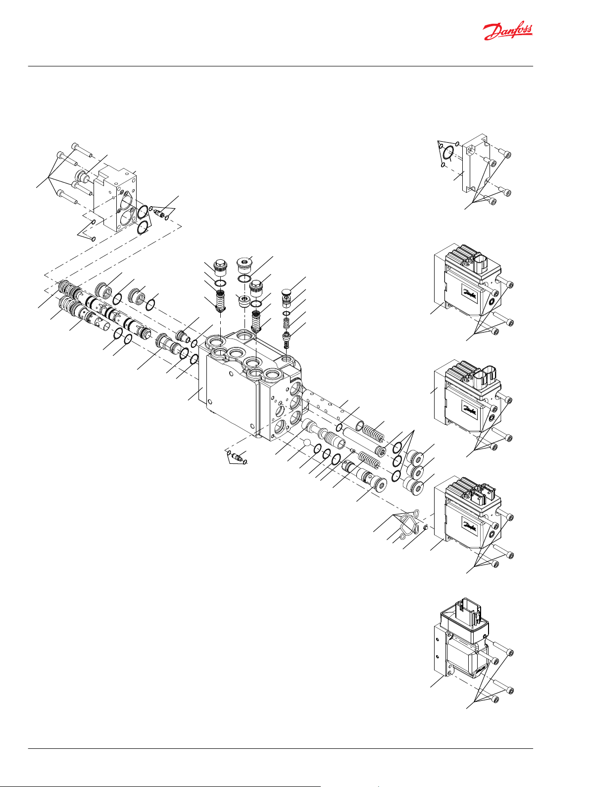
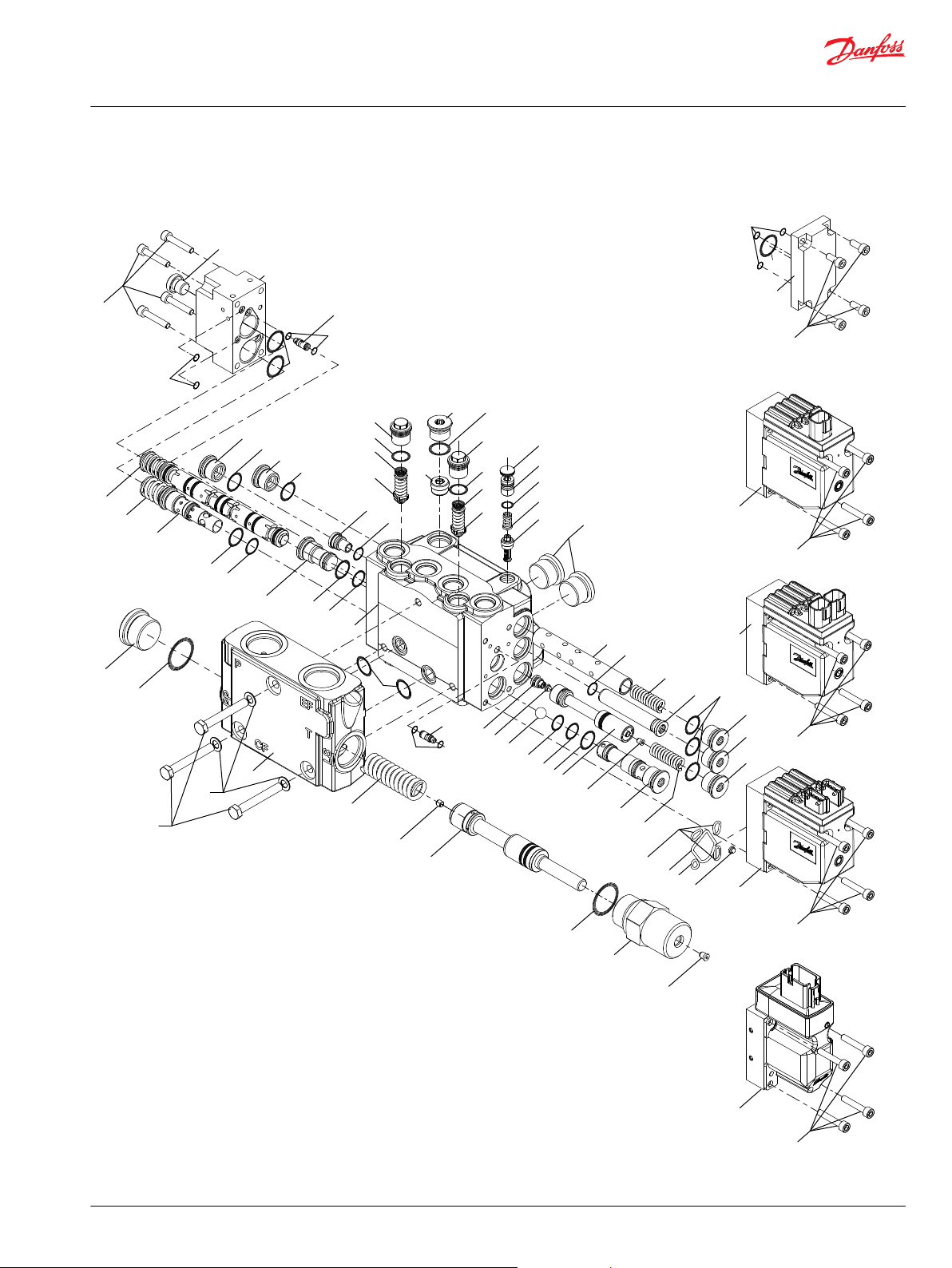
63b
110
6
112
111
1
61
16
4
21
80
2
8
82
80
15
20b
65
26
63a
91
3
95
81
9
85
20e
5
60
23
20c
7
25
94
62
81
82
114
70
70
20a
20d
22
201
201
201
201
201
201
202
203
202
204
204
205
205
201
202
206
66
67
Type 2, AMP
Type 2, DEUTSCH
Type 1, DEUTSCH
Type 0, Cover
63b
63b
6
6
6
6
61
62
90
Type 2, PVED-CLS
63b
207
207
P301 825
Service Manual
EHPS Steering Valve and OLS 320
Exploded view
EHPS type 0, 1 and 2 exploded view
6 | © Danfoss | July 2016 AX00000235en-US0102
Page 7

Service Manual
EHPS Steering Valve and OLS 320
Exploded view
EHPS spare parts list
EHPS spare parts
EHPS Number per unit Item Tigtening
Valve block 1 1 Spool with spring, directional 1 2 Spool with spring, pilot - OSP 1 3 Spool, meetering 1 4 Spring 1 5 PVE 1 6 Spool, priority valve 1 7 Orifice, Dynamic 1 8 3.5±0.5 Nm
Spring 1 9 Tube 1 15 10±0.5 Nm
Plug 1 16 10±0.5 Nm
Plug 1 20a 40±3 Nm
Plug 1 20b 40±3 Nm
Plug 1 20c 40±3 Nm
Plug 1 20d 40±3 Nm
Plug 1 20e 40±3 Nm
Bushing 1 21 40±3 Nm
Plug 1 22 40±3 Nm
Plug 1 23 40±3 Nm
Plug 1 25 20±3 Nm
Ball 1 26 Cover 1 60 O-ring Ø5.0 x Ø1.5 mm 5 61 O-ring Ø27.5 x Ø1.5 mm 3 62 Screw, M6, l=33 mm 4 63a 8±0.5 Nm
Screw, M6, l=33 mm 4 63b 8±0.5 Nm
Plug w. O-ring 1 65 Cover, EHPS type 0 1 66 Screw, M6, l=15 mm, EHPS type 0 4 67 8±0.5 Nm
Shuttle valve 2 70 Shock valve 2 80 Spring, conical 2 81 Plug 2 82 40±3 Nm
Check valve 1 85 25±5 Nm
Seat for pilot relief valve 1 90 20±3 Nm
Cone with spring for pilot relief valve 1 91 Adjusting screw for pilot relief valve 1 94 Plug 1 95 O-ring Ø10.0 x Ø2.0 mm 3 110 O-ring Ø30.0 x Ø2.5 mm 1 111 O-ring Ø8.0 x Ø2.0 mm 1 112 Filter 1 114 O-ring Ø17.4 x Ø2.1 mm 9 201 -
torque
©
Danfoss | July 2016 AX00000235en-US0102 | 7
Page 8
Service Manual
EHPS Steering Valve and OLS 320
Exploded view
EHPS spare parts (continued)
EHPS Number per unit Item Tigtening
O-ring Ø15.0 x Ø1.5 mm 3 202 O-ring Ø14.0 x Ø1.5 mm 1 203 O-ring Ø10.0 x Ø2.0 mm 2 204 O-ring Ø15.6 x Ø1.78 mm 2 205 O-ring Ø9.0 x Ø2.0 mm 1 206 O-ring Ø5.0 x Ø1.0 mm 4 207 -
torque
8 | © Danfoss | July 2016 AX00000235en-US0102
Page 9
110
112
111
10
1
16
4
21
80
8
304
310
82
80
15
20b
309
26
321
91
3
95
306
81
9
12
90
322
85
20e
307
323
5
23
20c
7
25
94
105
81
82
301
305
114
320
320
70
20a
20d
22
201
201
201
201
201
201
202
203
202
204
204
205
205
201
202
206
6
6
61
65
63a
60
62
70
207
2
66
67
Type 2, DEUTSCH
Type 1, DEUTSCH
Type 0, Cover
63b
63b
6
6
61
62
Type 2, PVED-CLS
63b
63b
Type 2, AMP
207
P301 826
Service Manual
EHPS Steering Valve and OLS 320
Exploded view
EHPS with flanged on OLS 320 exploded view
©
Danfoss | July 2016 AX00000235en-US0102 | 9
Page 10

Service Manual
EHPS Steering Valve and OLS 320
Exploded view
EHPS and OLS 320 spare parts list
EHPS spare parts
EHPS Number per unit Item Tigtening
Valve block 1 1 Spool with spring, directional 1 2 Spool with spring, pilot - OSP 1 3 Spool, meetering 1 4 Spring 1 5 PVE 1 6 Spool, priority valve 1 7 Orifice, Dynamic 1 8 3.5±0.5 Nm
Spring 1 9 Orifice, PP 1 10 3.5±0.5 Nm
Filter 1 12 Tube 1 15 10±0.5 Nm
Plug 1 16 10±0.5 Nm
Plug 1 20a 40±3 Nm
Plug 1 20b 40±3 Nm
Plug 1 20c 40±3 Nm
Plug 1 20d 40±3 Nm
Plug 1 20e 40±3 Nm
Bushing 1 21 40±3 Nm
Plug 1 22 40±3 Nm
Plug 1 23 40±3 Nm
Plug 1 25 20±3 Nm
Ball 1 26 Cover 1 60 O-ring Ø5.0 x Ø1.5 mm 5 61 O-ring Ø27.5 x Ø1.5 mm 3 62 Screw, M6, l=33 mm 4 63a 8±0.5 Nm
Screw, M6, l=33 mm 4 63b 8±0.5 Nm
Plug w. O-ring 1 65 Cover, EHPS type 0 1 66 Screw, M6, l=15 mm, EHPS type 0 4 67 8±0.5 Nm
Shuttle valve 2 70 Shock valve 2 80 Spring, conical 2 81 Plug 2 82 40±3 Nm
Check valve 1 85 25±5 Nm
Seat for pilot relief valve 1 90 20±3 Nm
Cone with spring for pilot relief valve 1 91 Adjusting screw for pilot relief valve 1 94 Plug 1 95 Plug 2 105 40±3 Nm
O-ring Ø10.0 x Ø2.0 mm 3 110 O-ring Ø30.0 x Ø2.5 mm 1 111 -
torque
10 | © Danfoss | July 2016 AX00000235en-US0102
Page 11

Service Manual
EHPS Steering Valve and OLS 320
Exploded view
EHPS spare parts (continued)
EHPS Number per unit Item Tigtening
O-ring Ø8.0 x Ø2.0 mm 1 112 Filter 1 114 O-ring Ø17.4 x Ø2.1 mm 9 201 O-ring Ø15.0 x Ø1.5 mm 3 202 O-ring Ø14.0 x Ø1.5 mm 1 203 O-ring Ø10.0 x Ø2.0 mm 2 204 O-ring Ø15.6 x Ø1.78 mm 2 205 O-ring Ø9.0 x Ø2.0 mm 1 206 O-ring Ø5.0 x Ø1.0 mm 4 207 -
OLS 320 spare parts
OLS 320 Number per unit Item Tightening
Housing 1 301 Spool 1 304 Orifice, LS 1 305 1±0.1 Nm
Orifice, PP 1 306 3.5±0.5 Nm
Spring 1 307 Plug, LS 1 309 50±5 Nm
Plug. PP 1 310 50±5 Nm
O-ring Ø29.6 x Ø2.9 mm 2 320 O-ring Ø16.0 x Ø2.5 mm 2 321 Screw 3 322 28±2 Nm
Washer 3 323 -
torque
torque
Seal kits and spare parts for EHPS and OLS 320
Spare parts list Code No. Item
Seal kit, EHPS 150H4021 61, 62, 201, 202, 203, 204, 205, 206, 207
Seal kit OLS 320 152B6200 320
Seal kit for block ass. 11008362 321
Seal kit for PVE/cover 157B4997 110, 111, 112, 114
Shuttle valve, 2 pcs 11007949 70
©
Danfoss | July 2016 AX00000235en-US0102 | 11
Page 12
150H11.11
78[3.07]
47.5[1.870] 47.5[1.870]
83.5[3.287]
22.5[0.886]
B
68[2.68]
14[0.55]
47.5[1.870]47.5[1.870]
4.3[0.17]
83.5[3.287]
A
Service Manual
EHPS Steering Valve and OLS 320
Tools
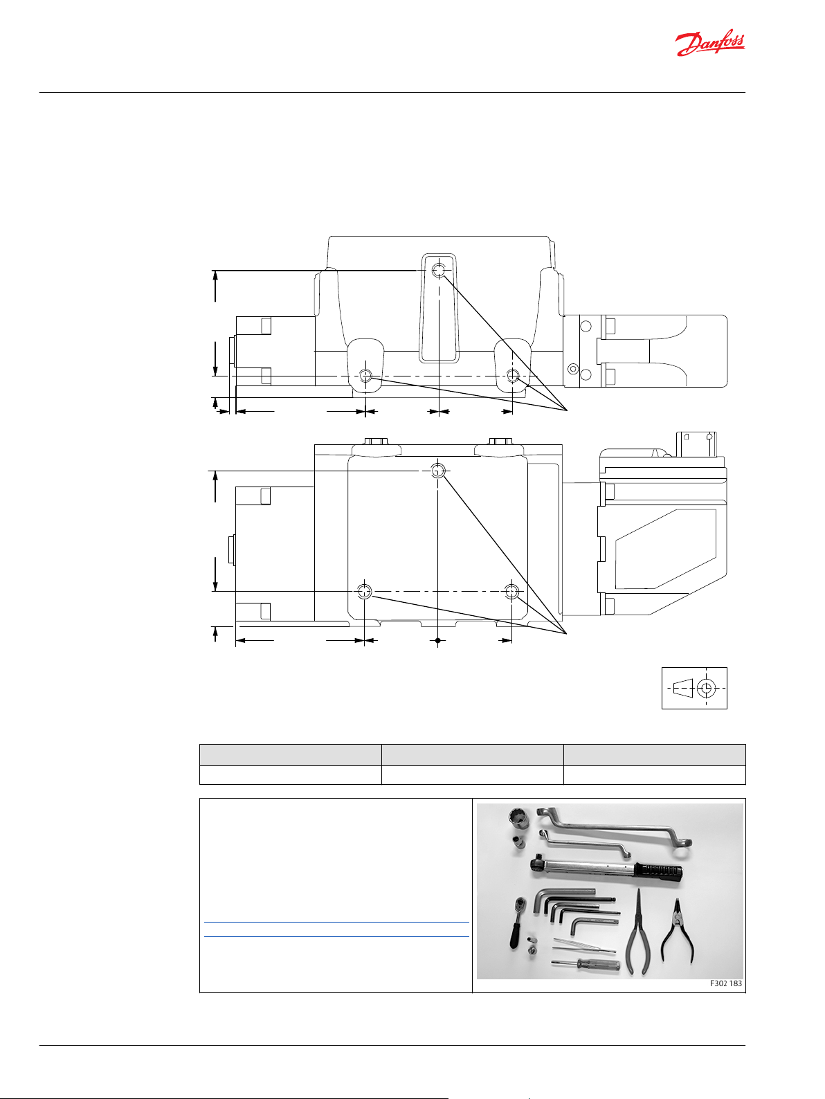
Tools for EHPS
Holding tool: It is recommended to use appropriate steel plate with mounting holes 3x Ø 10 mm
matching mounting thread holes, A or B on one of the two mounting sides of EHPS.
All versions M8 • 1.25, 10 mm [0.39 in] deep M8 • 1.25, 10 mm [0.39 in] deep
Torque wrench 0 - 70 Nm.
6 and 13 mm socket spanner.
5, 2x 8, 12 and 14 mm Hex keys.
T50 Torx key
2 mm screwdriver.
13 – 17 – 19 – 36 – 41 mm ring spanner.
Pliers
Inside circlip pliers.
Tweezers
These tools are not available from Danfoss.
A B
12 | © Danfoss | July 2016 AX00000235en-US0102
Page 13
Service Manual
EHPS Steering Valve and OLS 320
Disassembly and assembly
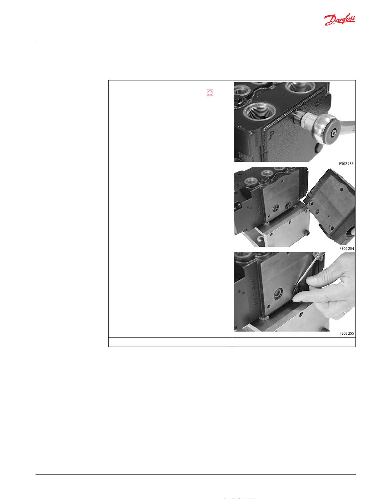
Disassembly of EHPS
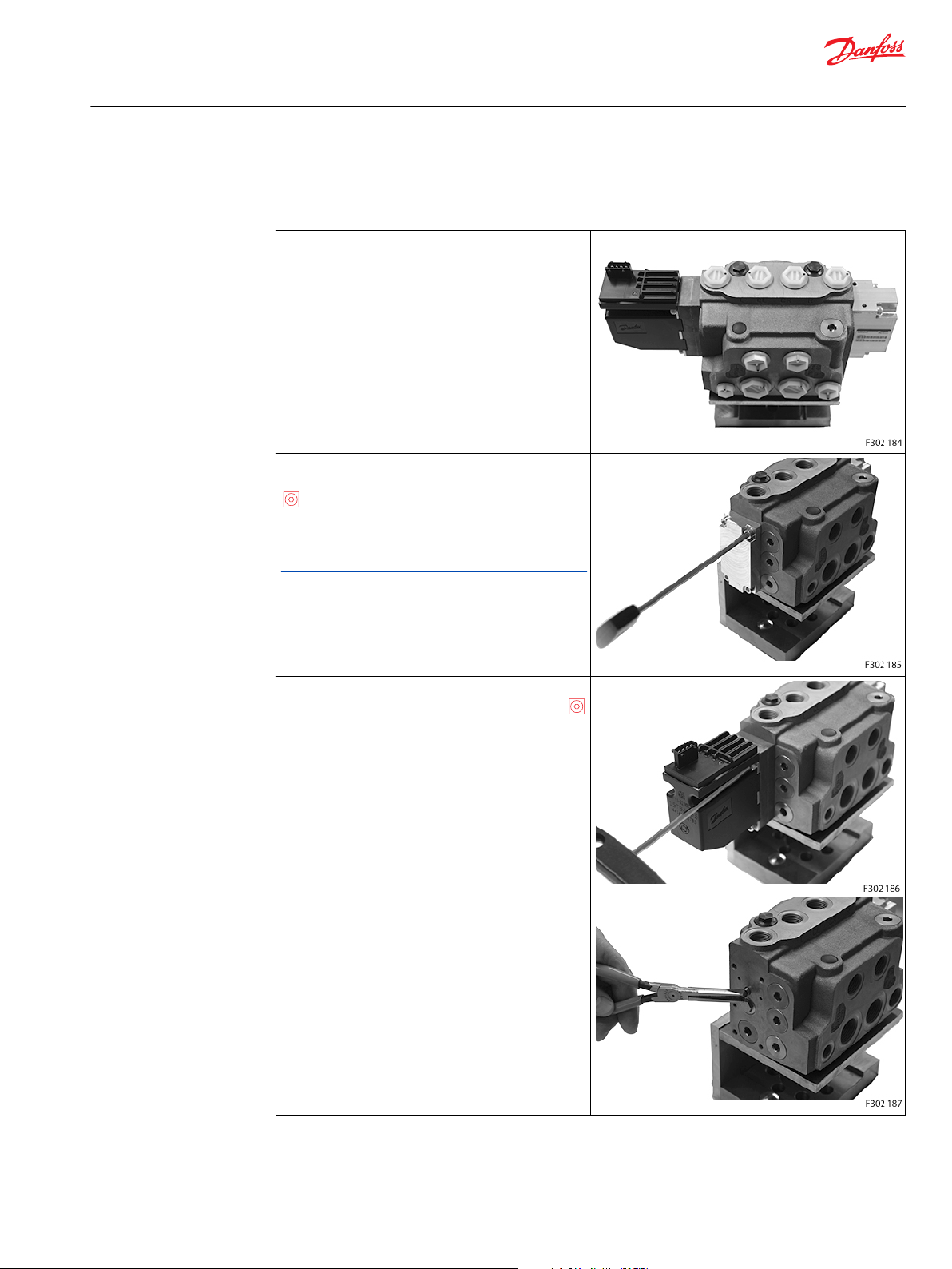
Disassembly of EHPS
Place the unit on the holding tool.
EHPS type 0 (without PVE):
Screw out the 4 screws (67) for cover (66) using a 5 mm
Hex key.
Remove the cover (66).
O-rings (61 and 62) are fitted to cover (66).
Shuttle valves (70) are not present in EHPS type 0.
EHPS type 1 and type 2:
Screw out the 4 screws (63b) for PVE (6) using a 5 mm
Hex key.
Remove the PVE (6).
O-rings (110, 111 and 112) and filter (114) are fitted to the
mounting surface of PVE.
Shuttle valve (70) is fitted into the mounting surface of
PVE (6) and housing (1), it will stay in one of the 2
elements when removing the PVE from the EHPS
housing.
©
Danfoss | July 2016 AX00000235en-US0102 | 13
Page 14
Service Manual
EHPS Steering Valve and OLS 320
Disassembly and assembly
Disassembly of EHPS (continued)
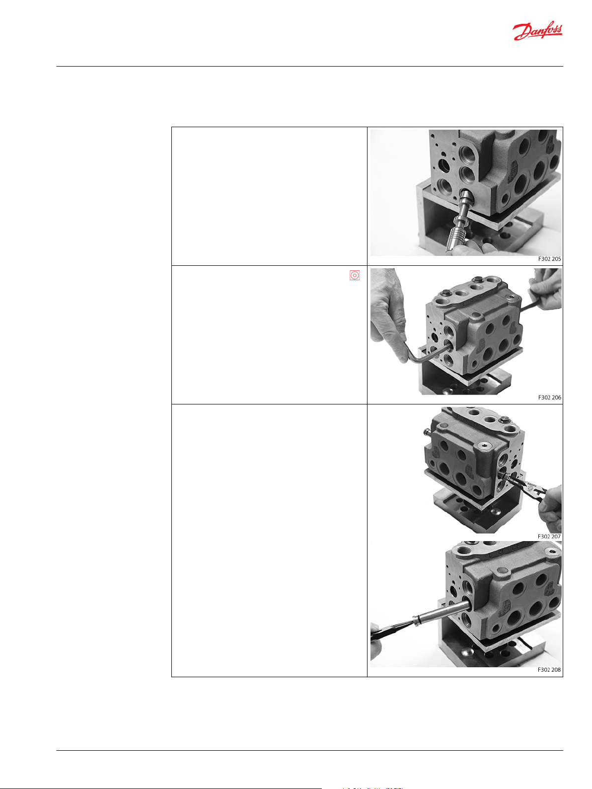
Screw out the plug (25) using an 8 mm Hex key.
O-rings (201, 202 and 203) are fitted to the bushing (21).
Remove the ball (26).
Screw out the plugs (20c, 20d and 22) using an 8 mm
Hex key.
O-rings (201) are fitted to the plugs.
14 | © Danfoss | July 2016 AX00000235en-US0102
Page 15
Service Manual
EHPS Steering Valve and OLS 320
Disassembly and assembly
Disassembly of EHPS (continued)
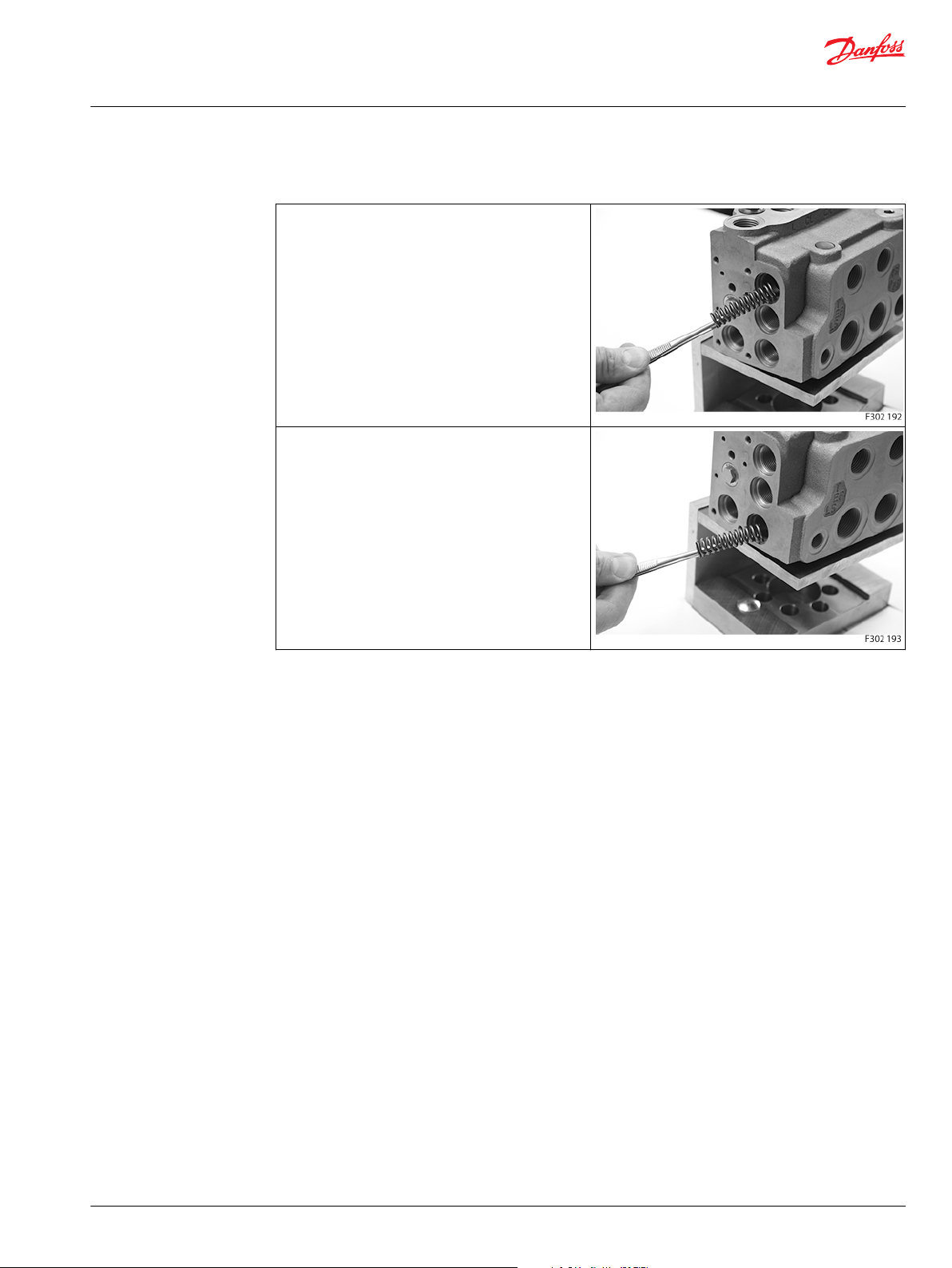
Remove the spring (5).
Remove the spring (9).
©
Danfoss | July 2016 AX00000235en-US0102 | 15
Page 16

Service Manual
EHPS Steering Valve and OLS 320
Disassembly and assembly
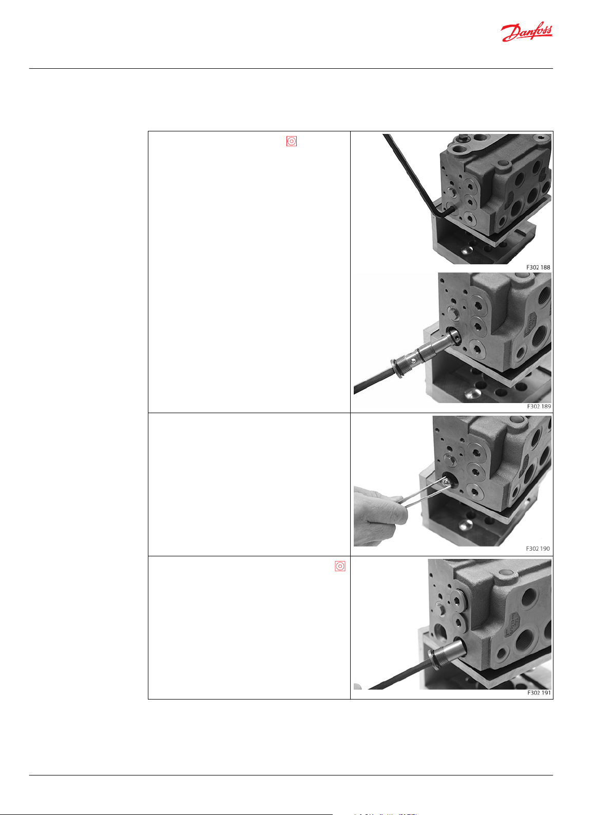
Disassembly of EHPS (continued)
Screw out the 4 screws (63a) for cover (60) using a 5 mm
Hex key.
Remove the cover (60).
O-rings (61 and 62) are fitted to the mounting surface of
cover.
EHPS type 1 and 2:
Shuttle valve (70) is fitted into the mounting surface of
cover (60) and housing (1), it will stay in one of the 2
elements when removing the cover from the EHPS
housing.
Plug (65) is fitted to cover (60). It is recommended not to
screw out plug (65).
EHPS type 0 normally has no shuttle valves (70).
Remove the directional spool with spring (2).
16 | © Danfoss | July 2016 AX00000235en-US0102
Page 17

Service Manual
EHPS Steering Valve and OLS 320
Disassembly and assembly
Disassembly of EHPS (continued)
Remove the pilot spool with spring (3).
Screw out the bushing (21) using a 12 mm Hex key.
O-rings (201 and 202) are fitted to the bushing (21).
©
Danfoss | July 2016 AX00000235en-US0102 | 17
Page 18

Service Manual
EHPS Steering Valve and OLS 320
Disassembly and assembly
Disassembly of EHPS (continued)
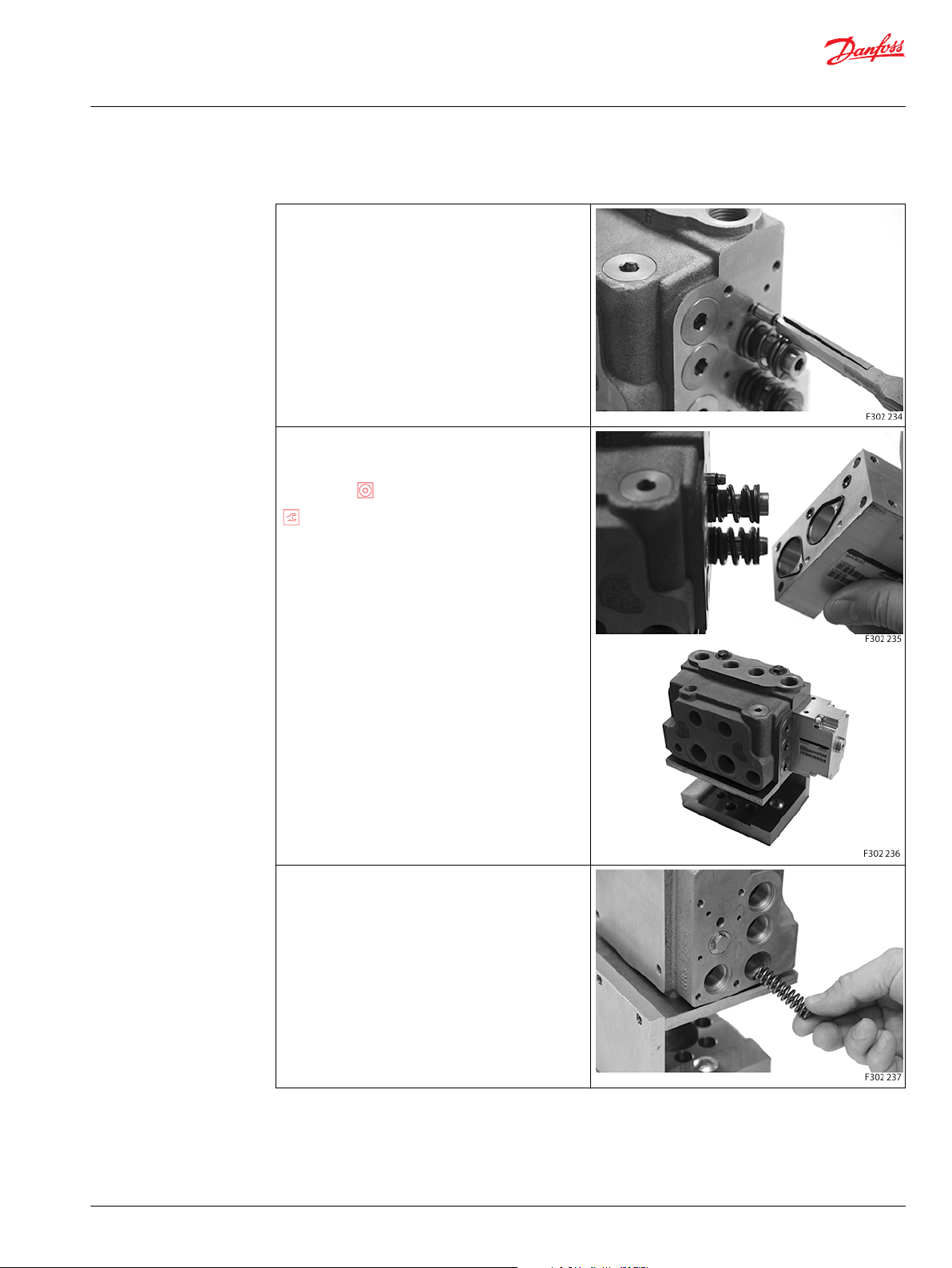
Screw out the plugs (20a, 20b and 23) using an 8 mm
Hex key.
O-rings (201) are fitted to the plugs (20a and 20b). Orings (201 and 202) are fitted to the plug (23).
From the PVE end (type 1 and 2) or cover (66) end (type
0):
Remove the meetering spool (4).
18 | © Danfoss | July 2016 AX00000235en-US0102
Page 19
Service Manual
EHPS Steering Valve and OLS 320
Disassembly and assembly
Disassembly of EHPS (continued)
Remove the priority valve spool (7).
Orifice, dynamic (8) is screwed into spool (7).
Screw out the plug (16) of tube (15) using two 8 mm
Hex keys: one in plug and one in tube end.
Remove plug (16) and tube (15).
O-rings (204) are fitted to the plug (16) and the tube (15).
©
Danfoss | July 2016 AX00000235en-US0102 | 19
Page 20

Service Manual
EHPS Steering Valve and OLS 320
Disassembly and assembly
Disassembly of EHPS (continued)
Screw out the plugs (82) using a 13 mm socket or
ring spanner.
O-rings (205) are fitted to the plugs (82).
Remove the shock valves (80) with conical springs (81).
Screw out the plug (20e) using an 8 mm Hex key.
O-ring (201) is fitted to the plug (20e)
20 | © Danfoss | July 2016 AX00000235en-US0102
Page 21

Service Manual
EHPS Steering Valve and OLS 320
Disassembly and assembly
Disassembly of EHPS (continued)
Screw out the check valve (85) using an T50 Torx key.
Remove plug (95) using a 2 mm screw driver.
Screw out the adjusting screw (94) using an 6 mm
Hex key.
O-ring (206) is fitted to the screw (94).
©
Danfoss | July 2016 AX00000235en-US0102 | 21
Page 22

Service Manual
EHPS Steering Valve and OLS 320
Disassembly and assembly
Disassembly of EHPS (continued)
Remove the spring with cone (91).
Screw out the seat (90) using a 6 mm socket spanner.
Now the EHPS is completely dismantled.
Cleaning: Clean all parts carefully in Shellsol K or similar cleaner fluid.
Inspection and replacement: Replace all seals and washers.
Check all parts carefully and make any replacements as is necessary.
22 | © Danfoss | July 2016 AX00000235en-US0102
Page 23

Service Manual
EHPS Steering Valve and OLS 320
Disassembly and assembly
Assembly of EHPS
Assembly of EHPS
Place the housing on the holding tool.
Screw in the seat (90) using a 6 mm socket spanner.
20 ±3 Nm.
Place the spring with cone (91).
Place O-ring (206) on screw (94).
Screw in the adjusting screw (94) using an 6 mm Hex
key.
After entire assembly of the steering valve, make the
pressure setting on a test panel according to valve
setting specification, see Testing of EHPS on page 39.
Insert plastic protection plug (95).
©
Danfoss | July 2016 AX00000235en-US0102 | 23
Page 24

Service Manual
EHPS Steering Valve and OLS 320
Disassembly and assembly
Assembly of EHPS (continued)
Screw in the check valve (85) using an T50 Torx key.
25 ±5 Nm.
Place O-ring (201) on to the plug (20e). Screw in the plug
(20e) using an 8 mm Hex key.
40 +/- 3 Nm.
Insert the shock valves (80) with conical springs (81).
Place O-rings (205) on the plugs (82).
Screw in the plugs (82) using a 13 mm socket or ring
spanner.
40 ±3 Nm.
24 | © Danfoss | July 2016 AX00000235en-US0102
Page 25

Service Manual
EHPS Steering Valve and OLS 320
Disassembly and assembly
Assembly of EHPS (continued)
Place O-rings (204) on the plug (16) and the tube (15).
Insert plug (16) and tube (15) and tighten using two 8
mm Hex keys: one in plug and one in tube end.
10 ±0.5 Nm.
Assemble priority valve spool (7) with the dynamic orifice
(8) using a 3 mm Hex key.
3.5 ±0.5 Nm.
Insert the priority valve spool (7) with the spring bore
pointing outwards.
Insert the meetering spool (4) with the spring bore
pointing outwards/flat end pointing inwards.
©
Danfoss | July 2016 AX00000235en-US0102 | 25
Page 26

Service Manual
EHPS Steering Valve and OLS 320
Disassembly and assembly
Assembly of EHPS (continued)
From the end cover (60) end:
Place O-ring (201) on to the plugs (20a and 20b, the two
upper plugs).
Place O-rings (201 and 202) on the plug (23, the lower
plug).
Screw in the plug (20a, 20b and 23) using an 8 mm
Hex key.
40 ±3 Nm.
Place O-rings (201 and 202) to the bushing (21). Screw in
the bushing (21) using a 12 mm Hex key.
40 ±3 Nm.
Insert the pilot spool w. spring (3).
Insert the directional spool w. spring (2).
26 | © Danfoss | July 2016 AX00000235en-US0102
Page 27
Service Manual
EHPS Steering Valve and OLS 320
Disassembly and assembly
Assembly of EHPS (continued)
If it concerns EHPS type 1 or type 2 it has 2x shuttle
valves.
Place 2x O-rings (207) on each shuttle valves (70).
Insert the shuttle valve (70).
Place O-rings (2x 61 and 2x 62) on the mounting surface
of cover (60).
Place the cover (60) on housing with the 4 screws (63a)
using a 5 mm Hex key.
8 ±0.5 Nm.
From the PVE end (type 1 and 2) or cover (66) end (type
0):
Insert the spring (9) for priority valve.
©
Danfoss | July 2016 AX00000235en-US0102 | 27
Page 28
Service Manual
EHPS Steering Valve and OLS 320
Disassembly and assembly
Assembly of EHPS (continued)
Insert the spring (5) for metering valve.
Place O-ring (201) on to the plugs (22, the lower) (20c and
20d, the two upper short plugs).
Screw in the plug (20c, 20d and 22) using an 8 mm
Hex key.
40 ±3 Nm
Insert the ball (26).
28 | © Danfoss | July 2016 AX00000235en-US0102
Page 29

Service Manual
EHPS Steering Valve and OLS 320
Disassembly and assembly
Assembly of EHPS (continued)
Place O-ring (201, 202 and 203) plug (25).
Screw in the plug (25) using an 8 mm Hex key.
40 ±3 Nm.
EHPS type 0 (without PVE):
Place O-rings (1x 62 and 3x 61) on the mounting surface
of cover (66).
Place the cover (66) on housing with the 4 screws (67)
using a 5 mm Hex key.
8 ±0.5 Nm.
If it concerns EHPS type 1 or type 2 it has 2x shuttle
valves.
Place 2x O-rings (207) on each shuttle valves (70).
Insert the shuttle valve (70).
©
Danfoss | July 2016 AX00000235en-US0102 | 29
Page 30

Service Manual
EHPS Steering Valve and OLS 320
Disassembly and assembly
Assembly of EHPS (continued)
EHPS type 1 or 2 (with PVE):
Place O-rings (3x 110, 1x 111, 1x 112 and 1x filter 114) on
the mounting surface of PVE (6).
Place the PVE (6) on housing with the 4 screws (63b)
using a 5 mm Hex key.
8 ±0.5 Nm
Make test and valve setting according to Testing of EHPS
on page 39.
Screw in the plastic plugs into the connection ports to
keep the ports clean during storage and transportation.
30 | © Danfoss | July 2016 AX00000235en-US0102
Page 31

Service Manual
EHPS Steering Valve and OLS 320
Disassembly and assembly
Disassembly of OLS 320 and priority valve spool of EHPS
This section only describes the dismantling and assembling of parts, which differs from EHPS type 0, 1
and 2. The item numbers refers to EHPS with flanged on OLS 320 exploded view on page 9.
Disassembly of OLS 320
Place the unit on the holding tool.
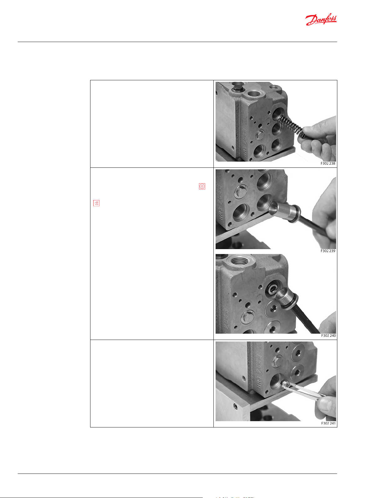
Screw out the LS orifice (305) using a 2 mm Hex key,
if present.
Some versions of LS plug for OLS 320 has integrated LS
orifice in the plug (309 as in this case), and some LS plugs
are blind plugs.
Screw out the LS plug (309) using a 41 mm socket or
ring spanner.
O-ring (320) is fitted to the plug (309).
Remove the spring (307).
©
Danfoss | July 2016 AX00000235en-US0102 | 31
Page 32

Service Manual
EHPS Steering Valve and OLS 320
Disassembly and assembly
Disassembly of OLS 320 (continued)
Screw out the LS plug (310) using a 14 mm Hex key.
O-ring (320) is fitted to the plug (310).
Remove the priority valve spool (304).
Orifice, PP (306) is screwed into spool (304).
32 | © Danfoss | July 2016 AX00000235en-US0102
Page 33
Service Manual
EHPS Steering Valve and OLS 320
Disassembly and assembly
Disassembly of OLS 320 (continued)
Remove the OLS 320 housing (301) from the EHPS by
unscrewing the 3 screws (322) using a 13 mm socket
or ring spanner.
3 washers (323) are fitted to the screws (322).
2 O-rings (321) are fitted to the EHPS-housing (1).
Now the OLS 320 is completely dismantled
©
Danfoss | July 2016 AX00000235en-US0102 | 33
Page 34

Service Manual
EHPS Steering Valve and OLS 320
Disassembly and assembly
Disassembly of EHPS
Screw out the plug (22) using an 8 mm Hex key.
O-ring (201) is fitted to the plug.
Remove the spring (9).
Screw out the plug (23) using an 8 mm Hex key.
O-rings (201and 202) are fitted to the plug (23).
34 | © Danfoss | July 2016 AX00000235en-US0102
Page 35

Service Manual
EHPS Steering Valve and OLS 320
Disassembly and assembly
Disassembly of EHPS (continued)
Remove the priority valve spool (7).
Orifice, dynamic (8), orifice, PP (10) and are screwed into
spool (7).
Filter (12) is fitted into the spool (7).
All other EHPS parts are the same for EHPS “ stand alone”
and for EHPS for OLS 320.
Cleaning: Clean all parts carefully in Shellsol K or similar cleaner fluid.
Inspection and replacement Replace all seals and washers.
Assembly of OLS 320 and priority valve spool of EHPS
Assembly of OLS 320 and priority valve spool of EHPS
Place the EHPS housing on the holding tool.
Assemble all parts for EHPS, see Assembly of EHPS on
page 23.
Check all parts carefully and make any replacements as is necessary.
©
Danfoss | July 2016 AX00000235en-US0102 | 35
Page 36

Service Manual
EHPS Steering Valve and OLS 320
Disassembly and assembly
OLS parts for EHPS for OLS 320:
From the end cover (60) end:
Place O-rings (201 and 202) on the plug (23, the lower
plug).
Screw in the plug (23) using an 8 mm Hex key.
40 ±3 Nm.
Assemble priority valve spool (7) with:
The dynamic orifice (8) using a 3 mm Hex key,
3.5 ±0.5 Nm.
The filter (12) to be inserted.
The PP orifice (10) using a 4 mm Hex key, 3.5
±0.5 Nm.
From the PVE end (type 1 and 2) or cover (66) end (type
0):
Insert the priority valve spool (7) with the spring bore
pointing outwards.
Insert the spring (9) for priority valve.
Place O-ring (201) on to the plugs (22, the lower).
Screw in the plug (22) using an 8 mm Hex key.
40 ±3 Nm
36 | © Danfoss | July 2016 AX00000235en-US0102
Page 37

Service Manual
EHPS Steering Valve and OLS 320
Disassembly and assembly
OLS parts for EHPS for OLS 320: (continued)
Flange the OLS 320 housing (301) on the EHPS housing
(1):
Insert the two O-rings (321) in the EHPS housing (1)
indicated in circle Fit the three screws (322) with washers
(323) and insert them.
Use a 13 mm top wrench, 28 ±2 Nm.
Place O-ring (320) on the plug (310).
Screw in the plug (320) using a 14 mm Hex key.
50 ±5 Nm
Assemble priority valve spool (304) with:
The PP orifice (306) using a 3 mm Hex key, 3,5
±0.5 Nm.
Insert the priority valve spool (304) with the spring guide
pointing outwards.
©
Danfoss | July 2016 AX00000235en-US0102 | 37
Page 38

Service Manual
EHPS Steering Valve and OLS 320
Disassembly and assembly
OLS parts for EHPS for OLS 320: (continued)
Insert the spring (307) for priority valve.
Place O-ring (320) on the plug (309).
Screw in the plug (320) using a 41 mm socket
spanner, 50 ±5 Nm
If present: Screw in the LS orifice (305) using a 2 mm
Hex key, 1 ±0.1 Nm.
Some versions of LS plug for OLS 320 integrated LS
orifice in the plug (305, as in this case), and some LS plugs
are blind plugs.
To make test and valve setting, see Testing on page 39.
Screw in the plastic plugs into the connection ports to
keep the ports clean during storage and transportation.
38 | © Danfoss | July 2016 AX00000235en-US0102
Page 39

T
P
P301 827.10
OSPCX CN
L
P
T
R
PVRES
EHPS
CL
R
CR
L
Ps
Ts
type 1
EF LS
Electronics
1
2
TE
3
PE
RE
LE
4
PVES
Service Manual
EHPS Steering Valve and OLS 320
Testing
Testing of EHPS
This section describes minimum tests needed, when the EHPS steering valve has been disassembled and
reassembled.
EHPS type 1 with PVES:
Set up for testing the EHPS
Use universal hydraulic work bench with pump capacity:
•
40 l/min and up to 250 bar pressure for relief valve setting and steering test
The hydraulic oil must be with a viscosity of 21 cSt. at 50 ° and with max. degree of contamination
according to ISO 4406: 21 / 19 / 16.
1. Connect double rod cylinder to CL and CR ports of EHPS.
2. Connect pilot steering unit OSPCX CN to EHPS: L to L, R to R, P to Ps, T to Ts.
3. Connect T and EF port of EHPS to tank of pump station.
4. With fixed gear pump in pump station: Block LS of EHPS with steel plug. With LS pump in pump
5. Connect pressure gages to all ports of EHPS.
6. Connect steering column and steering wheel to the input shaft of the OSPCX steering unit.
7. For EHPS with PVES, PVED CC, PVED CL, after steering wheel test (test with pilot steering unit, type
T pressure should not exceed ~5 bar. Max. allowed T pressure is 25 bar.
Pump supply circuit must be adjusted not to exceed 250 bar P-T.
Steering test using pilot steering unit type OSPCX CN
During the testing no motor effect, disturbing vibrations, noise, sticking or other irregularities must occur.
1. Start the pump, the pump flow is adjusted to approx. 40 l/min and pump pressure control must be
©
Danfoss | July 2016 AX00000235en-US0102 | 39
station: connect LS of EHPS to LS of pump. Connect P to pump outlet.
OSPCX CN): Connect voltage supply and signal input for the PVE.
set to app. 70 bar.
Page 40

Service Manual
EHPS Steering Valve and OLS 320
Testing
2. Let the supplied oil flow through the EHPS for a few minutes. At the same time the steering wheel is
to be rotated a few times in both directions to bleed of air from the unit and the system.
3. Operate the steering wheel by approx. 10 rpm in a smooth manner from end stroke to end stroke of
the steering cylinder for at least 5 cycles. Make sure pressure P-T, 70 bar can be achieved, when
steering against end stroke. If this is not possible, the adjusting screw of the pilot relief valve (item 94
of exploded view) must be turned clockwise until P-T, 70 bar is achievable.
4. Verify, that steering cylinder does not move, when steering wheel is untouched.
The number of turns i on steering wheel must match this calculation: i ~= V/Vvs where:
•
V is stroke volume of steering cylinder, ccm
•
Vvs = EHPS steering system displacement, ccm/rev.
This calculation will only match, when pump flow is sufficient for the actual steering speed. Pump flow
must be minimum sum of cylinder flow (CQ, flow metered to steering cylnder) and pilot flow (PQ, flow
from pilot steering unit).
V, stroke volume if cylinder in test rig: 1600 ccm
Vvs, steering system displacement with EHPS 40/5 and OSPCX 50 CN: 400 ccm/rev
>
i ~= 1600/400 4 turns lock to lock
Pilot relief valve for EHPS
The pump flow is adjusted to approx. 40 l/min and pump pressure to max 250 bar.
The steering wheel is actuated until the steering cylinder reaches one of its end strokes and the steering
wheel is actuated in this cylinder position with steering torque 20 ±5 Nm.
The pilot relief valve (item 94 of exploded view) is set according to specification: Max. steering pressure
(P-T), bar, for the code in question.
The setting pressure is the pressure on the P-port minus the T-port of EHPS.
Neutral positioning test, OSP part for EHPS
After adjusting the pilot relief valve, the steering wheel must be able to go to neutral position by itself no
later than ~1 second after the activation of the steering wheel has been stopped.
The steering unit and EHPS is proper in neutral position when the pressure drop (P-T of EHPS) is no higher
than 30 bar at pump flow 40 l/min, and there must be no movement of the steering cylinder.
Steering and neutral positioning test, EH part with EHPS
For EHPS with PVES, PVED CC, PVED CL: Apply battery power and input signal to the PVE: observe that the
steering cylinder is moving according to direction of input signal for PVE. Observe that max steering
pressure (P-T) from above setting can be reach, when steering cylinder is moved to full end stroke by the
PVE. Apply neutral position signal for PVE, observe that cylinder movement stops and that pressure P-T
drops to max. 30 bar at pump flow 40 l/min.
Manual steering with EHPS
Without pressure on P and T ports, the OSPCX and EHPS must be able to steer in a smooth manner to the
right and to the left observed by the cylinder movement. The number of turns on the steering wheel for
moving the steering cylinder from lock to lock, must increase in comparison to do this test with normal
pump supply.
Without pump supply the number of turns must match cylinder volume/displacement of OSPCX.
Example: Cylinder volume: 1600 ccm, and OSPCX 50 CN > Number of turns must be 1600/50 ~= 32 turns.
40 | © Danfoss | July 2016 AX00000235en-US0102
Page 41

P301 828.10
EF
EF
Ts
LS
LS
P
OLS
320
T
CL CR
EHPS
type 0
OSPCX CN
L
P
T
R
R
L
Ps
P
Service Manual
EHPS Steering Valve and OLS 320
Testing
Testing of EHPS with OLS 320
Testing of EHPS with OLS 320
Set up for testing the EHPS with OLS 320
Setup and testing for EHPS w. OLS 320 will be the same as for EHPS “stand alone” except:
•
P from pump station is connected to P of OLS 320
•
EF of OLS 320 to T of pump station
•
LS of OLS 320 to LS of EHPS.
©
Danfoss | July 2016 AX00000235en-US0102 | 41
Page 42

Service Manual
EHPS Steering Valve and OLS 320
42 | © Danfoss | July 2016 AX00000235en-US0102
Page 43

Service Manual
EHPS Steering Valve and OLS 320
©
Danfoss | July 2016 AX00000235en-US0102 | 43
Page 44

Danfoss
Power Solutions GmbH & Co. OHG
Krokamp 35
D-24539 Neumünster, Germany
Phone: +49 4321 871 0
Danfoss
Power Solutions ApS
Nordborgvej 81
DK-6430 Nordborg, Denmark
Phone: +45 7488 2222
Danfoss
Power Solutions (US) Company
2800 East 13th Street
Ames, IA 50010, USA
Phone: +1 515 239 6000
Danfoss
Power Solutions Trading
(Shanghai) Co., Ltd.
Building #22, No. 1000 Jin Hai Rd
Jin Qiao, Pudong New District
Shanghai, China 201206
Phone: +86 21 3418 5200
Products we offer:
Comatrol
www.comatrol.com
Schwarzmüller-Inverter
www.schwarzmuellerinverter.com
Turolla
www.turollaocg.com
Hydro-Gear
www.hydro-gear.com
Daikin-Sauer-Danfoss
www.daikin-sauer-danfoss.com
Bent Axis Motors
•
Closed Circuit Axial Piston
•
Pumps and Motors
Displays
•
Electrohydraulic Power
•
Steering
Electrohydraulics
•
Hydraulic Power Steering
•
Integrated Systems
•
Joysticks and Control
•
Handles
Microcontrollers and
•
Software
Open Circuit Axial Piston
•
Pumps
Orbital Motors
•
PLUS+1® GUIDE
•
Proportional Valves
•
Sensors
•
Steering
•
Transit Mixer Drives
•
Danfoss Power Solutions is a global manufacturer and supplier of high-quality hydraulic and
electronic components. We specialize in providing state-of-the-art technology and solutions
that excel in the harsh operating conditions of the mobile off-highway market. Building on
our extensive applications expertise, we work closely with our customers to ensure
exceptional performance for a broad range of off-highway vehicles.
We help OEMs around the world speed up system development, reduce costs and bring
vehicles to market faster.
Danfoss – Your Strongest Partner in Mobile Hydraulics.
Go to www.powersolutions.danfoss.com for further product information.
Wherever off-highway vehicles are at work, so is Danfoss. We offer expert worldwide support
for our customers, ensuring the best possible solutions for outstanding performance. And
with an extensive network of Global Service Partners, we also provide comprehensive global
service for all of our components.
Please contact the Danfoss Power Solution representative nearest you.
Local address:
Danfoss can accept no responsibility for possible errors in catalogues, brochures and other printed material. Danfoss reserves the right to alter its products without notice. This also applies to products
already on order provided that such alterations can be made without changes being necessary in specifications already agreed.
All trademarks in this material are property of the respective companies. Danfoss and the Danfoss logotype are trademarks of Danfoss A/S. All rights reserved.
©
Danfoss | July 2016 AX00000235en-US0102
 Loading...