

Page 1
MAKING MODERN LIVING POSSIBLE
Technical Information
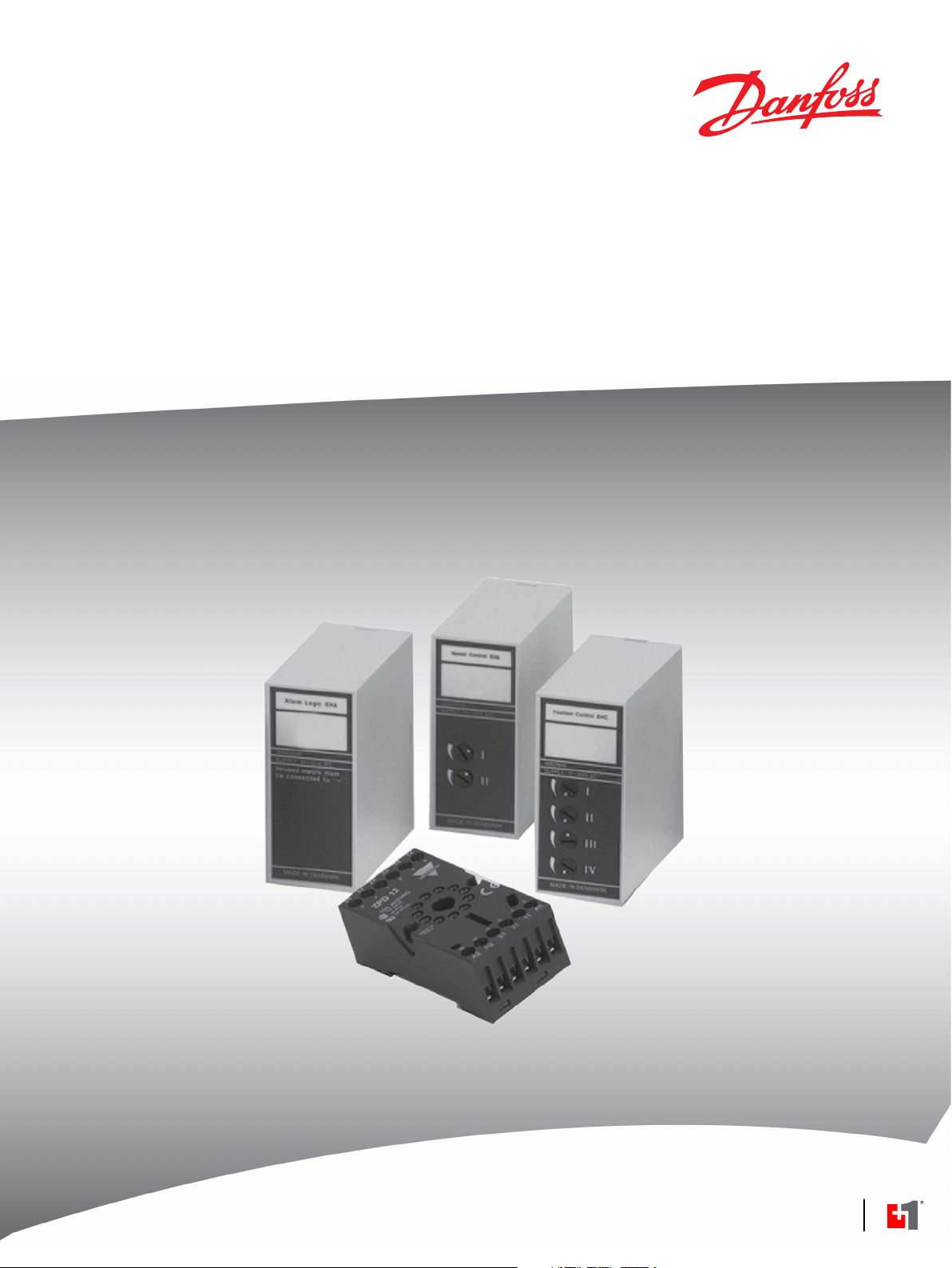
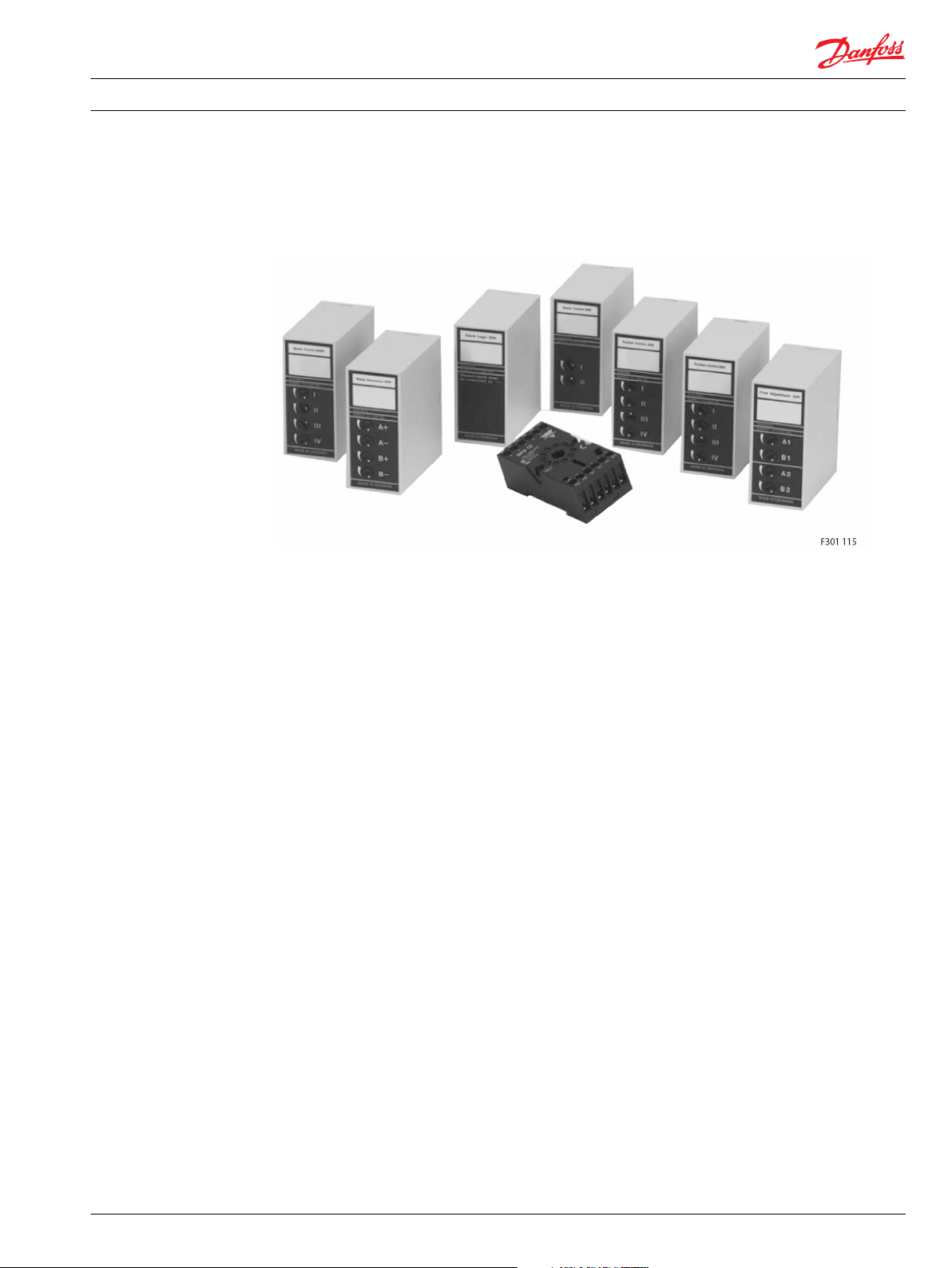
Electronic Control Modules
EH Modules
powersolutions.danfoss.com
Page 2

Technical Information EH Modules
Revision history Table of revisions
Date Changed Rev
January 2016 Converted to Danfoss layout 0103
September 2010 New Back cover AC
May 2010 Japan location AB
October 2004 First edition A
2 520L0804 • Rev 0103 • January 2016
Page 3

Technical Information
EH Modules
Contents
Electronic control modules - EH modules
General.................................................................................................................................................................................................5
Mounting base and accessories - EHB
General.................................................................................................................................................................................................6
Dimensions, code numbers, and weight................................................................................................................................. 7
Electronic flow regulation - EHF
General ................................................................................................................................................................................................8
Function...............................................................................................................................................................................................8
Signal monitoring.............................................................................................................................................................................9
Characteristic..................................................................................................................................................................................... 9
Electrical system ............................................................................................................................................................................10
Technical data................................................................................................................................................................................. 10
Code number and weight...........................................................................................................................................................11
Electronic alarm logic - EHA
General ..............................................................................................................................................................................................12
Function............................................................................................................................................................................................ 13
Electrical system.............................................................................................................................................................................14
Monitoring more than eight functions.................................................................................................................................. 15
Electric remote to mechanical operation..............................................................................................................................16
Technical data................................................................................................................................................................................. 17
Code number and weight...........................................................................................................................................................17
Electronic ramp generator - EHR
General ..............................................................................................................................................................................................18
Function............................................................................................................................................................................................ 18
Signal monitoring..........................................................................................................................................................................19
Electrical system - Principle 1.....................................................................................................................................................20
Electrical system - Principle 2.....................................................................................................................................................21
Ramp times.......................................................................................................................................................................................22
External break contacts................................................................................................................................................................23
KA, KB signals...................................................................................................................................................................................23
Technical data................................................................................................................................................................................. 24
Code number and weight...........................................................................................................................................................24
Electronic speed control - EHS
General ..............................................................................................................................................................................................25
Function............................................................................................................................................................................................ 25
Potentiometer 1..............................................................................................................................................................................26
Potentiometer 2..............................................................................................................................................................................26
Potentiometer (P)...........................................................................................................................................................................27
Recommendation.......................................................................................................................................................................... 27
Input reference............................................................................................................................................................................... 27
Electrical connection.................................................................................................................................................................... 29
Technical data................................................................................................................................................................................. 29
Code number and weight...........................................................................................................................................................30
Electronic, frequency controlled loop speed control - EHSC
General ..............................................................................................................................................................................................31
Adjustment possibilities..............................................................................................................................................................31
Function monitoring.....................................................................................................................................................................32
Adjustments.....................................................................................................................................................................................32
Potentiometer 1 .......................................................................................................................................................................32
Potentiometer 2 .......................................................................................................................................................................33
Potentiometer 3 .......................................................................................................................................................................34
Potentiometer 4 .......................................................................................................................................................................35
Potentiometer (P)...........................................................................................................................................................................35
Resistance (R)...................................................................................................................................................................................36
Electrical system.............................................................................................................................................................................37
Technical data................................................................................................................................................................................. 37
520L0804 • Rev 0103 • January 2016 3
Page 4

Technical Information
EH Modules
Contents
Required control and feedback frequency signal..............................................................................................................38
Main spools and electrical actuation modules....................................................................................................................38
Code number and weight...........................................................................................................................................................38
Electronic, voltage controlled closed loop speed control - EHSC
General ..............................................................................................................................................................................................39
Adjustment possibilities..............................................................................................................................................................39
Function monitoring.....................................................................................................................................................................40
Adjustments.....................................................................................................................................................................................41
Potentiometer 1 and 2............................................................................................................................................................41
Potentiometer 3 .......................................................................................................................................................................41
Potentiometer 4 .......................................................................................................................................................................42
Potentiometer (P)...........................................................................................................................................................................43
Resistance (R)...................................................................................................................................................................................43
Electrical system.............................................................................................................................................................................45
Technical data................................................................................................................................................................................. 45
Required feedback frequency signal...................................................................................................................................... 46
Main spools and electrical actuation modules....................................................................................................................46
Code number and weight...........................................................................................................................................................47
Electronic closed loop position control - EHC
General ..............................................................................................................................................................................................48
Adjustment possibilities..............................................................................................................................................................48
Inverse function..............................................................................................................................................................................49
Interruption of the signal output............................................................................................................................................. 49
ON/OFF signal t1/t6...................................................................................................................................................................... 50
Redundant position transducer................................................................................................................................................50
Function monitoring.....................................................................................................................................................................51
Adjustment.......................................................................................................................................................................................52
Potentiometer 1 .......................................................................................................................................................................52
Potentiometer 2........................................................................................................................................................................52
Potentiometer 3........................................................................................................................................................................52
Potentiometer 4........................................................................................................................................................................52
Electrical system.............................................................................................................................................................................53
Resistance values........................................................................................................................................................................... 53
Technical data................................................................................................................................................................................. 54
Code numbers and weight.........................................................................................................................................................54
EH modules dimensions
Dimensions.......................................................................................................................................................................................55
4 520L0804 • Rev 0103 • January 2016
Page 5
Technical Information
EH Modules
Electronic control modules - EH modules
General
Electronic control modules - EH modules
Danfoss electronic control modules are a series of module boxes used for signal matching, for the control
of the electric activating modules of a proportional valve, and for function monitoring inhydraulic
systems. EH modules are built into a plastic box with an 11-pole plug and are designed in compliance
with IEC publication 67, second edition part 1, drawing 67-1-18a.
520L0804 • Rev 0103 • January 2016 5
Page 6
Technical Information
EH Modules
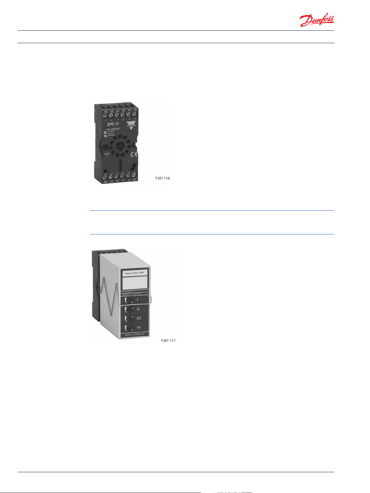
Mounting base and accessories - EHB
General
Mounting base, 11-pole, for EH modules - EHB
EHB can be mounted using two screws. It can also be clipped onto DIN rails (DIN 46277).
EHB is designed to be wired and contains self-lifting terminals and cross/slotted screws.
On all electrical diagrams with EH modules the terminal connections are located in relation to EHB. If
another mounting base is used, the terminal connections can be re-allocated, but the terminal numbers
will remain the same.
Retaining clip on EH module
Retaining clip in spring steel for additionally securing EH modules on EHB where strong vibrations occur.
The code number covers 10 off retaining clips.
6 520L0804 • Rev 0103 • January 2016
Page 7
Technical Information EH Modules
Mounting base and accessories - EHB
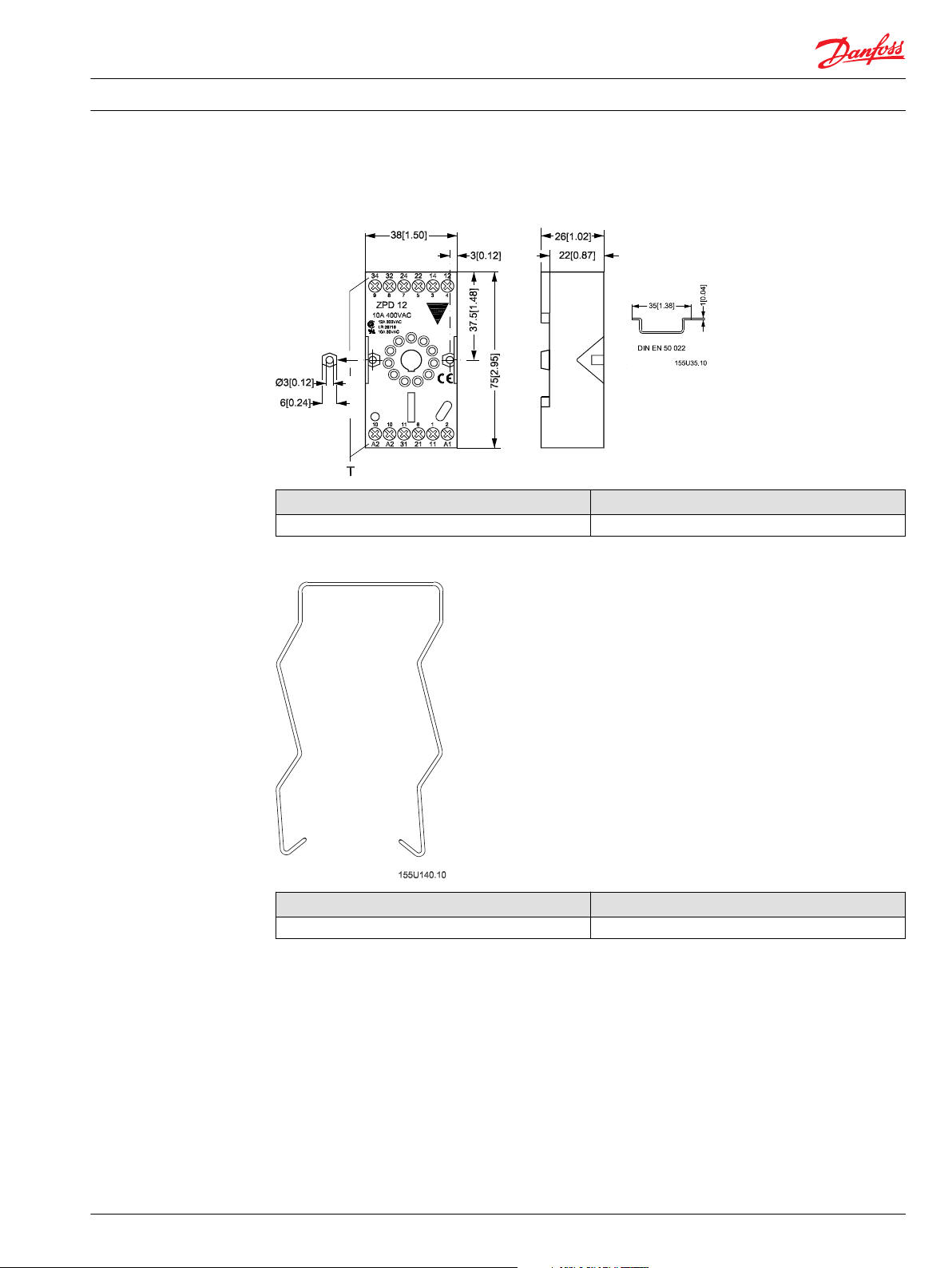
Dimensions, code numbers, and weight
EHB dimensions in millimeters [inches]
EHB mounting base code number EHB base weight
155U0933 0.065 kg (0.143 lb)
EH module retaining clip
EH module retaining clip code number Quantity
155U0932 10
520L0804 • Rev 0103 • January 2016 7
Page 8
Technical Information
EH Modules
Electronic flow regulation - EHF
General
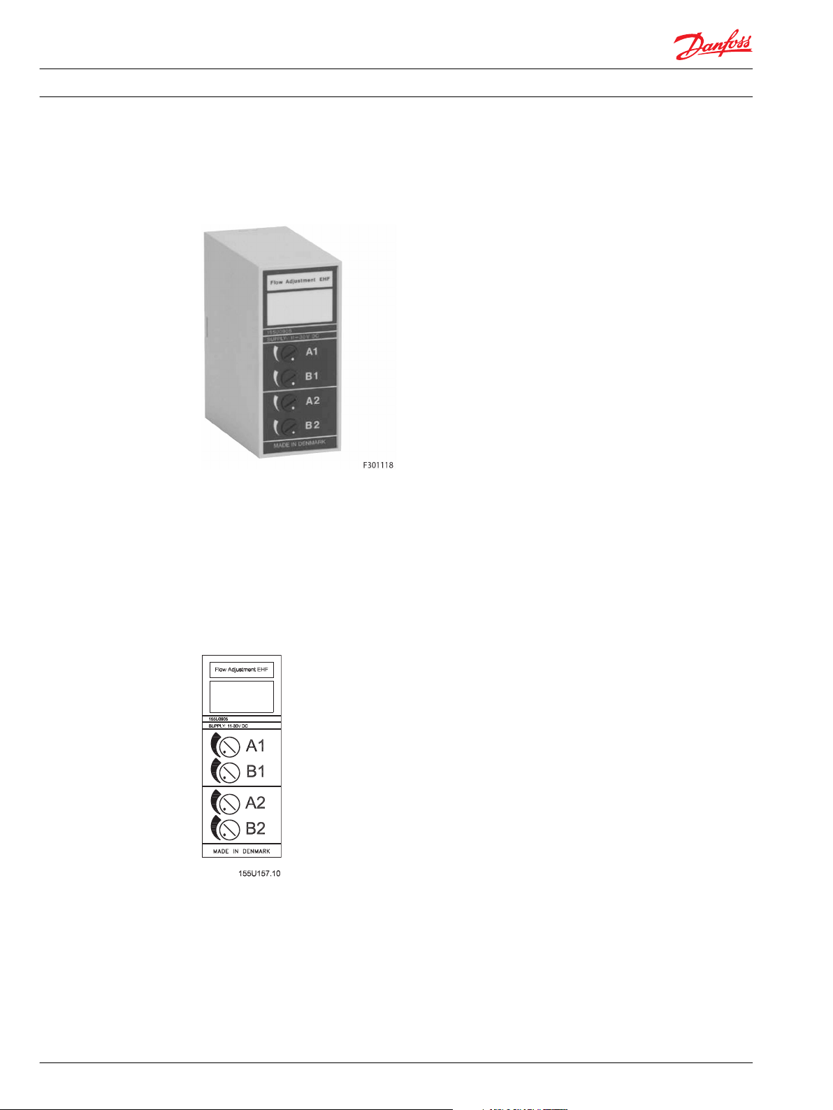
Electronic flow regulation - EHF
Function
Danfoss electronic flow regulation EHF is for use where the requirement is individual reduction of the
flow from the two ports of the proportional valve.
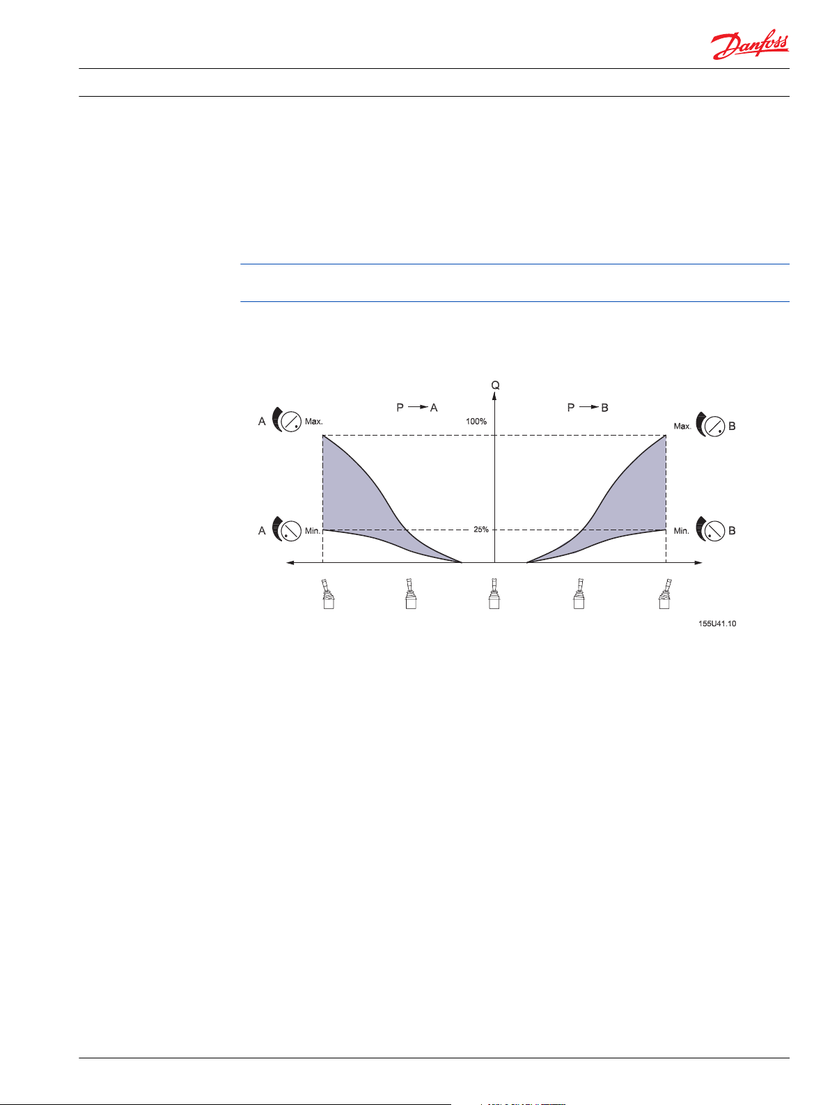
The flow can be reduced individually for ports A and B, infinitely down to 25% of maximum flow.
An EHF built into an electrohydraulic system gives very precise control of the working functions.
EHF is supplied for the regulation of two working functions.
Flow adjustment - EHF
EHF must be inserted in the signal connection between the electric remote control lever and PVG
proportional valve.
There are two built-in potentiometers per function. Independently of each other, these will limit the
signal voltage and thereby the flow from ports A and B.
The remote control unit retains its full regulation range because EHF incorporates dead-band
compensation and reduced signal voltage instead of mechanical reduction of the regulation range of the
remote control unit.
8 520L0804 • Rev 0103 • January 2016
Page 9
Technical Information EH Modules
Electronic flow regulation - EHF
Signal monitoring
EHF has signal monitoring on the signal inputs (terminals 3 and 4). This means that input signals must lie
within the range 0.15 • UDC to 0.85 • UDC.
If the signal is outside the stated range, such as a consequence of short-circuiting to plus or minus supply,
the signal monitoring cuts off the output signal to the proportional valve which then immediately sets
the main spool into neutral position.
If monitoring has cut off the output signal, EHF can only begin functioning again when the supply
voltage has been cut off.
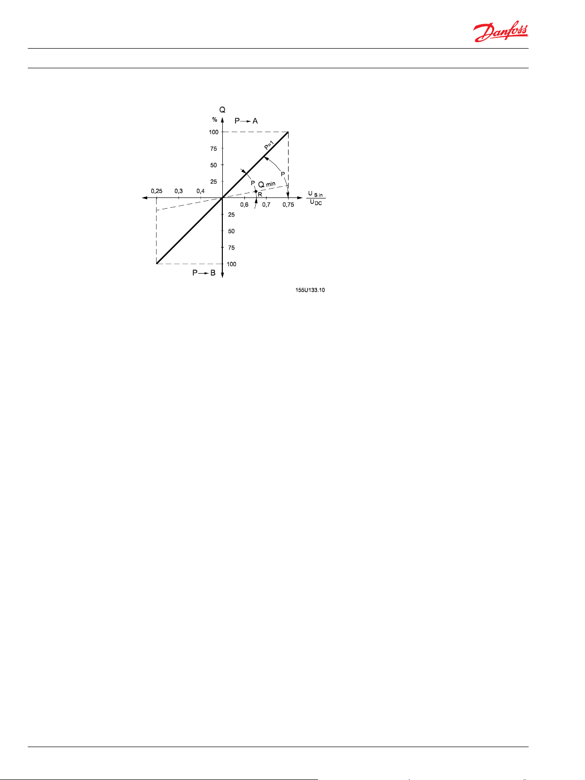
Characteristic
Flow as a function of the input signal and the two potentiometers for the flow limitation at ports A and B
520L0804 • Rev 0103 • January 2016 9
Page 10
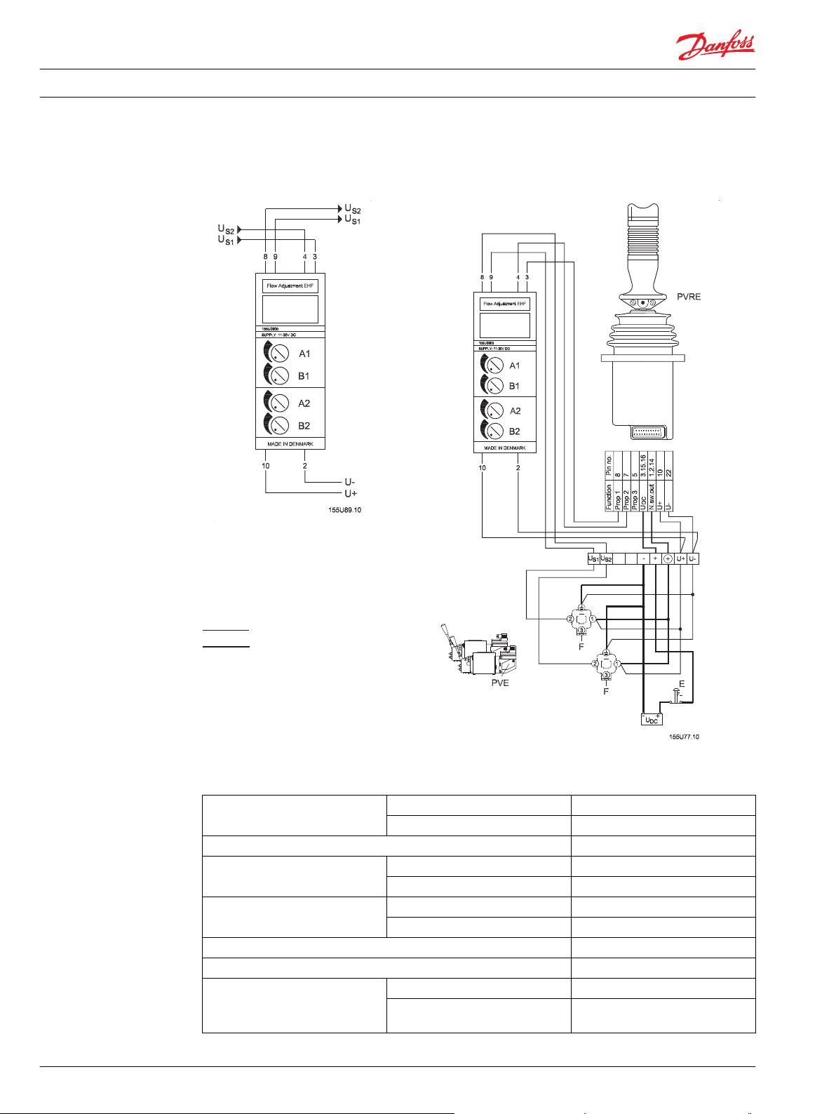
Signal leads
Supply leads
Technical Information EH Modules
Electronic flow regulation - EHF
Electrical system
EHF - electrical system
Technical data
Supply voltage U
Current consumption < 50 mA
Output voltage (US) U
Neutral voltage (US) U
Input signal Remote control lever, potentiometer
Input impedance 12 kΩ at 0.5 • UDC
Output signal Maximum load Two parallelconnected PVEs
10 520L0804 • Rev 0103 • January 2016
DC
11 to 30 V
Maximum ripple 5%
S
U
DC
S
U
DC
Minimum load impedance to 0.5 •
U
DC
0.25 → 0.75
0.5
6 kΩ
Page 11

Technical Information EH Modules
Electronic flow regulation - EHF
Signal current maximum UDC = 12 V ±0.5 mA
Ambient temperature -30 to +60°C [-22 to 140 °F]
Enclosure to IEC 529 IP 42
EHF must be connected to the supply voltage at the same point as the remote control lever.
Code number and weight
EHF mounting base code number EHF base weight
905 0.10 kg (0.22 lb)
UDC = 24 V ±1.0 mA
520L0804 • Rev 0103 • January 2016 11
Page 12
Technical Information
Electronic alarm logic - EHA
General
EH Modules
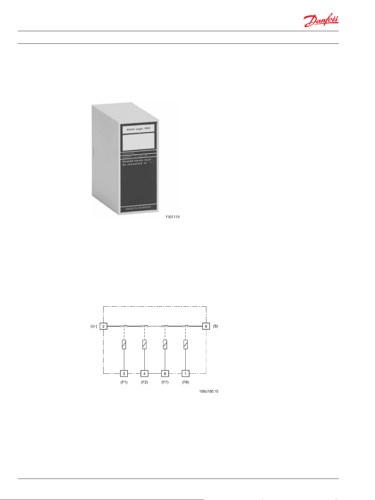
Electronic alarm logic - EHA
Danfoss EHA electronic alarm logic modules are used primarily where together with PVEH electric
activation modules they must meet requirements for optimum system safety.
In principle, EHA can be compared with eight series-connected relays that collect alarm signals from up
to eight PVEH activation modules and via the series connection combine them into a single active output
signal.
The output signal is able to control electric PVPX and PVPE relief valves, normally open (NO) version
which will relieve the LS signal/pump pressure to tank on fault signal from PVEH. These relief functions
make the PVG valves hydraulically inactive.
Alternatively, EHA can be used to control sirens, warning lamps and other alarm sources to indicate
function fault.
12 520L0804 • Rev 0103 • January 2016
Page 13
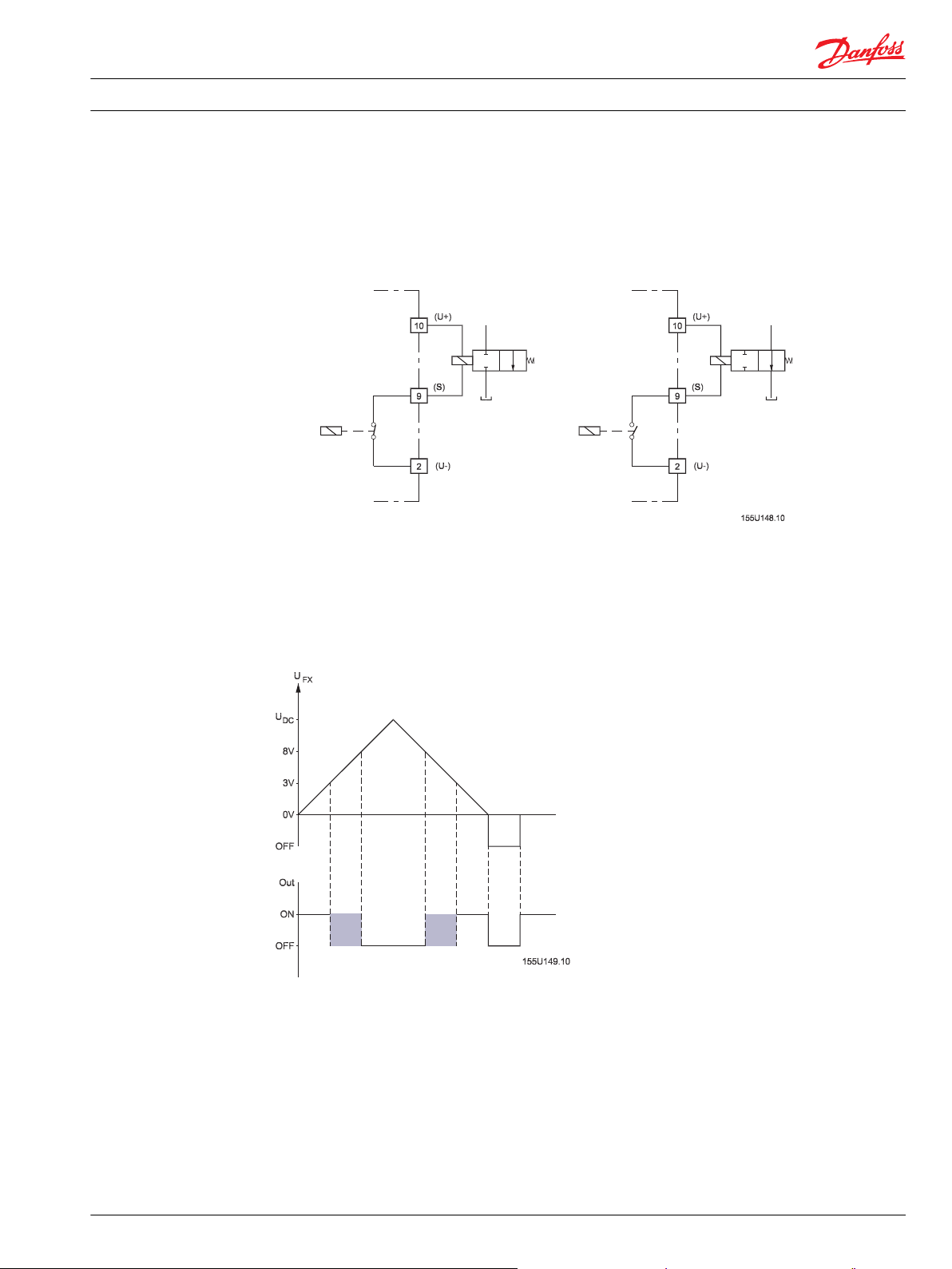
Fault-free function Fault function
Technical Information
Electronic alarm logic - EHA
Function
EH Modules
The alarm outputs from the electrically activated PVEHs in a valve group must be connected to EHA.
EHA is built up so that it is able to monitor up to eight PVEH alarm outputs.
With fault-free function, the EHA output signal is internally connected to minus
If one or more of the PVEH alarms indicate a fault, the EHA output signal is cut off immediately.
To ensure correct function, all unused inputs must be connected to minus, i.e. EHA regards all inputs
without connection as a fault. In addition, all input signals exceeding 8 V are also regarded as faults while
signals of less than 3 V are regarded as fault-free.
In the range 3-8 V the condition remains undefined.
EHA automatically resets when the fault condition no longer exists.
520L0804 • Rev 0103 • January 2016 13
Page 14
DC
U+
Prop 2
Function
Prop 1
Prop 3
N.sw.out
U-
16211
10
PVPX
2
-
3
1
+
1
2
3
U
-
DC
+
E
F3
F2F1
US1UU
S2 S3
- +
U
U-U++
Alarm Logic EHA
be connected to "-".
Unused inputs must
SUPPLY: 11-30V DC
MADE IN DENMARK
155U1805
8 95743
Pin no.
873,15,1651,2,141022
V310176.A
1
2
3
3
1
2
*1
*1
*2
PVEH
PVEH
PVEH
Technical Information EH Modules
Electronic alarm logic - EHA
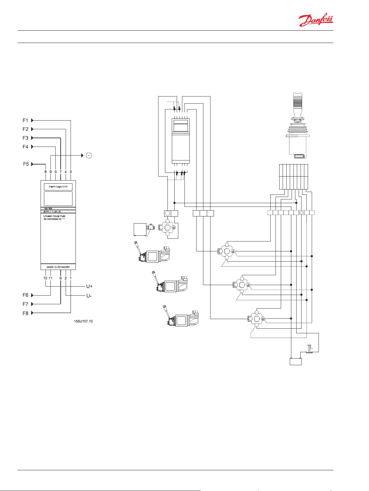
Electrical system
Electronic alarm logic EHA electrical system
1 To avoid being regarded as a fault, unused inputs must be connected to minus.
E Emergency stop
14 520L0804 • Rev 0103 • January 2016
Page 15
Technical Information EH Modules
Electronic alarm logic - EHA
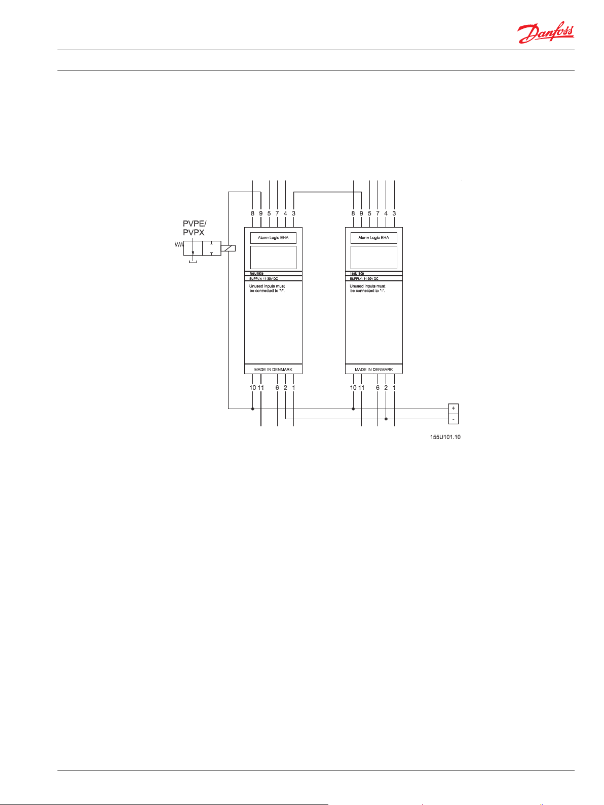
Monitoring more than eight functions
With standard connections, EHA will monitor up to eight alarm outputs.
If more outputs are to be monitored, two or more EHAs can be connected in series by allowing the
output from one EHA to control an input on the following EHA. This extends the capacity by seven inputs
for every extra EHA.
520L0804 • Rev 0103 • January 2016 15
Page 16
Technical Information EH Modules
Electronic alarm logic - EHA
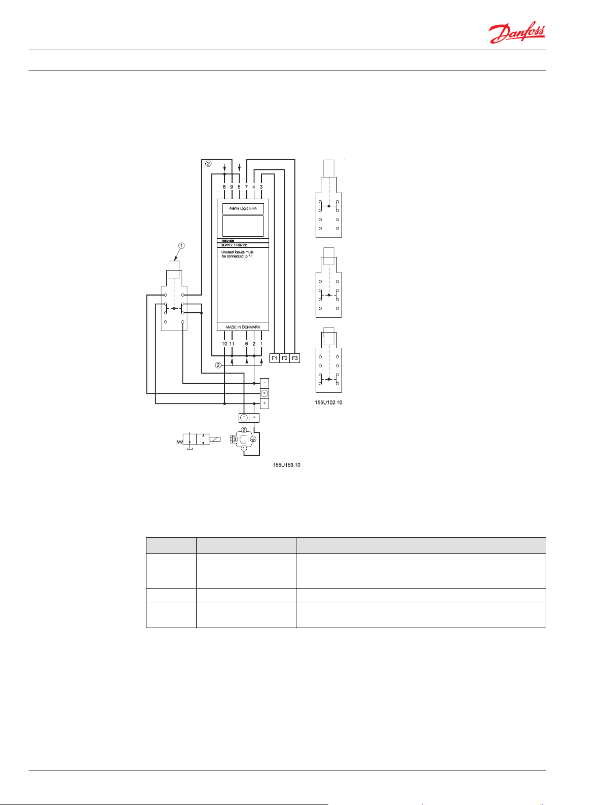
Electric remote to mechanical operation
Changeover between electric remote operation and mechanical operation
1 Switch
2 Unused inputs must be connected to minus
Positions
Position Description Comment
1 Electrical system operation
2 Off
3 Mechanical system
operation
The hydraulics can only be operated by electrical remote control.
The PVEs lock main spools hydraulically and prevent mechanical
operation.
The hydraulics cannot be operated either mechanically or electrically.
The hydraulics can only be operated mechanically.
The relief valve is activated only via the switch.
16 520L0804 • Rev 0103 • January 2016
Page 17

Technical Information EH Modules
Electronic alarm logic - EHA
Technical data
Code number and weight
Supply voltage U
Current consumtion without output load < 40 mA
Input signal Tapping from PVEH fault
Input impedance >3 kΩ
Output load 30 V / 1.5 A
Ambient temperature -30 to + 60°C [-22 to 140 °F]
Enclosure to IEC 529 IP 42
DC
Maximum ripple 5%
Fault-free signal 0 to 3 V
Fault signal 8 V - UDC/Off
11 to 30 V
monitoring
EHA must be connected to supply voltage at the same point as PVEH.
EHA mounting base code number EHA base weight
155U1805 0.09 kg (0.20 lb)
520L0804 • Rev 0103 • January 2016 17
Page 18

Technical Information
EH Modules
Electronic ramp generator - EHR
General
Electronic ramp generator - EHR
Danfoss electronic ramp generator EHR controls the acceleration and deceleration times for flow from
proportional valve ports A and B.
The acceleration and deceleration control is individual for Ports A and B. This form of control is called
ramping of, positive and negative respectively. As standard, ramp times can be controlled from 0-2.5 s,
but can be extended up to 20 s.
When used in an electrohydraulic system, EHR gives "soft" start and stop of the working function.
Function
Setting ramp times - EHR
EHR is inserted in the signal connection between the electric remote control lever and the activation
module in the proportional valve.
EHR damps rapid signal changes while signals that are changed more slowly than the set ramp times are
not changed.
EHR contains four potentiometers for the setting of ramp times. The setting of positive ramps, are made
with A+ and B+ potentiometers for A and B ports respectively, while negative ramps, are set with A− and
B− potentiometers.
There are two different ways of building in EHR:
18 520L0804 • Rev 0103 • January 2016
Page 19

Technical Information EH Modules
Electronic ramp generator - EHR
Principle 1 : Positive and negative ramps
•
Principle 2 : Primarily positive ramps.
•
These two principles are described in more detail in Electrical system - Principle 1 on page 20 and
Electrical system - Principle 2 on page 21.
Signal monitoring
EHR incorporates signal input monitoring, terminal 3. This means that the input signal must lie within the
limits 0.15 • UDC to 0.85 • U
If these limits are exceeded, such as a consequence of short-circuiting to plus or minus supply voltage,
the signal monitoring cuts off the output signal to the proportional valve which as a result immediately
neutral positions the main spool.
If the signal monitoring has cut off the output signal, EHR will only function again after the voltage supply
to it has been cut off.
DC
520L0804 • Rev 0103 • January 2016 19
Page 20

Signal leads
Supply leads
Technical Information
EH Modules
Electronic ramp generator - EHR
Electrical system - Principle 1
EHR electrical system - Principle 1
With the electrical system - Principle 1, it is possible to obtain positive/negative ramps for all input signal
changes.
A signal change over neutral means that the negative ramp is complete before the positive ramp begins.
Terminals 1 and 10 are short-circuited. The neutral position switch (N) is not used. If the external break
contacts (see External break contacts on page 23) are not used, terminals 6 and 11 must be shortcircuited to terminal 10.
20 520L0804 • Rev 0103 • January 2016
Page 21

Signal leads
Supply leads
Technical Information
EH Modules
Electronic ramp generator - EHR
Electrical system - Principle 2
The following system will give mainly positive ramps.
EHR electrical system - Principle 2
An input signal that goes to or passes neutral will prevent a negative ramp. Negative ramps can be
obtained in two ways:
•
On signal changes that do not go completely to neutral.
•
With use of external break contacts (see External break contacts on page 23).
To fulfill principle 2, terminal 1 and 10 must not be short-circuited. If the external break contacts are not
used, terminals 6 and 11 must be short-circuited to terminal 10.
520L0804 • Rev 0103 • January 2016 21
Page 22

C = t-2.5
0.7
[µF]
Technical Information
EH Modules
Electronic ramp generator - EHR
Ramp times
As standard, ramp times can be set between 0 and 2.5 s for 0 to max. flow.
Ramp times can be increased by inserting a bipolar capacitor externally between terminals 8 and 5.
Ramp times are dependent on the size of the capacitor, which can be calculated using the following
formula for t > 2.5 s:
t is the required ramp time in seconds. The ramp time must not exceed 20 seconds.
To ensure that the capacitor (C) functions as intended, it must have very low leakage current (see
specification in Technical data on page 10).
22 520L0804 • Rev 0103 • January 2016
Page 23

Technical Information
EH Modules
Electronic ramp generator - EHR
External break contacts
KA, KB signals
Negative ramps can be obtained with break contacts KA/KB, both in principle 1 and 2.
When KA or KB breaks, a negative ramp is generated for ports A and B respectively. A contact in break
position prevents further signals in the same direction. KA and KB are therefore suitable as limit switches,
such as for slewing movement on a crane.
When the voltage on KA/KB is less than 3 V or OFF, the KA/KB function is regarded as OFF and a negative
ramp is generated.
When the voltage on KA/KB is greater than 8 V, the KA/KB function is regarded as ON.
In the range between 3 and 8 V, the KA/KB function remains undefined.
520L0804 • Rev 0103 • January 2016 23
Page 24

Technical Information EH Modules
Electronic ramp generator - EHR
Technical data
Supply voltage U
DC
11 to 30 V
Max. ripple 5%
Current consumption < 50 mA
Output voltage (US) U
Neutral voltage (US) U
S
U
DC
S
U
DC
0.25 → 0.75
0.5
Input signal Remote control lever, potentiometer
Input impedance t3 12 kΩ to 0.5 • U
DC
t1/6/11 > 5Ω
Output signal Maximum load Two parallel connected PVEs
Minimum load impedance to 0.5 •
M6 kΩ
UDC
Signal current UDC = 12 V ± 0.5 mA
UDC = 24 V ± 1.0 mA
Settings Positive ramp port A A+
Negative ramp port A A-
Positive ramp port B B+
Negative ramp port B BExternal cutoff switches KA breaks ramp A -
KB breaks ramp B -
KA/KB OFF < 3 V/OFF
KA/KB ON 8 V → UDC
Ramp times (0 to max. flow) Standard 0 → 2.5 s.
With external capacitor (C) 0 → 20 s.
Ambient temperature -30 to + 60 °C [-22 to 140 °F]
Enclosure to IEC 529 IP 42
External capacitor (C) Operating voltage Minimum 10V
Insulation resistance Minimum 5 GΩ
Time constant, RC Minimum 5000 s.
EHR ramp generator must be connected to supply voltage at the same point as the remote control lever.
Code number and weight
EHR mounting base code number EHR base weight
155U2905 0.12 kg (0.26 lb)
24 520L0804 • Rev 0103 • January 2016
Page 25

Technical Information
EH Modules
Electronic speed control - EHS
General
Electronic speed control - EHS
The Danfoss electronic speed control EHS takes up an electric pulse signal related to rotational
movement. e.g. the speed of a shaft, the speed of a vehicle.
The pulse signal is converted into a proportional signal that is applied, via port A on the proportional
valve, to control the speed of a hydraulic motor.
EHS also gives the possibility of infinite flow regulation.
In other words, EHS and PVG together create a variable electrohydraulic gear.
Function
EHS controls the flow from the proportional valve, in relation to the frequency of the electric signal from a
tachometer pulse source.
EHS contains two potentiometers, used to set the frequency necessary to give maximum movement of
the proportional valve and compensate for leakage in the hydraulic system itself.
An externally connected potentiometer allows the infinite regulation of the ratio between frequency and
flow.
When a frequency is applied to EHS, the proportional valve immediately functions to give the
corresponding flow.
520L0804 • Rev 0103 • January 2016 25
Page 26

Technical Information
EH Modules
Electronic speed control - EHS
To ensure linearity between frequency and flow, EHS compensates for the progressive flow characteristic
of the proportional valve.
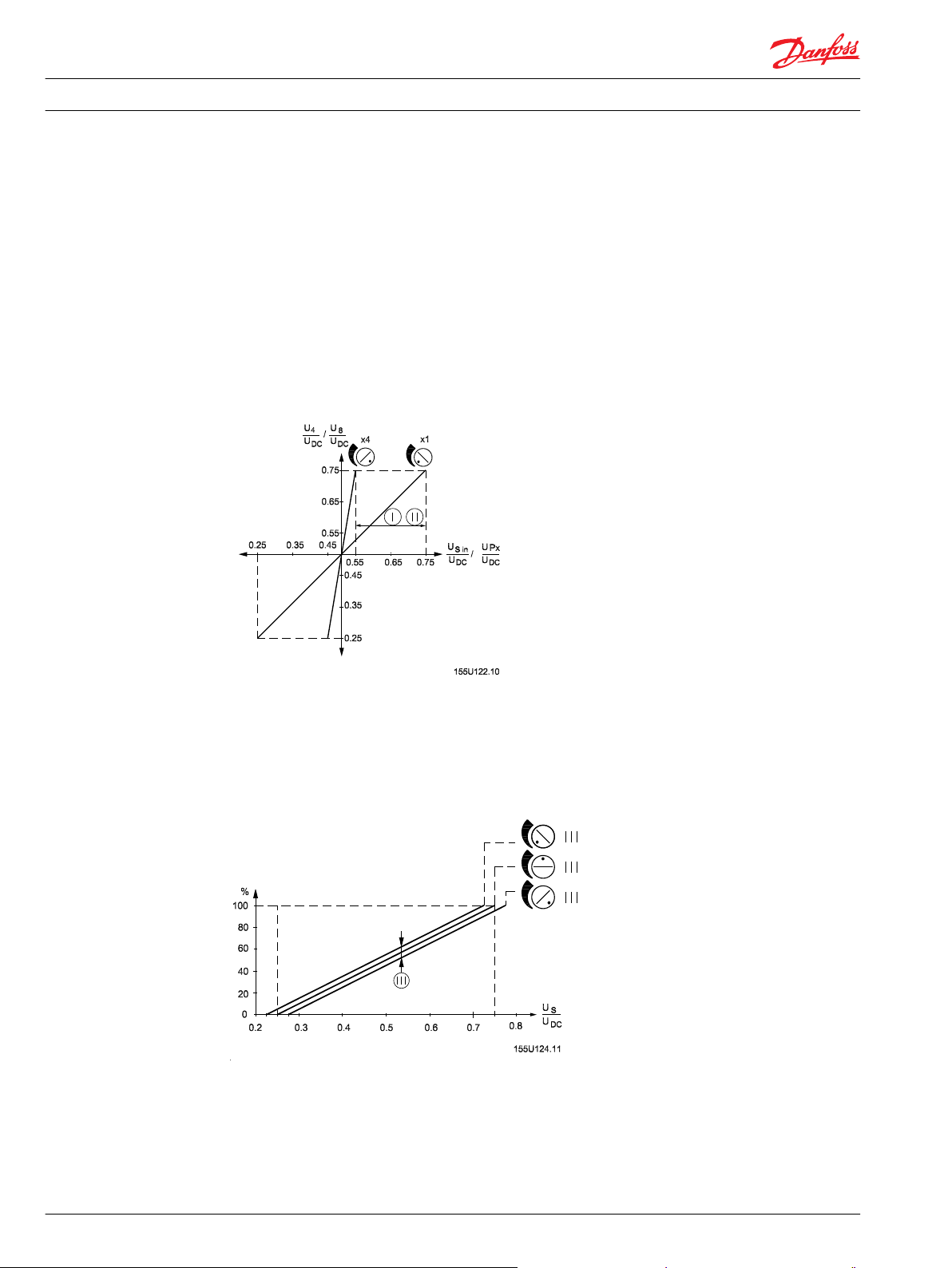
Potentiometer 1
Potentiometer 1 - Adjustment of f
max
Potentiometer 2
Potentiometer 1 determines the frequency, f
the proportional valve 50 Hz < f
< 200 Hz
max
, i.e. the frequency that must give maximum flow from
max
Q0 is the least flow supplied from the proportional valve. The adjustment of potentiometer 2
compensates both for the dead band of the proportional valve and leakage in the hydraulic system.
Q0 becomes effective at not more than 3% of f
max
.
If 100 % (maximum flow) is exceeded, potentiometer Px (see Potentiometer (P) on page 27) is inserted to
eliminate the excess in order to obtain optimum utilization of the regulation range. If Px is not used,
either Q0 (potentiometer 2) or f
(potentiometer 1) must be adjusted down.
max
26 520L0804 • Rev 0103 • January 2016
Page 27

P
R =
__________________
[Ω]
Q
max
__________
− 1
Q
min
Technical Information
EH Modules
Electronic speed control - EHS
Potentiometer (P)
Recommendation
Potentiometer (P) regulates the amplification in EHS and thereby the ratio between frequency and flow.
The resistor (R) increases Q
R can be calculated with f
over Q0. R must always be inserted as at least 5% of P.
min
as:
max
5Ω < (R + P ( + Px)) < 22 kΩ
R + P : Recommendation 10 kΩ
To ensure reliable regulation of the hydraulic system, the ratio between amplitude and pulse pause (X:Y)
for the pulse signal must be maintained (see Technical data on page 29).
It is recommended that EHS be used with electric activation module PVEH in every case.
Input reference
In some cases the pulse source is unable to fulfill the requirement that amplitude must be ± 1 V in
relation to the reference 0,5 • UDC.
520L0804 • Rev 0103 • January 2016 27
Page 28

Technical Information EH Modules
Electronic speed control - EHS
In these cases it is possible to reduce the reference level by using an external potentiometer between
terminals (10) and (2) with input to terminal (1). The reference will then be the same as the voltage level
on terminal (1).
28 520L0804 • Rev 0103 • January 2016
Page 29

Signal leads
Supply leads
Technical Information EH Modules
Electronic speed control - EHS
Electrical connection
Technical data
Supply voltage U
DC
11 to 30 V
Maximum ripple 5%
Current consumption < 35 mA
Output voltage (US) U
Neutral voltage (US) U
S
U
DC
S
U
DC
0.5 → 0.25
0.5
Input signal Pulse source
Minimum amplitude 0.5 • UDC ± 1 V
Pulse - pause ratio (x : y) 1 : 1 ± 10%
Maximum flow frequency 50 - 200 Hz
Input impedance to 0.5 • UDC 56 Ω
520L0804 • Rev 0103 • January 2016 29
Page 30

Technical Information EH Modules
Electronic speed control - EHS
Output signal Maximum load Two parallel connected PVEs
Signal current maximum UDC = 12 V 0 → - 0.5 mA
Resistance (terminals (4) to (8)) R + P (+Px) 5 → 22 kΩ
Terminal (5) Impedance to 0.5 • U
Terminal (1) Impedance to 0.5 • U
Ambient temperature -30 to + 60 °C [-22 to 140 °F]
Enclosure to IEC 529 IP 42
EHS must be connected to supply voltage at the same point as PVE.
Code number and weight
Minimum load impedance to 0.5 •
UDC
Flow P → A
Error in % of US maximum < 5
UDC = 24 V 0 → - 1.0 mA
Recommended 10 kΩ
DC
DC
6 kΩ
1 MΩ
> 56 kΩ
EHS mounting base code number EHS base weight
155U3905 0.10 kg (0.22 lb)
30 520L0804 • Rev 0103 • January 2016
Page 31

Technical Information
EH Modules
Electronic, frequency controlled loop speed control - EHSC
General
Electronic, Frequency Controlled Loop Speed Control - EHSC
Danfoss electronic, frequency controlled speed control EHSC is used in closed loop control systems. It
controls the oil flow from the proportional valve A port and thus the speed of a hydraulic motor.
The speed is adjusted to correspond to a control frequency (speed signal) from, for example, a speed
encoder on the wheelaxle of a vehicle. A second speed encoder fitted on the hydraulic motor shaft
provides a feedback frequency.
EHSC compares the control and the feedback frequency, and the oil flow is adjusted so the ratio between
the two signals is correct. In this way the speed of the hydraulic motor corresponds to the speed of the
vehicle.
When the vehicle changes speed, the speed of the hydraulic motor will be changed accordingly. This
means, for example, that a gritter will distribute a constant quantity of sand over every m2 road surface regardless of the speed of the vehicle and the load on the hydraulic motor.
Adjustment possibilities
In EHSC there are four built-in potentiometers which are adjusted in order to achieve optimum speed
control.
520L0804 • Rev 0103 • January 2016 31
Page 32

Technical Information
EH Modules
Electronic, frequency controlled loop speed control - EHSC
By adjusting potentiometer 1, proportional valve dead band and internal leakage of the hydraulic
•
system are compensated.
With potentiometer 2 the working range of the EHSC is set and thereby the control frequency that
•
gives maximum oil flow from the proportional valve.
With potentiometer 3 the feedback frequency is set corresponding to maximum motor speed at
•
maximum oil flow from the proportional valve.
With potentiometer 4 possible tendencies to system hunting are eliminated.
•
With an external potentiometer the relationship between control frequency and oil flow can be adjusted
in the range from 0 to 2. This means that maximum oil flow from the proportional valve is possible even
at 50% of the set maximum control frequency, just as it is possible to shut off oil flow irrespective of
control frequency.
Function monitoring
EHSC has an INFO output controlled by a function monitor. A warning lamp can be connected to the
INFO output.
Constantly lit lamp means that EHSC is functioning correctly.
•
Flashing lamp means that the difference between the control and the feedback frequencies is too big
•
for the EHSC to correct.
Unlit lamp means that either the control or the feedback frequency has been interrupted.
•
If the feedback frequency has been interrupted, EHSC switches automatically to open loop speed control.
This means it will still control the oil flow from the proportional valve, but only in relation to the control
frequency.
Adjustments
Potentiometer 1
Q0 is the least oil flow supplied from the proportional valve at a stable control frequency (3% of f
32 520L0804 • Rev 0103 • January 2016
fmax
).
Page 33

Technical Information
EH Modules
Electronic, frequency controlled loop speed control - EHSC
Adjustment of minimum oil flow (Q0)
Potentiometer 2
Adjustment of maximum feed back frequency (f
): 50 Hz < f
fmax
fmax
< 300 Hz
The setting of potentiometer 2 determines the control frequency giving maximum oil flow (Q
the proportional valve. If f
If Q
is exceeded, potentiometer Px can be inserted to obtain optimal use of the control range. If Px is
100
not used, either Q0 or f
is set correctly, the test signal terminal 4 (U4) will be 5.25 V.
fmax
should be reduced. (See Potentiometer 1 on page 32 and Potentiometer 2 on
fmax
100
) from
page 33).
520L0804 • Rev 0103 • January 2016 33
Page 34

fb [Hz]
U6
[V] = • 1,75 [V] + 3,5 [V]
f
b max
[Hz]
Q l/min [US gal/min]
• ppr • 1000
motor displacement [cm3]
fb [Hz] =
60
Technical Information EH Modules
Electronic, frequency controlled loop speed control - EHSC
Potentiometer 3
Adjustment of maximum feed back frequency (f
The setting of potentiometer 3 determines the maximum feedback frequency corresponding to
maximum speed for the hydraulic motor at maximum oil flow.
When ordering EHSC there is a choice of two ranges for feedback frequency:
800 Hz < f
•
b max
< 8000 Hz
b max
)
or
30 Hz < f
•
If f
is set correctly, the test signal terminal 6 (U6), will be 5.25 V.
b max
b max
< 300 Hz
If the system utilizes the maximum flow capacity of the main spool, the test signal on terminal 6 (U6) must
be 5.25 V at f
b max
.
If the system does not utilize the maximum flow capacity of the main spool, the setting of U6 must be
calculated as follows:
fb is the actual maximum system feedback frequency. fb maximum is the feedback frequency on
maximum movement of the main spool.
Both fb and f
can be calculated thus:
b max
In calculating fb, Q is inserted as the actual maximum system flow. At fb maximum, Q is inserted as the
maximum flow capacity of the main spool.
Example:
Main spool Motor
PVG 32 OMS 80 EM
157B9764 151F3000
34 520L0804 • Rev 0103 • January 2016
Page 35

65 l/min [17.17 US gal/min]
• 15 • 1000
80 cm
3
fb [Hz] =
60
= 203 Hz
100 l/min [26.42 US gal/min]
• 15 • 1000
80 [cm3]
f
b max
[Hz] =
60
= 313 Hz
[V] = 203 Hz
• 1.75 [V] + 3.5 [V]
313 Hz
U
6
Technical Information
EH Modules
Electronic, frequency controlled loop speed control - EHSC
Example: (continued)
Main spool Motor
100 l/min
[26.42 US gal/min]
(4/3-open) (ppr = 15)
80 cm
3
Potentiometer (P)
Potentiometer 4
Potentiometer 4 is used to set the integration time in the EHSC integrator stage. The integrator stage
equalises the difference between forward and feedback frequencies. The integration time can be set
between 50 and 300 ms.
A short integration time means fast correction of speed deviations.
The permissible integration time is systemdependent. Too short an integration time can produce hunting
in the system.
520L0804 • Rev 0103 • January 2016 35
Page 36

Technical Information
EH Modules
Electronic, frequency controlled loop speed control - EHSC
The external potentiometer (P) determines the relationship between the control frequency and the oil
flow.
The ratio is infinitely variable in the range from 0 to 2.
Max. oil flow is achieved from 0.5 ↔ ff max at P = 2.
The oil flow may be cut off in the entire control range at P = 0.
Recommended value for potentiometer resistance P: 10 kΩ
Range for potentiometer resistance
P: 5 kΩ < P < 20 kΩ
Resistance (R)
The resistance (R) is only inserted if the oil flow must not be cut off completely. R forms a lower limit for
the control frequencey and oil flow (Qmin) ratio.
Recommended value for the total resistance P + R = 10 kΩ
Range for the total resistance P + R: 5 kΩ < P + R < 20 kΩ
36 520L0804 • Rev 0103 • January 2016
Page 37

Signal leads
Supply leads
Technical Information EH Modules
Electronic, frequency controlled loop speed control - EHSC
Electrical system
Technical data
E Emergency stop
F Signal output, fault monitoring
Supply voltage
Current consumption < 100 mA
Control frequency
Control frequency test, value at maximum control frequency (terminal 4) 5.25 V
Signal voltage (US) 0.50 → 0.25 • U
Neutral position voltage (ff = 0 Hz) 0.50 • U
520L0804 • Rev 0103 • January 2016 37
*
U
DC
11 to 30 V
Maximum ripple 5%
†
Minimum amplitude 3.5 V ± 1 V
Pulse-pause-ratio 1 : 1 ± 10%
Frequency at maximum flow 50 - 300 HZ
Input impedance >30 kΩ
DC
DC
Page 38

Technical Information EH Modules
Electronic, frequency controlled loop speed control - EHSC
Feedback frequency
†
Minimum amplitude 3.5 V ± 1 V
Pulse-pause-ratio 1 : 1 ± 10%
Frequency at maximum flow 800 → 8000 Hz
30 → 300 Hz
Input impedance > 30 kΩ
Feedback frequency test, value at maximum frequency (terminal 6) 5.25 V
Output signal Maximum load Two parallel connected PVE
Minimum load impedance to 0.5 •
U
DC
6 kΩ
Error in relation to maximum flow < 1%
Oil flow direction US = 0.50 → 0.75 • U
US = 0.50 → 0.25 • U
DC
DC
P → A
P → B
Signal current UDC = 12 V 0 → -0.5 mA
UDC = 24 V 0 → -1.0 mA
Load between terminals 4 and 8 P or (P + R) 5 → 20 kΩ
Recommended 10 kΩ
Input impedance (terminal 5) > 1 MΩ
Info output (terminal 11) Maximum load -100 mA
Ambient temperature - 30 → + 60°C [-22 to 140 °F]
Enclosure to IEC 529 IP 42
*
EHSC must be connected to the voltage supply in the same place as PVE.
†
See Required control and feedback frequency signal on page 38.
Required control and feedback frequency signal
To ensure reliable control of the hydraulic system, it is necessary to comply with the amplitude and pulse/
pause ratio (X : Y) stated for the control and feedback frequencies (see Technical data on page 37).
Main spools and electrical actuation modules
Danfoss recommends the use of a PVBS main spool with linear characteristic and a PVES electrical
actuation module.
Code number and weight
EHSC mounting base code number EHSC base weight EHSC feedback frequency
155U3815 0.14 kg (0.31 lb) 30 → 300 Hz
38 520L0804 • Rev 0103 • January 2016
Page 39

Technical Information
EH Modules
Electronic, voltage controlled closed loop speed control - EHSC
General
Electronic, Voltage Controlled Closed Loop Speed Control - EHSC
Danfoss electronic, voltage controlled speed control EHSC is used in closed loop control systems. It
controls the oil flow from the A and B ports of the proportional valve and consequently the speed of a
hydraulic motor.
The speed is controlled so that it corresponds to an analogue voltage signal from e.g. a remote control
lever. A speed encoder connected to the hydraulic motor shaft provides a feedback frequency.
EHSC compares the control signal with the feedback frequency and controls, via a PVG proportional
valve, the oil flow so that the feedback frequency corresponds to the control signal. The speed of the
hydraulic motor will then correspond to the move-ment of the remote control lever regard-less of the
load on the hydraulic motor.
Adjustment possibilities
In the EHSC four built-in potentiometers are used for the adjustment, to achieve optimum speed control:
Adjusting potentiometers 1 and 2 compensates for proportional valve dead band in directions A and
•
B plus the internal leakage of the hydraulic system.
Potentiometer 3 sets the max. feedback frequency corresponding to the max. speed of the motor at
•
max. oil flow from the proportional valve.
With potentiometer 4 possible tendencies of system hunting are eliminated.
•
520L0804 • Rev 0103 • January 2016 39
Page 40

Technical Information
EH Modules
Electronic, voltage controlled closed loop speed control - EHSC
With an external potentiometer the relationship between control signal and oil flow can be infinitely
varied in the 0 to 1 range. A reduction of the control signal and oil flow ratio applies to both the A and the
B port.
Function monitoring
EHSC has an INFO-output controlled by a function monitor. A warning lamp can be connected to the
INFO output.
Constantly lit lamp means that EHSC is functioning correctly
•
Flashing lamp means that the deviation between the control signal and feedback frequency is too big
•
for EHSC to correct.
No light means that the control signal or the feedback frequency has been cut off.
•
The INFO-output cannot be damaged by a short circuit.
If the feedback frequency is cut off, EHSC switches automatically to open loop
speed control. This means that EHSC is still controlling the oil flow from the proportional valve, but now
only in relation to the control signal.
The control signal is constantly monitored. If the signal is outside the range 0.15 → 0.85 • UDC, the signal
output to PVE is cut off. This results in the main spool returning to neutral position, and at the same time
the INFO-output light will switch off.
If the function monitor has cut off the signal output, EHSC can only be re-activated after a disconnection
of the supply voltage.
40 520L0804 • Rev 0103 • January 2016
Page 41

Technical Information
EH Modules
Electronic, voltage controlled closed loop speed control - EHSC
Adjustments
Potentiometer 1 and 2
Adjustment of min. oil flow (Q0A), A-port; Adjustment of min. oil flow (Q0B), B-port
DA : Dead band P
→ A
DB : Dead band P → B
Q0 is the smallest oil flow supplied by the proportional valve at a stable control signal.
Potentiometer 3
Adjustment of maximum feed back frequency (f
b max
)
The setting of potentiometer 3 determines the maximum feedback frequency corresponding to
maximum speed for the hydraulic motor at maximum oil flow.
520L0804 • Rev 0103 • January 2016 41
Page 42

fb [Hz]
U6
[V] = • 1,75 [V] + 3,5 [V]
f
b max
[Hz]
Q l/min [US gal/min]
• ppr • 1000
motor displacement [cm3]
fb [Hz] =
60
65 l/min [17.17 US gal/min]
• 15 • 1000
80 cm
3
fb [Hz] =
60
= 203 Hz
100 l/min [26.42 US gal/min]
• 15 • 1000
80 [cm3]
f
b max
[Hz] =
60
= 313 Hz
[V] = 203 Hz
• 1.75 [V] + 3.5 [V]
313 Hz
U
6
Technical Information
EH Modules
Electronic, voltage controlled closed loop speed control - EHSC
When ordering EHSC there is a choice of two ranges for feedback frequency:
800 Hz < f
•
or
30 Hz < f
•
If f
is set correctly, the test signal terminal 6 (U6), will be 5.25 V.
b max
If the system utilizes the maximum flow capacity of the main spool, the test signal on terminal 6 (U6) must
be 5.25 V at f
If the system does not utilize the maximum flow capacity of the main spool, the setting of U6 must be
calculated as follows:
fb is the actual maximum system feedback frequency. fb maximum is the feedback frequency on
maximum movement of the main spool.
Both fb and f
< 8000 Hz
b max
< 300 Hz
b max
.
b max
can be calculated thus:
b max
In calculating fb, Q is inserted as the actual maximum system flow. At fb maximum, Q is inserted as the
maximum flow capacity of the main spool.
Example:
Main spool Motor
PVG 32 OMS 80 EM
157B9764 151F3000
100 l/min
[26.42 US gal/min]
(4/3-open) (ppr = 15)
42 520L0804 • Rev 0103 • January 2016
Potentiometer 4
Potentiometer 4 - Error signal amplification is used to set the amplification of the deviation between the
control signal and the feedback frequency. This amplification means that even small deviations can be
corrected.
80 cm
3
Page 43

Technical Information
EH Modules
Electronic, voltage controlled closed loop speed control - EHSC
The permissible amplification factor depends on the system. An excessively high factor may lead to
system hunting.
Potentiometer (P)
Resistance (R)
The external potentiometer (P) determines the relationship between the control signal and the oil flow.
The ratio is infinitely variable from 0 to 1. The oil flow can be cut off completely within the control range
(at P = 0).
Recommended value for potentiometer resistance P: 10 kΩ
Range for potentiometer resistance: P: 5 kΩ < P < 20 kΩ
The resistance (R) is only inserted if the oil flow must not be cut off.
R marks a lower limit for the control signal and oil flow (Qmin) ratio.
Recommended value for the total resistance P + R = 10 kΩ
Range for the total resistance
P + R: 5 kΩ < P + R < 20 kΩ
520L0804 • Rev 0103 • January 2016 43
Page 44
Technical Information EH Modules
Electronic, voltage controlled closed loop speed control - EHSC
44 520L0804 • Rev 0103 • January 2016
Page 45

Signal leads
Supply leads
Technical Information EH Modules
Electronic, voltage controlled closed loop speed control - EHSC
Electrical system
E Emergency stop
F Signal output, fault monitoring
Technical data
Supply voltage
Current consumption < 100 mA
Signal voltage (US) 0.50 → 0.75 • U
Neutral position signal 0.5 • U
Control signal Remote control lever or
520L0804 • Rev 0103 • January 2016 45
*
U
DC
11 - 30 V
Maximum ripple 5%
DC
DC
potentiometer
Input impedance >30 kΩ
Page 46

Technical Information
EH Modules
Electronic, voltage controlled closed loop speed control - EHSC
Feedback frequency
Feedback frequency test, value at max. frequency (terminal 6) 5.25 V
Output signal Maximum load Two parallel connected PVEs
Oil flow direction US = 0.50 → 0.75 • U
Signal current UDC = 12 V ± 0.5 mA
Load between terminals 4 and 8 P or (P + R) 5 → 20 kΩ
Input impedance (terminal 5) > 1 MΩ
Info output (terminal 11) Maximum load -100 mA
Ambient temperature - 30 → + 60°C [-22 to 140 °F]
Enclosure to IEC 529 IP 42
*
EHSC must be connected to the voltage supply in the same place as PVE.
†
See Required control and feedback frequency signal on page 38.
†
Minimum amplitude 3.5 V ± 1 V
Pulse-pause-ratio 1 : 1 ± 10%
Freqency at maximum flow 800 → 8000 Hz
30 → 300 Hz
Input impedance > 30 kΩ
Minimum load impedance to 0.5 •
U
DC
Error in relation to max. flow < 1%
DC
US = 0.50 → 0.25 • U
UDC = 24 V ± 1.0 mA
Recommended 10 kΩ
DC
6 kΩ
P → A
P → B
Required feedback frequency signal
To ensure reliable control of the hydraulic system it is necessary to comply with the amplitude and pulse/
pause ratio for the feedback frequency (see technical data).
Main spools and electrical actuation modules
Danfoss recommends the use of a PVBS main spool with linear characteristic and a PVES electrical
actuation module.
46 520L0804 • Rev 0103 • January 2016
Page 47

Technical Information EH Modules
Electronic, voltage controlled closed loop speed control - EHSC
Code number and weight
Electronic, voltage controlled closed loop speed control EHSC
Code number
Weight
Feedback
frequency
155U3815
0.14 kg (0.31 lb)
30 → 300 Hz
520L0804 • Rev 0103 • January 2016 47
Page 48

Technical Information
EH Modules
Electronic closed loop position control - EHC
General
Electronic Closed Loop Position Control - EHC
Adjustment possibilities
Danfoss electronic position control EHC is used for the positioning of an actuator in a closed loop control
system. The set-point signal is an analogue voltage signal from e.g. a remote control lever. A position
transducer on the actuator provides the feedback signal (position signal).
EHC compares the set-point signal with the feedback signal and adjusts the oil flow, via the PVG
proportional valve, so that the actuator position corresponds to the set-point signal.
This means that the actuator shaft or piston rod is moved into and kept in the position corresponding to
the controlling movement of the remote control lever.
In EHC there are four built-in potentiometers for the adjustment of EHC, in order to achieve optimum
position control.
Potentiometer 1 - Setting of scale for set point signal.
•
Potentiometer 2 - Setting of scale for feedback signal.
•
The scale settings for the set-point and feedback signals are used for the adjustment of standard
transducers, so their signal range can be fully utilized. The scaling is used when, e.g. a 270° angle
transducer is utilized only in 60° of its turning range.
48 520L0804 • Rev 0103 • January 2016
Page 49

Technical Information
EH Modules
Electronic closed loop position control - EHC
Potentiometers 1 and 2 can be set for between 1 and 4 times amplification of the set-point and feedback
signals respectively. The amplification is made in proportion to half supply voltage (0,5 • UDC ).
Potentiometer 3 - Position adjustment. The position adjustment adds a fixed signal to the set-point
•
signal. The adjustment is used to make sure that the set-point signal and feedback signal correspond
to each other at a certain, critical actuator position. This may be the neutral position, an extreme
position, etc.
Potentiometer 4 - Error signal amplification control. Potentiometer 4 is used to set the amplification
•
of the deviations between the set-point signal and the feedback signal. The amplification means that
even small deviations can be corrected. The amplification factor can be set at between 1 and 100.
Inverse function
With the built-in inverse function the EHC set-point signal can be reversed in relation to 0,5 UDC so that
set-point signals in the 0,5 → 0,75 UDC range are converted to set-point signals in the 0,5 → 0,25
•
UDC range and
set-point signals in the 0,5 → 0,25 UDC range are converted to set-point signals in the 0,5 → 0,75
•
UDC range.
The inverse function is activated by connecting terminals 1 and 10. If terminals 1 and 10 are connected
via a switch, it will be possible to alternate between normal and inverse function.
Interruption of the signal output
The signal output to the proportional valve (US ) can be controlled by placing a make contact between
terminals 6 and 10. If this connection between terminals 6 and 10 is made, the signal to the proportional
valve and the INFO-output are interrupted.
When there is no connection between terminals 6 and 10, the signal output is controlled by the function
monitoring alone.
520L0804 • Rev 0103 • January 2016 49
Page 50

Technical Information
EH Modules
Electronic closed loop position control - EHC
ON/OFF signal t1/t6
The external contact function cannot be used on EHC with no relay in the signal output.
When voltage on t1/t6 is less than 3 V or OFF, the t1/t6 function is regarded as OFF.
When t1/t6 voltage is greater than 8 V, the t1/t6 function is regarded as ON.
In the range 3 to 8 V, t1/t6 remains undefined.
Redundant position transducer
EHC can receive and compare two parallel feedback signals. This gives higher system security.
In case just one of the signals fails, the INFO-output is switched off (and the signal output, terminal 9, if
any). See the section on function monitoring. If only one position transducer is used, it must be
connected to both terminals 5 and 7.
50 520L0804 • Rev 0103 • January 2016
Page 51

Technical Information
EH Modules
Electronic closed loop position control - EHC
Function monitoring
EHC has function monitoring on the set-point and feedback signals. The function monitoring has two
purposes:
1. Via a relay in the signal output terminal 9 to cut off the signal to the proportional valve in case of a
functional error.
2. Via the INFO-output (terminal 11) to indicate an error, for example via a connected lamp.
The two feedback signals must be the same.
If the limits are exceeded, the relay in the signal output will be cut off, and the INFO-output will be
switched off.
If the function monitoring has cut off the relay and the INFO-output, EHC can only be reactivated after a
disconnection of the supply voltage.
EHC is available in a version without a relay in the signal output.
520L0804 • Rev 0103 • January 2016 51
Page 52
Technical Information
EH Modules
Electronic closed loop position control - EHC
Adjustment
Potentiometer 1
Setting of set-point signal scale (factor 1 to 4)
•
Potentiometer 2
Setting of feedback signal scale (factor 1 to 4)
•
The set scale for the set-point signal can be checked by measuring the resulting voltage on terminal 4.
The set scale for the feedback signal can be checked by measuring the resulting voltage on terminal 8.
The scale for the feedback signal applies to both feedback signals (terminals 5 and 7).
Potentiometer 3
Potentiometer III - position adjustment makes a controlled offset of the actuator possible.
The offset is obtained by adding a voltage of up to ± 0,05 ↔ UDC to the set-point signal.
Relative actuator movement
Potentiometer 4
Potentiometer 4 - error signal amplification is used to set the amplification of the error signal. The
amplification factor can be set at between 1 and 100. The amplification factor determines the response
time of the system.
52 520L0804 • Rev 0103 • January 2016
Page 53

Signal leads
Supply leads
Technical Information
EH Modules
Electronic closed loop position control - EHC
A high amplification factor gives quick response. The permissible amplification factor is depending on
the system. A too high amplification factor leads to hunting.
Electrical system
Resistance values
E Emergency stop
F Signal output, fault monitoring
P The effective working range of the position transducer
R The effective working range of the position transducer
Control signal
25 ↔ (R+P+R) < P < 0,5 ↔ (R+P+R)
•
Ω < (R+P+R) < 10 kΩ
•
(R+P+R) recommended 3 kΩ
•
Position signal
Ω < (R+P+R) < 100 kΩ
•
(R+P+R) recommended 10 kΩ
•
These resistance demands also apply to the set-point signal source.
520L0804 • Rev 0103 • January 2016 53
Page 54

Technical Information EH Modules
Electronic closed loop position control - EHC
When Danfoss remote control levers are used as set-point signal source, these demands are always
complied with.
Technical data
Supply voltage
Current consumption < 100 mA
Signal voltage (US) 0.50 → 0.75 • UDC
Neutral position signal (US) 0.5 • UDC
Control signal Signal transmitter Remote control lever or potentiometer
Feedback Signal transmitter Potentiometer ohmic transducer or the like
Amplification factor for control signal in relation to
0.5 • UDC
Amplification factor for control signal in relation to
0.5 • UDC
Position adjustment Pot. III ± 0.05 UDC
Amplification factor Pot. IV 1 → 100
Control signal test at max. control signal (terminal 4) 0.25/0.75 • UDC
Feedback signal test at max. control signal (terminal 8) 0.25/0.75 • UDC
Output signal Max. load Two parallel connected PVEs
Signal current UDC = 12 V ± 0.5 mA
Info output (terminal 11) Max. load - 100 mA
Input impedance t1/t6 > 1 MΩ
Ambient temperature - 30 → + 60°C [-22 to 140°F]
Enclosure to IEC 529 IP 42
*
EHC must be connected to the voltage supply in the same place as PVE.
*
UDC 11 - 30 V
Max. ripple 5%
Input impedance >30 kΩ
Input impedance >1 MΩ
Pot. I 1 → 4
Pot. II 1 → 4
Min. load impedance to 0.5 • UDC 6 kΩ
UDC = 24 V ± 1.0 mA
Code numbers and weight
EHC
Code number
Weight
54 520L0804 • Rev 0103 • January 2016
With a relay in signal output: 155U7905
Without a relay signal output: 155U7915
0.14 kg (0.31 lb)
Page 55

Technical Information EH Modules
EH modules dimensions
Dimensions
EH modules dimensions in millimeters [inches]
520L0804 • Rev 0103 • January 2016 55
Page 56

Danfoss
Power Solutions GmbH & Co. OHG
Krokamp 35
D-24539 Neumünster, Germany
Phone: +49 4321 871 0
Danfoss
Power Solutions ApS
Nordborgvej 81
DK-6430 Nordborg, Denmark
Phone: +45 7488 2222
Danfoss
Power Solutions (US) Company
2800 East 13th Street
Ames, IA 50010, USA
Phone: +1 515 239 6000
Danfoss
Power Solutions Trading
(Shanghai) Co., Ltd.
Building #22, No. 1000 Jin Hai Rd
Jin Qiao, Pudong New District
Shanghai, China 201206
Phone: +86 21 3418 5200
Products we offer:
Comatrol
www.comatrol.com
Schwarzmüller-Inverter
www.schwarzmuellerinverter.com
Turolla
www.turollaocg.com
Hydro-Gear
www.hydro-gear.com
Daikin-Sauer-Danfoss
www.daikin-sauer-danfoss.com
Bent Axis Motors
•
Closed Circuit Axial Piston
•
Pumps and Motors
Displays
•
Electrohydraulic Power
•
Steering
Electrohydraulics
•
Hydraulic Power Steering
•
Integrated Systems
•
Joysticks and Control
•
Handles
Microcontrollers and
•
Software
Open Circuit Axial Piston
•
Pumps
Orbital Motors
•
PLUS+1® GUIDE
•
Proportional Valves
•
Sensors
•
Steering
•
Transit Mixer Drives
•
Danfoss Power Solutions is a global manufacturer and supplier of high-quality hydraulic and
electronic components. We specialize in providing state-of-the-art technology and solutions
that excel in the harsh operating conditions of the mobile off-highway market. Building on
our extensive applications expertise, we work closely with our customers to ensure
exceptional performance for a broad range of off-highway vehicles.
We help OEMs around the world speed up system development, reduce costs and bring
vehicles to market faster.
Danfoss – Your Strongest Partner in Mobile Hydraulics.
Go to www.powersolutions.danfoss.com for further product information.
Wherever off-highway vehicles are at work, so is Danfoss. We offer expert worldwide support
for our customers, ensuring the best possible solutions for outstanding performance. And
with an extensive network of Global Service Partners, we also provide comprehensive global
service for all of our components.
Please contact the Danfoss Power Solution representative nearest you.
Danfoss can accept no responsibility for possible errors in catalogues, brochures and other printed material. Danfoss reserves the right to alter its products without notice. This also applies to
products already on order provided that such alterations can be made without changes being necessary in specifications already agreed.
All trademarks in this material are property of the respective companies. Danfoss and the Danfoss logotype are trademarks of Danfoss A/S. All rights reserved.
520L0804 • Rev 0103 • January 2016 www.danfoss.com
Local address:
©
Danfoss A/S, 2016
 Loading...