

Page 1
Installation Guide
Danfoss ECtemp Next Plus
Electronic Intelligent Timer
Thermostat
electricheating.danfoss.com
Page 2

Danfoss ECtemp Next Plus
Table of Contents
1 Introduction � � � � � � � � � � � � � � � � � � � � � 2
2 Mounting Instructions � � � � � � � � � � � � � � � 5
3 Symbols � � � � � � � � � � � � � � � � � � � � � � � � 8
4 Settings � � � � � � � � � � � � � � � � � � � � � � � 10
5 Error Codes � � � � � � � � � � � � � � � � � � � � � 20
6 Warranty� � � � � � � � � � � � � � � � � � � � � � � 21
7 Disposal Instruction � � � � � � � � � � � � � � � 21
1.1 Technical Specications . . . . . . . . . . . 3
1.2 Safety Instructions . . . . . . . . . . . . . . . 5
4.1 Power ON/OFF . . . . . . . . . . . . . . . . 11
4.2 Initial Settings . . . . . . . . . . . . . . . . 11
4.3 Advanced Programmable Timer . . . . . 13
4.4 Temperature Setting . . . . . . . . . . . . 15
4.5 Timer Setting . . . . . . . . . . . . . . . . . 16
4.6 Safety Lock. . . . . . . . . . . . . . . . . . . 17
4.7 Away Mode . . . . . . . . . . . . . . . . . . 17
4.8 Present Floor Temperature. . . . . . . . . 17
4.9 Change to Room control only . . . . . . 18
4.10 Extending Maximum oor temperature
limitation to 45°C . . . . . . . . . . . . . . 18
4.11 Table for 4.9 Change to Room control
only and 4.10 Extending Maximum Floor
temperature limitations to 45°C . . . . . 19
Installation Guide2
Page 3

Danfoss ECtemp Next Plus
1 Introduction
The Danfoss ECtemp Next Plus is an electronic programmable timer thermostat used for controlling electrical oor
heating elements. The thermostat is designed for xed
installation only and can be used for both direct heating of
the entire room and for comfort heating of the oor.
More information on this product can also be found at:
electricheating�danfoss�com
1�1 Technical Specications
Operation voltage 85-250V~, 50/60 Hz
Standby power consumption 0,4 W
Relay:
Resistive load
Inductive load
Floor sensor Floor Sensor NTC 10 kΩ
Sensing values:
(Default NTC 15 K)
0°C
20°C
50°C
Control Hysteresis ± 1.0° C
Max. 16 A / 3680 W @ 230 V
cos φ= 0.3 Max. 1 A
at 25°C
Room Sensor NTC 10 kΩ
at 25°C
42 kΩ
18 kΩ
6 kΩ
3Installation Guide
Page 4

Danfoss ECtemp Next Plus
Ambient temperature -10°C to +60°C
Frost protection temperature 5°C to +9°C (default 5°C)
Temperature range Room temperature: 5-35°C.
Floor temperature: Max. 35°C
is default.
Sensor failure monitoring The thermostat has a built-in
monitoring circuit, which will
switch o the heating if the
sensor is disconnected or shortcircuited
Cable specication max. 1x4 mm2 or 2x2,5 mm
2
Ball pressure test temperature 75°C
Pollution degree 2 (domestic use)
Controller type 1C
Software class A
Storage temperature -20°C to +65°C
IP class 30
Protection class Class II -
Dimensions 86 x 86 x 16/40.5 mm
(in-wall depth: 24.5 mm)
Weight 103 g
Electrical safety and Electro-Magnetic Compatibility for
this product is covered by the compliance with the EN/IEC
Installation Guide4
Page 5

Danfoss ECtemp Next Plus
Standard “Automatic electrical controls for household and
similar use”:
• EN/IEC 60730-1 (general)
• EN/IEC 60730-2-9 (thermostat)
1�2 Safety Instructions
Make sure the mains supply to the thermostat is turned o
before installation.
Important: When the thermostat is used to control a oor
heating element in connection with a wooden oor or
similar material, always use a oor sensor and never set the
maximum oor temperature to more than 35°C.
Please also note the following:
• The installation of the thermostat must be done by an
authorized and qualied installer according to local
regulations.
• The thermostat must be connected to a power supply
via an all-pole disconnection switch.
• Always connect the thermostat to continuous power
supply.
• Do not expose the thermostat to moisture, water, dust,
and excessive heat.
5Installation Guide
Page 6
Danfoss ECtemp Next Plus
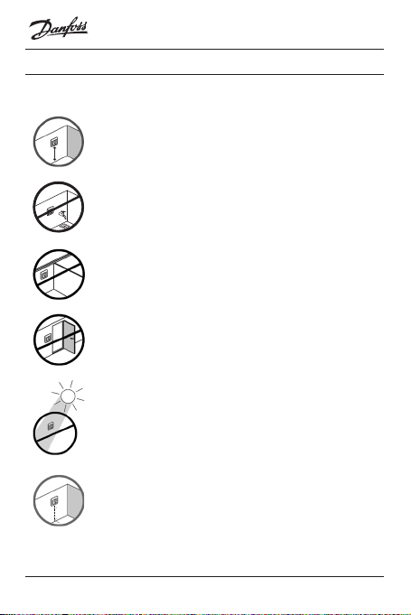
2 Mounting Instructions
Please observe the following placement guidelines:
Place the thermostat at a suitable height on the wall
(typically 80-170cm.).
The thermostat should not be placed in wet rooms.
Place it in an adjacent room and use oor sensor
only. Always place the thermostat according to local
regulation on IP classes and use oor sensor only.
Do not place the thermostat on the inner side of an
exterior wall.
Always install the thermostat at least 50 cm. from
windows and doors.
Do not place the thermostat in a way that it will be
exposed to direct sunlight.
Note: A oor sensor enables a more accurate
temperature control and is recommended in all oor
heating applications and mandatory under wooden
oors to reduce the risk of over-heating the oor.
Installation Guide6
Page 7

Danfoss ECtemp Next Plus
• Place the oor sensor in a conduit in an appropriate place
where it is not exposed to sunlight or draft from door
openings.
• Equally distant and >2cm from two heating cables.
• The conduit should be ush with the oor surface -
countersink the conduit if necessary.
• Route the conduit to the connection box.
• The bending radius of the conduit must be min 50mm.
Connect the thermostat according to the connection
diagram.
The screen of the heating cable must be connected to
the earth conductor of the power supply cable by using a
separate connector.
Note: Always install the oor sensor in a conduit in the
oor.
7Installation Guide
Page 8
Danfoss ECtemp Next Plus
SET
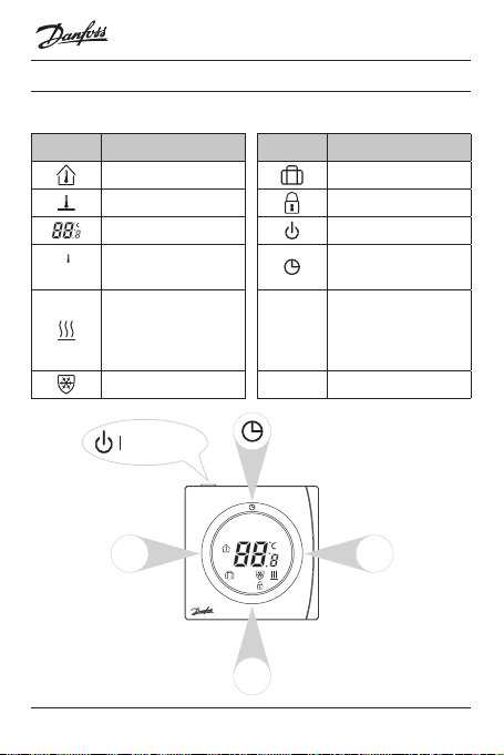
3 Symbols
The following symbols appears in the display:
Symbols Function description Symbols Function description
Room temperature Away mode
Floor temperature Child safety lock
Temperature indication Power ON/OFF
M
< >
Timer and program
operation
Mode change/check
oor temp./child
safety lock/parameters
setting
Up/down selectors
Set temperature
Floor heating, Active
Frost protection, Active
Power ON/OFF
<
<
SET
>
M
<
M
Installation Guide8
Page 9

Danfoss ECtemp Next Plus
4 Settings
4�1 Power ON/OFF
Switch thermostat ON/OFF by pressing button on top of
thermostat.
4�2 Initial Settings
Initial settings must be specied when the unit is activated
for the rst time:
Press M button for 6 seconds to enter the parameter setting
mode.
The upper digits indicate the parameter number.
Press M for parameter selection.
Press < or > to set the parameter range.
Complete all adjustments.
Press to exit ECtemp Next Plus settings, which is available
for this purpose.
To exit ECtemp Next settings automatic wait approx. 30
seconds.
9Installation Guide
Page 10

Danfoss ECtemp Next Plus
The digits indicate the set value as follows:
No� Parameter settings Settings range Default
P01 Working mode 01: Manual
02
02: Advanced Programmable Timer
P02 Temperature control
mode
01: Room and oor temp;
02: Only oor temp.;
01
03: Only room temp.*
P03 Maximum oor
temperature
20-30˚C (only for 01 in
P02)**
35˚C
P04 Frost protection 01: Enable; 02: Disable 01
P05 Frost protection
5-9˚C 5˚C
setpoint
P06 Timer display option 01: 24h; 02 12h 01
P07 Room temp. display
option at shutdown
01: No display surrent
temp.;
01
02: Display current temp.
* It will be possible to use only a room sensor. However, this option is not recommendable due to an increased risk of overheating the oor. See 4.9 Change to
Room control only
** P03 appears on relevant temperature control mode. See 4.10 Extending
Maximum oor temperature limitations to 45°C
4�3 Advanced Programmable Timer
The Advanced Programmable Timer mode enables the setting of a timer-controlled program for automatic comfort
Installation Guide10
Page 11

Danfoss ECtemp Next Plus
temperature, and an energy-saving lower setback temperature if standard room comfort temperature is not required.
The function consists of 2 programs:
P1 with 4 events in 5 days
(Mon. Tue. Wed. Thu. Fri.)
P1: Press and hold to display
Mo. Tu. We. Th. Fr.
P1, Event 1:
1. Use < or > to select the start
time.
2. Press to accept the
setting.
3. Use < or > to select the
temperature.
4. Press to accept the
setting.
P1, Event 2-4:
Repeat the Event 1 procedure
for programming Event 2-4.
P2 with 4 events in 2 days (Sat.
Sun.).
P2: Sa. Su. are now shown in
the display.
P2, Event 1:
1. Use < or > to select the start
time.
2. Press to accept the
setting.
3. Use < or > to select the
temperature.
4. Press to accept the
setting.
P2, Event 2-4:
Repeat the Event 1 procedure
for programming Event 2-4.
The thermostat will continue the 4-event program based
on the present time and day.
To set and change the room temperature temporarily:
1. Press < or > at any time to change the desired temperature value. SET is shown in the display.
11Installation Guide
Page 12

Danfoss ECtemp Next Plus
2. When releasing the < or >, the display returns to
showing the actual temperature. This temperature
change is only temporary and will be maintained only
until the next programmed setting!
A default program provides timer control if the customer
does not create own programs:
Event 1 Event 2 Event 3 Event 4
Days
Start
Mon -
Fri.
Sat -
Sun.
time
6:30
7:30
Temp� Start
20˚C
(27˚C)*
20˚C
(27˚C)*
time
8:30
9:30
Temp� Start
time
15˚C
16:30
(25˚C)*
20˚C
16:30
(27˚C)*
Temp� Start
time
20˚C
22:30
(27˚C)*
21˚C
22:30
(28˚C)*
Temp�
25˚C
(25˚C)*
25˚C
(25˚C)*
*Only oor temperature control mode.
4�4 Temperature Setting
Changing of desired temperature - press < or >.
SET is showed in the display.
Adjustment is changed in steps of 0.5°C
When releasing < or > again the display returns to normal
mode and shows actual temperature.
It will be possible to set the maximum oor temperature up
to 45°C.
Installation Guide12
Page 13

Danfoss ECtemp Next Plus
It would also be possible to use only one temperature
sensor. However, this option is not recommendable as this
cause an increased risk of overheating of the oor.
Extending maximum oor temperature and Setting into
room only mode – See point 4.9 and 4.10.
IMPORTANT: When the thermostat is used to control a
oor heating element in connection with a wooden oor or
similar material, always use a oor sensor and never set the
maximum oor temperature to more than 35 ° C.
Thermal
resistance
[m2K/W]
0.05 8 mm HDF
0.10 14 mm beech
0.13 22 mm solid
< 0.17 Max. carpet
0.18 22 mm solid
Examples of
Flooring
based laminate
parquet
oak plank
thickness suitable for oor
heating
for planks
Details Approximate
>800 kg/m328˚C
650 - 800
3
kg/m
>800 kg/m332˚C
acc. to EN
1307
450 - 650
3
kg/m
setting for
25˚C oor
temperature
31˚C
34˚C
35˚C
13Installation Guide
Page 14

Danfoss ECtemp Next Plus
4�5 Timer Setting
To adjust time and week day - press
Use < or > to adjust hours,
Press again to shift to minutes and use < or > for adjusting3
Press again to shift to weekdays and use < or > for selecting right day
Finish timer setting by pressing any other button or wait for
automatic exit after 6 sec. without operation
4�6 Safety Lock
Press M and > simultaneous to enable Safety lock.
To release safety lock press M and > simultaneous again.
4�7 Away Mode
Press M to get into Away mode
is showed in the display
Changing the desired temperature in Away mode
Press < or >.
SET is showed in the display
Adjustment in steps of 0.5°C
Press M to exit Away mode again
Installation Guide14
Page 15

Danfoss ECtemp Next Plus
4�8 Present Floor Temperature
Press M and hold – Press < within 6 sec also
start to ash and current oor temperature is be-
ing displayed.
Press any other button to exit or wait for automatic exit
after 6 sec. without operation
4�9 Change to Room control only
Switch Power OFF
Press M and Timer buttons simultaneously for approx. 10
seconds
Select Function P08: Only Room temperature control
Select Setting 01: Enable
Switch Power ON
Press M button for approx. 6 seconds
Select Parameter Setting P02: Temperature Control mode
Select Setting Range 03: Room Only mode
4�10 Extending Maximum oor temperature limita-
tion to 45°C
Power OFF
Press M and Timer buttons simultaneously for 10 seconds
into those parameters setting.
Select Function P07 (Table in 4.11): Setting range extension
for P06, P07 and P08
Select Setting 02: Maximum 45°C
15Installation Guide
Page 16

Danfoss ECtemp Next Plus
Adjust Maximum Floor temperature according to need up
to 45°C
Power ON
Press M button for 6 seconds
Select P03 (Table in 4.2): raise oor temperature limitation
higher than 35°C by using the >
4�11 Table for 4�9 Change to Room control only and
4�10 Extending Maximum Floor temperature
limitations to 45°C
No. Function Setting Factory default
Danfoss ECtemp™
Next Plus
P01 Room Sensor
Calibration
P02 Floor Sensor
Calibration
P03 Maximum
Room Temp.
Limitation
P04 Minimum
Room Temp.
Limitation
P05 Maximum
Room Temp.
Limitation
Oset:-10˚C to
+10˚C
Oset:-10˚C to
+10˚C
5-35˚C(Active in
Temperature Control
Mode 01)
5-35˚C(Active in
Temperature Control
Mode 01)
5-35˚C(Active in
Temperature Control
Mode 02)
0˚C
0˚C
35˚C
5˚C
35˚C
Installation Guide16
Page 17

Danfoss ECtemp Next Plus
P06 Minimum
Room Temp.
Limitation
P07 Setting range
extension for
P06, P07, P08
P08 Only room
temperature
control
5-35˚C(Active in
Temperature Control
Mode 02)
01: Max. 35˚C, 02:
Max. 45˚C
01: Enable, 02:
Disable
5 Error Codes
E1 Room sensor failure
E2 Floor sensor failure
EE EEPROM failure
Lo Temperature lower than 0˚C
Hi Temperature higher than 5˚C
All relay output will be turned o in all cases.
6 Warranty
YEAR
WARRANTY
5˚C
01
02
17Installation Guide
Page 18

7 Disposal Instruction
Danfoss ECtemp Next Plus
Installation Guide18
Page 19

Danfoss ECtemp Next Plus
19Installation Guide
Page 20

Danfoss ECtemp Next Plus
Installation Guide20
Page 21

Danfoss ECtemp Next Plus
21Installation Guide
Page 22

Danfoss ECtemp Next Plus
Installation Guide22
Page 23

Danfoss ECtemp Touch
Danfoss A/S
Electric Heating Systems
Ulvehavevej 61
7100 Vejle
Denmark
Phone: +45 7488 8500
Fax: +45 7488 8501
http://electricheating.danfoss.com/
Danfoss can accept no responsibility for possible errors in catalogues, brochures and other
printed material. Danfoss reserves the right to alter its products without notice. This also applies
to products already on order provided that such alterations can be made without subsequential
changes being necessary in specications already agreed. All trademarks in this material are
property of the respective companies. Danfoss and the Danfoss logotype are trademarks of
Danfoss A/S. All rights reserved.
Produced by Danfoss © 04/201608096226 & VIIOK202
Page 24

 Loading...