

Page 1

OperatingGuide
TermixATBTD
1.0TableofContents
1.0TableofContents.............................................1
........................................................................2
2.0Functionaldescription......................................3
3.0Safetynotes.....................................................4
3.1SafetyNotes–general............................................4
4.0Mounting........................................................5
4.1Mounting...........................................................5
4.2Start-up..............................................................7
5.0MountinginstructionsT ermixATBTDwall
cabinet............................................................8
5.1Mounting...........................................................8
6.0Design.............................................................10
6.1DesignTermixATBTD5pipes...................................10
6.2SchematicdiagramTermixATBTD5Pipes....................11
6.3DesignTermixATBTD4pipes...................................12
6.4SchematicdiagramTermixATBTD4Pipes....................13
7.0Controls..........................................................14
7.1DHWtemperaturecontrol........................................14
7.2Other.................................................................15
7.3Maintenance........................................................16
8.0Troubleshooting..............................................17
8.1Troubleshootingingeneral......................................17
8.2TroubleshootingDHW............................................18
8.3Disposal.............................................................19
9.0Declaration......................................................23
9.1Declarationofconformity........................................23
©Danfoss|2019.04VI.JV.Y4.02/LUK40692|1
Page 2
OperatingGuideTermixATBTD
2|©Danfoss|2019.04
VI.JV.Y4.02/LUK40692
Page 3
OperatingGuideTermixATBTD
2.0Functionaldescription
Districtheatingsubstationwithtankfordomestichotwater
preparationandwiththermostaticcontrol.Designedfor
wall-mounting.
Application
TheTermixATBTDsubstationisacompletesolutionforhot
water.TheTermixA TBTDisapplicableforsingle-familyhouses
orapartments.
Domestichotwater(DHW)
Thedomestichotwatercircuitconsistsofahotwatertankwithcoil
andself-actingthermostaticcontrolvalve.Thehotwatertankand
coilareenamelledandthetankcontainsamagnesiumanode.The
substationisdeliveredwithabuiltinsafetyvalve.
VI.JV.Y4.02/LUK40692
©Danfoss|2019.04|3
Page 4
OperatingGuideTermixATBTD
3.0Safetynotes
3.1SafetyNotes–general
Thefollowinginstructionsrefertothestandarddesignof
substation.Specialversionsofsubstationsareavailableon
request.
Thisoperatingmanualshouldbereadcarefullybeforeinstallation
andstart-upofthesubstation.Themanufactureracceptsno
liabilityfordamageorfaultsthatresultfromnon-compliancewith
theoperatingmanual.Pleasereadandfollowalltheinstructions
carefullytopreventaccidents,injuryanddamagetoproperty.
Assembly,start-upandmaintenanceworkmustbeperformedby
qualifiedandauthorizedpersonnelonly.
Pleasecomplywiththeinstructionsissuedbythesystem
manufacturerorsystemoperator.
Corrosionprotection
Allpipesandcomponentsaremadeofstainlesssteelandbrass.
Themaximumchloridecompoundsoftheflowmediumshouldnot
behigherthan150mg/l.
Theriskofequipmentcorrosionincreasesconsiderablyifthe
recommendedlevelofpermissiblechloridecompoundsis
exceeded.
Energysource
Thesubstationisdesignedfordistrictheatingastheprimary
sourceofenergy.However,alsootherenergysourcescanbeused
wheretheoperatingconditionsallowitandalwaysarecomparable
todistrictheating.
Application
Thesubstationisdesignedtobeconnectedtothehouse
installationinafrost-freeroom,wherethetemperaturedoesnot
exceed50°Candthehumiditydoesnotexceed60%.Donotcover
orwallupthesubstationorinanyotherwayblocktheentrance
tothestation.
Authorizedpersonnelonly
Assembly,start-upandmaintenanceworkmustbeperformedby
qualifiedandauthorizedpersonnelonly.
Pleaseobserveinstructionscarefully
Toavoidinjurytopersonsanddamagetothedevice,itisabsolutely
necessarytoreadandobservetheseinstructionscarefully.
Warningofhighpressureandtemperature
Beawareoftheinstallation’spermissiblesystempressureand
temperature.
Themaximumtemperatureoftheflowmediuminthesubstationis
120°C.
Themaximumoperatingpressureofthesubstationis10bar.PN16
versionsareavailableonenquiry.
Theriskofpersonsbeinginjuredandequipmentdamagedincreases
considerablyiftherecommendedpermissibleoperatingparameters
areexceeded.
Thesubstationinstallationmustbeequippedwithsafetyvalves,
however,alwaysinaccordancewithlocalregulations.
Choiceofmaterial
Choiceofmaterialsalwaysincompliancewithlocallegislation.
Safetyvalve(s)
Werecommendmountingofsafetyvalve(s),however,alwaysin
compliancewithlocalregulations.
Connection
Thesubstationmustbeequippedwithfeaturesthatensurethat
thesubstationcanbeseparatedfromallenergysources(also
powersupply).
Emergency
Incaseofdangeroraccidents-fire,leaksorotherdangerous
circumstances-interruptallenergysourcestothestationif
possible,andseekexperthelp.
Incaseofdiscolouredorbad-smellingdomestichotwater,closeall
shut-offvalvesonthesubstation,informtheoperatingpersonnel
andcallforexperthelpimmediately.
REACH
AllDanfossA/SproductsfulfilltherequirementsinREACH.
OneoftheobligationsinREACHistoinformcustomersabout
presenceofCandidatelistsubstancesifany,weherebyinform
youaboutonesubstanceonthecandidatelist:Theproduct
containsbrasspartswhichcontainslead(CASno:7439-92-1)ina
concentrationabove0.1%w/w.
Storage
Anystorageofthesubstationwhichmaybenecessarypriorto
installationshouldbeinconditionswhicharedryandheated.
Warningofhotsurface
Thesubstationhasgothotsurfaces,whichcancauseskinburns.
Pleasebeextremelycautiousincloseproximitytothesubstation.
Powerfailurecanresultinthemotorvalvesbeingstuckinopen
position.Thesurfacesofthesubstationcangethot,whichcancause
skinburns.Theballvalvesondistrictheatingsupplyandreturnshould
beclosed.
Warningoftransportdamage
Beforesubstationinstallation,pleasemakesurethatthesubstation
hasnotbeendamagedduringtransport.
IMPORTANT-Tighteningofconnections
Duetovibrationsduringtransportallflangeconnections,screwjoints
andelectricalclampandscrewconnectionsmustbecheckedand
tightenedbeforewaterisaddedtothesystem.Afterwaterhasbeen
addedtothesystemandthesystemhasbeenputintooperation,
re-tightenALLconnections.
4|©Danfoss|2019.04
VI.JV.Y4.02/LUK40692
Page 5
OperatingGuideTermixATBTD
4.0Mounting
4.1Mounting
Installationmustbeincompliancewithlocalstandardsand
regulations.
Districtheating(DH)-Inthefollowingsections,DHreferstothe
heatsourcewhichsuppliesthesubstations.Avarietyofenergy
sources,suchasoil,gasorsolarpower,couldbeusedasthe
primarysupplytoDanfosssubstations.Forthesakeofsimplicity,
DHcanbetakentomeantheprimarysupply.
Authorizedpersonnelonly
Assembly,start-upandmaintenanceworkmustbeperformedby
qualifiedandauthorizedpersonnelonly.
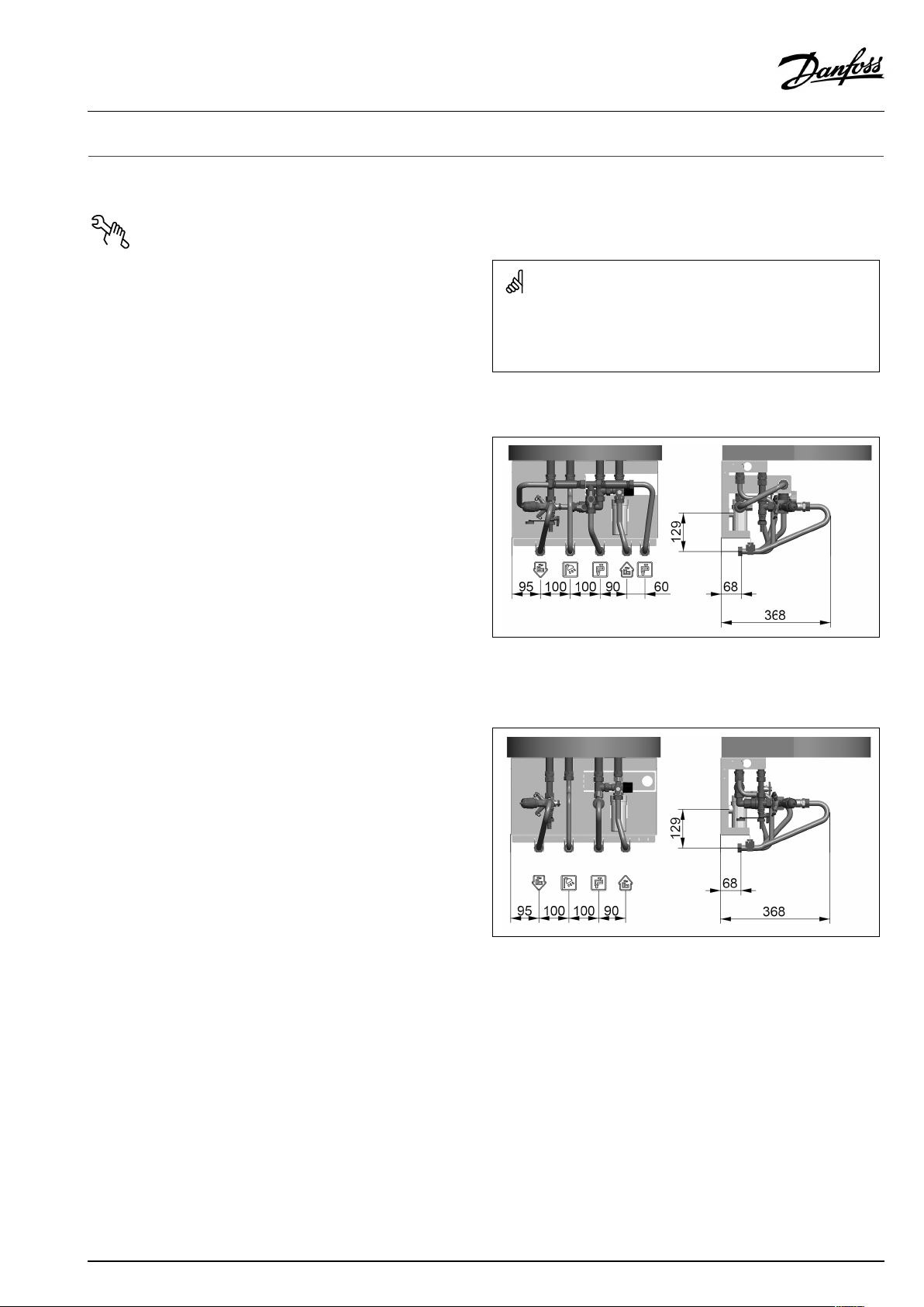
Connectionsizes:
Allconnections:
Dimensions(mm):
Withcover:
100L:H1180xW540xD520
150L:H1510xW540xD520
Weight(approx.):85–100kg
G¾”(int.thread)
TermixA TBTD5pipes
Thepipeplacementcandeviatefromtheshowndrawing.Pleasenote
themarkingsonthestation.
TermixA TBTD4pipes
VI.JV.Y4.02/LUK40692
Thepipeplacementcandeviatefromtheshowndrawing.Pleasenote
themarkingsonthestation.
©Danfoss|2019.04|5
Page 6

OperatingGuideTermixATBTD
4.1.1Installation
Mounting:
Adequatespace
Pleaseallowadequatespacearoundthesubstationformounting
andmaintenancepurposes.
Orientation
Thestationmustbemountedsothatcomponents,keyholes
andlabelsareplacedcorrectly.Ifyouwishtomountthestation
differentlypleasecontactyoursupplier.
Drillings
Wheresubstationsaretobewall-mounted,drillingsareprovided
inthebackmountingplate.Floormountedunitshavesupport.
Labelling
Eachconnectiononthesubstationislabelled.
Beforeinstallation:
Cleanandrinse
Priortoinstallation,allsubstationpipesandconnectionsshouldbe
cleanedandrinsed.
Tightening
Duetovibrationduringtransport,allsubstationconnectionsmust
becheckedandtightenedbeforeinstallation.
Unusedconnections
Unusedconnectionsandshut-offvalvesmustbesealedwitha
plug.Shouldtheplugsrequireremoval,thismustonlybedoneby
anauthorizedservicetechnician.
Installation:
Strainer
Ifastrainerissuppliedwiththestationitmustbefittedaccording
toschematicdiagram.Pleasenotethatthestrainermaybe
suppliedloose.
Connections
Internalinstallationanddistrictheatingpipesconnectionsmustbe
madeusingthreaded,flangedorweldedconnections.
6|©Danfoss|2019.04
VI.JV.Y4.02/LUK40692
Page 7
OperatingGuideTermixATBTD
4.2Start-up
Start-up,Directheating
Theshut-offvalvesshouldbeopenedandtheunitobservedas
itentersservice.Visualcheckingshouldconfirmtemperatures,
pressures,acceptablethermalexpansionandabsenceofleakage.
Iftheheatexchangeroperatesinaccordancewithdesign,itcanbe
puttoregularuse.
Afterwaterhasbeenaddedtothesystemandthesystemhasbeen
putintooperation,re-tightenALLconnections.
Re-thightenconnections
Afterwaterhasbeenaddedtothesystemandthesystemhasbeen
putintooperation,re-tightenALLconnections.
VI.JV.Y4.02/LUK40692
©Danfoss|2019.04|7
Page 8
OperatingGuideTermixATBTD
5.0MountinginstructionsTermixA TBTDwallcabinet
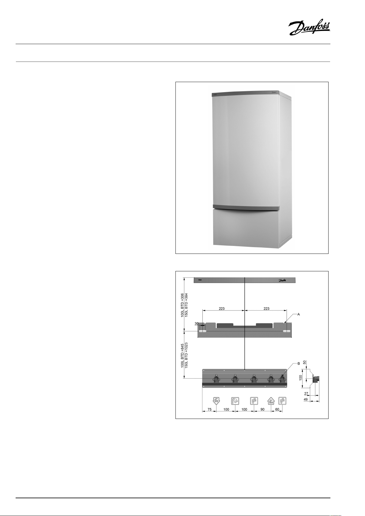
5.1Mounting
Wallbracket
MounttheWallbracketaccordingtotheDrawing.
UseAtocenterthetankonthebracket.
B-AllpipethreadsareISO½” .
Mountthecontainerunitinthewallbracket.
8|©Danfoss|2019.04
VI.JV.Y4.02/LUK40692
Page 9

OperatingGuideTermixATBTD
Sideplates
Fastentherightandleftsideplatesbyplacingthekeyholesover
thescrewsonthesidesofthewallbracket.
1Bottompanel
Slidetheslotsinthebottompanelontothe2bushesintheside
plates,andfastenthepanelwiththe2screwsinthefront.
2T opplate
Mountthetopplate.
3Frontcover
Mountthefrontcoverbyloweringthekeyholesontothescrews
inthesideplates.
4Clockpanel
Mounttheclockpanelbyloweringthekeyholesontothescrews
inthesideplates.
VI.JV.Y4.02/LUK40692
©Danfoss|2019.04|9
Page 10

OperatingGuideTermixATBTD
6.0Design
6.1DesignTermixATBTD5pipes
Yoursubstationmightlookdifferentthanthesubstationshown.
Designdescription
E
Hotwatertankwithcoil
S
Siphon
1A
Ballvalve,DVGW
2
Singlecheckvalve
10|©Danfoss|2019.04
4
Safetyvalve
20
Filling/drainvalve
41A
Fittingpiece,coldwatermains
59
Differentialpressure/temperatureregulatorwithflowlimiting
VI.JV.Y4.02/LUK40692
Page 11

OperatingGuideTermixATBTD
6.2SchematicdiagramTermixATBTD5Pipes
DHW
DCW
CWM
DH
Supply
DH
Return
Yoursubstationmightlookdifferentthantheschematicdiagramshown.
Schematicdescription
E
Hotwatertankwithcoil
1
Ballvalve
1A
Ballvalve,DVGW
2
Singlecheckvalve
DHW:DomesticHotWater
DCW:
CWM:
DHSupply:DistrictHeatingSupply
DHReturn:DistrictHeatingReturn
DomesticColdWater
Coldwatermains
4
Safetyvalve
20
Filling/drainvalve
41A
Fittingpiece,coldwatermains
59
Differentialpressure/temperatureregulatorwithflowlimiting
VI.JV.Y4.02/LUK40692
©Danfoss|2019.04|11
Page 12

OperatingGuideTermixATBTD
6.3DesignTermixATBTD4pipes
Yoursubstationmightlookdifferentthanthesubstationshown.
Designdescription
E
Hotwatertankwithcoil
S
Siphon
1A
Ballvalve,DVGW
2
Singlecheckvalve
4
Safetyvalve
20
Filling/drainvalve
59
Differentialpressure/temperatureregulatorwithflowlimiting
12|©Danfoss|2019.04
VI.JV.Y4.02/LUK40692
Page 13

OperatingGuideTermixATBTD
6.4SchematicdiagramTermixATBTD4Pipes
DHW
DCW
DH
Supply
DH
Return
Yoursubstationmightlookdifferentthantheschematicdiagramshown.
Schematicdescription
E
Hotwatertankwithcoil
1
Ballvalve
1A
Ballvalve,DVGW
2
Singlecheckvalve
DHW:DomesticHotWater
DCW:
DHSupply:DistrictHeatingSupply
DHReturn:DistrictHeatingReturn
6.4.1Technicalparameters
Technicalparameters
Nominalpressure:
Max.DHsupplytemperature:
DomesticColdWater
PN10
T–max=95°C
4
Safetyvalve
20
Filling/drainvalve
59
Differentialpressure/temperatureregulatorwithflowlimiting
VI.JV.Y4.02/LUK40692
©Danfoss|2019.04|13
Page 14

OperatingGuideTermixATBTD
7.0Controls
7.1DHWtemperaturecontrol
DHWtemperaturecontrol
TherearevarioustypesofDHWtemperaturecontrolusedin
Danfosssubstations.
DHWtemperatureshouldbeadjustedto45-50°C,asthisprovides
optimalutilisationofDHwater.AtDHWtemperaturesabove55°C,
thepossibilityoflimescaledepositsincreasessignificantly.
7.1.1AB-QMcontroller(45–60°)
QTisaself-actingthermostaticactuatordesignedtobeused
asreturntemperaturecontrolthermostatinone-pipeheating
systems.
QTisdedicatedtobeusedwithAB-QMautomaticbalancing&
controlvalve.
AB-QMDN10-20(45-60°C)
Temperaturesetting
20%
30%
40%
AB-QM(flow
setting)
Thevaluesareintendedasaguide.
50%
60%
70%
80%
90%
100%
QTSensorsetting(turns)
01
48,050,553,0
47,049,552,0
46,048,551,053,556,058,561,0
47,5
45,0
44,046,549,0
45,5
43,0
44,5
42,0
41,043,546,048,551,053,556,0
40,042,545,0
2
50,052,555,0
48,050,553,0
47,049,552,0
55,5
54,5
51,5
47,5
34
58,060,563,0
57,059,562,0
54,056,559,0
50,052,555,0
5
6
57,5
60,0
55,5
58,0
54,5
57,0
14|©Danfoss|2019.04
VI.JV.Y4.02/LUK40692
Page 15

OperatingGuideTermixATBTD
7.2Other
7.2.1Coldwatermeterfittingpiece
Thesubstationisequippedwithafittingpieceforcoldwatermeter.
Assemblyofcoldwatermeter:
1:Closeballvalves
Closetheballvalvesoncoldwater,ifthereiswateronthesystem.
2:Loosennuts
Loosenthenutsonthefittingpiece.
3:Removefittingpiece
Removethefittingpieceandreplaceitwiththecoldwatermeter.
Donotforgetthegaskets.
4:Tightenconnections
Aftermountingofthecoldwatermeterremembertocheckand
tightenallthreadedconnections.
7.2.2Siphon
PlacedtheSiphondirectlyundertheSafetyvalve.
Ensurethatthedrainpipehasaminimuminternaldiameterof
32mm.
VI.JV.Y4.02/LUK40692
©Danfoss|2019.04|15
Page 16

OperatingGuideTermixATBTD
7.3Maintenance
Thesubstationrequireslittlemonitoring,apartfromroutine
checks.Itisrecommendedtoreadtheenergymeteratregular
intervals,andtowritedownthemeterreadings.
RegularinspectionsofthesubstationaccordingtothisInstruction
arerecommended,whichshouldinclude:
Strainers
Cleaningofstrainers.
Meters
Checkingofalloperatingparameterssuchasmeterreadings.
Temperatures
Checkingofalltemperatures,suchasDHsupplytemperatureand
DHWtemperature.
Connections
Checkingallconnectionsforleakages.
Safetyvalves
Theoperationofthesafetyvalvesshouldbecheckedbyturning
thevalveheadintheindicateddirection.
Venting
Checkingthatthesystemisthoroughlyvented.
Authorizedpersonnelonly
Assembly,start-upandmaintenanceworkmustbeperformedby
qualifiedandauthorizedpersonnelonly.
Inspectionsshouldbecarriedoutminimumeverytwoyears.
SparepartscanbeorderedfromDanfoss.Pleaseensurethatany
enquiryincludesthesubstationserialnumber.
16|©Danfoss|2019.04
VI.JV.Y4.02/LUK40692
Page 17

OperatingGuideTermixATBTD
8.0Troubleshooting
8.1Troubleshootingingeneral
Intheeventofoperatingdisturbances,thefollowingbasicfeatures
shouldbecheckedbeforecarryingoutactualtroubleshooting:
•thesubstationisconnectedtoelectricity,
•thestrainerontheDHsupplypipeisclean,
•thesupplytemperatureoftheDHisatthenormallevel
(summer,atleast60°C-winter,atleast70°C),
•thedifferentialpressureisequaltoorhigherthanthenormal
(local)differentialpressureintheDHnetwork–ifindoubt,ask
theDHplantsupervisor,
•pressureonthesystem-checktheHEpressuregauge.
Authorizedpersonnelonly
Assembly,start-upandmaintenanceworkmustbeperformedby
qualifiedandauthorizedpersonnelonly.
VI.JV.Y4.02/LUK40692
©Danfoss|2019.04|17
Page 18

OperatingGuideTermixATBTD
8.2TroubleshootingDHW
ProblemPossiblecauseSolution
ToolittleornoDHW.
Taptemperaturetoohigh;DHWtapload
toohigh.
Temperaturedropduringtapping.
Thermostaticcontrolvalvedoesnotclose
Strainerinsupplyorreturnlineclogged.Cleanstrainer(s).
DHWcirculationpumpoutoforderorwith
toolowsetting.
Defectiveorcloggednon-returnvalve.
Noelectricity.Check.
Wrongsettingofautomaticcontrols,ifany.Toadjustanelectroniccontrollerfor
Scalingoftheplateheatexchanger.
Defectivemotorizedvalve.Check(usemanualfunction)–replace.
Defectivetemperaturesensors.
Defectivecontroller.
DCWisbeingmixedwiththeDHW,e.g.ina
defectivethermostaticmixingvalve.
Defectiveorcloggednon-returnvalveon
circulationvalve.
Thermostaticvalveadjustedtoatoohigh
level.
Scalingoftheplateheatexchanger.
LargerDHWflowthanthesubstationhas
beendesignedfor.
TemperaturedifferencebetweenDH
supplyandDHWsetpointtoolow.
Checkcirculationpump.
Replace–clean.
DHW,pls.noteenclosedinstructionsfor
electroniccontroller.
Replace–rinseout.
Check–replace.
Check–replace.
Check–replace. Hotwaterinsometapsbutnotinall.
Replace–clean.
Check–set.
Replace–rinseout.
ReduceDHWflow.
Lowerthesetpointtemperatureorincrease
theDHsupplytemperature.
18|©Danfoss|2019.04
VI.JV.Y4.02/LUK40692
Page 19

OperatingGuideTermixATBTD
8.3Disposal
Disposal
Thisproductshouldbedismantledanditscomponents
sorted,ifpossible,invariousgroupsbeforerecycling
ordisposal.
Alwaysfollowthelocaldisposalregulations.
VI.JV.Y4.02/LUK40692
©Danfoss|2019.04|19
Page 20

OperatingGuideTermixATBTD
20|©Danfoss|2019.04
VI.JV.Y4.02/LUK40692
Page 21

OperatingGuideTermixATBTD
21|©Danfoss|2019.04
VI.JV.Y4.02/LUK40692
Page 22

OperatingGuideTermixATBTD
22|©Danfoss|2019.04
VI.JV.Y4.02/LUK40692
Page 23

OperatingGuideTermixATBTD
9.0Declaration
9.1Declarationofconformity
Category0withoutelectricalequipment
VI.JV.Y4.02/LUK40692
©Danfoss|2019.04|23
Page 24

OperatingGuideTermixATBTD
24|©Danfoss|2019.04
VI.JV.Y4.02/LUK40692
 Loading...