

Page 1
Data sheet
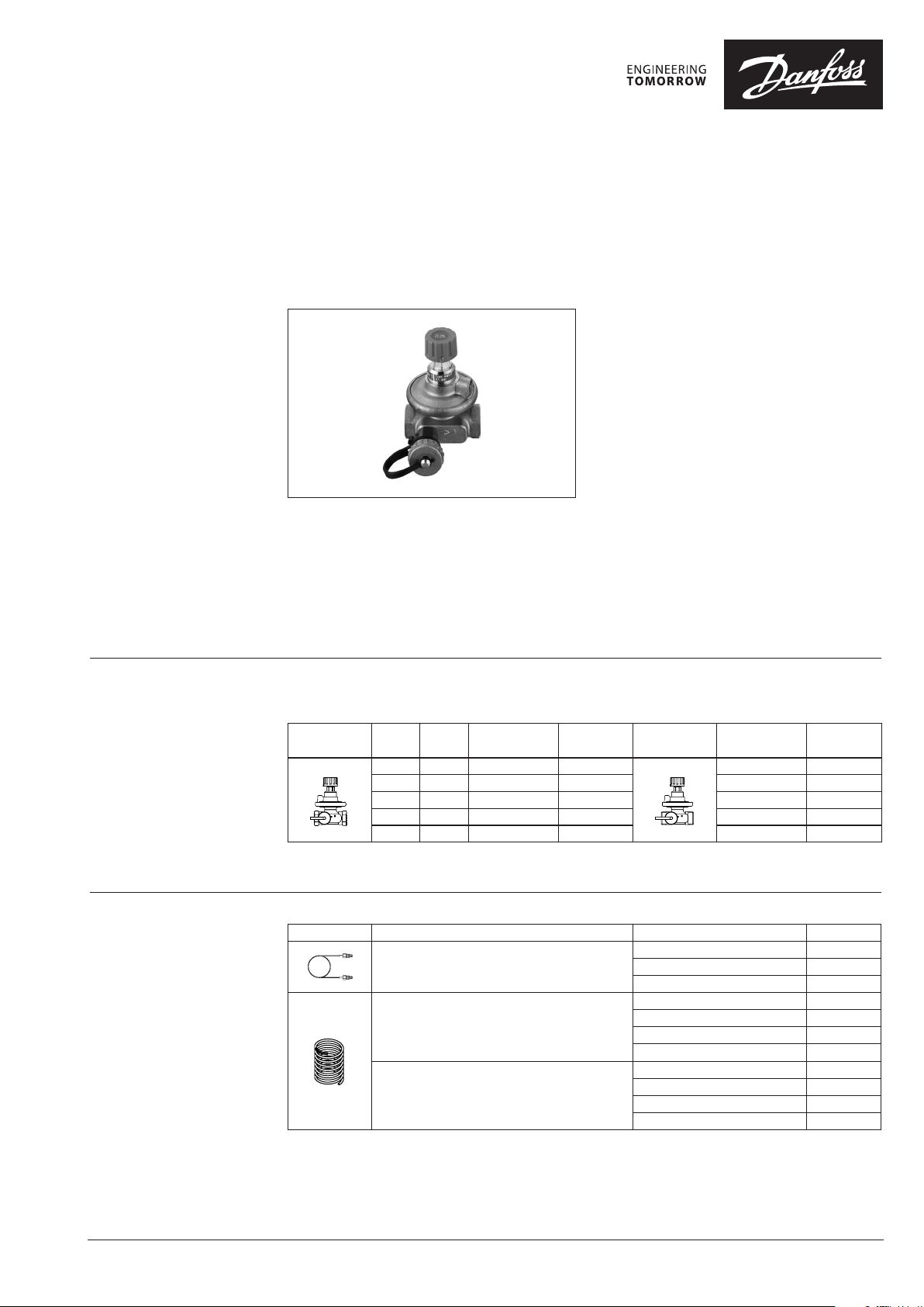
Automatic balancing valve
ASV-P (DN 15-40)
Description
Ordering
ASV balancing valves are designed to guarantee
high quality of the automatic balancing by:
- a pressure released cone,
- an adapted membrane for every valve
dimension which provide constant quality
performance for all sizes.
A 90° angle between all service features (shut-off,
draining, measuring) allows an easy access under
any installing condition.
ASV valves (DN 15-40) are packaged in styropore
(EPS) which can be used for insulation at
ASV-P valves are automatic balancing valves
with fixed setting (10 kPa) for creating optimal
hydronic balance in residential heating systems.
The setting can be increased to 20 or 30 kPa
by spring replacement. Spring can be replaced
under pressure.
temperatures up to 80 °C. An insulation cap is
available as an accessory for insulation at higher
temperatures (up to 120 °C).
ASV-P valves are to be mounted in return pipe,
in combination with partner valves mounted
in f low pipe. As a partner valve ASV-M/I/BD are
recommended.
ASV-P balancing valve, inclusive in the box: 1.5 m impulse tube (G ⁄ A) and drain cock (G ⁄ A)
Constant differential pressure 10 kPa ; can be upgraded to 20 or 30 kPa setting respectively
Internal thread
k
Typ e DN
15 1.6 Rp ½ 003L7621 G ¾ A 003L7626
20 2.5 Rp ¾ 003L7622 G 1 A 0 03L7627
25 4.0 Rp 1 0 03L7623 G 1¼ A 003L7628
32 6.3 Rp 1¼ 003L7624 G 1½ A 003L762 9
40 10 Rp 1½ 003L7625 G 1¾ A 003L7630
Note: for whole rang e of ASV partner valves, spa re parts and accessories pl ease refer to ASV datasheet.
VS
3
(m
/h) (I SO 7/1) (ISO 228/1)
Code No. Ty pe
External thread
Code No.
Accessories and spare parts
© Danfoss | 2017.07
Typ e Description Comments/connection Co de No.
1.5 m 003L 8152
Impulse tube, with O-rings
ASV-P 20 kPa spring (yellow)
ASV-P 30 kPa spring (green)
2.5 m 003Z0690
5 m 003L 8153
DN 15 003 L8182
DN 20 003L8183
DN 25 003L8184
DN 32 / DN 40 003 L8185
DN 15 003L8192
DN 20 003L 8193
DN 25 003L 8194
DN 32 / DN 40 003 L8195
VD.A9.L1.02 | 1
Page 2
Data sheet Automatic balancing valves ASV-P
Technical data
Application
Nominal diameter DN 15- 40
Max. pressure
Test pressure 25
Differential pressure over the valve kPa 10 -150
Temperature °C –20 … 120
Materi al of parts in cont act with water
Valve body Brass
Cone ASV-P DZR brass
Membrane / O-rings EPDM
Spring Stainless steel
1)
Please note tha t the maximum admissible dif ferential pressure across t he valve 150 kPa should also not be e xceeded at partial lo ad.
bar
16 (PN 16)
1)
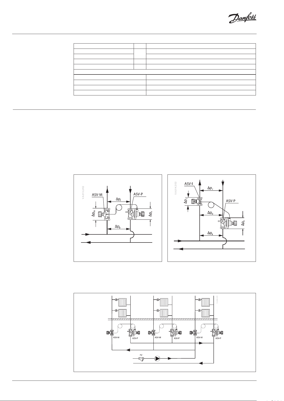
There are two basic configurations when using
ASV partner valves (ASV-BD, ASV-I, ASV-M,
MSV-F2):
- partner valve outside the control loop (Fig. 1).
Recommended configuration: it results in best
performance since whole controlled pressure
range is available to the riser. Flow limitation
is done on each terminal unit in the riser (for
example, RA-N with presetting on radiator,
- partner valve inside control loop (Fig. 2).
Offers flow limitation on the riser however
part of the controlled pressure range is used
by pressure drop on partner valve (p
recommended when flow limitation on each
). It is
i
terminal units is not possible.
etc).
2 | © Danfoss | 2017.07
Fig. 1 Setting of ASV-P = Δpriser Fig. 2 Setting of ASV-P = ∆priser + ∆p
i
ASV-BD can be used outside or inside control loop by choice of which measuring nipple is open.
To be used outside control loop, blue measuring nipple needs to be open. In this position, flow
verification can be done (default position). To be used inside control loop, red measuring nipple
needs to be open. In this position, flow verification & flow verification can be done.
Fig. 3 ASV in riser / typical heating application (general example)
VD.A9.L1.02
Page 3
Data sheet Automatic balancing valves ASV-P
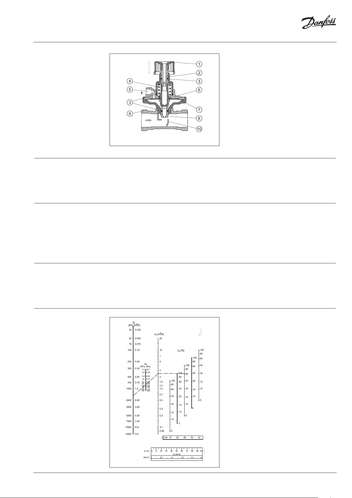
Design
1. Shut-off knob
2. Shut-off spindle
3. O-ring
4. Reference spring
5. Impulse tube connection
6. Diaphragm element
7. Control diaphragm
8. Pressure-relieved valve cone
9. Valve body
10. Seat
Dimensions - insulation
Pressure testing
ASV-P must be installed in the return pipe with
flow in the direction of the arrow on the valve
body. Partner valves (ASV-M/I/BD, MSV-F2 must
be installed in the flow pipe, with flow in the
Max. test pressure is 25 bar. When pressure
testing the system you must secure that both
sides of the membrane have the same static
pressure to prevent damage of the pressure
controller. That means the impulse tube must
be connected and any needle valves must be
open. If ASV-P is installed in combination with
The ASV-P is designed to maintain constant
differential pressure across a riser. Via an internal
connection and together with the reference
spring, pressure in the return pipe acts on the
underside of the control diaphragm ⑦ while via
an impulse tube ⑤, pressure in the f low pipe
acts on the top of the diaphragm. In this way the
balancing valve maintains a fixed differential
pressure of 10 kPa.
The setting can be increased to 20 or 30 kPa
by spring replacement. Spring can be replaced
under pressure. The ability to increase the
setting is especially useful in case of trouble
shooting. It gives insurance that design flow can
be achieved even if calculation doesn’t match
actual installation.
direction of the arrow on the valve body. The
impulse tube must be installed between partner
valve and ASV-P. The impulse tube must be
flushed through before installation.
ASV-M both valves must be open or closed (both
valves must be in the same position!). If ASV-P
is installed in combination with ASV-I /ASV-BD
both valves must be open. During this operation
(closing or opening the valves) please make sure
that there is never lower pressure on upper side
of the membrane to prevent damaging it.
Starting
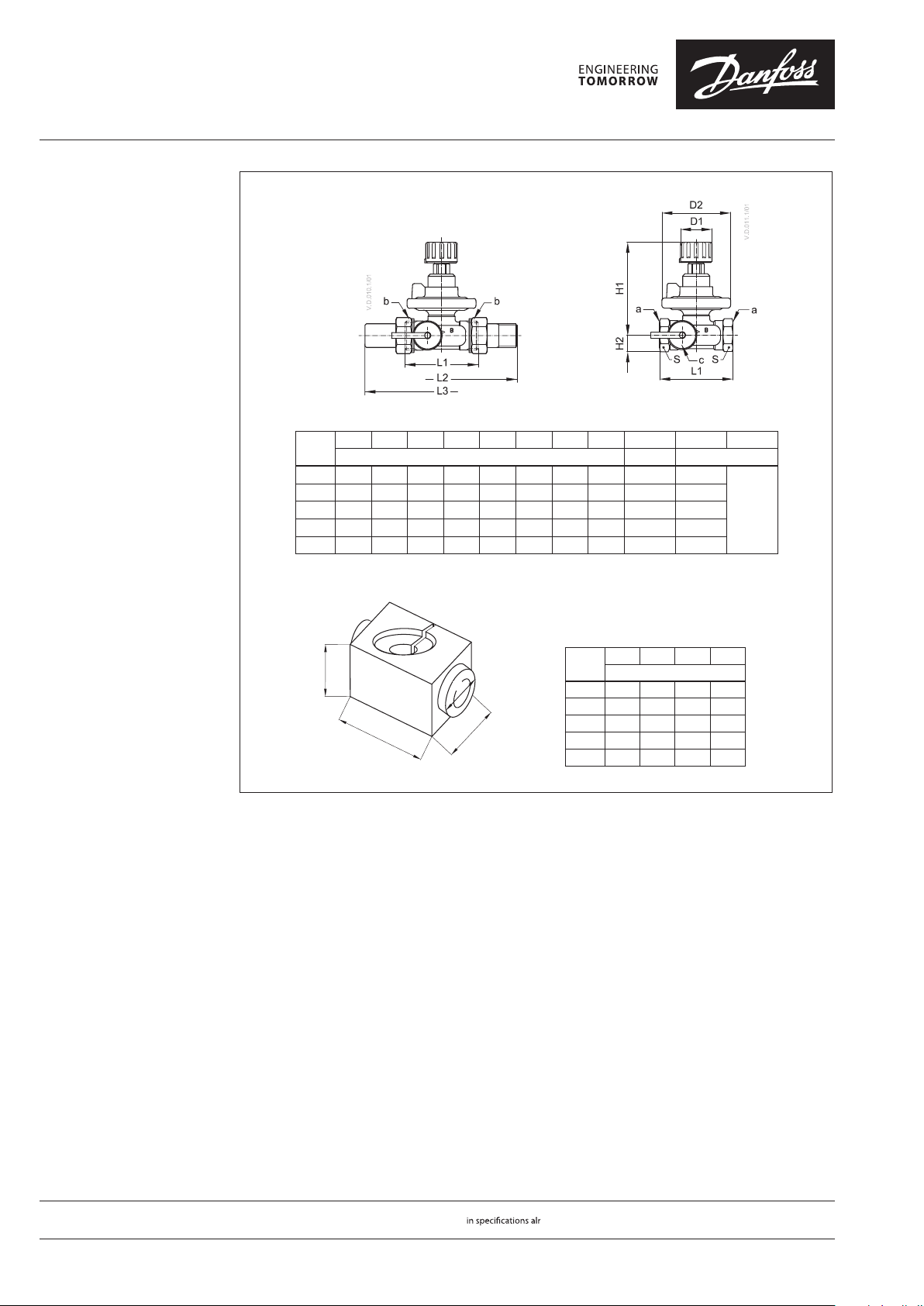
Appendix A-Sizing diagram
During system start – opening the shut-off on
ASV and partner valve-please secure that there
is the same static pressure on both sides or
higher pressure on upper side of the membrane.
If filling is done by opening ASV-P and partner
valve, please make sure there is a pressure on the
upper side of the membrane by opening partner
valve first before ASV-P is opened.
VD.A9.L1.02
© Danfoss | 2017.07 | 3
Page 4
Danf
already on order pro
All trademarks in this material are property of the respec
Data sheet Automatic balancing valves ASV-P
Dimensions
L1 L2 L3 H1 H2 D1 D2 S a b c
DN
65 120 139 82 15 28 61 27 Rp ½ G ¾ A
15
75 13 6 159 103 18 35 76 32 Rp ¾ G 1 A
20
85 155 169 132 23 45 98 41 Rp 1 G 1¼ A
25
95 17 2 179 165 29 55 122 50 R p 1¼ G 1½ A
32
100 206 184 170 31 55 12 2 55 R p 1½ G 1¾ A
40
mm IS O 7/1 ISO 228/1
G ¾ A
Insulation
A B C D
A
D
BC
DN
15 61 110 111 37
20 76 120 136 45
25 100 135 155 55
32 118 148 160 70
40 118 14 8 180 70
mm
oss can accept no responsibility for possible errors in catalogues, brochures and other printed material. Danfoss reserves the right to alter its products without notice. This also applies to products
vided that such alterations can be made without subsequential changes being necessary eady agreed.
4 | © Danfoss | DHS-SRMT/SI | 2017.07
tive companies. Danfoss and the Danfoss logotype are trademarks of Danfoss A/S. All rights reserved.
VD.A9.L1.02
 Loading...