

Page 1
Data sheet
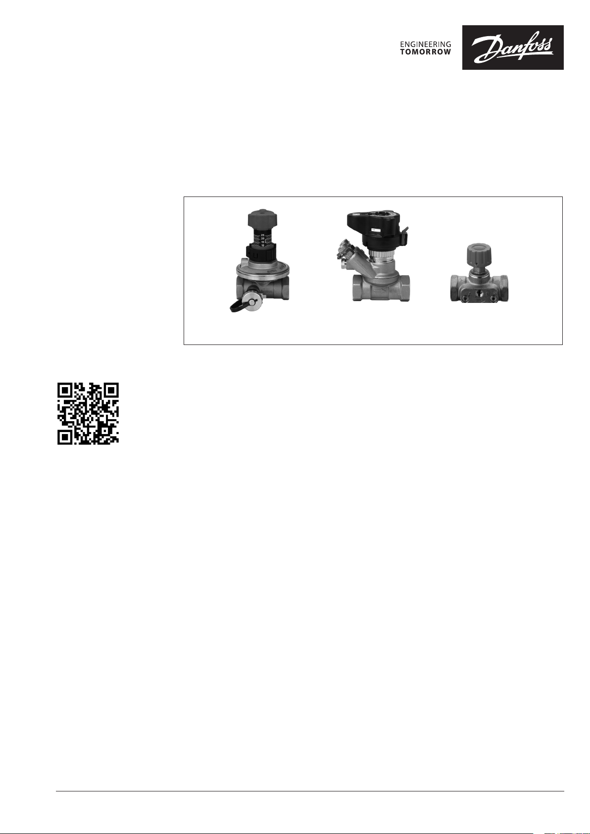
Automatic balancing valves
ASV DN 15-50 (4th gen.)
ASV-PV ASV-BD ASV-M
DN 15-50 DN 15-50 DN 15-50
Description
ASV whiteboa rd animation
ASV valves are automatic balancing valves.
Together with Danfoss presetting radiator
thermostatic valves they are part of the Danfoss
two-pipe solution and are perfect for creating
optimal hydronic balance in residential two-pipe
heating systems.
One of the major challenges in heating systems
is a lack of good hydronic balancing, caused
by differential pressure, which is changing
constantly and unpredictably in the heating
system. This results in complaints from residents
about poor indoor comfort, noise and high
energy bills.
Trying to solve these complaints, larger pumps
are often installed to improve - especially under
heated - circulation of the water. Unfortunately,
this affects pressure differentials and energy
consumption within the system even more.
Besides, the higher pressure differential, the
greater the noise from the system, particularly
from radiator valves.
ASV automatic balancing valves ensure an
optimal pressure differential for control valves
as well as the correct flow within the individual
risers at all times. This is the reason why DIN
18380 requires control of differential pressure at
partial loads. The ASV automatically creates an
optimal hydronic balance within the installation,
whether under full or partial load. This balance is
never disrupted.
The ASV valves can also be used in cooling
applications (fan coil, chilled beam, etc) with
variable flow, to secure an automatic hydronic
balance (see general ASV datasheet for details).
Benefits
Installing an ASV combination ensures:
• Fewer complaints:
ASV makes the system more reliable, with less
disturbances such as noisy radiators, under
heating of rooms far away from the heat
source, or over-heating of rooms close to the
heat source. Fewer complaints means less
call-backs to installer to solve the complaints.
• Improved indoor comfort:
ASV provides stable pressure conditions
to radiator or floor heating control valves
resulting in more accurate room temperature
control.
• Lower energy bills:
Higher energy efficiency is contributed by
solving overheating problem and ensuring
more accurate temperature control. Proper
balance prevents overflows thus resulting
in low return water temperature, which
improves energy efficiency of condensing
boilers and district heating systems.
• Simplicity:
ASV divides the piping system in pressure
independent zones, typically individual
risers or apartments so complex and time
consuming calculation and commissioning
methods are not needed anymore. It also
allows a gradual connection of zones to
the main constructions without additional
balancing.
• Ease of use:
The new generation of ASV automatic
balancing valves is even simpler to use than
before. The improved setting scale can now
be set without using an allen key, saves time
for the installer during commissioning and
maintenance of the system while new flushing
function saves time during flushing of pipe
network.
© Danfoss | 2016.11
VD.A9.J2.02 | 1
Page 2
Data sheet Automatic balancing valves ASV
Applications ASV balancing valves are designed to guarantee
high quality of automatic balancing by:
• a pressure released cone,
• an adapted membrane for valve dimension
which provides constant quality performance
for all sizes,
• linear and accurate setting scale that makes
setting required ∆p easy.
• low required 10 kPa pressure drop on ASV-PV
valve contributes to smaller pump head.
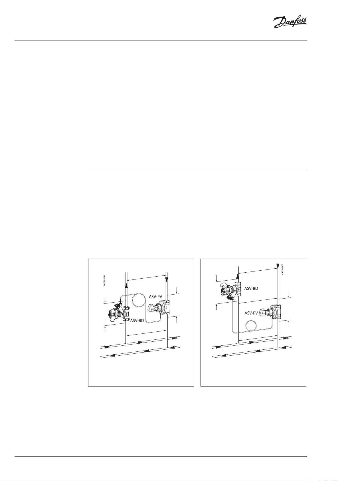
The Danfoss ASV solution comprises an
automatic balancing valve ASV-PV and an
associated partner valve (Fig. 1 and 2). The ASVPV is a differential pressure controller, fitted into
the return pipe.
The partner valve is fitted into the supply pipe.
Both valves are connected to each other using a
mpulse tube.
There are two basic configurations when using
ASV partner valves:
Partner valve outside the control loop (Fi g .1).
Recommended valve ASV-BD (default
configuration: blue test plug needs to be open,
red is in closed position) or ASV-M:
It results in best performance since whole
controlled pressure range is available to the riser.
Flow limitation is done on each terminal unit in
the riser (for example, RA-N with presetting on
radiator, etc).
The pressure controller has a factory setting
of 10 kPa or 30 kPa, perfect for typical radiator
based heating systems. Of course it can easily
be adjusted to another setting using the setting
scale. If the pressure differential tends to become
greater than this setting, then the ASV automatic
balancing valve immediately reacts and keeps
the pressure differential constant. By this the
pressure in the controlled riser or loop does not
increase due to any system load changes.
ASV balancing valves have integrated service
functions such as: *Flushing
*shutt-off
*draining
Shut-off function is separated from the setting
mechanism.
Partner valve inside the control loop (Fig.2).
Recommended valve ASV-BD (red test plug
needs to be open, blue is in closed position):
Offers flow limitation on the riser however part of
the controlled pressure range is used by pressure
drop on partner valve (∆pp). It is recommended
when flow limitation on each terminal is not
possible.
p
r
p
r
v
p
p
1)
Please note tha t blue test plug on ASV-BD ne eds to be open
(default co nfiguration)
Fig. 1 Setting of ASV-PV = ∆p
outside the control loop)
1)
p
a
(partner valve
riser
p
p
p
1)
Please note tha t the red test plug on ASV-BD ne eds to be
open and blu e test plug closed
Fig. 2 Setting of ASV-PV = p
p
p
1)
o
v
p
a
+ p
riser
p
ASV-BD can be used outside or inside the control loop by choice of which measuring nipple is open.
Change of configuration can be done under pressure - simply by closing/opening test plugs.
Configuration inside the control loop (default position) allows flow verification, while configuration
outside the control loop allows flow limitation.
2 | © Danfoss | 2016.11
VD.A9.J2.02
Page 3
Data sheet Automatic balancing valves ASV
Applications (continuous)
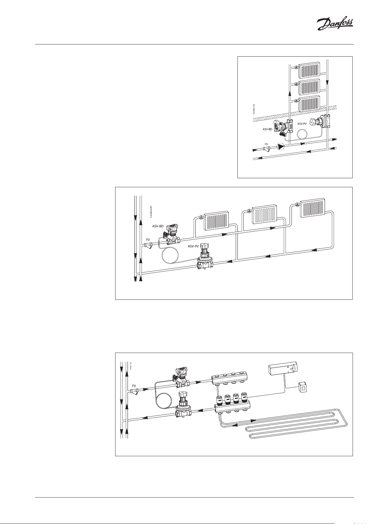
ASV valves are to be used in radiator heating
systems to control the differential pressure in
risers (Fig. 3) or horizontal loops - mostly used in
new installation (Fig. 4). To limit the flow for every
radiator, the thermostatic radiator valve with presetting function is used together with a constant
pressure provided by the ASV, thus providing
balanced heat distribution.
Fig. 3 ASV in vertical riser / t ypical radiator heating
application (general example)
Fig. 4 ASV in horizontal loop / t ypical radiator heating application (general example)
ASV valves are also a perfect solution in floor
heating systems (Fig. 5). To limit the flow, every
manifold with integrated presetting should be
used together with a constant pressure provided
by an ASV-PV valve.
ASV-BD
ASV-PV
Fig. 5 ASV in manifold for floor heating system
Alternatively the flow for the whole manifold
can be limited by using the setting function of
the ASV-BD. Due to its small dimensions the ASV
automatic balancing valves are easy to install in a
wall mounted box for floor heating manifolds.
VD.A9.J2.02
© Danfoss | 2016.11 | 3
Page 4
Data sheet Automatic balancing valves ASV
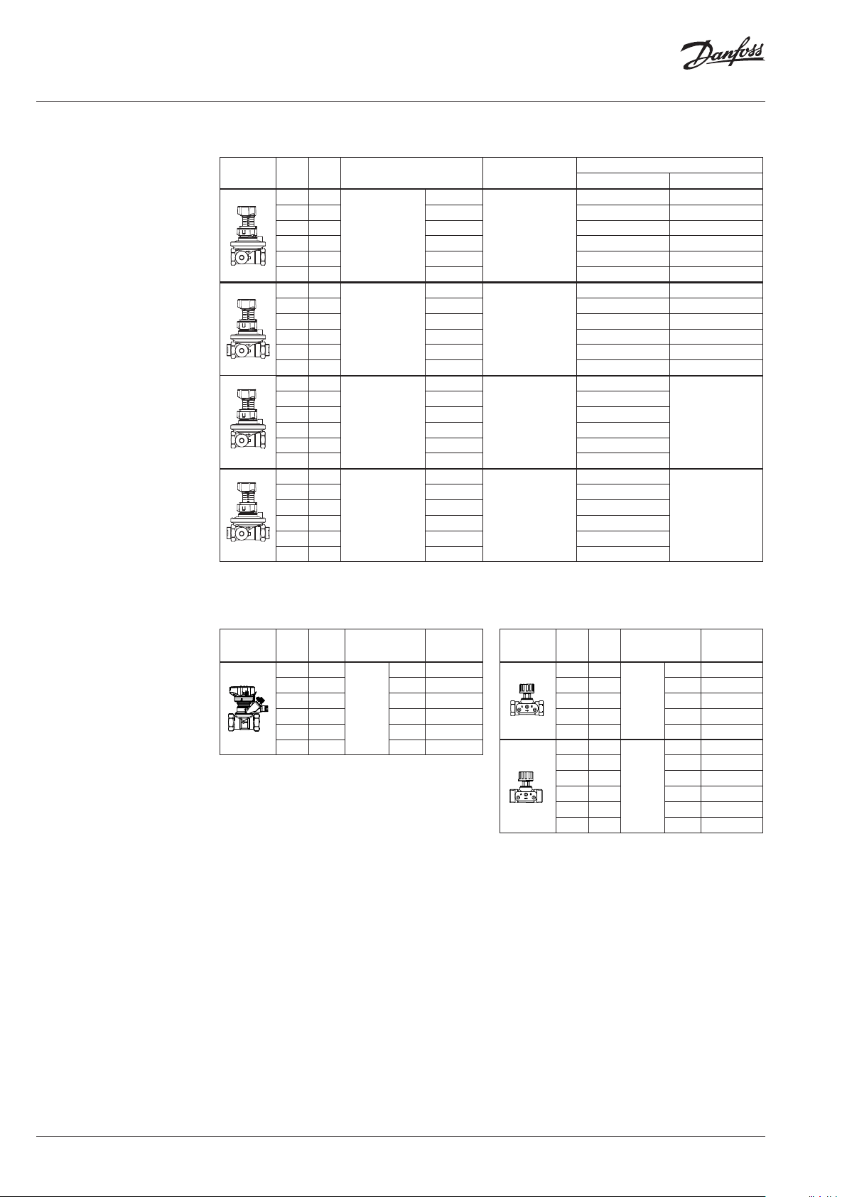
Ordering
ASV-PV balancing valve, included in the box:
1,5 m impulse tube (G ⁄ A)
k
Typ e DN
VS
(m3/h) (kPa)
15 1, 6
20 2,5 Rp ¾ 003Z5502 003Z5602
25 4,0 Rp 1 003Z5503 003Z5603
32 6,3 Rp 1¼ 003Z5504 003Z5604
40 10,0 Rp 1½ 003Z5505 003Z5605
50 16, 0 Rp 2 003Z5506 003Z56 06
15 1, 6
20 2,5 G 1 A 003Z5512 00 3Z5612
25 4,0 G 1¼ A 00 3Z5513 0 03Z5 613
32 6,3 G 1½ A 00 3Z5514 -
40 10,0 G 1¾ A 0 03Z5515 -
50 16, 0 G 2¼ A 003Z5516 -
15 1, 6
20 2,5 Rp ¾ 003Z5542
25 4,0 Rp 1 003Z5543
32 6,3 Rp 1¼ 003Z5544
40 10,0 Rp 1½ 003Z5545
50 16, 0 Rp 2 003Z5546
15 1, 6
20 2,5 G 1 A 003Z5552
25 4,0 G 1¼ A 003Z5553
32 6,3 G 1½ A 003Z5554
40 10,0 G 1¾ A 003Z5555
50 16, 0 G 2¼ A 003Z5556
Connection
Rp ½
Internal thread
IS O 7/1
G ¾ A
External thread
ISO 228/1
Rp ½
Internal thread
IS O 7/1
G ¾ A
External thread
ISO 228/1
∆p setting range Code No.
without insulation with EPP insulation
003Z 5501 003Z 5601
5-25
003 Z55 11 0 03 Z56 11
5-25
003Z5 541
20-60
003Z5551
20-60
-
-
ASV-BD shut-off valve, multifunctional partner
valve (shut-off, rotating measuring station) and
EPP insulation
k
Typ e DN
VS
(m3/h)
15 3,0
20 6,0 Rp ¾ 003Z4042
25 9,5 Rp 1 003Z4043
32 18 Rp 1¼ 003Z404 4
40 26 Rp 1½ 003Z4045
50 40 Rp 2 003Z4046
Connection Code No.
Rp ½ 003Z4 041
Internal
thread
IS O 7/1
ASV-M shut-off valve, without test plugs and
with EPS insulation
k
Typ e DN
VS
(m3/h)
15 1, 6
20 2,5 Rp ¾ 0 03L7692
25 4,0 Rp 1 0 03L7693
32 6,3 Rp 1¼ 0 03L7694
40 10 Rp 1½ 0 03L7695
15 1, 6
20 2,5 G 1 A 003L7697
25 4,0 G 1¼ A 0 03L7698
32 6,3 G 1½ A 003L7699
40 10 G 1¾ A 003L7700
50 16 G 2¼ A 003L7702
Connection Code No.
Rp ½ 003L7691
Internal
thread
IS O 7/1
G ¾ A 003L7696
External
thread
ISO 228/1
4 | © Danfoss | 2016.11
VD.A9.J2.02
Page 5
Data sheet Automatic balancing valves ASV
Ordering (continuous)
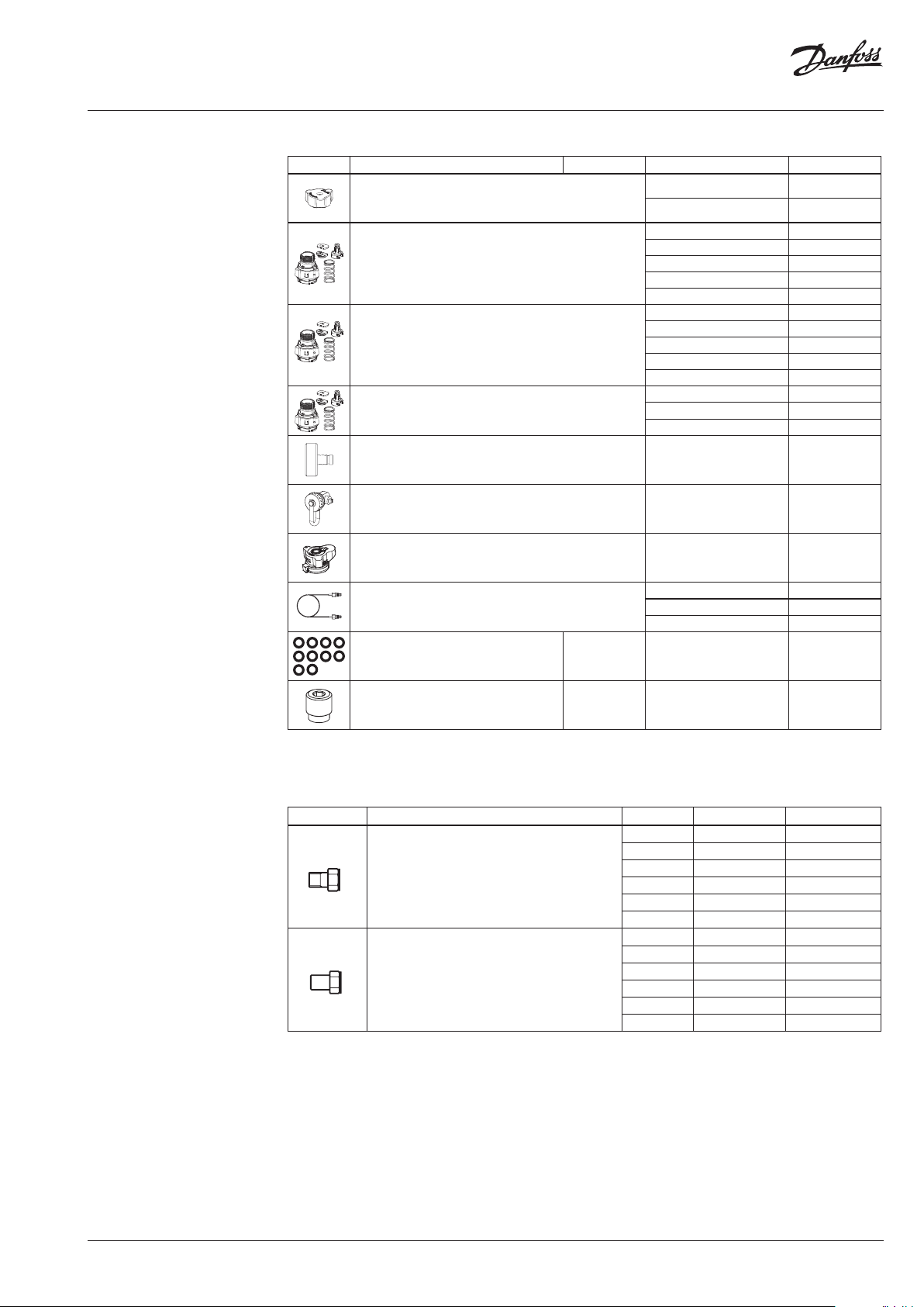
Spare parts
Typ e Description Comments Connection/Dimension Code No.
ASV-PV handle
ASV-PV Service kit 20- 60 kPa
ASV-PV Service kit 5-25 kPa
ASV-PV Service kit 20-80 kPa
Differential pressure measuring connector For ASV-PV drain connection 003L8143
ASV-PV drain connection DN 15-50 00 3L8141
ASV-BD handle
Impulse tube, with O-rings
2)
DN 15-25 003Z7855
DN 32-50 003Z7857
DN15 -20 003 Z7831
DN 25 003Z7832
DN 32 003Z7833
DN 40 003Z7834
DN 50 003Z7835
DN15 -20 0 03Z7841
DN 25 003Z7842
DN 32 003Z7843
DN 40 003Z7844
DN 50 003Z7845
DN 32 003Z7836
DN 40 003Z7837
DN 50 003Z7838
1,5 m 003L 8152
2,5 m 003Z0690
5 m 0 03L8153
003Z4652
O-ring for impulse tube Set of 10 pieces 2,90 × 1,7 8 003L8175
Plug for impulse tube connection ASV-BD/M Set of 10 pieces G ⁄ A 0 03L 8174
1)
With handle
2)
For com plete range of ASV-BD accessori es please refer to LENO™ MSV-BD datashe et.
Accessories - Fittings
Typ e Comments to pipe to valve Code No.
R / DN 15 003Z0232
R / DN 20 0 03Z0233
Tailpiece threaded (1 pcs.)
Tailpiece welding (1 pcs.)
R 1 DN 25 003Z0234
R 1 / DN 32 003Z0235
R 1/ DN 4 0 003Z0273
R 2 DN 50 (2 /”)
DN 15
DN 20
DN 25
DN 32
DN 40
DN 50 DN 50 (2 /”)
DN 15 003Z0226
DN 20 003Z0227
DN 25 003Z0228
DN 32 003Z0229
DN 40 003Z0271
00 3Z0274
003Z0272
VD.A9.J2.02
© Danfoss | 2016.11 | 5
Page 6
Data sheet Automatic balancing valves ASV
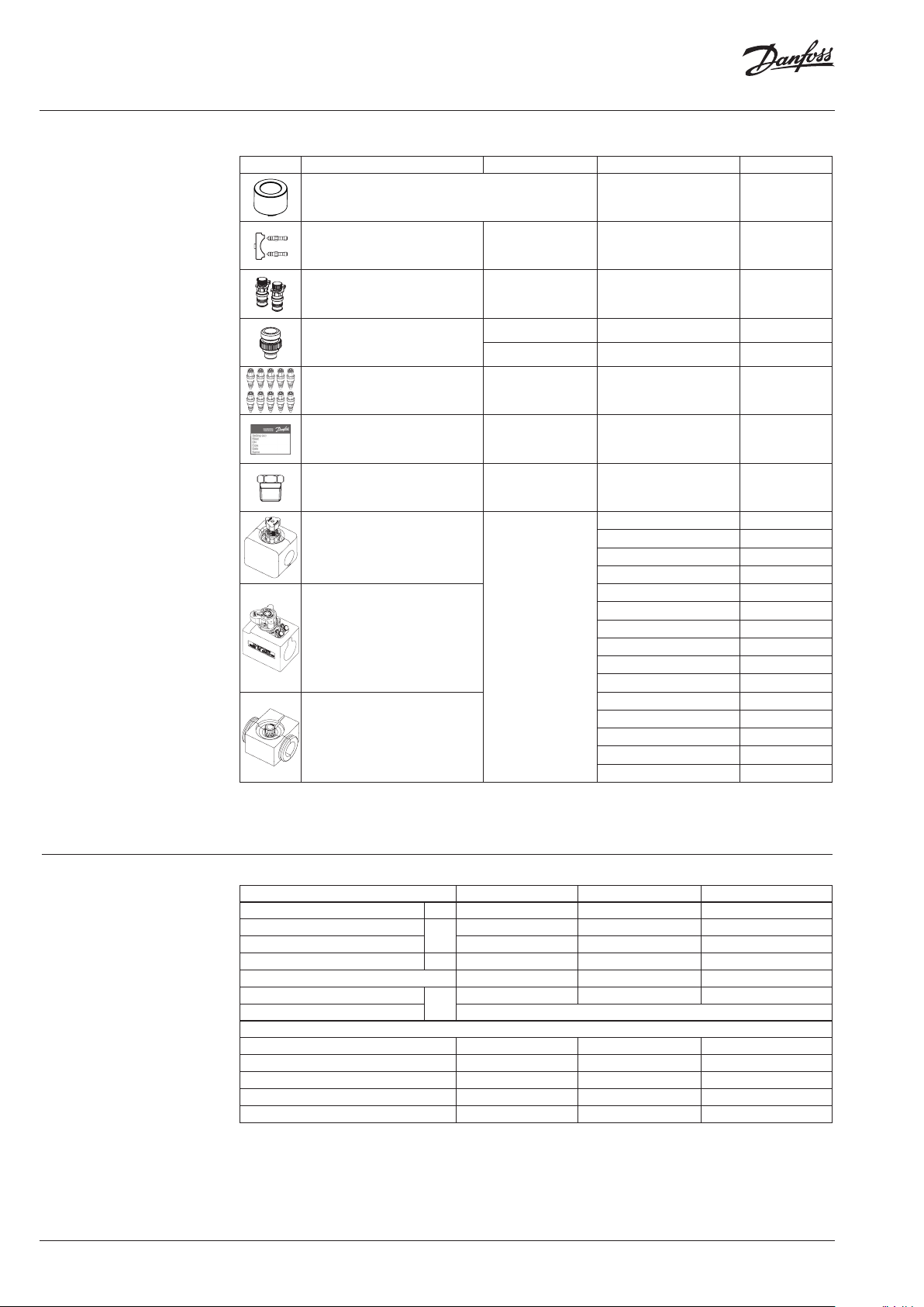
Accessories
Typ e Description Comments Connection/Dimension Code No.
ASV-PV flushing accessory 003Z7850
Two test plugs and one locking plate For ASV-M, rectus t ype 00 3L8145
3 mm test plugs, 2 pcs For ASV- BD
ASV-BD drain connection
Plastic impulse tube with connec tors
and adapters
Commissioning label
2)
½” hose connection 003Z4096
¾” hose connection 003Z4097
For making set of 10
pieces
Set of 10 pieces DN15 -50 003Z7860
1)
3)
Plug for connecting impulse tube G ⁄-R ¼ connection 00 3L8151
EPP insulation cap for ASV-PV
EPP insulation cap for ASV-BD
max. 120 °C
EPP insulation cap for ASV-M
1)
For com plete range of ASV-BD accessori es please refer to LENO™ MSV-BD datashe et.
2)
To be fitte d on insulation
3)
10m of impulse tube
003Z4662
003Z0689
DN 15-20 003Z7800
DN 25 0 03Z7802
DN 32 003Z7803
DN 40-50 003Z7804
DN 15 003Z4781
DN 20 0 03Z4782
DN 25 0 03Z4783
DN 32 003Z4784
DN 40 003Z4785
DN 50 0 03Z4786
DN 15 00 3L8170
DN 20 0 03L 8171
DN 25 0 03L8172
DN 32 00 3L817 3
DN 40 0 03L8139
Technical data
6 | © Danfoss | 2016.11
Typ e ASV-P V ASV-M ASV-B D
Nominal diameter DN 15- 50 15- 50 15-50
Max. pressure (PN)
Test pressure 25 25 30
bar
Differential pressure over the valve kPa 10-250 10-150
Shut Off leakage No visible leakage
Working temperature
Storage and transport temperature –40 … 70
°C
16 16 20
1)
2)
2)
D
10-2 50
2)
A
0 … 120 –20 … 120 –20 … 120
Material of parts in contact with water
Valve body Brass Brass DZR brass
Cone DZR brass Brass
Membrane / O-rings EPDM EPDM EPDM
Spring Patent wire - -
Ball - - Brass / chromium plated
1)
Pl ease note that the maximum adm issible differential p ressure across the valve 150 kPa should also not be excee ded at partial load.
2)
ISO 5208
VD.A9.J2.02
Page 7

Data sheet Automatic balancing valves ASV
Design
1. Spring guide
2. Shut-off handle
3. Spring
4. Differential pressure setting
spindle
5. Setting scale
6. O-ring
7. Locking ring
8. Impulse tube connection
9. Diaphragm element
10. Control diaphragm
11. Internal connection
12. Valve body
13. Pressure-relieved valve cone
14. Seat
ASV handling video
ASV-PV is a compact differential pressure
controller designed to guarantee
high quality of automatic balancing. Innovative
construction and ease of use are incorporated
into the valve with the following features:
• integrated membrane part into valve body ⑫,
• easy setting with locking function ⑦,
• flushing function,
• shutt-off function, separated from presetting
• membrane adapted to valve size.
Via an internal connection and together with the
reference spring ③, pressure in the return pipe
acts on the lower side of the control diaphragm
⑩ while via an impulse tube ⑧, pressure in the
flow pipe acts on the top of the diaphragm. In
this way the balancing valve maintains adjusted
differential pressure.
Partner valves ASV-BD/M are to be used together
with the automatic balancing valves ASV-PV to
control differential pressure in the risers.
The valves factory set to 10 kPa or 30 kPa.
They can be easily adjusted to another setting
using setting scale ⑤. Turning the setting ring
clockwise increases the setting; turning it counter
clockwise reduces the setting.
Fig. 6 ASV-PV
1. Handle with setting scale
2. Spindle head
3. Rotation lock
4. Te st plug
5. Valve top
6. Spindle
7. Impulse tube connection
8. Closing bush
9. Hose connection
10. Rotating measuring station
11. Throttle bush
12. Supporting screw
13. Ball seat
14. Ball
15. Valve body
1. Shut-off handle
2. Shut-off spindle
3. O-rings
4. Valve cone
5. Seat
6. Valve body
ASV-BD is a combined presetting and shut-off
valve with a range of unique features:
• high kv values for small pressure losses,
• partner valve position inside or outside the
control loop (see page 2 for details), can even
be changed after the valve is already installed
and under pressure,
• numeric presetting scale, visible from multiple
angles ①,
• easy locking of presetting,
• rotating measuring station ⑩ with built-in
test plugs for 3 mm needles,
• drain function via drain connection accessory
(Code No. 003Z4096 or 003Z4097) ⑦ ,
• removable handle for easy mounting,
• shut-off function separated from presetting,
• open-closed colour indicator.
ASV-BD can be used outside or inside the control
loop (see page 2 for details) dependent on which
test plug is open. Configuration is changeable
under pressure.
The shut-off function features a ball valve, which
only requires a 90 degree turn to shut the valve
completely.
ASV-M is designed to shut-off the pipe flow.
ASV-M has a connection for an impulse tube to
ASV-PV. It can be equipped with test plugs for
flow measuring (which are sold separately as
accessories).
ASV-BD valve is supplied with two test plugs for
3 mm needles. A twin bracket enables the user to
connect both needles simultaneously.
Fig. 7 ASV-BD DN 15-50
VD.A9.J2.02
Fig. 8 ASV-M
© Danfoss | 2016.11 | 7
Page 8

Data sheet Automatic balancing valves ASV
Sizing
Q
≤ Q ≤ Q (at 10 kPa)
min
Fig. 9
diagram A and B in Appendix.
Column diagram for sizing Q =required design flow ASV valves at ∆pv = 10 kPa. For different ∆pv values use
We recommend to size the diameter of ASV-PV
valves by using Fig 9. Maximum flow rates are
based on 10 kPa differential pressure over ASV-PV
valve which allows perfect control performance of
ASV-PV and saves energy, while minimal nominal
flow allow controllability close to zero.
After ASV-PV valves have been sized the same
dimension of partner valve ASV-BD / ASV-M valve
should be selected.
Example:
Given:
Pipe flow 200 l/h, pipes DN 15
Solution:
Horizontal line intersects the column for the
valve DN 15 which can therefore be selected
as required size (in case more columns
are intersected the smaller valve size is
recommended.)
For detailed sizing see examples on pages 14 and
15. For different ∆pV (differential pressure over
the valve) see diagrams in Appendix A.
Connection between valves size and pipe size
Kv values per particular dimension were
designed to cover flow range according to
VDI 2073 with water velocity of up 0,8 m/s, at
differential pressure of 10 kPa over the valve. As
long as the water velocity in the pipe is between
0,3 and 0,8 m/s dimension of the valve should be
equal to pipe dimension.
This rule is derived out of the fact that Kv values
per particular dimension were designed to cover
flow range according to VDI 2073 at differential
pressure of 10 kPa over the ASV-PV valve.
8 | © Danfoss | 2016.11
VD.A9.J2.02
Page 9

Data sheet Automatic balancing valves ASV
kPa 5bar 0,05
0,4
9,0
Kv
Q
p
2
2
p
1
Sizing-design examples
p
r
v
p
p
p
p
a
Fig . 10
1. Example
Given:
Radiator system with thermostatic radiator valves
with pre-setting function.
Desired flow for the riser (Q): ...........................900 l/h
Minimal available pressure
for that riser (∆pa) ..................................................60 kPa
Estimated pressure drop over the riser
at the desired flow (∆pr) .....................................10 kPa
Wanted:
• Valve type
• Valve size
Since radiator valves have pre-setting function
ASV-M is selected.
ASV-PV should control 10 kPa pressure over the
riser that means that 50 kPa out of 60 will be
disposed over two valves.
∆pv + ∆pp = ∆pa−∆pr = 60−10 = 50 kPa
We presume that dimension DN 25 is the right
dimension for this example (please mind that
both valves should be of the same dimension). As
ASV-M DN 25 is to be fully open pressure drop is
calculated by following equation:
∆pa ≥ ∆pp + ∆pr + ∆pv
Δpv Pressure drop across ASV-PV
Δpp Pressure drop across ASV-M valve
Δpr Necessary pressure for the riser
Δpa Available pressure for the riser
2. Example
Correcting the flow with the differential pressure
setting.
Given:
Measured flow for the riser Q1 ........................ 900 l/h
ASV-PV valve’s setting ∆pr ................................ 10 kPa
Wanted:
New valves’ setting to increase the flow for 10 %,
Q2 = 990 l/h.
Setting on the ASV-PV valve:
When needed setting of the control pressure can
be adjusted to particular value or 20-60 kPa.
With increasing/decreasing the setting it is
possible to adjust flow trough the riser, terminal
or similar. (100 % increase of control pressure will
increase the flow for approx. 41 %)
2
Q
2
pp
12
Q
10,0
990
900
2
kPa 21
If we increase the setting to 12 kPa flow will be
increased to 10 % to 990 l/h.
or by reading from diagram in
Appendix A, fig. C
as follows:
Draw horizontal line from 0,9 m3/h (~900 l/h)
trough the line that depicts dimension DN 25.
From the intersection draw vertical line to read
that pressure drop is 5 kPa.
Pressure drop over ASV-PV valve is therefore:
∆pv= (∆pa-∆pr)−∆pp = 50 kPa−5 kPa = 45 kPa
as can be read from diagram in Appendix A,
Fig. A.
VD.A9.J2.02
© Danfoss | 2016.11 | 9
Page 10

Data sheet Automatic balancing valves ASV
hm1,5
03,0
880,0
p
Q
k
3
v
v
Sizing-design examples
(continuous)
p
r
p
p
p
o
v
p
p
a
Fig . 11
3. Example
Limiting the flow with ASV-BD valve
Given:
Desired flow for the branch (Q): .....................880 l/h
ASV-PV and ASV-BD (DN 25)
Setting on the ASV-PV valve (∆po) ..................10 kPa
Estimated pressure drop over
the riser at desired flow (∆pr) ............................. 7 kPa
∆pa ≥ ∆pp + ∆pr + ∆p
Δpv Pressure drop across ASV-PV valve
Δpp Pressure drop across ASV-BD valve
Δpo Pressure drop in the riser including ASV-BD
Δpa Available pressure for the riser
Δpr Pressure drop in the riser excluding ASV-BD
v
4. Example
Floor heating application with ASV-PV on return
manifold
Given:
Pressure drop (largest loop): ............................. 16 kPa
Pressure drop manifold: ........................................2 kPa
Flow demand of manifold: ............................... 900 l/h
Connection pipe: .....................................................DN25
Required:
Setting of the ASV-BD valve to achieve desired
flow
Solution:
When needed setting of the ASV-BD can be
adjusted to perform flow limitation function.
ASV-BD namely is inside the control loop of the
pressure controller therefore adjusting ASV-BD
would result in adjusting flow limitation. Red test
plug on ASV-BD valve needs to be open (blue
one in closed position). (General rule is that 100
% increase of kv value will increase the flow for
100 %).
The result can be read as well from diagram in
Appendix A, Fig.B.
At desired flow pressure drop over the entire
branch is 7 kPa. Without using ASV-BD flow
trough the branch at fully open control valve
will be 19 % higher thus causing overflow (7 kPa
allow 880 l/h, while 10 kPa allow 1.050 l/h). With
adjusting the ASV-BD DN 25 pre-setting to 4,3 kv
value (5,1 m3/h) we will limit the flow to 880 l/h as
desired.
Wanted:
• Valve size (DN)
• Valve setting (∆po)
ASV-PV DN25 / 5-25 kPa is selected (same size as
connection pipe).
Since the valve setting is given by sum. of total
pressure loss:
manifoldloopo
kPa 18 = Pa2k + kPa 16 =Δp + Δp =Δp
Setting 18 kPa on ASV-PV setting scale is needed.
10 | © Danfoss | 2016.11
This value is obtained by following calculation:
∆pp = ∆po − ∆pr = 10 − 7 = 3 kPa.
Alternative, flow limitation can also be done by
bigger ∆p setting on ASV-PV valve.
VD.A9.J2.02
Page 11

Data sheet Automatic balancing valves ASV
Installation
ASV-PV should be installed in the return pipe
with flow in the direction of the arrow on the
valve body. Partner valves (ASV-M/BD) should
be installed in the flow pipe, with flow in the
direction of the arrow on the valve body. The
impulse tube should be installed between
partner valve and ASV-PV.
The impulse tube should be flushed through
from flow pipe direction before connection to
ASV-PV.
Small installation dimensions enable easy
installation of ASV valves even in very limited
space. A 90° angle between all service features
(shut-off, draining, setting, measuring) allows an
easy access under any installing condition.
Setting Δp setting
The setting of differential pressure can be easily
changed using the setting scale, which saves
time for the installer during maintenance of the
system.
① ② ③
Draining
The drain connection on ASV-PV or ASV-BD can
be used for water tapping and filling.
Use the following procedure to drain via ASV-BD
valve:
1. Close opened test plug.
2. Remove the impulse tube.
3. Dismount the hose connection.
4. Fit drain connection accessory
(Code No. 003Z4096 or 003Z4097).
5. Blue test plug opens the outlet while red test
plug opens the inlet. Make sure not to use
more than max. 3 turns. Drain connection and
test plugs can rotate to any position.
Use the following procedure to set the desired
differential presure:
1. Unblock the setting ①.
2. Make the setting by rotating of scale to desire
value ②.
3. Block the setting back to final position ③.
Factory presetting
Δp setting range (kPa) kPa
5 - 25 10
20 - 60 30
Pressure testing
Click
Max. test pressure ............................................... 25 bar
When pressure testing the system the impulse
tube should be connected and all partner valves
should be open.
Click
−
p
+
VD.A9.J2.02
© Danfoss | 2016.11 | 11
Page 12

Data sheet Automatic balancing valves ASV
Flushing
Measurement of flow and
differential pressure
ASV-PV valves provides ability to flush the system
from flow pipe. Use the following procedure for
flushing the system:
1. Ensure system is filled with water
2. Dismount shut off handle ① and fit flushing
accessory ② (Code No. 003Z7850) on the
ASV-PV valve spring guide.
3. Rotate by hand flushing accessory clockwise
➊
003Z7850
Click
DN32-50 DN15 -25
to end position before flushing the system ③.
4. Flushing of the system should be done with
flow in direction of the arrow on the valve
body.
5. After flushing the system rotate counter
clockwise to starting position.
Note:
Make sure system is f illed with water before mo unting flushing
accessory to ensu re differential pressure d oes not exceed 5 bar.
❸➋
Differential pressure across the ASV-BD valve can be taken by:
• Measuring: by using Danfoss PFM or any other measuring device. ASV-BD is equipped with two test
plugs so that the differential pressure across the valve can be measured.
• Using the pressure drop graph for ASV-BD (Appendix A, fig B), where the actual differential
pressure across a valve can be converted to actual flow.
Note: When measurin g sized flow, all radiator thermos tat sensors should be fully o pen (nominal flow).
Measurement of differential pressure (Δpr)
across riser.
Fit a measuring connector (Code No. 003L8143)
on the ASV-PV balancing valve drain connection
(DN 15-50). Measurements should be taken
between :
• the test plug at ASV-BD valve (blue test plug
needs to be open-factory position) and the
measuring connector on the ASV-PV.
• the test plug at ASV-M valve (port B) and the
measuring connector on the ASV-PV.
Flow verification (in case ASV-BD is used
outside the controlled loop)
Use the following procedure:
1. Blue test plug on ASV-BD needs to be open
(factory position).
2. ASV-BD setting is at maximum value.
3. Flow can be measured using Danfoss PFM or
other brand of measuring instrument.
4. If pressure drop across the valve is too low for
reliable flow measurement, ASV-BD needs
to be set to lower setting to achieve high
enough pressure drop across the valve.
12 | © Danfoss | 2016.11
VD.A9.J2.02
Page 13

Data sheet Automatic balancing valves ASV
Pump optimization ∆p measurement can also be used to optimize
the pump head – it is important to measure on
the last (index) riser of the system and at full
system load (all TRV’s fully open).
The pump head can be decreased until no more
than the minimal required pressure is available
on the last riser.
Troubleshooting
Check the following if the riser valve does not
function correctly:
1. Is the flow direction through the valve correct?
2. Is the impulse tube fitted correctly and are any
test plugs open?
3. Is the valve shut-off open?
Installation heights To ease installation of ASV-PV where space is
limited, installation heights can be reduced.
Valve is turned to max setting and blue knob can
be removed.
For advanced users: see installation guide for
ASV-PV upgrade kit for further information on
installation heights.
With observation of the ∆p while reducing the
pump speed, the goal is to optimize the pump
at the lowest possible setting while making sure
that enough pressure and flow is available.
H min.
DN H min.
15 80
20 80
25 100
32 150
40 150
50 15 0
Insulation
Fittings
ASV-PV (versions with insulation) and ASV-BD
valve are supplied together with EPP insulation cap.
Insulation cap offers click on feature for fast and
easy mounting on the valve. Insulation cap in EPP is
offered for use at higher temperatures, up to 120 °C.
ASV-M valve is supplied with EPS insulation
packaging, which can be used as insulation in
systems where the temperature does not exceed
80 °C under continuous operation.
For ordering see Accessories and spare parts
table.
Both materials (EPS and EPP) are approved in
accordance with fire class standard B2, DIN 4102.
For valves with external thread Danfoss offers
threaded or welded tailpieces as accessory.
Materials:
Nut ................................................................................brass
Tailpiece welding .....................................................steel
Tailpiece threaded ..................................................brass
For ordering see Accessories and spare parts
table.
ASV-M
ASV-BD / ASV-PV
VD.A9.J2.02
© Danfoss | 2016.11 | 13
Page 14

Data sheet Automatic balancing valves ASV
Dimensions
H
b b
S
c
a
L
1
Internal thread (ISO 7/1)
L
2
L
3
L
4
External thread (ISO 228/1)
ASV-PV
L1L2L3L4H 1)H
DN
mm I SO 7/1 ISO 228/1
15 65 85 14 0 159 111 96 116 27 Rp ½ G ¾ A
20 75 100 161 184 111 96 116 32 Rp ¾ G 1 A
25 85 110 180 194 13 6 113 14 3 41 Rp 1 G 1¼ A
32 95 121 206 184 191 18 3 213 50 Rp 1¼ G 1½ A
40 10 0 136 242 220 200 192 222 55 Rp 1½ G 1¾ A
50 130 166 280 250 203 195 225 67 Rp 2 G 2¼ A
1)
at 10 kPa or 30 kPa factory se tting
2)
at 25 kPa or 60 kPa settin g
3)
at 5 kPa or 20 kPa settin g
min
2)H
3)S a b c
max
ASV-BD
L H S a
mm ISO 228/1
65 92 27 G ½
15
75 95 32 G ¾
85 98 41 G 1
95 121 50 G 1¼
32
100 125 55 G 1½
130 12 9 67 G 2
G⁄
DN
H
20
25
S
a
a
L
40
50
G ¾ A
14 | © Danfoss | 2016.11
ASV-M
DN
15
20
25
32
40
50
D
1
1
a
H
2
H
L
a
S
S
L
1
L
1
L
H
2
3
H
1
2
b
D
1
b
L
1
L
2
L
3
S a b
mm IS O 7/1 ISO 228/1
65 120 139 48 15 28 27 Rp ½ G ¾ A
75 136 159 60 18 35 32 Rp ¾ G 1 A
85 155 169 75 23 45 41 Rp 1 G 1¼ A
95 172 179 95 29 55 50 Rp 1¼ G 1½ A
100 206 18 4 100 31 55 55 Rp 1½ G 1¾ A
130 246 214 106 38 55 67 - G 2¼ A
VD.A9.J2.02
Page 15

Data sheet Automatic balancing valves ASV
Dimensions - insulation
A
C
A
C
ASV-P V
A B C H
H
B
H
B
DN
15
95 120 110 36
20
25 110 130 130 42
32 135 145 14 0 50
40
155 165 17 0 59
50
ASV-B D
A B C H
DN
15 79 85 12 2 31
20 84 85 12 2 33
25 99 85 122 45
32 132 85 18 5 55
40 138 130 185 57
50 138 126 18 5 53
mm
mm
ASV-M
A B C
H
A
B
C
DN
15 61 110 111 30
20 76 12 0 136 38
25 100 135 155 50
32 118 148 160 60
40 118 148 180 60
mm
H
VD.A9.J2.02
© Danfoss | 2016.11 | 15
Page 16

Data sheet Automatic balancing valves ASV
Appendix A-Sizing diagram
Ex. 1
Fig. A - Sizing diagram ASV-PV DN 15-50
16 | © Danfoss | 2016.11
VD.A9.J2.02
Page 17

Data sheet Automatic balancing valves ASV
Appendix A-Sizing diagram
(continuous)
Ex. 3
Fig.B - Sizing diagram ASV-BD DN 15-50
VD.A9.J2.02
© Danfoss | 2016.11 | 17
Page 18

Data sheet Automatic balancing valves ASV
Appendix A-Sizing diagram
(continuous)
Fig.C - Pressure drop over ASV-M valves, DN 15-50
18 | © Danfoss | 2016.11
VD.A9.J2.02
Page 19

Data sheet Automatic balancing valves ASV
ASV-PV tender text
Tender Text ASV-PV DN 15-50 (4th gen.)
Branch should be balanced with a differential pressure controller for dynamic hydronic balance, with
following characteristics:
- Valve should keep stable differential pressure across the branch by membrane driven controller
- Valve should have variable Differential pressure setting.
- Minimum needed differential pressure over the valve should not be higher than 10 kPa,
independently from Dp setting
- Valve should have metal to metal (valve cone and seat) sealing to ensure optimal performance of
differential pressure control at low flows
- Differential pressure setting should be linear via visual scale and without tool, locking function
should be integrated to prevent unauthorized change of setting
- The setting range should be adaptable via spring replacement. Spring should be exchangeable
under pressure
- Setting range on spring should not be more than 40 kPa to achieve best accuracy
- Valve should provide differential pressure setting range fit to application to ensure optimal system
performance (such as 5-25 kPa setting range for radiator based systems)
- Valve capacity per valve size should cover flow range according to VDI 2073 Standards (with water
velocity of up 0.8 m/s)
- Valve should have shut-off function separated from the setting mechanism. Shut-off service
function should be possible to do by hand / without tool
- Drain function should be integrated in valve
- Valves should have integrated flushing service function. Flushing can be done with flushing
accessory
- Valve should be delivered with impulse tube. Inner diameter of impulse tube should not be bigger
than 1.2 mm to ensure optimal performance within the system
- Valve should be delivered with thermal insulation caps, up to 120°C
- Valve should be delivered in reliable packaging for safe transport and handling
Product characteristics:
a. Pressure class: PN 16
b. Temperature range: 0 … +120 °C
c. Connection size: DN 15-50
d. Connection type: Internal thread ISO 7/1 (DN 15-50), External thread ISO 228/1 (DN 15-50)
e. ∆p setting range: 5-25 kPa, 20-60 kPa and 20-80 kPa
f. Max differential pressure across valve: 2.5 bar
g. Installation: differential pressure controller should mounted on return pipe with connection via
impulse tube to supply pipe.
VD.A9.J2.02
© Danfoss | 2016.11 | 19
Page 20

Danf
already on order pro
All trademarks in this material are property of the respec
Data sheet Automatic balancing valves ASV
oss can accept no responsibility for possible errors in catalogues, brochures and other printed material. Danfoss reserves the right to alter its products without notice. This also applies to products
vided that such alterations can be made without subsequential changes being necessary eady agreed.
20 | © Danfoss | DHS-SRMT/SI | 2016.11
tive companies. Danfoss and the Danfoss logotype are trademarks of Danfoss A/S. All rights reserved.
VD.A9.J2.02
 Loading...