

Operation guide
APP pumps
APP 53 / APP 65 / APP 78 / APP 86 / APP 92
Installation, Operation and
Maintenance Manual
hpp.danfoss.com

Operation guide | Installation, Operation and Maintenance APP 53-92 pumps
Table of Contents Contents
Table of Contents ..................................................................................2
Validity .........................................................................................4
1. Introduction ............................................................................5
1.1 General.................................................................................5
1.2 Symbols ................................................................................5
1.3 Manufacturer and customer service address .............................................6
1.4 Country specific information ............................................................6
1.4.1 United Kingdom ........................................................................6
2. Safety ..................................................................................6
2.1 General information.....................................................................6
2.2 Preferred system design.................................................................6
2.3 Commissioning and servicing the unit ...................................................7
2.4 Adhere to the following important points ...............................................7
2.5 In case of doubt .........................................................................7
3. Technical data ..........................................................................7
3.1 Approved applications and operational limits for the pumps .............................7
3.2 Application range .......................................................................7
3.3 Electric motor data......................................................................7
3.4 VFD and Direct on line ..................................................................7
3.5 Noise and vibration .....................................................................7
3.6 Dimension drawings ....................................................................7
3.7 Space requirement......................................................................8
3.8 Filtration................................................................................8
3.9 Properties of water ......................................................................8
3.10 Air bubbles .............................................................................8
3.11 Chemicals...............................................................................8
4. Arrival inspection, transportation, handling, lifting and storage ..........................8
4.1 Arrival inspection .......................................................................8
4.2 Warning ................................................................................8
4.3 General safety information ..............................................................8
4.4 Transport and handling .................................................................8
4.5 Return to supplier .......................................................................9
4.6 Storage .................................................................................9
5. Installation and commissioning.........................................................10
5.1 Important dimensions .................................................................10
5.2 Cleanliness.............................................................................10
5.3 Fluid temperature......................................................................10
5.4 Electrical data..........................................................................10
5.5 Local regulations.......................................................................10
5.6 Pre mounting checklist, based on Danfoss preferred system design .....................11
5.7 Lifting and positioning.................................................................11
5.8 Mount the different equipment ........................................................11
5.9 Electrics ...............................................................................11
5.10 Instrumentation .......................................................................11
5.11 Connections ...........................................................................12
5.12 Ensure free flow .......................................................................12
5.13 Verify setting of safety/relief valves .....................................................12
5.14 Flush the pump ........................................................................12
5.15 Bleed and remove air from the pump...................................................12
5.16 Verify direction of rotation .............................................................12
5.17 Commissioning ........................................................................12
5.18 Check the filter condition...............................................................12
5.19 Instruct operator and maintenance personnel ..........................................12
2 | © Danfoss | DCS (im) | 2021.12 180R9346 | IOM APP 53-92 pumps | AQ240486503020en-001701

Operation guide | Installation, Operation and Maintenance APP 53-92 pumps
6. Operation of pump unit ...............................................................13
6.1 General safety information.............................................................13
6.2 What to listen and look for .............................................................13
7. Maintenance and service of the pump unit .............................................13
7.1 General safety information .............................................................13
7.2 Service and inspection interval for the pump ...........................................13
7.3 Shut down of the system ...............................................................13
7.4 Disassembling and assembling the pump unit ..........................................14
7.5 Assembling the pump unit .............................................................14
7.6 Procedure for mounting the pump onto the electric motor..............................14
7.7 Getting the pump unit back into operation .............................................14
7.8 Storage of the pump ...................................................................14
8. Troubleshooting and scrapping criteria .................................................15
8.1 General safety information .............................................................15
8.2 Operational conditions which can cause pump failures..................................15
8.3 Mechanical failure......................................................................15
8.4 Electrical failure........................................................................15
8.5 Responsibility..........................................................................15
8.6 Scrapping criteria ......................................................................15
Appendices .......................................................................................17
1. Data sheet for APP pumps 53-92 AI167386503010en-001301) ...................
2. Instruction for APP pumps 53-92 (180R9368) ............................................43
3. Electric motors (180R9230) ..............................................................55
4. Bowex coupling manual .................................................................61
5. Recommended service intervals (AX281930801330en-000401) ..........................85
6. Parts list (AX191786502906en-001101) ...................................................89
7. Trouble shooting (521B1447) ...........................................................101
8. Right and wrong (180R9042) ..........................................................113
........19
© Danfoss | DCS (im) | 2021.12
180R9346 | IOM APP 53-92 pumps | AQ240486503020en-001701 | 3
Operation guide | Installation, Operation and Maintenance APP 53-92 pumps
Validity
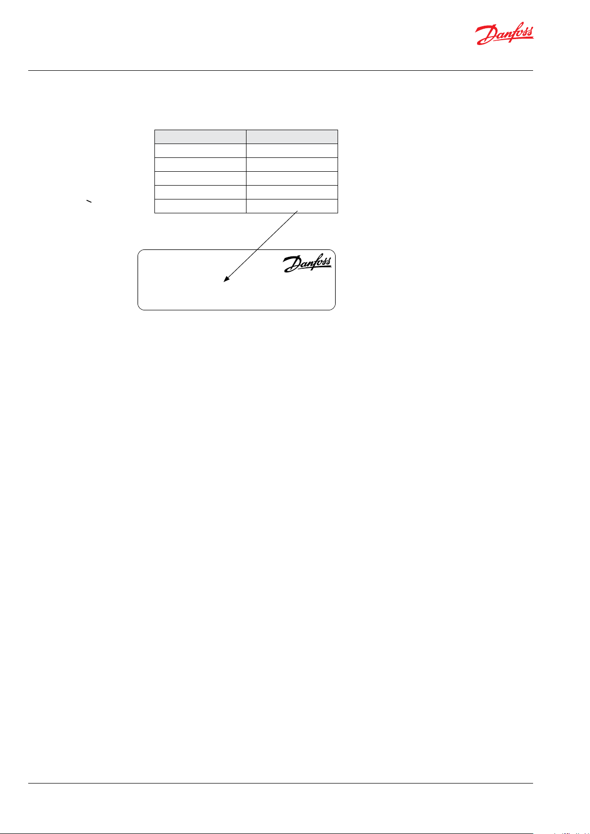
This manual is valid for APP pumps with the
following type an serial number or higher:
Typ e Serial no.
APP 53 XXXXXX08-XXX
APP 65 XXXXXX08-XXX
APP 78 XXXXXX08-XXX
APP 86 XXXXXX08-XXX
APP 92 XXXXXX08-XXX
PUMP
Type APP 78
Code no. 180BXXXX
Serial no. XXXXXX08-XXX
MADE IN DENMARK
Danfoss A/S, 6430 Nordborg, Denmark
The serial number is referring to the Serial no. on
the product label. The digits shown (08) indicate
the version number of the pump.
4 | © Danfoss | DCS (im) | 2021.12 180R9346 | IOM APP 53-92 pumps | AQ240486503020en-001701
Operation guide | Installation, Operation and Maintenance APP 53-92 pumps
© Danfoss | DCS (im) | 2021.12
1. Introduction
1.1 General
The APP pumps and pump units are manufactured by Danfoss A/S, and are sold and marketed
by a net of authorized distributors world wide.
• If any changes are made without written
approval the warranty will automatically
become void.
This manual contains the necessary instructions
for the installation, operation and service of the
pumps used in a Sea Water Reverse Osmosis
(SWRO) system or Brackish Water Reverse
Osmosis (BWRO) system.
In case the pump delivered is ATEX certified, the
additional ATEX instruction must also be read.
The APP pumps must not be used for other
purposes than those recommended and
specified without first consulting your local
pump distributor.
Use of the pump in other applications that are
not suitable for the pump unit can cause
damages to the pump unit, with risk of personal
injury.
All personnel being responsible for operation
and maintenance of the pump unit must read
and fully understand these instructions,
especially the section “Safety”, before:
It is important that these instructions are
always available to the personnel concerned.
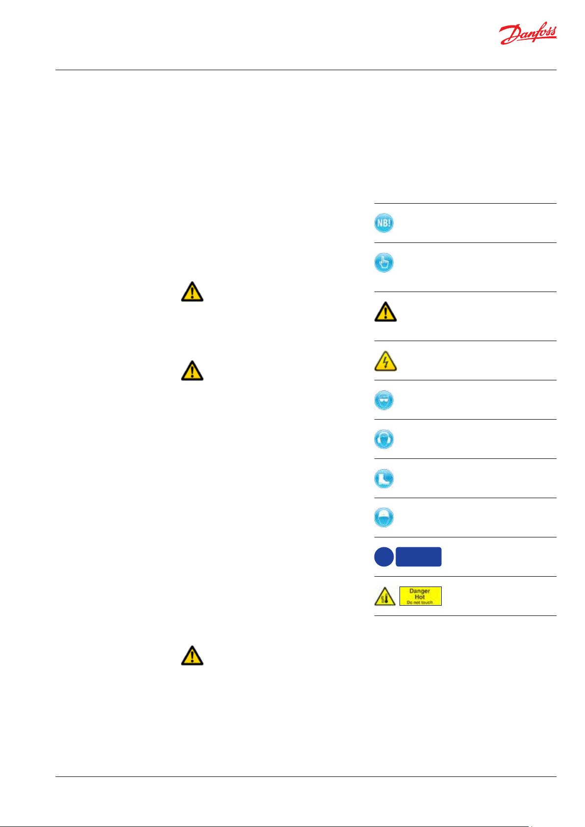
1.2 Symbols
Indicates something to be noted by the
reader
Indicates a situation which will or could
result in damage to the pump and its
function
Indicates a situation which will or could
result in personal injury and/or damage
to the pump
Electrical hazard - Indicates a highvoltage warning
Safety glasses required
• Transportation of the pump unit
• Lifting the unit
• Installing the pump unit
• Connecting the pump unit to the water
system
• Connecting the electric motor and instrumentation
• Commissioning the unit
• Servicing the pump unit, mechanical and
electrical parts
• Decommissioning the pump unit
The pump must always be installed and used in
accordance with existing national/local
sanitary, safety regulations and laws.
It is the responsibility of the safety officer or
the chief operator to assure compliance with all
local regulations that are not taken into
account in this manual.
Changing the pumps’ or pump units’ operational limits and hardware:
• Changes to the delivered pump or motor
pump unit may only be done with a written
approval from Danfoss High Pressure Pumps.
• Operation outside the Danfoss specifications
requires a written approval from Danfoss
High Pressure Pumps.
!
Hearing protection required
Safety shoes required
Safety helmet required
Protective
garments
must be wor n
Protective garments
must be worn
Danger HOT.
Do not touch
180R9346 | IOM APP 53-92 pumps | AQ240486503020en-001701 | 5
Operation guide | Installation, Operation and Maintenance APP 53-92 pumps
2. Safety
1.3 Manufacturer and customer service
address
Danfoss A/S
Danfoss High Pressure Pumps
RO Solutions
Nordborgvej 81,
DK-6430 Nordborg
Denmark
Telephone: +45 7488 4024
Fax: +45 7445 3831
Email: highpressurepumpss@danfoss.com
Homepage: hpp.danfoss.com
2.1 General information
Dangers that can arise from not following the
instructions:
When the pump or pump unit is managed by
untrained personnel, there is a danger of:
• Death or fatal injuries
• Costly damages and claims
Your local Danfoss pump distributor can be
found on our homepage.
Data sheets and instructions on all accessories
are available on hpp.danfoss.com
1.4 Country specific information
1.4.1 United Kingdom
UK importer:
Danfoss Ltd.
22 Wycombe End
HP9 1NB Beaconsfield
United Kingdom
When using an electric motor, the motor must
always be supplied with adequate cooling
ventilation.
When using an electric motor together with a
VFD, the motor must be designed for operation
with a VFD.
VFD operation may increase the temperature
inside the electric motor if the motor is not
designed for VFD operation. This can damage
the motor and cause unintended breakdown.
All electrical installation work must only be
carried out by authorized personnel in
accordance with EN60204-1 and/or local
regulations.
It is recommended to install a lockable circuit
breaker to avoid inadvertent starting and/or
electrical hazard. The lockable circuit breaker
must be used during installation, operation and
maintenance.
It is recommended to place a local safety switch
nearby the pump, enabling service personnel to
cut power for the electric motor.
Protect the motor and other electrical equipment from overloads with suitable equipment.
In case the pump delivered is ATEX certified, the
additional ATEX instruction must also be read.
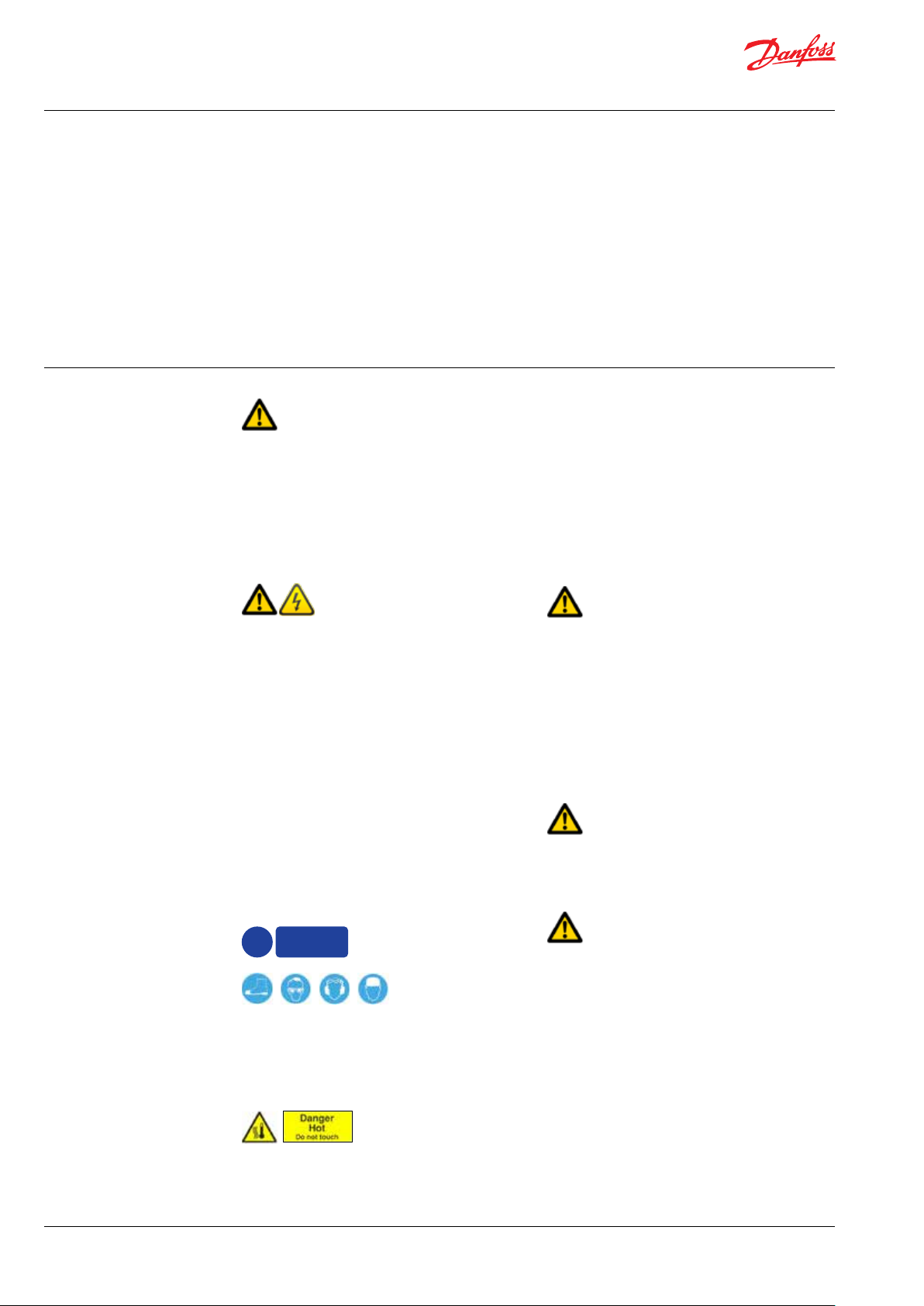
Protective
garments
!
must be wor n
Always wear suitable safety clothing when
handling the pump.
When working near the pump system, safety
shoes, safety glasses, hearing protection and
safety helmet must always be worn.
Danger
Installation and maintenance must always
take place during complete shutdown in an
unpressurised condition.
The drive unit must be secured against
switching-on (with signs, switching off electricity
power supply) in order to avoid serious injuries
due to rotating parts. Do not reach inside the
working area during the operation of the coupling.
For protection against accidental contact
appropriate security must be installed.
Before start-up, the settings for all protective
devices, such as sensors/switches and safety
valves must be verified and free flow from safety
valves must be ensured.
All pipe and hose connections must be stressfree mounted, securely fastened to the pump
and well supported. Improper installation will or
can result in personal injury and/or damage to
the pump.
Use of this manual does not relieve operation
and maintenance personnel of the responsibility of applying good judgment when operating
and maintaining the pump and its components.
inadvertent
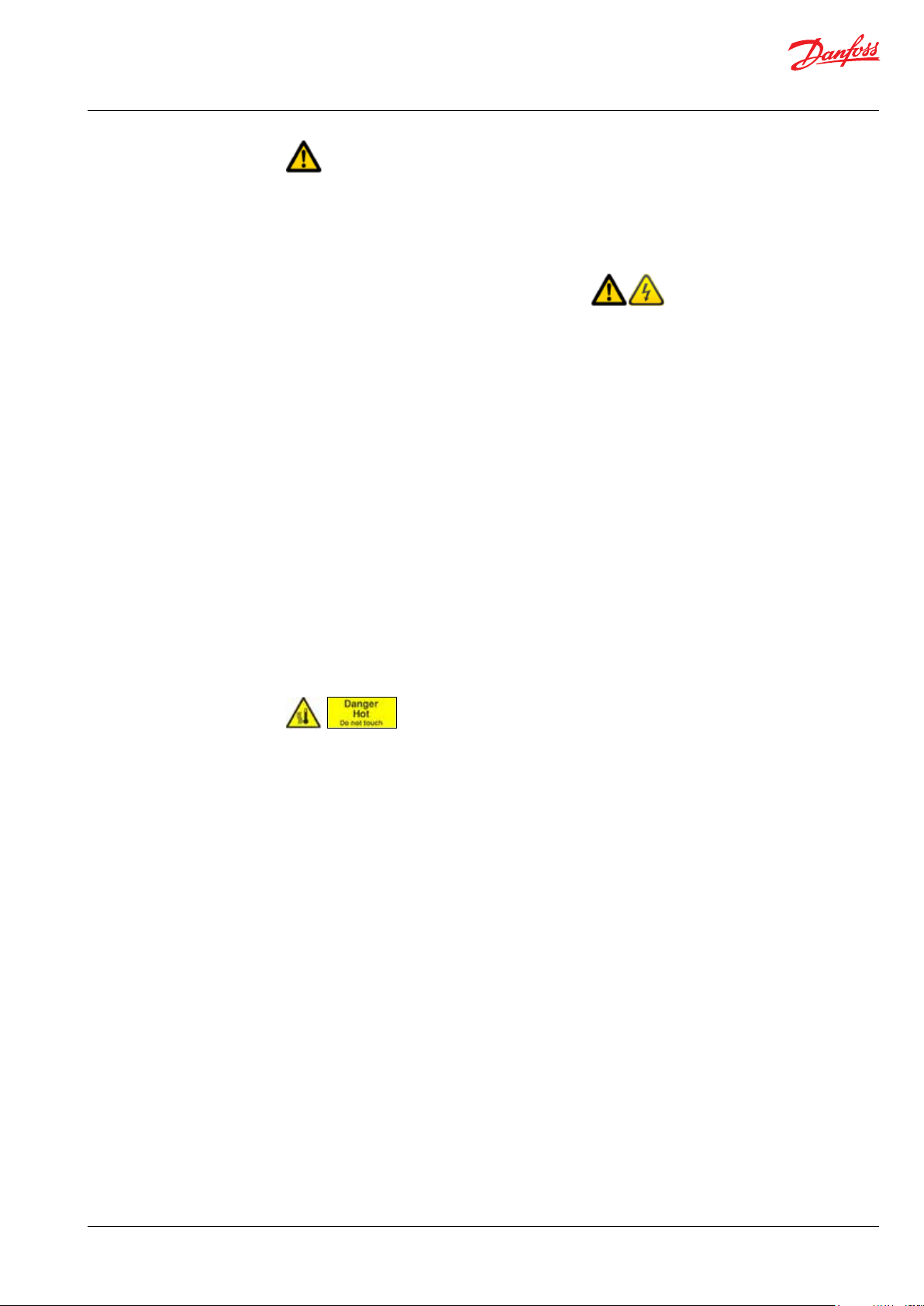
Under certain operational conditions the surface
of the pump can be above 60°C / 140°F. Under
these conditions the pump must be labelled with
a “Danger Hot” sign.
6 | © Danfoss | DCS (im) | 2021.12 180R9346 | IOM APP 53-92 pumps | AQ240486503020en-001701
2.2 Preferred system design
Danfoss recommends to build systems with a
high degree of safety. Danfoss preferred system
design and P&ID are found in appendix 1, Data
sheet, and appendix 2, Instruction.
Operation guide | Installation, Operation and Maintenance APP 53-92 pumps
© Danfoss | DCS (im) | 2021.12
It is always the system builder´s responsibility
that the system design does not cause any kind
of hazard and is adapted to local regulations and
standards.
Proper installation, proper start up and shutdown devices as well as high-pressure protection
equipment is essential.
2.3 Commissioning and servicing the unit
It is recommended that commissioning and
servicing are carried out by a minimum of two
people, where one is acting as a supervisor.
• Do not try to lift the pump unit manually;
most of the pumps weigh more than
20 kilos, see specific weight for the pump
in the appendix 1, Data sheet.
• Always bleed the pump prior to initial
start-up.
• Do not mount the pump without the bell
housing and a flexible coupling.
• Do not try to start the unit before the
system components are mounted, bleeded
and adjusted.
• Flush the system throughly before
connecting the pump or pump unit.
• Check rotation direction of the motor
before mounting the pump.
3. Technical data
2.4 Adhere to the following important
points
• Before using the pump/pump unit it is very
important to read and understand this user
manual.
3.1 Approved applications and operational
limits for the pumps
The pump and the pump units are designed for
the use in a Sea Water Reverse Osmosis (SWRO)
or Brackish Water Reverse Osmosis (BWRO)
systems.
The APP pumps must not be used for other
purposes than those recommended and
specified without first consulting your local
pump distributor.
Use of the pump in other applications not
suitable for the pump unit can cause damages
to the pump unit, with risk of personal injury.
2.5 In case of doubt
Please contact Danfoss A/S in case of doubt.
Contact information is listed in section 1.3,
Manufacturer and customer service address.
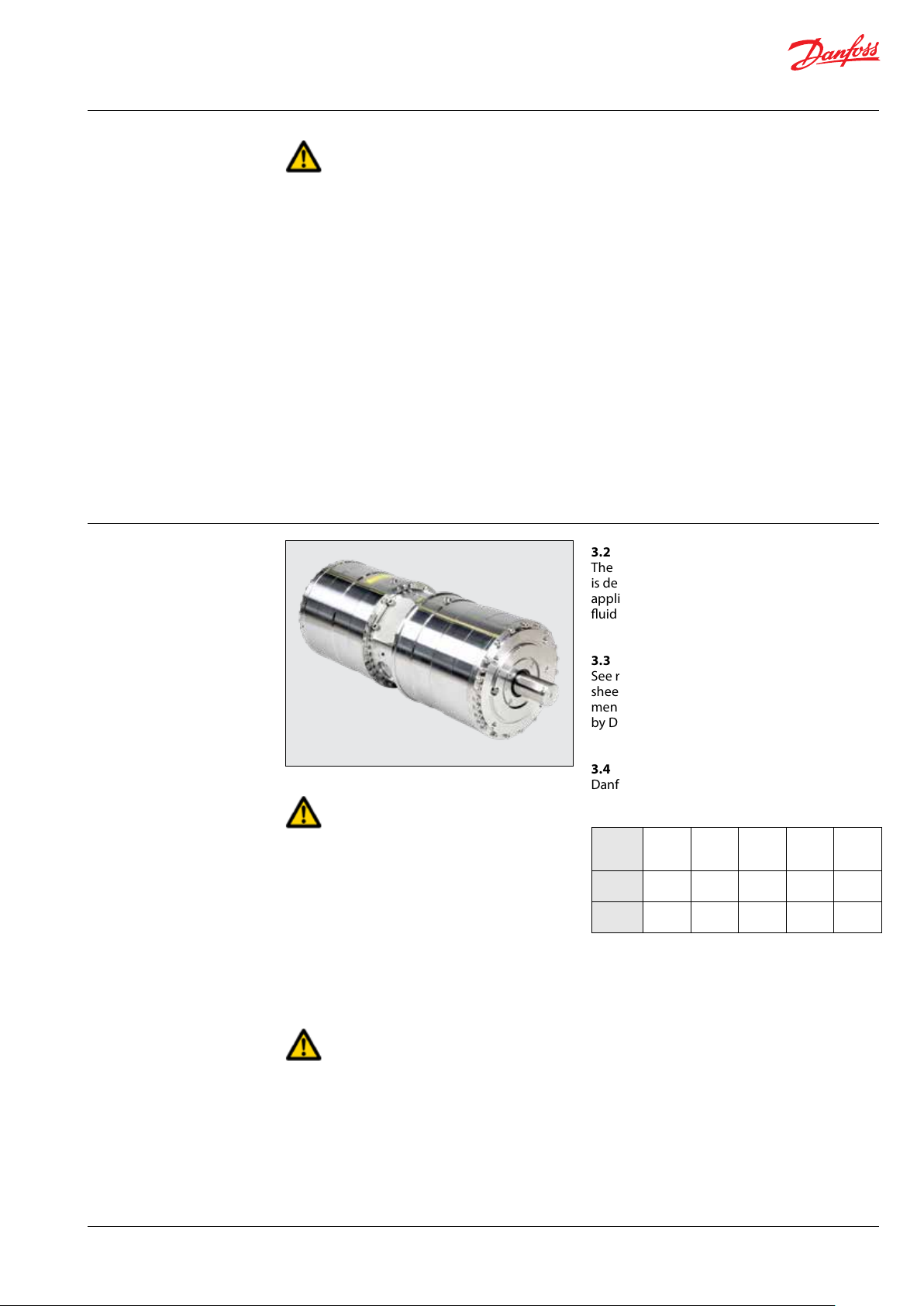
3.2 Application range
The Danfoss range of APP high-pressure pumps
is designed according to EN 809 for use in RO
applications with low viscosity and corrosive
fluids such as sea water.
3.3 Electric motor data
See recommended motor in appendix 1, Data
sheet or appendix 3, IOM for motors. The motors
mentioned are the most common used motors
by Danfoss High Pressure Pumps.
3.4 VFD and Direct on line
Danfoss APP pumps can be used with VFD and
direct on line.
Torque limits can be found in the table below:
Nm APP 53APP 65APP 78APP 86APP
92
MAWT 878 1,118 1,257 1,112 1,112
MAST 1,700 1,70 0 1,70 0 1,70 0 1,70 0
MAWT: Maximum allowable working torque
MAST: Maximum allowable starting torque
3.5 Noise and vibration
Noise level for a pump unit with a ”standard”
motor measured according to EN ISO 3744: 2010,
see appendix 1, Data sheet. Possibilities to
reduce noise and vibration are described in the
same Data sheet.
For system integration of the pump, please see
appendix 1, Data sheet and appendix 2,
Instruction.
180R9346 | IOM APP 53-92 pumps | AQ240486503020en-001701 | 7
3.6 Dimension drawings
Dimensions of the different pumps can be found
in appendix 1, Data sheet.
Operation guide | Installation, Operation and Maintenance APP 53-92 pumps
3.7 Space requirement
When doing service or replacing the complete
pump unit, it is recommended to have sufficient
space available around the pump in order to
ensure easy access. Sufficient space means at
least 1 meter/40 inches around the pump. When
working with high pressures, it is important to
have the right space available around the pump
as stated in the safety requirements.
3.8 Filtration
(10µm absolute [ß
Requirements are specified in appendix 1, Data
≥ 5000])
10
sheet and in appendix 2, Instruction.
Danfoss recommends not to build a filter bypass
function or to use filters with an integrated
bypass. If the above recommendation is not
followed the warranty for the pump will
automatically become void.
It should be possible to monitor the condition of
the filter via the differential/delta pressure across
the filter.
Using insufficient filtration or a filter bypass
can cause a failure or decreased service life of
the pump.
3.9 Properties of water
It is recommended NOT to use the pumps in feed
water concentrations higher than 50,000 ppm
TDS without consulting your local Danfoss pump
distributor.
3.10 Air bubbles
Large bubbles in a pressurised RO system can
result in damage to piping, equipment and the
pump.
All air must be bleeded from both the lowpressure and high-pressure side before the RO
system is pressurised. Special consideration
should be given in order to minimize air bubbles
in the feed flow. Air bubbles can cause cavitation.
3.11 Chemicals
The pump should not be exposed to any
chemicals as it can result in damage to piping,
equipment and internal parts in the pump.
4. Arrival inspection,
transportation,
handling, lifting and
storage
4.1 Arrival inspection
The pump is packed in a cardboard or wood box
with plugs in the port connections to protect the
pumps from damage during transportation.
When the shipment has arrived it is important to
check the pump for any damages. The name
plate/type designation must be in accordance
with the delivery note and your order.
In case of damage and/or missing parts, a report
should be documented and presented to the
carrier at once.
4.2 Warning
Before any lifting operation is performed,
environmental conditions must be taken into
consideration (Ex-rated areas, wind speed, wet/
dry conditions, lifting height, etc.).
4.3 General safety information
Personnel involved in lifting and transporting the
equipment (see Safety, chapter 2) must be
trained in handling and in safety procedures for
lifting heavy loads. Many of the pumps and
pump units weigh more than 20 kilos, which
requires lifting slings and suitable lifting devices;
e.g. an overhead crane or industrial truck to be
used as minimum.
4.4 Transport and handling
Small pumps which have a weight below 20 kilos
can be handled by hand if they are not mounted
together with an electric motor. The weight of a
small pump with a motor will be above 20 kilos.
Do not use connections/nozzles for lifting!
Do not use only one sling!
8 | © Danfoss | DCS (im) | 2021.12 180R9346 | IOM APP 53-92 pumps | AQ240486503020en-001701
Operation guide | Installation, Operation and Maintenance APP 53-92 pumps
© Danfoss | DCS (im) | 2021.12
Pumps which have a weight above 20 kilos must
be handled by using lifting eyes and slings.
Wrong lifting:
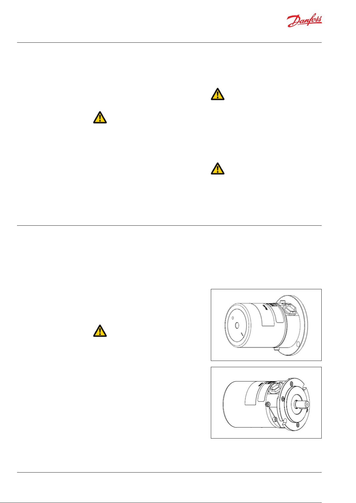
When the pump is mounted together with a bell
housing, the pump can be rotated and in that
case the lifting eye cannot be used in all
positions. When lifting a pump with bell housing,
a sling can be used to lift the pump by positioning it on the drive end of the pump outlet.
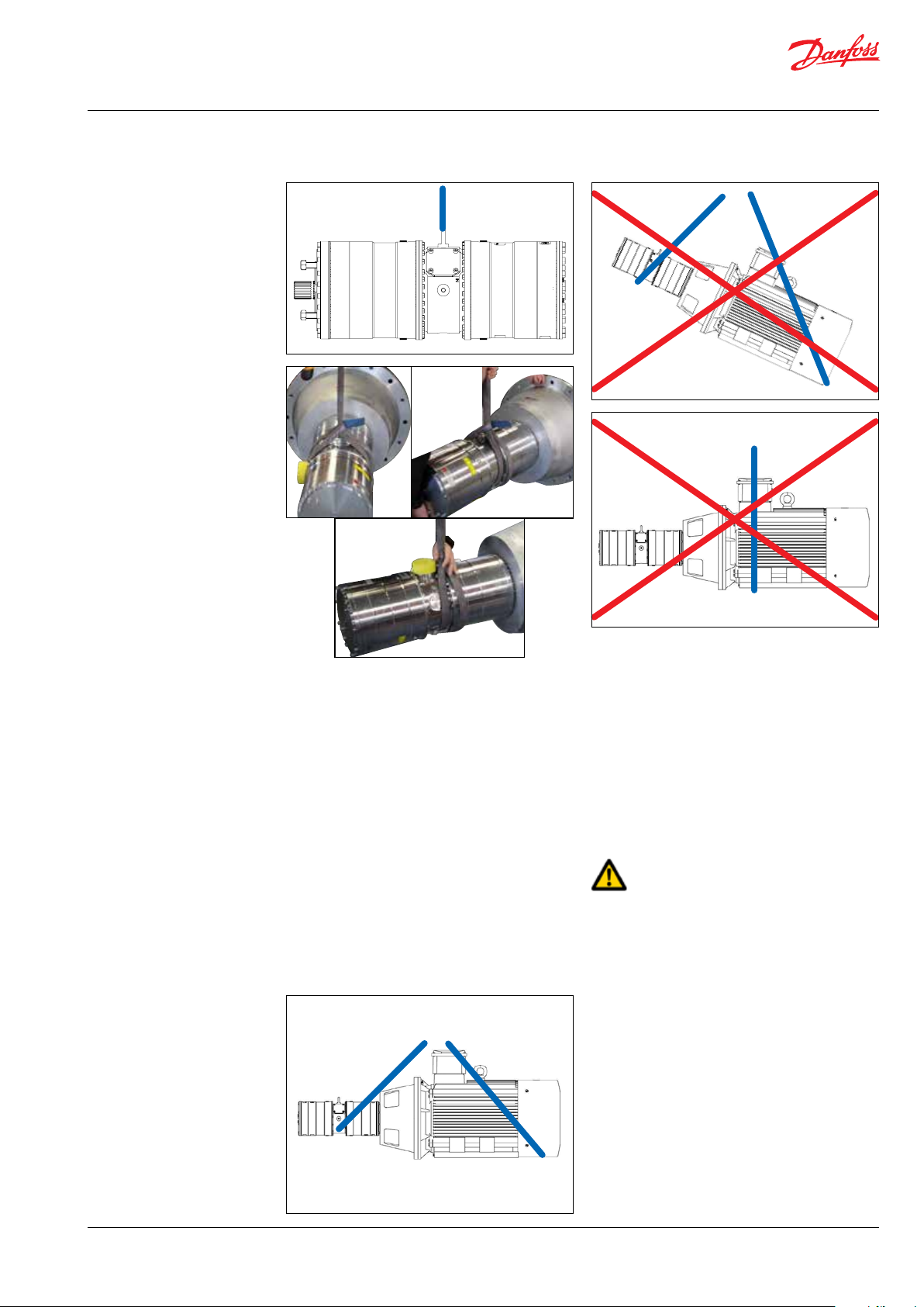
When the pump is mounted together with an
electric motor, it must not be lifted in the lifting
eye. A pump unit with motor must be handled by
using two slings around the pump unit. One sling
must be attached to the electric motor and one
sling around the pump.
Make sure that the unit/load is balanced before
lifting. The centre of the mass varies from pump/
pump unit size to pump(pump unit).
See below examples of where to/not to attach
the lifting slings on the pump unit with motor:
Correct lifting with 2 separate slings:
Some motors and pumps have specific lifting
eyes.
Do not use connections/nozzles for lifting!
Do not use only one sling!
Make sure that the unit/load is balanced before
lifting. The centre of the mass varies from pump/
pump unit size to pump/pump unit.
How to mount the pump and the electric motor
correctly, see appendix 1, Data sheet or appendix
2, Instruction.
Incorrect lifting can result in personal injury
and/or damage to the pump unit, see appendix
2, Instruction.
Once the lifting is done the lifting eye must
be removed from the pump.
4.5 Return to supplier
Please see maintenance chapter 7.
4.6 Storage
Each pump is tested before shipment, and will
therefore contain water. For storage temperature
and frost protection see appendix 2, Instruction.
The pumps are NOT delivered frost protected
from the factory.
180R9346 | IOM APP 53-92 pumps | AQ240486503020en-001701 | 9
Operation guide | Installation, Operation and Maintenance APP 53-92 pumps
5. Installation and
commissioning
5.1 Important dimensions
Physical dimensions and connections of the
pump unit are described in appendix 1, Data
sheet.
5.4 Electrical data
Check voltage, current frequency and rated
power on the electric motor and VFD settings on
the name plate placed on both the motor and
the VFD.
5.2 Cleanliness
It is very important that the tubes and pipes are
completely clean: no dirt, chips or burrs are
allowed. Flush all piping before connecting the
high-pressure pump to ensure the system is
clean. Internal surfaces of the piping must not be
corroded. If dirt or rust is not removed, the pump
and the valves can be damaged. In worst case
the pump can be damaged beyond repair!
5.3 Fluid temperature
Before start-up, the fluid and pump housing
temperature must be within the specified
temperature range listed see appendix 1, Data
sheet.
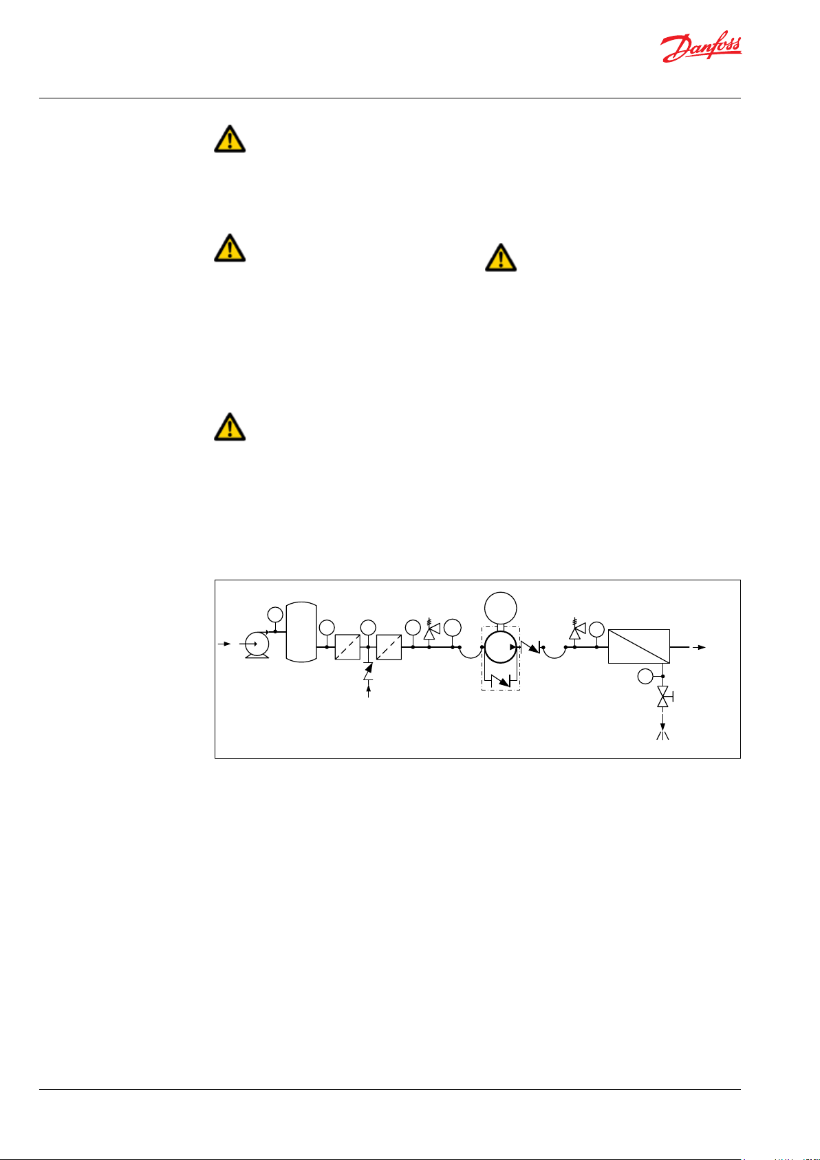
Schematic 1: Recommended system design
Media filter
Feed
PI
PI
PI PI
PT
5.5 Local regulations
Commissioning must always be done in
accordance with valid regulations and local
standards.
M
PI
Permeate
Fresh water
permeat flush
PI
Brine
10 | © Danfoss | DCS (im) | 2021.12 180R9346 | IOM APP 53-92 pumps | AQ240486503020en-001701
Operation guide | Installation, Operation and Maintenance APP 53-92 pumps
© Danfoss | DCS (im) | 2021.12
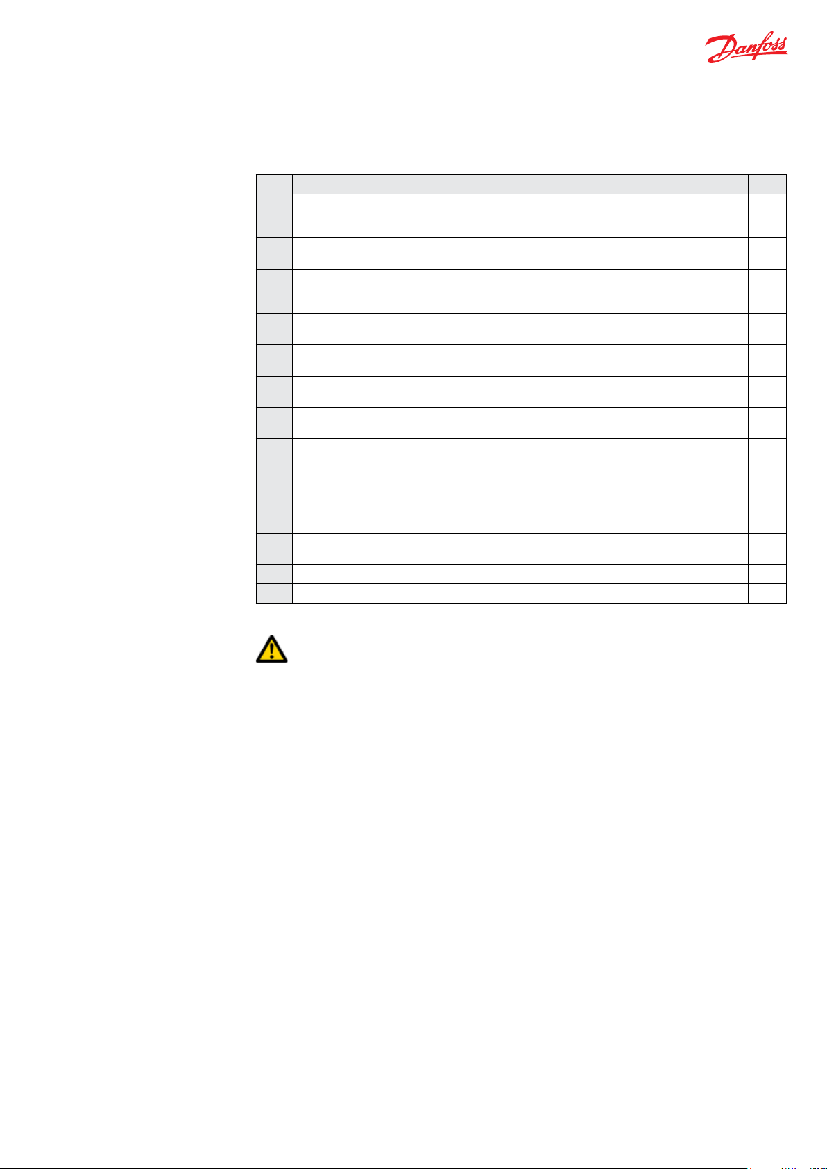
5.6 Pre mounting checklist, based on Danfoss preferred system design
Table 1: Check points when assembling and commissioning system
Check points Comment OK ?
Ensure that the environmental conditions are safe. See Arrival inspection,
CP1
Minimum and maximum start-up temperature for fluid and
CP2
pump.
Filtration condition (10 µm absolute (ß
CP3
Power supply for electric motor and VFD. See Data sheet for the used
CP4
Safety circuit / breaker must be sized for the motor and
CP5
environment (corrosion and humidity)
Bolts and screws must conform to environmental conditions
CP6
as well as fluid and torque requirements.
Instrumentation, pressure switch should be designed to
CP7
conform to the environment (corrosion and humidity).
Check the factory settings of the safety/relief valves or
CP8
pressure relief valves (page 11).
Check the settings of the pressure transmitter/switch (3) set
CP9
at min. inlet pressure (page 11).
Check that all pressure indicators (PI) are selected to be able
CP10
to measure the system pressure range (page 11).
Check that the coupling is installed according to manufac-
CP 11
turers instruction
Ensure all pipings have been flushed and are correct installed
CP12
Check piping for possible air gaps.
CP13
transportation, handling,
lifting and storage, chapter 4.
See Data sheet or Instruction,
appendices 1 and 2.
≥ 5000) See Danfoss requirements in
10
Data sheet and Instruction,
appendices 1 and 2
motor and VFD.
See Data sheet for the used
safety circuit.
See Data sheet for the used
equipment.
See Data sheets for the used
valves.
See Data sheet or Instruction,
appendices 1 and 2.
Scaling should at least be 1 bar
or more precise.
5.7 Lifting and positioning
Lift the pump unit onto base (Remember
vibration dampeners, if needed). Fasten the
motor to the base.
See also chapter 4, Arrival inspection, transportation, handling, lifting and storage.
5.8 Mount the different equipment
(connections, pipes, tubes, check and safety/relief
valves, etc.)
• The hard piping and flexible hoses used,
must be of proper design and must be
installed in accordance with the manufacturer’s recommendations. (see also Design
guides 180R9084 and 180R9367 - both
available on hpp.danfoss.com).
• Misalignment of the hard pipes may give
unintended stress on the pump port
connections and may damage the pump.
• Prevent excessive external pipe load.
• Do not connect piping by applying external
force (use of wrenches, crane, etc.) Piping
must be aligned without residual stress.
• Do not mount expansion joints so that their
force applies internal pressure on the pump
connections.
5.9 Electrics
All electrical installation work must be carried
out by authorized personnel in accordance with
EN60204-1 and/or local regulations. (see also
Safety, chapter 2)
Turn off the safety circuit breaker and lock it.
Mount the power cable on the electric motor.
If a VFD is used, adjust the protective motor
switch/VFD to the current limits found on the
name plate of the electric motor.
5.10 Instrumentation
The pressure switch/sensor should be mounted
as close to the pump as possible. It is recommended to test the pressure/sensor switch via an
instrumentation manifold.
Mount the pressure switch/sensors according to
the manufacturer’s instructions.
180R9346 | IOM APP 53-92 pumps | AQ240486503020en-001701 | 11
Operation guide | Installation, Operation and Maintenance APP 53-92 pumps
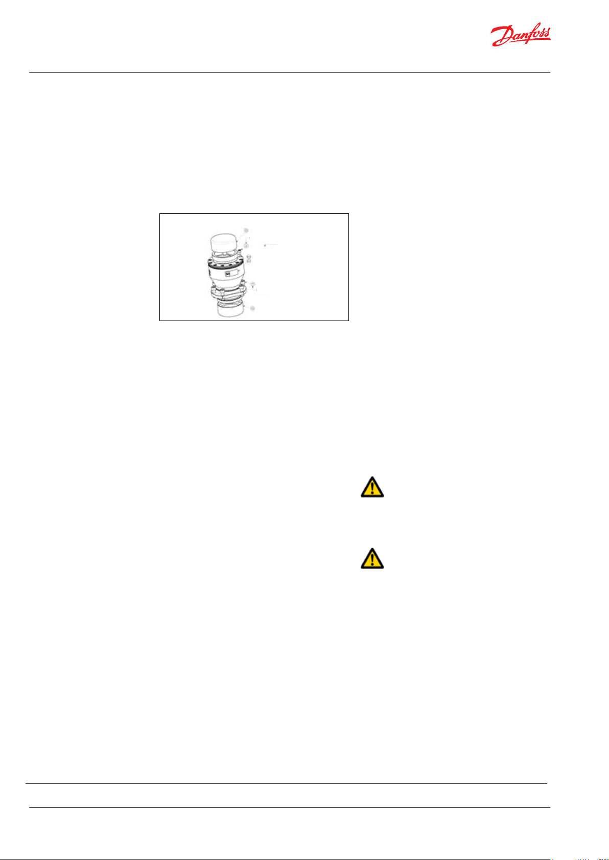
5.11 Connections
Mount and tighten connections and check
valve(s) as specified.
Danfoss check valve VCM 92 comes with a flange
connection that is easily mounted directly on the
outlet port (outlet connection is not required).
Note: Bolts (ref. 11) must be tightened with
torque 95Nm ± 9.5 Nm.
Use only Style 77DX coupling or equivalent for
the 3” victaulic OSG outlet on the VCM 92.
95 Nm ± 9.5 Nm
5.12 Ensure free flow
Ensure free flow from the safety/relief valves 8
and 9 (schematic1, page 10). A blocked safety/
relief valve can cause excessive build-up of
pressure and thereby cause dangerous situations
and damage to the whole system.
5.13 Verify setting of safety/relief valves
Make sure, the safety/relief valves 8 and 9 are
placed correctly.
Check the pressure settings on the name plates
of the safety/relief valves. If they are within
specifications, you can continue.
Unlock the safety circuit breaker. Start the motor
for 1 second and observe the direction of
rotation either looking at the fan of the motor or
the coupling through the inspection hole in the
bell housings (not available on all bell housings).
If the motor is turning the wrong direction,
switch two phases in the connection box of the
motor or reprogram the direction in VFD.
When the motor is turning in the right direction,
the pump can be mounted.
5.17 Commissioning
• Close all the bleeding and draining plugs.
• Open the pressure valve at the brine site.
• Switch the safety circuit breaker on for both
motor(s) and VFD(s).
• Start the feed pump.
• Start the high-pressure pump.
• If a VFD or a soft starter is used, a ramp up
time of minimum 10 seconds is required to
avoid damage of the pump.
• Monitor the inlet and outlet pressure of the
high-pressure pump and look for leakages.
• Check the function of the pressure
indicators by slowly closing the valves. The
pump unit should stop when the minimum
inlet pressure and maximum outlet
pressure has been reached.
• Adjust the pressures to the specified inlet
and outlet pressure for the system and let
the pump unit run until the electric motor
and pump temperature is stable.
• If the system is running within the system
design limits, the system is released for
operation.
5.14 Flush the pump
Fully open the pressure valve at the brine outlet.
Close all the bleeding and draining plugs on the
high-pressure pump.
Start the feed pump and ensure free flow to the
high-pressure pump.
5.15 Bleed and remove air from the pump
Open the bleeding plugs. Keep the plugs open
until the high-pressure pump is bleeded.
5.16 Verify direction of rotation
The direction of rotation must always follow the
arrow. The arrow is placed on the pump or pump
unit.
Check the direction of rotation before mounting
the pump.
5.18 Check the filter condition
Evaluate contamination found in filter, replace
filter elements, if necessary.
5.19 Instruct operator and maintenance
personnel
Before using the pump/pump unit, the personnel
must be instructed in using the pump/pump
unit, its function, components, documentation
and safety.
Danfoss offers commissioning and service at
system manufacturer’s location. Rate quotes are
offered upon request.
12 | © Danfoss | DCS (im) | 2021.12 180R9346 | IOM APP 53-92 pumps | AQ240486503020en-001701

Operation guide | Installation, Operation and Maintenance APP 53-92 pumps
© Danfoss | DCS (im) | 2021.12
6. Operation of pump
unit
6.1 General safety information
Before inspecting the pump unit, read the Safety
chapter 2 in this user manual.
6.2 What to listen and look for
If one or more of the following examples are
observed, please act as indicated:
A) Loose bolts – check all bolts and, if
necessary, contact the maintenance
department in order to have all bolts
tightened to the specified torque(s).
B) Leakage – if a small leakage from the bell
housing is observed. Contact the maintenance department.
C) Leakage – if there is a large leak, the unit
should be stopped immediately. Contact
the maintenance department.
D) High frequency tones – safety/relief valves
are either damaged or running very close
to their design pressure, stop the unit
immediately. Contact the maintenance
department.
E) Increased noise or vibration – requires the
unit to be stopped immediately. Contact
the maintenance department.
F) Very high temperatures – may indicate that
one or more parts are damaged inside the
pump. The pump must be stopped
immediately and inspected before it is
restarted. Contact the maintenance
department.
G) Drop in flow and/or pressure – may indicate
wear on one or more parts inside the
pump. The pump must be stopped
immediately and inspected before it is
restarted. Contact the maintenance
department.
H) Other observations or troubles, please see
appendix 7, Right and Wrong or appendix
6, the Trouble shooting guide.
Both appendices give good advises
regarding design, installation, wiring and
troubleshooting.
See also service and warranty section in
appendix 1, Data sheet and appendix 2,
Instruction.
If the pump is not stopped for inspection as
recommended, it can lead to damage of the
pump or break-down. See also service and
warranty section in the appendix 1, Data sheet,
in appendix 2, Instruction or appendix 4,
Instruction for recommended service intervals.
Danfoss offers service of the pump at the system
manufacturer’s location as well as we offer
training in how to service the pump. Quotes are
offered upon request.
Danfoss recommends simultaneously to check
the filter and membrane condition and to
evaluate contamination; filter and membrane
elements must be replaced if necessary.
7. Maintenance and
service of the pump
unit
7.1 General safety information
Before servicing the pump unit, it is necessary to
read and understand this user manual, especially
the Safety, chapter 2. Remember to wear suitable
safety equipment according to Safety, chapter 2.
7.2 Service and inspection interval for the
pump
Maintenance and service intervals are depending
on the cleanliness level of the water, hydraulic
load and temperature of the pump unit. The
most important parameter is the filtration of the
water.
See the section Service and warranty in the
appendix 1, Data sheet, in appendix 2, Instruction and appendix 4, Instruction for recommended service intervals.
For spare parts and service tools, please see
appendix 5, Parts list.
180R9346 | IOM APP 53-92 pumps | AQ240486503020en-001701 | 13
Danfoss offers service of the pump at the system
manufacturer’s location and training in how to
service the pump. Quotes are offered upon
request.
7.3 Shut down of the system
A) Stop the high-pressure pump.
B) Open the pressure valves at the brine site
to release the pressure.
C) Stop the feed pump.
D) Switch off the safety circuit breaker for
both the high-pressure pump, feed pump
and VFD and lock them. Only personnel
servicing the pump unit should be able to
unlock/activate the switch again.
E) Open bleeding and drain plugs. Wait until
the pump and system are emptied for
water.
Operation guide | Installation, Operation and Maintenance APP 53-92 pumps
F) Make sure the system is not pressuized!
Slowly unscrew and remove the bolts and
gaskets from the inlet/outlet hoses or
pipes, be careful about jets of water.
Beware that the system can be pressurized!
G) Attach the lifting equipment to the pump
unit. For instructions on lifting the
complete pump unit, see chapter 4, Arrival
inspection, transportation, handling, lifting
and storage.
H) For the small pumps, unscrew the bolts
holding the pump to the bell housing. For
the bigger pumps, unscrew the bolts/nuts
from the pump and bell housing to the
motor. Afterwards unscrew the bolts/nuts
holding the pump and bell housing.
I) Carefully pull the pump out of the bell
housing by using lifting equipment, if
necessar y.
J) Hold the pump in different positions above
a drip tray; this should allow most of the
water trapped in the pump to drain. Clean
and dry the pump surface and plug the
bleeding and draining plugs.
K) Move the pump to a clean and safe location
where the pump can be inspected/
serviced.
7.4 Disassembling and assembling the
pump unit
A) Remove all connections from the pump.
Returns without a return number will be
rejected !!!
7.5 Assembling the pump unit
Assemble the pump according to the Disassembling and Assembling Instruction
(available at hpp.danfoss.com).
7.6 Procedure for mounting the pump onto
the electric motor
Mount the flexible coupling and bell housing
according to appendix 2, Instruction.
7.7 Getting the pump unit back into
operation
Find instructions of how to put the pump unit
back into operation in chapter 4, Arrival inspection, transportation, handling, lifting and storage
and Installation and commissioning, chapter 5.
B) Disassemble the pump according to the
Disassembling and Assembling Instruction
(available at hpp.danfoss.com)
Clean all parts and surfaces with a fluid
compatible with the materials found in the
pump. Wipe the parts clean and dry with a
lint-free clothing.
C) Inspect all parts including shaft seal and if
necessary, replace them; see appendix 5,
Parts list.
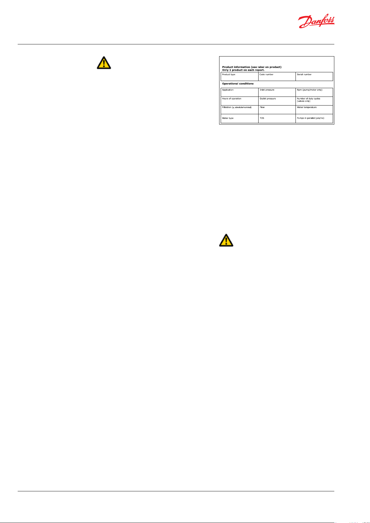
D) If the pump is going to be returned to
Danfoss for repair or a warranty claim, it is
important to contact Danfoss in order to
receive a return number and a form to fill
out with product information. A copy of the
form together with contact information
and reason for returning should be sent to
the email address on the form. The same
documents should be attached to the
shipment.
14 | © Danfoss | DCS (im) | 2021.12 180R9346 | IOM APP 53-92 pumps | AQ240486503020en-001701
7.8 Storage of the pump
If the pump has to be shut down for a longer
period, instructions can be found in appendix 2,
Instruction.
Operation guide | Installation, Operation and Maintenance APP 53-92 pumps
© Danfoss | DCS (im) | 2021.12
8. Troubleshooting and
scrapping criteria
8.1 General safety information
Before inspecting the pump unit, it is necessary
to read and understand this user manual,
especially the Safety chapter 2.
Remember to wear suitable safety equipment
according to Safety chapter 2.
If water is leaking into the electric motor; it can
cause electric shock, fire, short circuit or even
death. When mounting the pump vertically
always mount the motor above the pump to
avoid water leaking into the electric motor.
8.2 Operational conditions which can cause
pump failures
The following conditions can cause a pump
failure :
• The pump is running dry.
• The inlet pressure is too high.
• The inlet pressure is too low.
• The temperature of the fluid is too high.
• The ambient temperature is too high.
• The pump is running against a blocked
port/closed manual valve.
• The pump is operating at a pressure out of
specification.
• The pump is running with a non-specified/
approved fluid.
• The pump is running in the wrong
direction.
• The filtration is insufficient.
• The pump is not being serviced according
to Danfoss specifications (end of life).
• There is excessive mechanical load on the
shaft coupling and piping.
8.3 Mechanical failure
If the pump is running dry, the temperature will
quickly increase which can cause burns.
If there is any leakage at start-up or during
operation, a high-pressure jet can cause eye or
skin damage.
Leakage can result in flooding, which can cause
slipping, tripping or falling.
8.4 Electrical failure
If the wiring of the electric motor is incorrect or
the ground connection is missing, it can cause
electric shock, burn damages, fire or even death.
If a VFD is used and wrongly programmed, it can
damage the pump and lead to high temperatures or other dangers.
All electrical installation must be carried out by
authorized personnel in accordance with
EN60204-1 and/or local regulations.
8.5 Responsibility
Danfoss takes no responsibility for any abnormal
injuries, risks or damages that could arise caused
by abnormal conditions, vibrations, corrosion,
abrasives, foreign objects or excessive temperatures and shall not be liable for any consequential or incidental damages.
8.6 Scrapping criteria
Whether the pump can be repaired or need to be
scrapped, depends on in which conditions the
internal parts are, or how damaged the whole
unit is. Please use appendix 6, Trouble shooting
guide as guideline or send the pump to Danfoss
headquarter in Denmark for evaluation.
For other observations or troubles, please see
appendix 7, Right and Wrong which gives good
advises regarding design, installation, wiring and
troubleshooting.
In case the pump needs to be scrapped, please
follow your local environmental rules.
180R9346 | IOM APP 53-92 pumps | AQ240486503020en-001701 | 15

Operation guide | Installation, Operation and Maintenance APP 53-92 pumps
16 | © Danfoss | DCS (im) | 2021.12 180R9346 | IOM APP 53-92 pumps | AQ240486503020en-001701
Operation guide
APP pumps
APP 53 / APP 65 / APP 78 / APP 86 / APP 92
Appendices for Installation, Operation
and Maintenance Manual
hpp.danfoss.com

Operation guide | Installation, Operation and Maintenance APP 53-92 pumps
Table of Contents
Appendices .......................................................................................17
1. Data sheet for APP pumps 53-92 AI167386503010en-0013
2. Instruction for APP pumps 53-92 (180R9368) ............................................43
3. Electric motors (180R9230) ..............................................................55
4. Bowex coupling manual .................................................................61
5. Recommended service intervals (AX281930801330en-000401) ..........................85
6. Parts list (AX191786502906en-001101) ...................................................89
7. Trouble shooting (521B1447) ...........................................................101
8. Right and wrong (180R9042) ..........................................................113
01) ...........................19
18 | © Danfoss | DCS (im) | 2021.12 180R9346 | IOM APP 53-92 pumps | AQ240486503020en-001701
Data sheet
Data sheet
APP Pumps
APP pumps
APP 53 / APP 65 / APP 78 / APP 86 / APP 92
APP 53-86
hpp.danfoss.com
ro-solutions.com

Data sheet | APP 53-92 Pumps
Table of Contents
1. Introduction ...........................................................................21
2. Benefits................................................................................21
3. Application examples ..................................................................21
4 Technical data .........................................................................22
4.1 APP 53-92..............................................................................22
5. Performance curves....................................................................24
5.1 APP 53 flow at different rpm............................................................24
5.2 APP 65 flow at different rpm............................................................25
5.3 APP 78 flow at different rpm............................................................26
5.3 APP 86 flow at different rpm............................................................27
5.4 APP 92 flow at different rpm............................................................28
6. Flushing valve curves ..................................................................29
6.1 APP 53-92 integrated flushing valve ....................................................29
7. Motor requirements....................................................................29
7.1 Calculation factor at 60 barg / 870 psig for APP 53-92 ...................................29
8. Temperature and corrosion.............................................................30
8.1 Operation..............................................................................30
9. Installation.............................................................................30
9.1 Filtration...............................................................................31
9.2 RO system with direct supply: ..........................................................31
10. Dimensions and connections...........................................................33
10.1 APP 53.................................................................................33
10.2 APP 65 - 92.............................................................................34
10.3 APP 53-92 with IE3 motor, IEC 315S - 4 ..................................................36
10.4 APP 53-92 with IE3 motor, IEC 315M - 4..................................................36
10.5 APP 53-92 with IE3 motor, IEC 315L 1-4 .................................................37
10.6 APP 53-92 with IE3 motor, IEC 315L 2 - 4 ................................................37
11. Pump connections .....................................................................38
11.1 APP 53 - 92.............................................................................38
12. VCM 3” Victaulic........................................................................39
12.1 Technical data .........................................................................39
12.2 Flow versus pressure ...................................................................40
13. Accessories ............................................................................41
14. Service and warranty...................................................................41
20 | © Danfoss | DCS (im) | 2021.12
180R9346 | IOM APP 53-92 pumps | AQ240486503020en-001701
Data sheet | APP 53-92 Pumps
1. Introduction
The Danfoss range of APP high-pressure pumps
is designed according to EN 809 for use in RO
applications with low viscosity and corrosive
fluids such as sea water.
Danfoss APP pumps are positive displacement
pumps with axial pistons that move a fixed
amount of water in each cycle. Flow is proportional to the number of input shaft revolutions
(rpm).
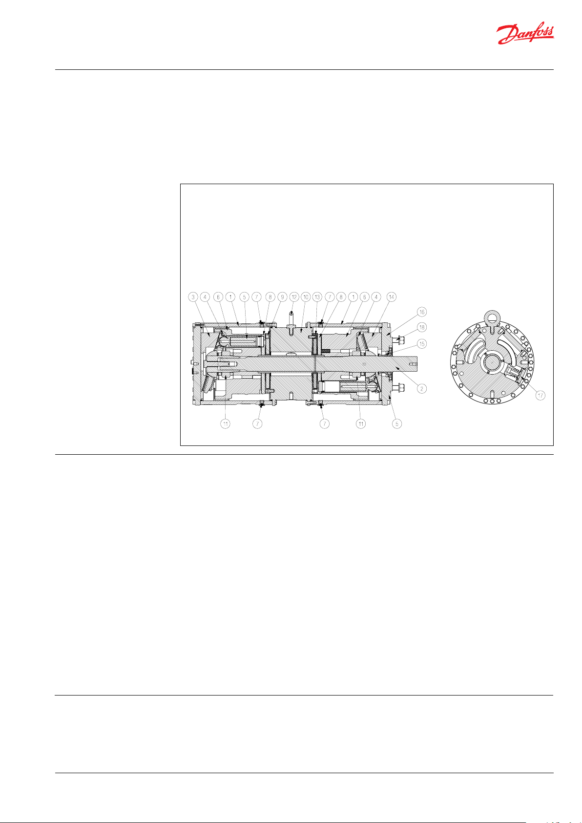
1 Housing
2 Shaft
3 Swash plate (non drive end)
4 Retainer plate
5 Piston
6 Cylinder barrel
7 Bleeding / drain plug
8 Valve plate
9 Port plate (non drive end)
Unlike centrifugal pumps, they produce the same
flow at a given speed no matter what the
discharge pressure.
The sectional drawing below illustrates the main
components of the APP 53-92 pump range.
10 Center flange
11 Spring cartridge
12 Eye bolt
13 Port plate (drive end)
14 Swash plate (drive end)
15 Shaft seal
16 Motor flange
17 Flushing valve
18 Tail stock screws
2. Benefits
3. Application examples Danfoss APP pumps are built into a broad range
• Zero risk of lubricant contamination:
- Oil lubricants are replaced with the
pumped medium, water, so there is no
contamination risk from the pump.
• Low maintenance costs:
- Efficient design and all-stainless steel
construction ensure exceptionally long
life. When Danfoss specifications are
met, service intervals of 8,000 hours can
be expected. Service is easy, and can be
carried out on-site due to the simple
design and few parts.
• Low energy costs:
- The highly efficient axial piston design
provides the lowest energy
consumption of any comparable pump
on the market.
• Easy installation:
- The most compact and lightest design
available.
- The pump can be installed horizon-
tally in different positions rotating it
around the shaft (see section 10 for
example).
of RO desalination plants around the world:
• Containerized solutions for hotels, resorts
and residences on islands and in coastal
regions
No pulsation dampeners necessary due
to extremely low pressure pulsation.
- Powered directly by electric motors or
combustion engines (with special
coupling).
- All pumps are supplied with an
integrated flushing valve that allows the
fluid to flow from inlet to the outlet,
when the pump is not running.
• High reliability:
- All parts are made of high corrosion
resistant materials e.g. Duplex
(EN1.4462/ UNS S31803) and
Super Duplex (EN1.4410/UNS S32750)
stainless steel and carbon reinforced
PEEK.
• Certified quality:
- Available with positive material
idenfication (PMI) certification on
request.
- ISO 9001, ISO 14001, IAFT 16949
- ATEX certification available for APP S (all
Super Duplex) and APP S 674 (API).
Please see relevant data sheets.
• Mobile systems for humanitarian and
military organizations
• Onboard systems for ships and yachts
• Offshore platforms for the oil and gas
industry
• Municipal and regional waterworks
© Danfoss | DCS (im) | 2021.12
180R9346 | IOM APP 53-92 pumps | AQ240486503020en-001701 | 21
Data sheet | APP 53-92 Pumps
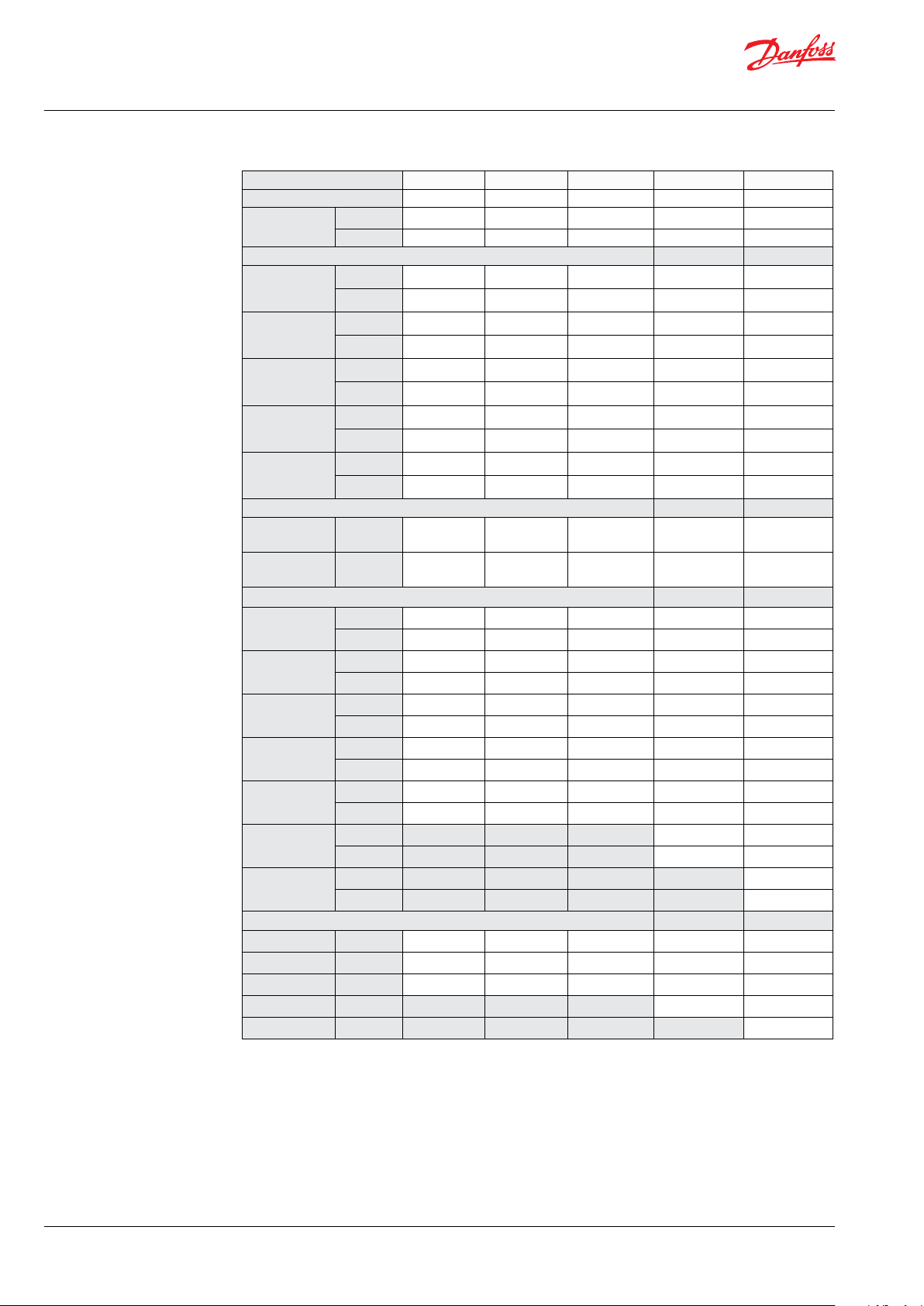
4.1 APP 53-924 Technical data
Pump size APP 53/1500 APP 65/1500 APP78 /1500 A PP 8 6/1700 APP 92 /178 0
Code number 180B7806 180B7807 180B7808 180B7809 180B7810
Geometric
displacement
Pressure
Max. outlet
pressure
(MAWP)
Min. inlet
operating
pressure
Max. inlet
operating
pressure
Max. inlet
pressure peak
Min. outlet
pressure
Speed
Min. speed
continuous
Max. speed
continuous
Flow
Min. flow
700 rpm at
max. pressure
1000 rpm at
max. pressure
1200 rpm at
max. pressure
1500 rpm at
max. pressure
1700 rpm at
max. pressure
1780 rpm at
max. pressure
Efficiency
1000 rpm
1200 rpm
1500 rpm
170 0 rp m
178 0 rp m
cm³/rev. 617 778 888 888 888
in³/rev. 37. 7 47. 3 54.2 54.2 54.2
1)
barg 83 83 83 70 70
psig 1,200 1,200 1,200 1,015 1,015
barg 2 2 2 2.5 3.5
psig 29 29 29 36 50
barg 5 5 5 5 5
psig 73 73 73 73 73
barg 10 10 10 10 10
psig 145 145 145 145 145
barg 30 30 30 30 30
psig 435 435 435 435 435
rpm 700 700 700 700 700
rpm 1,500 1,500 1, 500 1,700 1,780
m³/h 24 32 36 36 36
gpm 106 141 158 158 15 8
m³/h 24 32 36 36 36
gpm 106 141 158 158 15 8
m³/h 35 45 52 52 52
gpm 15 4 198 228 228 228
m³/h 42 54 62 62 62
gpm 187 238 275 275 275
m³/h 53 68 78 78 78
gpm 235 299 345 345 345
m³/h 88 88
gpm 387 387
m³/h 92
gpm 405
3)
% 88 88 89 89 89
3)
% 89 89 90 89 89
3)
% 88 89 89 88 88
3)
% 88 88
3)
% 87
22 | © Danfoss | DCS (im) | 2021.12
180R9346 | IOM APP 53-92 pumps | AQ240486503020en-001701
Data sheet | APP 53-92 Pumps
Pump size APP 53/150 0 APP 65/15 00 APP 78/1500 APP 86/1700 APP 92 /1780
Code number 180B7806 180B7807 180B7808 180B7809 18 0B7810
Technical specifications
2)
Media
temperature
Ambient
temperature
Weight (dry)
Weight
(operation)
°C 2–50 2-50 2–50 2-50 2-50
°F 36–122 36-122 3 6–122 36-122 36-12 2
°C 0–50 0-50 0–50 0-50 0-50
°F 32–122 32-12 2 32–122 32-12 2 32-122
kg 196 196 196 19 6 196
lb 432 432 432 432 432
kg 204 204 204 204 204
6)
lb 450 450 450 450 450
Sound
pressure level
Footprint with
IE3 motor
db(A) 84-95 84-95 84-93 84-96 84-96
m² 1.49 1.49 1. 50 1.50 1.50
4)
Foot² 16.0 17. 0 16.1 16.1 16.1
Typical motor size
Max.speed at
max. pres-
5)
sure
1)
Max. allowable working pressure at continuous operation. The pump is designed according to EN809, i.e. to
withstand hydrostatic test pressure (HTP) of 1.3 x MAWP. For lower and higher pressure, please contact Danfoss.
2)
Dependent on the NaCI concentration.
3)
Typical efficiency at max. pressure after a system has been commissioned and run in.
4)
Maximum area covered with recommended IE3 motor configurations (excl. of space to service pump)
5)
IE3 and NEMA motors, 4-pole, current insulated ND non drive end bearing
6)
Operating with water
kW 132 16 0 160 200 200
HP 200 250 250 300 300
© Danfoss | DCS (im) | 2021.12
180R9346 | IOM APP 53-92 pumps | AQ240486503020en-001701 | 23
Data sheet | APP 53-92 Pumps
100,00
120,00
140,00
160,00
180,00
200,00
220,00
240,00
260,00
280,00
300,00
320,00
340,00
360,00
380,00
400,00
Flow [gpm]
Speed [RPM]
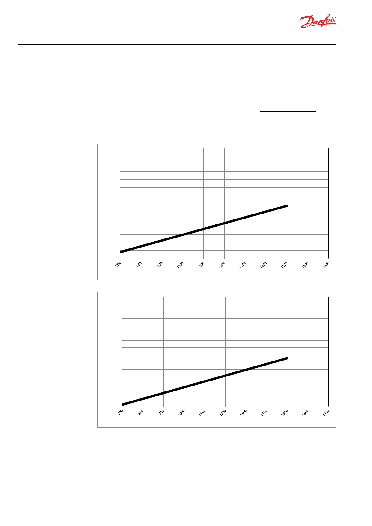
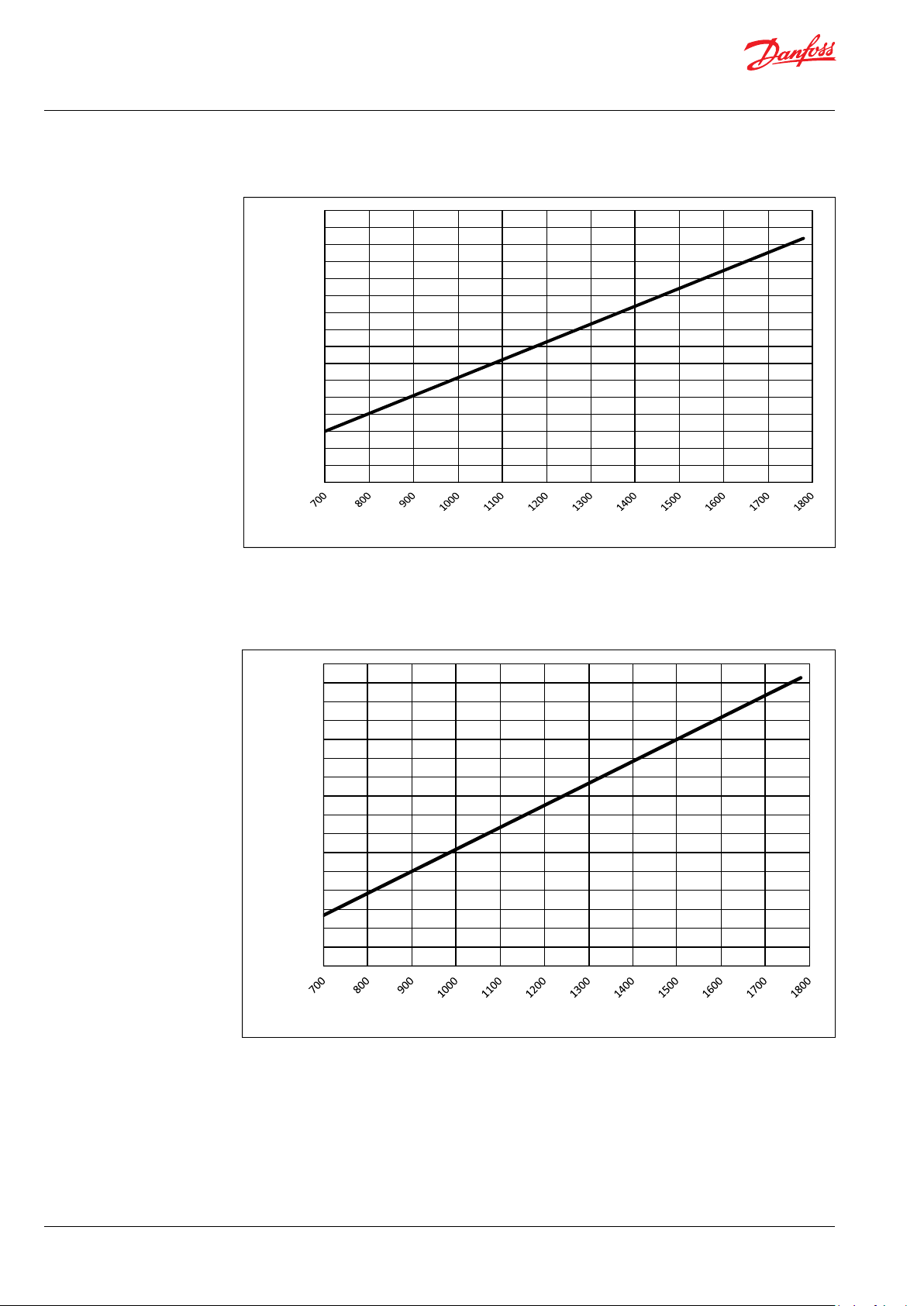
5. Performance curves
If the flow required and the rotation speed (rpm)
of the pump is known, it is easy to select the
pump, fitting the application best, by using the
diagram below.
5.1 APP 53 flow at different rpm
90,00
85,00
80,00
75,00
70,00
65,00
60,00
55,00
50,00
Flow [m3/h]
45,00
40,00
35,00
30,00
25,00
20,00
Furthermore, this diagram shows that the
flow can be changed by changing the rotation
speed of the pump. The flow/rpm ratio is
constant, and the “required” flow can be
obtained by changing the rotation speed to a
corresponding value. Thus, the required rpm
can be determined as:
Required flow x Rated rpm
Required rpm =
Rated flow
24 | © Danfoss | DCS (im) | 2021.12
Speed [RPM]
180R9346 | IOM APP 53-92 pumps | AQ240486503020en-001701
Data sheet | APP 53-92 Pumps
20,00
25,00
30,00
35,00
40,00
45,00
50,00
55,00
60,00
65,00
70,00
75,00
80,00
85,00
90,00
Flow [m3/h]
Speed [RPM]
100,00
120,00
140,00
160,00
180,00
200,00
220,00
240,00
260,00
280,00
300,00
320,00
340,00
360,00
380,00
400,00
Flow [gpm]
Speed [RPM]
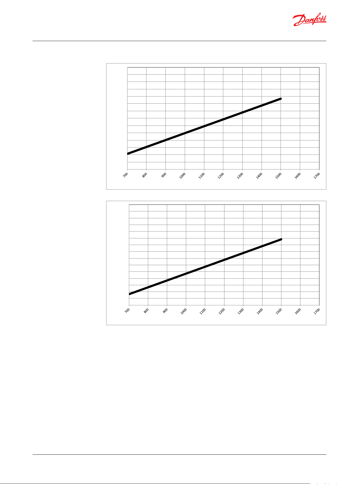
5.2 APP 65 flow at different rpm
© Danfoss | DCS (im) | 2021.12
180R9346 | IOM APP 53-92 pumps | AQ240486503020en-001701 | 25

Data sheet | APP 53-92 Pumps
20,00
25,00
30,00
35,00
40,00
45,00
50,00
55,00
60,00
65,00
70,00
75,00
80,00
85,00
90,00
Flow [m3/h]
Speed [RPM]
5.3 APP 78 flow at different rpm
26 | © Danfoss | DCS (im) | 2021.12
400,00
380,00
360,00
340,00
320,00
300,00
280,00
260,00
240,00
Flow [gpm]
220,00
200,00
180,00
160,00
140,00
120,00
100,00
Speed [RPM]
180R9346 | IOM APP 53-92 pumps | AQ240486503020en-001701
Data sheet | APP 53-92 Pumps
100,00
120,00
140,00
160,00
180,00
200,00
220,00
240,00
260,00
280,00
300,00
320,00
340,00
360,00
380,00
400,00
Flow [gpm]
Speed [RPM]
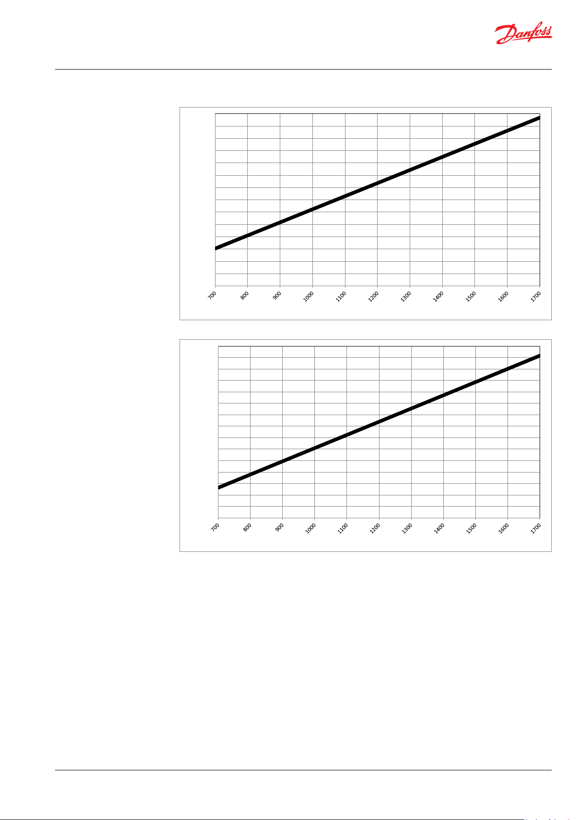
5.3 APP 86 flow at different rpm
90,00
85,00
80,00
75,00
70,00
65,00
60,00
55,00
50,00
Flow [m3/h]
45,00
40,00
35,00
30,00
25,00
20,00
Speed [RPM]
© Danfoss | DCS (im) | 2021.12
180R9346 | IOM APP 53-92 pumps | AQ240486503020en-001701 | 27
Data sheet | APP 53-92 Pumps
20,00
25,00
30,00
35,00
40,00
45,00
50,00
55,00
60,00
65,00
70,00
75,00
80,00
85,00
90,00
95,00
100,00
Fl ow [m3/h]
Speed [RP M]
100,00
120,00
140,00
160,00
180,00
200,00
220,00
240,00
260,00
280,00
300,00
320,00
340,00
360,00
380,00
400,00
420,00
Fl ow [gpm]
Speed [RPM]
5.4 APP 92 flow at different rpm
28 | © Danfoss | DCS (im) | 2021.12
180R9346 | IOM APP 53-92 pumps | AQ240486503020en-001701
Data sheet | APP 53-92 Pumps
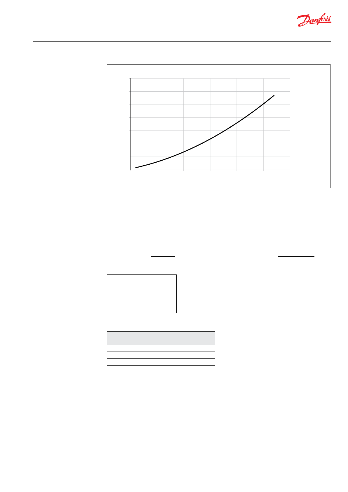
6. Flushing valve curves
6.1 APP 53-92 integrated flushing valve
Pressure [barg]
3.5
3.0
2.5
2.0
1.5
1.0
0.5
0
0
100
200
300
400
500
Flow [l/min]
600
The power requirements can be determined using one of the following guiding equations:7. Motor requirements
3
l/min x barg 16.7 x m
/h x barg 0.35x gpm x psig
Required power = [kW] or [kW] or
Calc. factor Calc. factor Calc. factor
1 hp = 0.75 kW
1 gpm = 3.79 l/min
3
1 m
/h = 4.40 gpm
1 kW = 1.34 hp
1 l/min = 0.26 gpm
1 gpm = 0.23 m
3
/h
7.1 Calculation factor at 60 barg / 870 psig for APP 53-92
Name rpm
APP 53 1500 528
APP 65 150 0 534
APP 78 150 0 534
APP 86 170 0 528
APP 92 178 0 522
Calculation
factor
[Hp]
© Danfoss | DCS (im) | 2021.12
180R9346 | IOM APP 53-92 pumps | AQ240486503020en-001701 | 29
Data sheet | APP 53-92 Pumps
8. Temperature and
corrosion
8.1 Operation
The chart below illustrates the corrosive
resistance of different types of stainless steel
related to NaCl concentration and temperature.
All wetted parts of the APP pump are made of
Duplex or Super Duplex.
º
80
C
Duplex
70
60
50
316L
40
30
20
100
160 1600
1000
10 000
16000
If the water pump is operated at high salinity
always flush the water pump with fresh water at
operation stop in order to minimize the risk of
crevice corrosion.
NaCI vs. temperature
Super Duplex
-
100 000
160000
CI
ppm
NaCI
ppm
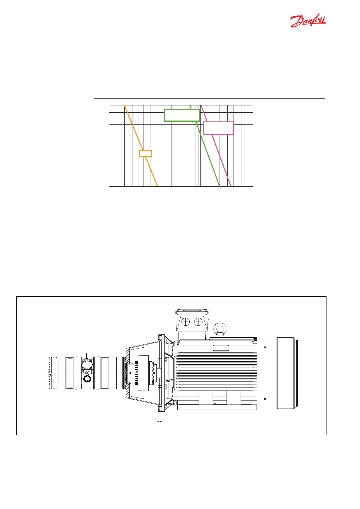
9. Installation See example below on how to mount the pump
and connect it to an electric motor or combustion engine (special coupling).
For further instruction on installation of coupling
see APP Pump Instruction 180R9368.
If alternative mounting is required. please
contact your Danfoss sales representative for
further information.
Note: Do not add any axial or radial loads to the
pump shaft.
30 | © Danfoss | DCS (im) | 2021.12
180R9346 | IOM APP 53-92 pumps | AQ240486503020en-001701

Data sheet | APP 53-92 Pumps
9.1 Filtration
Proper filtration is crucial for the performance,
maintenance and warranty of your pump.
Protect your pump, and the application in which
it is installed, by always ensuring that all filtration
specifications are met, and by always changing
filter cartridges according to schedule.
Since water has very low vicosity, Danfoss APP
pumps have been designed with very narrow
clearances in order to control internal leakage
rates and improve component performance.
To minimize wear on the pump, it is therefore
essential to filter inlet water properly.
The main filter must have a filtration efficiency of
99.98% at 10 μm. We strongly recommend that
you always use precision depth filter cartridges
rated 10μm abs. ß
≥5000.
10
Please note that we do not recommend bag
filters or string-wound filter cartridges, which
typically have only 50% filtration efficiency. This
means that out of the 100,000 particles that
enter such filters, 50,000 particles pass right
through; compare this to precision depth filters
that are 99.98% efficient, and only allow 20 of the
same 100,000 particles to pass through.
For more information on the importance of
proper filtration, including explanation of
filtration principles, definitions and guidance on
how to select the right filter for your pump,
please consult our Filtration information and
specifications (Danfoss document number
521B1009).
Noise
Since the pump unit is typical mounted on a
frame or bell housing the overall noise level can
only be determined for a complete system. To
minimize vibrations and noise throughout the
system, it is therefore very important to mount
the pump unit correctly on a frame with
anti-vibration-dampeners, and to use flexible
hoses rather than metal pipes where possible.
The noise level is influenced by:
• Pump speed:
High rpm generates more fluid/structure
borne pulsations/vibrations than low rpm,
because of higher frequency.
• Discharge pressure:
High pressure generates more noise than
low pressure.
• Pump mounting:
Rigid mounting generates more noise than
flexible mounting, because of structureborne vibrations. Be sure to use dampeners
when mounting.
• Connections to pump:
Pipes connected directly to the pump make
more noise than flexible hoses, because of
structure-borne vibrations.
• Variable frequency drives (VFD):
Motors regulated by VFDs can produce
more noise if the VFD does not have the
right settings.
•
9.2 RO system with direct supply:
Inlet line:
a) Dimension the inlet line to obtain mini
mum pressure loss (large flow, minimum
pipe length, minimum number of bends/
connections, and fittings with low or no
pressure losses) .
Inlet filter:
b) Install an inlet filter (1) in front of the APP
pump (2). Please consult section 9.1,
“Filtration” for guidance on how to select
the right filter. Thoroughly clean pipes and
flush system prior to start-up.
Inlet pressure:
c In order to eliminate the risk of cavitation
and other pump damage, pump inlet
pressure must always be maintained
according to specifications described in
item 4 about technical data.
Low pressure relief valve:
d) Install a low pressure relief valve (9) in order
to avoid system or pump damage in case
the pump stops momentarily or is spinning
backwards.
Monitoring pressure switch:
e Install a monitoring pressure switch (3)
between the filter (1) and the pump inlet.
Set the minimum inlet pressure according
to specifications described in item 4 about
technical data. If the inlet pressure is lower
than the minimum pressure set, the
monitoring pressure switch must prevent
the pump from starting or from running.
Hoses:
f) Always use flexible hoses (4) to minimize
vibrations and noise. Please consult the
Danfoss Hoses and hose fittings data
sheet (521B0909) for guidance.
Flushing valve:
g) For easy system filling and flushing, the
APP pump has an integrated valve (6).
Non-return valve:
h) A non-return valve (7) in outlet can be
installed in order to avoid backspin of the
pump. The volume of water in the
membrane vessel works as an accumulator
and will send flow backwards in case the
pump stops momentarily.
© Danfoss | DCS (im) | 2021.12
180R9346 | IOM APP 53-92 pumps | AQ240486503020en-001701 | 31

Data sheet | APP 53-92 Pumps
High pressure safety or relief valve:
i) As the Danfoss APP pump begins to create
pressure and flow immediately after
start-up and regardless of any counter
pressure, a safety or pressure relief valve (8)
should be installed after the non-return
valve to prevent system damage and to
avoid high pressure peaks.
Note: If a non-return valve is mounted in the inlet
line, a low-pressure relief valve is also required
between the non-return valve and
pump as protection against high-pressure peaks.
Feed
Media filter
PI
PI
PI PI
Fresh water
permeat flush
M
PT
PI
Brine
Permeate
PI
32 | © Danfoss | DCS (im) | 2021.12
180R9346 | IOM APP 53-92 pumps | AQ240486503020en-001701

Data sheet | APP 53-92 Pumps
connections
10.1 APP 5310. Dimensions and
© Danfoss | DCS (im) | 2021.12
180R9346 | IOM APP 53-92 pumps | AQ240486503020en-001701 | 33

Data sheet | APP 53-92 Pumps
10.2 APP 65 - 92
34 | © Danfoss | DCS (im) | 2021.12
APP 65 - 92
180R9346 | IOM APP 53-92 pumps | AQ240486503020en-001701

Data sheet | APP 53-92 Pumps
The APP 53-92 connections (inlet and outlet) can be adjusted in intervals of 45 degrees.
Please see typical installations with check valve VCM 92 mounted in the outlet port in the drawing
below. Non-standard configurations are available on request. For adjustment on site, please see
Installation, Operation and Maintenance Manual or contact Danfoss.
Non-standard configuration, turned 90 degrees left.
Non-standard configuration, turned 45 degrees left.Standard configuration
Non-standard configuration, turned 180 degrees .
© Danfoss | DCS (im) | 2021.12
180R9346 | IOM APP 53-92 pumps | AQ240486503020en-001701 | 35

Data sheet | APP 53-92 Pumps
10.3 APP 53-92 with IE3 motor, IEC 315S - 4
10.4 APP 53-92 with IE3 motor, IEC 315M - 4
36 | © Danfoss | DCS (im) | 2021.12
180R9346 | IOM APP 53-92 pumps | AQ240486503020en-001701

Data sheet | APP 53-92 Pumps
10.5 APP 53-92 with IE3 motor, IEC 315L 1-4
10.6 APP 53-92 with IE3 motor, IEC 315L 2 - 4
© Danfoss | DCS (im) | 2021.12
180R9346 | IOM APP 53-92 pumps | AQ240486503020en-001701 | 37

Data sheet | APP 53-92 Pumps
11. Pump connections
11.1 APP 53 - 92
Use only Style 77DX coupling or equivalent.
3” Victaulic OSG LP Inlet
3” Victaulic OSG HP Outlet
38 | © Danfoss | DCS (im) | 2021.12
Connection
3” Inlet
connector
3” outlet
connector
1
) The installation instuction for Style 77DX is located in the Victaulic document I-100 Field Installation
Diameter
(A)
87. 8 m m
(3.46 inch)
87. 8 m m
(3.46 inch)
Victaulic
3” Vic. OSG
3” Vic. OSG
(B)
1)
Length
(C)
61.0 mm
(2.40”)
65.0 mm
(2.56”)
Material Max. Pressure Code number
Super
Duplex
Super
Duplex
10 barg
(145 psi g)
80 barg
(1160 ps ig)
180Z1991
180Z1992
Handbook (htpp://static.victaulic.com)
180R9346 | IOM APP 53-92 pumps | AQ240486503020en-001701

Data sheet | APP 53-92 Pumps
12. VCM 3” Victaulic
The non-return valve is designed for use in
Seawater Reverse Osmosis (SWRO) membrane
systems. In case the high-pressure pump stops
momentarily, the volume of water in the
membrane vessel may work as an accumulator
and will send flow backwards.
When using multiple pumps in parallel, the
non-return valve
12.1 Techni cal data
prevents the water from one pump to run into
the parallel-coupled pumps at start-up.
The VCM 92 is prepared for easy installation on
the high pressure outlet of APP 53-92, series 08
or higher..
Use only Style 77DX coupling or equivalent.
Diameter
valve
)
1)
mm (inch)
87. 7
(3.45)
Typ e Connection
VCM 92
1)
The check valve is mounted directly in the outlet port with a flange with 8 screws M12 x 25.
2)
Wetted parts materials: Super Duplex, PEEK, PP, Hasteloy; FKM, NBR
3)
The installation instuction for Style 77DX is located in the Victaulic document I-100 Field Installation
3” outlet check
Victaulic
(outlet
connection)
3)
3” Vic. OSG
Length
mm (inch)
180.5
(7.10)
Material2
Super
Duplex
Max.
2)
pressure
barg (psig)
83 (1.200) 180H0058
Code
number
Handbook (htpp://static.victaulic.com)
VCM VCM 92
Min. flow continously
Max. flow continously
Max pressure MAWP
Opening pressure barg 0.05- 0.08
Pressure loss at max. flow barg < 0.45
m³/h 20
gpm 88
m³/h 92
gpm 405
barg 83
psig 1200
psig 0.73-1.16
psig < 6.5
© Danfoss | DCS (im) | 2021.12
180R9346 | IOM APP 53-92 pumps | AQ240486503020en-001701 | 39

Data sheet | APP 53-92 Pumps
0
0,05
0,1
0,15
0,2
0,25
0,3
0,35
0,4
0,45
0,5
20 25 30 35 40 45 50 55 60 65 70 75 80 85 90 95 100
dP [ bar ]
Flow [ m3/h ]
Flow versus pre ssure f or VCM 92
1
2
3
4
5
6
7
80 100 120 140 160 180 200 220 240 260 280 300 320 340 360 380 400 420 440
dP [ PSI ]
Flow [ GPM]
Flow versus pre ssure f or VCM 92
1. Valve housing (Super Duplex)
2. Valve guide and valve stop (Super Duplex,
PEEK and PP)
3. Valve Cone (Super Duplex)
5. Spring (Hasteloy)
6. O-ring (NBR)
7. O-ring (FKM 75)
8. O-ring (NBR)
12.2 Flow versus pressure
Pressure drop curves for check valve VCM 92
40 | © Danfoss | DCS (im) | 2021.12
180R9346 | IOM APP 53-92 pumps | AQ240486503020en-001701

Data sheet | APP 53-92 Pumps
13. Accessories
14. Service and warranty
Accessories Typ e Code num-
Coupling APP 53 - APP 92 IEC 315 Diameter: motor Ø80 mm, pump Ø50 180Z4066
Coupling APP 53 - APP 92 IEC 280 Diameter: motor Ø75 mm, pump Ø50 180Z4081
Coupling kit APP 53 - APP 92 incl. bell housing IEC 315 Ø80/Ø50. IEC 315 Ø660/310 180Z4083
Coupling kit APP 53 - APP 92 incl. bell housing IEC 280 Ø75/Ø50. IEC280 Ø550/265 18 0Z4082
Base frame incl. vibration dampeners IEC 315 180Z06 61
Warranty
Danfoss APP pumps are designed for long
operation, low maintenance and reduced
lifecycle costs.
Pump shutdown:
The APP pumps are made of Duplex/Super
Duplex materials with excellent corrosion
properties. It is, however, always recommended
to flush the pump with freshwater when the
Provided that the pump has been running
according to the Danfoss specifications, Danfoss
guarantees 8,000 hours service-free operation,
however, max. 18 months from date of
production.
system is shut down.
When stopping the pump for more than 1 day
flush the pump for 10 sec. Flushing through the
flushing valve of the pump without rotating the
pump is not enough for cleaning the inside of
the pump.
If Danfoss recommendations concerning
system-design are not followed, it will strongly
influence the life of the APP pumps.
Other factors that affect pump performance and
lifetime include:
The pump can be flushed with biocide like the
membranes. The biocide must be compatible
with the materials used in our pump (materials
can be found in the parts list in the instruction
and operational manual).
- Insufficient filtration
- Insufficient bleeding and venting
- Running the pump at speed outside
specifications.
Repair
In case of irregular function of the APP pump,
please contact Danfoss High Pressure Pumps.
- Supplying the pump with water at
temperature higher than recommended.
- Running the pump at inlet pressure outside
specifications.
- Running the pump at outlet pressure
outside the specifications.
- Wrong direction of rotation.
Maintenance
After 8,000 hours of operation it is strongly
recommended to inspect the pump and change
any worn parts, e.g. pistons and shaft
seal. This is done in order to prevent a potential
breakdown of the pump. If the parts are not
replaced, more frequent inspection is
recommended according to our guidelines.
ber
© Danfoss | DCS (im) | 2021.12
180R9346 | IOM APP 53-92 pumps | AQ240486503020en-001701 | 41

© Danfoss | DCS (im) | 2021.12
AI167386503010en-001301 | 42

Instruction
APP Pump Instruction
APP 53 / APP 65 / APP 78 / APP 86 / APP 92
hpp.danfoss.com

Instruction | APP Pump Instruction APP 53-92
Table of Contents
Table of Contents
1. Identification ......................................................................... 44
2. System design .........................................................................45
2.1 Open-ended systems with direct water supply..........................................45
2.2
Preferred RO system design without ERD .................................................45
2.3 Preferred RO system design with ERD...................................................46
2.4 Preferred RO system design with pumps and ERDs in parallel ...........................46
2.5 Reversible pumps ......................................................................46
3. Building up the pump unit with BoWex coupling........................................46
3.1 Assembly of the coupling ..............................................................46
3.2 Alignment between the motor and pump shaft.........................................46
3.3 Overall assembly with coupling BoWex-ELASTIC®, type HEW compact ...................47
3.3.1 Mounting ..............................................................................48
3.4 Direction of rotation ...................................................................49
3.5 Orientation ............................................................................49
3.6 Protection from too high pressures .....................................................49
4. Building up the pump unit with jaw coupling ...........................................49
4.1 Mounting..............................................................................49
4.2 Connections ...........................................................................50
5. Initial start-up..........................................................................51
6. Operation..............................................................................52
6.1 Temperature...........................................................................52
6.2 Pressure ...............................................................................52
6.3 Dry running............................................................................52
6.4 Disconnection .........................................................................52
6.5 Storage ................................................................................53
1. Identification
7. Service and warranty...................................................................53
PUMP
Type APP 78
Code no. 180BXXXX
Serial no. XXXXXX08-XXX
MADE IN DENMARK
Danfoss A/S, 6430 Nordborg, Denmark
44 | © Danfoss | DCS (im) | 2021.12 180R9346 | IOM APP 53-92 pumps | AQ240486503020en-001701

Instruction | APP Pump Instruction APP 53-92
2. System design
The design of the system must ensure that
self-emptying of the pump during standstill is
avoided.
The inlet pressure of the pump must never
exceed the outlet pressure. This may typically
occur in boosted or open-ended systems with
direct water supply.
2.1 Open-ended systems with direct water
supply
Axial piston pumps require a certain inlet
pressure to perform as intended. Please find min.
required feed pressure in the pump data sheet.
Please also note that feed pressure must not
exceed 5 barg (72.5 psig).
2.2
Preferred RO system design without ERD
1. Dimension the inlet line to obtain minimum pressure loss (large flow, minimum
pipe length, minimum number of bends/
connections, and fittings with small
pressure losses).
2. Place an inlet filter (1) in front of the APP
pump (2). Please consult Danfoss filter data
sheet for guidance on how to select the
right filter. Thoroughly clean pipes and
flush system prior to start-up.
3. Place a monitoring pressure switch (3) set
at min. inlet pressure between filter and
pump inlet. The monitoring switch must
stop the pump at pressures lower than
minimum pressure.
4. Use flexible hoses (4) to minimize vibrations
and noise.
5. In order to eliminate the risk of damage
and cavitation, a positive pressure at the
inlet (5) is always to be maintained at min.
inlet pressure and max. inlet pressure.
To protect the pump from being damaged by
peaks of high-pressure in case the pump stops
momentarily, it is required to mount a lowpressure relief valve on the inlet line.
Note: The inlet connection must be properly
tightened, as possible entrance of air will cause
cavitation.
It is recommend to install safety valve or a
pressure relief valve (9) in order to avoid
high-pressure peaks in case the pump stops
momentarilly or is spinning backwards.
6. For easy system bleeding and flushing, a
bypass non-return valve (6) is integrated in
the APP pump.
7. A non-return valve (7) in outlet can be
installed in order to avoid backspin of the
pump. The volume of water in the membrane vessel works as an accumulator and
will send flow backwards in case of the
pump stops momentarily.
8. A safety valve or a pressure relief valve (8)
can be installed in order to avoid system
damage as the Danfoss APP pump creates
pressure and flow immediately after startup, regardless of any counter pressure.
Note: If a non-return valve is mounted in the
inlet line, a low-pressure relief valve is also
required between non-return valve and pump
as protection against high-pressure peaks.
Feed
Media filter
PI
PI
PI PI
Fresh water
permeat flush
PT
M
PI
PI
Brine
Permeate
© Danfoss | DCS (im) | 2021.12 180R9346 | IOM APP 53-92 pumps | AQ240486503020en-001701 | 45

Instruction | APP Pump Instruction APP 53-92
2.3 Preferred RO system design with ERD
For P&ID of a setup with an iSave, please see the
iSave® Data sheet 521B1378
2.4 Preferred RO system design with pumps
and ERDs in parallel
For systems with Danfoss pumps and ERDs in
parallel, please see our publication 180R9354,
Guideline for Parallel-coupled pumps and ERD.
2.5 Reversible pumps
If exposed to high-pressure in the outlet while
the electric motor is not energized, the pumps
may start spinning backwards. This will not harm
the pumps as long as the pressure in the inlet
does not exceed the max. pressure peak of
10 barg(145 psig).
If a non-return valve is mounted in the inlet line,
a low-pressure relief valve is required as protection against high-pressure pulses and high-pressure in general.
Alternatively a high-pressure check valve can be
mounted in the pump discharge line to prevent
the pump from reversing.
The setup of “open-end system” ensures that the
inlet pressure does not exceed 10 barg (145 psig),
when a nonreturn valve is mounted in the inlet.
2.6 General comments
A good filtration is vital to ensure a long and
trouble-free life of the pump.
As water has very low viscosity, the APP pumps
have been designed with very narrow clearance
in order to control internal leakage rates and
improve component performance. Therefore it is
important that the inlet water is filtered properly
to minimize the wear of the pump.
The main filter must have a filtration efficiency of
99.98% at 10 μm. We recommend to use
precision depth filter cartridges rated 10 μm abs.
β10 ≥ 5000 (equivalent to a filtration efficiency of
99.98%). Bag filters and string wounded filter
cartridges typically have only 50% filtration
efficiency. This means that for each 100,000 particles reaching the filter, 50,000 particles pass
through it compared to only 20 particles in a
filter with an efficiency of 99.98%.
For more information on the importance of
proper filtration, please see our data sheet
521B1009 on “Filtration”, which also will provide
you with an explanation of filtration definitions
and a guidance on how to select the right filter.
Monitoring
It is recommended to continuously monitor the
following conditions:
• Filter clogging
• Pressure (inlet- and outlet side of the
pump)
3. Building up the
pump unit with BoWex
coupling
3.1 Assembly of the coupling
We recommend to inspect bores, shaft,
keyway and feather key for dimensional
accuracy before assembly.
Heating the hubs lightly (approx. 80 °C)
allows for an easier mounting on the
shaft.
Please pay attention to the ignition risk
in potentially explosive atmospheres!
3.2 Alignment between the motor and
pump shaft
Touching the heated hubs causes
burns.
Please wear safety gloves.
With the assembly please make sure
that the spline of the hub is fully covered by the internal spline of elastomer (please observe mounting dimensions L
may cause damage to the coupling.
). Disregarding this advice
coupling
max. 0. 5 mm
max. 0.02 i nch
46 | © Danfoss | DCS (im) | 2021.12 180R9346 | IOM APP 53-92 pumps | AQ240486503020en-001701

Instruction | APP Pump Instruction APP 53-92
3.3 Overall assembly with coupling
BoWex-ELASTIC®, type HEW compact
Danfoss recommends to use a Bowex Elastic HEW
Compact Coupling.
See the Coupling Manual from BoWex.
1: Bolts 190 Nm ± 10
2: Nuts 100 Nm ± 10
3: Torque see ta ble
Component
Thread size M5 M6 M8 M10
Torque [Nm] 2 4.8 10 17
Quantity Description
1 1 Elastomer part
2 1 Hub
4 1 Coupling flange
5
10
7 2
Cap screws
DIN EN ISO 4762
Setscrews
DIN EN ISO 4029
© Danfoss | DCS (im) | 2021.12 180R9346 | IOM APP 53-92 pumps | AQ240486503020en-001701 | 47

Instruction | APP Pump Instruction APP 53-92
3.3.1 Mounting
1. Mount the coupling flange (component 4)
in front of the elastomer part (component
1) and screw the components together
with a tightening torque of 120 Nm.
Lubricate inside the coupling hubs (not the
shafts).
If used in potentially explosive atmospheres the setscrews to fasten the hubs
as well as all screw connections must be
secured against working loose additionally, e.g. conglutinating with Loctite
(average strength).
Please observe the manufacturer’s
instructions regarding the use of adhesives. Do not apply glue on the rubber
surfaces.
2. Mount the bell housing on pump. Secure
nuts with the right torque.
3. Push the coupling part all the way down to
the shoulder of the pump shaft and secure
with right torque on the locking screws.
Measure the distance “a” from the end of
the bell housing to the end of the toothing
of the coupling.
4. Mount the coupling on motor shaft
without using hammer. If needed then
polish motor shaft/key and inside coupling
hub.
5. On the motor shaft position the coupling
so that the length from the end of the
coupling to the end of the motor flange is
“b= a+32.5 mm” ± 2 mm.
6. Secure coupling on motor shaft with the
right torques on the locking scre+ws.
7. Connect carefully pump/bell housing to
motor. Turn motor shaft so coupling tooths
can interact.
8. Mount motor flange bolts to bell housing
and tighten with the right torque.
9. Check coupling space. The pump coupling
should be in a position so there is still
3-7 mm space.
If alternative mounting is desired, please contact
Danfoss High Pressure Pumps.
Please take care to observe the recommended
length tolerances of the chosen coupling, as an
axial force on the pump will damage the pump.
b = a + 32.5 mm ± 2 mm
48 | © Danfoss | DCS (im) | 2021.12 180R9346 | IOM APP 53-92 pumps | AQ240486503020en-001701

Instruction | APP Pump Instruction APP 53-92
3-5 mm
[0.12-0.20 inch]
3.4 Direction of rotation
Is indicated by an arrow engraved in the flange
of the pump.
3.5 Orientation
APP 53-92 can be mounted/orientated in steps of
The opening characteristics of the valve must not
result in peak pressures higher than 100 barg
(1450 psig).
The valve should be placed as close to the pump
as possible.
45 degrees. Please see Data sheet 521B1340.
We recommend to install flexible soft hoses both
3.6 Protection from too high pressures
in the inlet and outlet lines.
The pump should be protected against too high
pressure by means of a safety valve or a pressure
relief valve.
The valve outlet must not be connected directly to the pump suction line.
It must be connected directly to the drain.
Outlet
Outlet Inlet
4. Building up the
pump unit with jaw
coupling
D
Inlet
A: Elastic coupling
B: Bell housing
C: Motor shaft
D: Pump flange
4.1 Mounting
1. Mount the coupling flush with the pump
shaft end or maximum 1 mm offset from
the pump shaft end. Ensure an air gap
between coupling parts of 3-5 mm (0.12-0.2
inch).
2. Mount the bell housing on pump. Secure
nuts with the right torque.
3. Measure the longest distance “A” from top
of bell housing to the button of coupling
claw.
IMPORTANT
When using jaw coupling it is critiacal
that the recommended measurements are kept.
max. 0. 25 mm
max. 0.01 inch
4. Mount the coupling on motor shaft. Ensure
the coupling and motor flange are not in
contact with each other.
5. Measure from motor flange to the top of
the coupling. That measurement “B” shall
be 3-5 mm (0.12-0.2 inch) shorter than the
measurement “A”.
(“A” and “B” can be found on the next
page).
© Danfoss | DCS (im) | 2021.12 180R9346 | IOM APP 53-92 pumps | AQ240486503020en-001701 | 49

Instruction | APP Pump Instruction APP 53-92
Bolts and nuts
torque
6. Adjust respectively, verify the measurement, and secure both couplings with the
right torques on the locking screws (see
coupling operation & mounting instruction).
7. Mount the elastic gear ring and mount the
bell housing/pump on the motor. After
mounting it must be possible to move the
elastic gear ring 3-5 mm (0.12 - 0.2 inch)
axial “C”. The check can be done through
the inspection hole of bell housing. Secure
flange bolts with the right torque.
1: Bolts 100 Nm ± 10
2: Nuts 100 Nm ± 10
3: Torque se table below
75 Nm ± 5 Nm
1
2
C
If alternative mounting is desired, please contact
Danfoss High Pressure Pumps.
Choose proper tolerances to ensure an easy
mounting of the elastic coupling without use of
tools.
Please take care to observe the recommended
length tolerances of the chosen coupling, as an
axial force on the pump will damage the pump.
3
4.2 Connections
To prevent stray current corrosion we recommend grounding of the pump and all other parts
in the system.
All parts in the system must be electrical
potential equalized to a single reference point
(grounding point).
It is recommended that the electrical resistance
in the grounding cable is equal to or below 0.25
Ohm towards the grounding point.
Thread
size
Torque
[Nm]
M5 M6 M8 M10
2 4.8 10 17
50 | © Danfoss | DCS (im) | 2021.12 180R9346 | IOM APP 53-92 pumps | AQ240486503020en-001701

Instruction | APP Pump Instruction APP 53-92
5. Initial start-up
1. Flush inlet line before connecting the
pump, to remove possible impurities from
pipes, hoses etc.
2. Connect pump inlet to inlet line and flush
the pump for 5 min. by means of the
internal flushing valve, to remove possible
impurities from pipes, hoses etc.
3. Loosen top bleeding plug (see item 3.5)
using an allen key (only plugs with internal
hexagon sockets). Retighten the plug,
when water appears from the bleeding
plug.
4. Make sure that the direction of rotation of
the electric motor corresponds to the direction of rotation of the pump, show on the
pump flange.
5. Now the pump is ready for start-up.
WARNING
Make sure that the direction of rotation of the
electric motor corresponds to the direction of
rotation of the pump.
Otherwise the pump will be damaged if a
check valve is placed between pump and feed
pump.
O
I
Internal
flushing
valve
© Danfoss | DCS (im) | 2021.12 180R9346 | IOM APP 53-92 pumps | AQ240486503020en-001701 | 51

Instruction | APP Pump Instruction APP 53-92
6. Operation
6.1 Temperat ure
Fluid temperature:
Min. +2°C to max. +50°C
(Min. +35.6°F to max. +122°F)
Ambient temperature:
Min. +2°C to max. +50°C
(Min. +35.6°F to max. +122°F)
In case of lower operating temperatures, please
contact Danfoss High Pressure Pumps.
NaCl vs. temperature
º
C
80
Duplex
70
60
50
316L
40
The chart below illustrates the corrosive
resistance of different types of stainless steel
related to NaCl concentration and temperature.
The APP water pump is made of Duplex and
Super Duplex.
If the water pump is operated above the Super
Duplex line, always flush water pump with fresh
water at operation stop in order to minimize the
risk of crevice corrosion.
Super Duplex
30
20
100
1000
160 1600
6.2 Pressure
The inlet pressure shall be min. 2 barg (30 psig)
and max. 5 barg (72.5 psig). At lower pressures
the pump will cavitate, resulting in damage of
the pump.
Max. inlet pressure peak (e.g. in case the pump
stops momentarily) up to 10 barg (145 psig) are
acceptable.
Max. pressure on the pump’s outlet line shall be
limited at 80 barg (1160 psig) continuously.
For APP 86 min. inlet pressure shall be 2.5 barg
(36 psig) and max. outlet pressure shall be
70 barg (1015 psig).
For APP 92 min. inlet pressure shall be 3.5 barg
(50 psig) and max. outlet pressure shall be
70 barg (1015 psig).
-
10 000
16000
6.3 Dry running
When running, the pump must always be
connected to the water supply in order to avoid
damage if it should run dry.
6.4 Disconnection
If the inlet line is disconnected from the water
supply, the pump will be emptied of water
through the disconnected inlet line.
When starting up again, follow the bleeding
procedure described under section 4: Initial
start up.
100 000
160000
CI
ppm
NaCI
ppm
Note: The pump unit should include a pressure
gauge on the high-pressure side.
52 | © Danfoss | DCS (im) | 2021.12 180R9346 | IOM APP 53-92 pumps | AQ240486503020en-001701

Instruction | APP Pump Instruction APP 53-92
6.5 Storage
Storage temperature:
Min. -40°C to max. +70°C
(Min. -40°F to max. +158°F)
When preparing the pump for long-term storage
at temperatures below the freezing point, flush
the pump with an anti-freeze medium type
monopropylene glycol to prevent internal
corrosion or frost in the pump.
For further information on anti-freeze media,
please contact Danfoss High Pressure Pumps.
Recommended procedure:
1. Disconnect the water supply to the pump.
2. Through the lower bleeding plug, empty
the pump housing of water and close it
again.
3. Connect the pump to a tank containing
anti-freeze additive. Connect a hose to the
inlet port of the pump and via another
hose return the flow from the outlet port to
the tank with antifreeze additives.
4. Quickly start and stop the pump. Make
sure that the pump does not run dry.
The pump is now protected against
internal corrosion and frost.
Storage:
Storage of pump that have been in operation:
For shorter periods of storage flush the pump
with permeate by rotating the pump for 10 sec.
empty permeate and store.
For long term storage (more than 2 months)
Danfoss recommends servicing the product and
clean any biological growth of the surfaces. Store
the pump without water inside.
7. Service and warranty
Warranty
Danfoss APP pumps are designed for long
operation, low maintenance and reduced
lifecycle costs.
Provided that the pump has been running
according to the Danfoss specifications, Danfoss
guarantees 8,000 hours service-free operation,
however, max. 18 months from date of
production.
If Danfoss recommendations concerning
system-design are not followed, it will strongly
influence the life of the APP pumps.
Other factors that affect pump performance and
lifetime include:
- Insufficient filtration
- Insufficient bleeding and venting
- Running the pump at speed outside
specifications.
- Supplying the pump with water at
temperature higher than recommended.
- Running the pump at inlet pressure outside
specifications.
- Running the pump at outlet pressure
outside the specifications.
- Wrong direction of rotation.
Pump shutdown:
The APP pumps are made of Duplex/Super
Duplex materials with excellent corrosion
properties. It is, however, always recommended
to flush the pump with freshwater when the
system is shut down.
When stopping the pump for more than 1 day
flush the pump with permeate by rotating the
pump for 10 sec. Flushing through the flashing
valve of the pump without rotating the pump is
not enough for cleaning the inside of the pump.
The pump can be flushed with biocide like the
membranes. The biocide must be compatible
with the materials used in our pump (materials
can be found in the parts list in the Service guide
and Operating manual).
Repair
In case of irregular function of the APP pump,
please contact Danfoss High Pressure Pumps.
Maintenance
After 8,000 hours of operation it is strongly
recommended to inspect the pump and change
any worn parts, e.g. pistons and shaft
seal. This is done in order to prevent a potential
breakdown of the pump. If the parts are not
replaced, more frequent inspection is
recommended according to our guidelines.
© Danfoss | DCS (im) | 2021.12 180R9346 | IOM APP 53-92 pumps | AQ240486503020en-001701 | 53

© Danfoss | DCS (im) | 2021.05
AN220686503013en-000901 | 180R9368 | 521B1392 | 54

Electric Motors
Motor Manual
hoyermotors.com

Motor
Manual
General
This manual concerns the following types of standard
induction motors from Hoyer:
HMA3, HMC3, HMA2, HMC2, HMD, HMT, MS, Y2E1, Y2E2, YDT
These motors are manufactured in accordance with IEC/EN
60034-4 and IEC/EN 60072.
Motors are rated for the ambient temperature range -20°C to
+40°C and site altitudes ≤1000 m above sea level.
Low-voltage motors are components for installation in
machinery. They are CE marked according to the Low Voltage
Directive 2014/35/EU.
Motors not fulfilling the IE3 efficiency level must be equipped
with a variable speed drive when used in EU.
Transport and storage
Check the motor for external damage immediately upon
receipt and, if found, inform the forwarding agent right away.
Check all rating plate data, and compare it with the
requirement of the motor.
Turn the shaft by hand to check free rotation, remove
transport locking if used.
Transport locking must be used again for internal transport
also. It is also important that transport locking is used when
motors are transported mounted on equipment.
All motors should be stored indoors, in dry, vibration- and
dust-free conditions.
Lifting eyebolts must be tightened before use. Damaged
eyebolts must not be used, check before use. Lifting eyes at
motor must not be used to lift the motor when it is attached
to other equipment.
Before commissioning, measure the insulation impedance. If
values are ≤ 10MΩ at 25°C, the winding must be oven dried.
The insulation resistance reference is halved for each 20°C
rise in motor temperature.
It is recommended that shafts are rotated periodically by
hand to prevent grease migration.
etc.) using suitable tools, never hit the drive components
with a hammer as this will cause damage to the bearing.
The motor are balancing with half key, ensure that the drive
components are also the same.
Correct alignment is essential to avoid bearing, vibration and
shaft failure.
Use appropriate methods for alignment.
Re-check the alignment after the final tightening of the bolts
or studs.
Check that drain holes and plugs face downwards. We
recommend opening the drain hole for motors placed
outdoors and not running 24 hours / day, so that the motor
can breathe, thus ensuring a dry motor.
Electrical connection
Work is only permitted to be carried out by qualified
specialists and must to be carried out in accordance with
local regulations.
Before work commences, ensure that all power is switched
off and cannot be switched on again. This also applies to the
auxiliary power circuits, e.g. anti-condense heaters.
Check that supply voltage and frequency are the same as
rated data.
Motors can be used with a supply deviation of ± 5% voltage
and ± 2% frequency, according to IEC60034-1.
Connection diagrams for main supply and accessory as PTC
or heater are located inside the terminal box.
Connections must be made in such a way as to ensure that
a permanently safe electrical connection is maintained, both
for the main supply and the earth connection.
We recommend that crimped connections are made in
accordance with IEC 60352-2.
Tightening torques for terminal board screws:
Thread M5 M6 M8 M10 M12 M16 M20 M24
T.(Nm) 2.5 3.5 7 12 18 35 55 80
Installation
The motor must be fixed on a stable, clear and flat foundation.
It must be sufficiently rigid to withstand possible short
circuit forces.
It is important to ensure that the mounting conditions do
not cause resonance with the rotational frequency and the
doubled supply frequency.
Only mount or remove drive components (pulley, coupling,
56
180R9346 | IOM APP 53-92 pumps | AQ240486503020en-001701 | 12.2021
Ensure that the terminal box is clean and dry.
Unused glands must be closed with blind caps.
Check the terminal box gasket before it is remounted.
Maintenance
Inspect the motor at regular intervals, keep it clean and
ensure free ventilation air flow, check the condition of shaft
seals and replace if necessary. Both electrical and mechanical

Motor
Manual
connections must be checked and tightened if necessary.
Bearing size and type are specified on the rating plate. Motor
types HMA3 and HMC3 is as standard with lifetime greased
bearings in motors size ≤180 for cast iron and size ≤132 for
aluminium. Motor types HMA2 and HMC2 is as standard
with lifetime greased bearing in motors size ≤225.
Motor types MS and Y2E is as standard with lifetime greased
bearing in motors size ≤160.
Typical duty hours for lifetime lubricated bearings.
Frame size Poles Typical lifetime
56 - 160 2 - 8 40,000h
180 2 35,000h
200 2 27,000h
225 2 23,000h
180 - 225 4 - 8 40,000h
Motors with a re-greasing system must be lubricated with
high quality lithium complex grease, NLGI grade 2 or 3, with
a temperature range of between -40°C to +150°C.
Motors are normal fitted with a data plate with greasing
information; if it is missing use the following re-greasing
intervals.
Frame
size
160 20 4200 7000 8500 8500
180 20 4200 7000 8500 8500
200 25 3100 6500 8500 8500
225 25 3100 6500 8500 8500
250 35 2000 6000 7000 7000
280 35 2000 6000 7000 7000
315 50 1500 5500 6500 6500
355 60 1000 4000 5000 6000
400 80 800 3000 4000 6000
Grease
(g)
2 pole
(h)
4 pole
(h)
6 pole
(h)
8 pole
(h)
Grease the motor while running, open the grease outlet plug
and let the motor run 1-2 hours before the outlet grease plug
is closed again.
Grease the motor for the first time during commissioning.
The following applies in general for both lifetime lubricated
and re-lubricated bearings:
At 60Hz the time will be reduced by app. 20%.
Data for vertically mounted motors are half of the above
values.
The table values are based on an ambient temperature of
25°C. The values must be halved for every 15K increase in
bearing temperature.
Higher speed operations, e.g. frequency converter drive will
require shorter greasing intervals. Typically, doubling the
speed will reduce the values by 50%.
Special note for Atex Zone 22 and nA motors
Designation of motor according to IEC standard:
II 3D Ex tc IIIB T120°C
II 3G Ex nA IIC T3
The hazardous 3-phase asynchronous motors are in
accordance with International standard IEC 60079-31 and
IEC 60079-15.
Only one electrical installation may be installed in one
specified area (zone).
Only certificated cable glands may be used. Unused glands
must be closed.
Connections must be made in such a way as to ensure that
a permanently safe electrical connection is maintained, both
for the main supply and earth connection.
Installations must be in accordance with actual standards
for installation in hazardours area.
It is recommended that the IEC standard is followed according
to temperature and dust on the motor surface.
The use of motors with so much surface dust that the motor
temperature increases is not permitted.
Regularly cleaning is recommended.
The radial shaft sealing ring is part of the ATEX certification.
It is important that the ring is always intact.
The shaft sealing must be regularly checked, and if dry it
must be lubricated. It is recommended that the seal is relubricated regularly.
Always use the original seal ring when replaced.
Replacing bearings also means replacing the seals.
All machines must be inspected regularly for mechanical
damage.
The user is responsible for changing parts in accordance
with the lifetime of parts, in particular:
bearings, grease and lubrication of shaft sealing.
Maintenance, repairs and replacement on this type must
only be carried out by qualified specialists.
3
180R9346 | IOM APP 53-92 pumps | AQ240486503020en-001701 | 12.2021 |
57

Connection diagram
Anschlußdiagram
Anslutningdiagramm
Forbindelsesdiagram
Aansluitdiagram
Connection
Conexión
Collegamento
Schemat polacsen
58
180R9346 | IOM APP 53-92 pumps | AQ240486503020en-001701 | 12.2021

180R9346 | IOM APP 53-92 pumps | AQ240486503020en-001701 | 12.2021 |
59

Hoyer Motors, Motor Manual, April 2019
Head Offices
Over Hadstenvej 42 · DK-8370 Hadsten
T +45 86 98 21 11 · F +45 86 98 17 79
hoyermotors@hoyermotors.com
19 Jingwu Middle Road · Beilun District
T +86 574 26 28 15 77 · F + 86 574 2628 1573
hoyermotors@hoyermotors.cn
Important notice.
Denmark
CVR no. 17 63 06 95
hoyermotors.com
China
Ningbo 315821 · Zhejiang
hoyermotors.cn
Text and data in this catalogue are not binding and we reserve the right to implement changes without further notice.
60
Branch Offices
Landsberger Straße 155 · 80687 München
Germany
T +49 89 700 88 235 · F +49 89 543 56 333
germany@hoyermotors.com
hoyermotors.com
Sweden
Liljeholmsstranden 5 · PO box 44017
SE-100 73 Stockholm
T +46 8 446 877 13
sweden@hoyermotors.com
hoyermotors.com
Vasteland 78 · 3011 BN, Rotterdam
Tel. +31 10 420 35 20 · Fax.+31 10 420 44 51
benelux@hoyermotors.com
302ho · Code square · 3150-1 · Daejeo 2-dong
Gangseo-gu · Busan · Korea
T +82 51 996 0251 · F +82 51 996 0252
korea@hoyermotors.com
Benelux
hoyermotors.com
Korea
hoyermotors.com
180R9346 | IOM APP 53-92 pumps | AQ240486503020en-001701 | 12.2021

BoWex-ELASTIC®
Type HEW, HEW Compact and HEW-ZS
KTR-N
Edition:
40114 EN
1
7
Please observe protection
note ISO 16016.
Drawn:
2017-04-24 Shg/Hk
Replacing:
KTR-N dated 2013-06-10
Verified:
2017-04-24 Shg
Replaced by:
Type HEW1
Type HEW2
Type HEW Compact
Type HEW-ZS
Operation guide | Installation, Operation and Maintenance APP 53-92 pumps
Operating/Assembly instructions
Sheet:
of 22
BoWex-ELASTIC
highly flexible flange coupling type
HEW1, HEW2 and their combinations
according to directive 2014/34/EU
for finish bored, pilot bored and unbored couplings
®
BoWex-ELASTIC®
highly flexible flange coupling types
HEW Compact and HEW-ZS and their combinations
for finish bored, pilot bored and unbored couplings
© Danfoss | DCS (im) | 2021.12
180R9346 | IOM APP 53-92 pumps | AQ240486503020en-001701 | 61

BoWex-ELASTIC®
Type HEW, HEW Compact and HEW-ZS
KTR-N
Edition:
40114 EN
2
7
Please observe protection
note ISO 16016.
Drawn:
2017-04-24 Shg/Hk
Replacing:
KTR-N dated 2013-06-10
Verified:
2017-04-24 Shg
Replaced by:
Table of contents
Operation guide | Installation, Operation and Maintenance APP 53-92 pumps
Operating/Assembly instructions
Sheet:
of 22
BoWex-ELASTIC® HEW is a highly flexible plug-in shaft coupling. It dampens torsional vibrations, reduces shocks and insulates structure-borne noise.
The BoWex-ELASTIC
®
HEW coupling compensates for relatively large shaft displacements,
for example caused by inaccuracies in production, thermal expansion etc.
1 Technical data 3
2 Advice 6
2.1 Coupling selection 6
2.2 General advice 6
2.3 Safety and advice symbols 7
2.4 General hazard warnings 7
2.5 Intended use 7
2.6 Reference to EC Machinery Directive 2006/42/EC 8
3 Storage, transport and packaging 8
3.1 Storage 8
3.2 Transport and packaging 8
4 Assembly 8
4.1 Components of the couplings 8
4.2 Advice for finish bore 10
4.3 Assembly of the coupling 11
4.4 Displacements - alignment of the couplings 12
5 Start-up 15
6 Breakdowns, causes and elimination 16
7 Disposal 18
8 Spares inventory, customer service addresses 18
9 Enclosure A Advice and instructions regarding the use in potentially explosive
atmospheres 18
9.1 Intended use in hazardous locations 18
9.2 Inspection intervals for couplings in potentially explosive atmospheres 19
9.3 Inspection of torsional backlash 20
9.4 Standard values of wear 20
9.5 marking of coupling for potentially explosive atmospheres 21
9.6 EU Certificate of conformity 22
62 | © Danfoss | DCS (im) | 2021.12 180R9346 | IOM APP 53-92 pumps | AQ240486503020en-001701

BoWex-ELASTIC®
Type HEW, HEW Compact and HEW-ZS
KTR-N
Edition:
40114 EN
3
7
Please observe protection
note ISO 16016.
Drawn:
2017-04-24 Shg/Hk
Replacing:
KTR-N dated 2013-06-10
Verified:
2017-04-24 Shg
Replaced by:
Illustration 1: BoWex-ELASTIC® type HEW1
Illustration 2: BoWex-ELASTIC® type HEW2
Max. finish bore
[mm]
d2
d3 D D2
z x M
D4
D5
D6
l1
l2
42
48
50
68
162 6 M6
146
180
85
50
45
48
48
55
68
180 8 M6
164
200
92
50
45
65
65
75
96
224 8 M8
205
245
125
70
55
80
80
80
124
295.27 8 M10
266
318
130
90
70
G 80
85
95
124
333.4 8 M10
302
358
145
90
80
100
100
110
152
438.15 8 M12
350
478
158
110
80
125
125
125
192
438.15
16
M12
416
478
175
140
99
G 125
125
125
192
489 8 M12
440
530
175
140
95
150
160
160
225
542.9 6 M16
470
585
225
150
100
G 150
160
160
225
542.9 6 M16
504
585
225
150
108
200
180
200
250
641.35
12
M16
568
683
280
175
149
G 200
180
200
200
250
12
M16
600
683
280
175
149
Weight with
[kg]
Mass moment of
inertia [kgm2]
l3
l4
l5 E E1
L
HEW
1
L
HEW
2
JA
JL
42
15
50
42 4 32
132
104
4.3
0.0121
0.0015
48
17
55
45 4 32
137
109
5.5
0.0204
0.0019
65
28
75
63 5 42
187
150
13.2
0.0752
0.0071
80
17
80
70 5 45
215
160
19.7
0.1449
0.0285
G 80
22
90
78 5 55
235
185
25.9
0.2748
0.0422
100
14
111.5
113
26
57
278
207
48.5
0.8356
0.1050
125
14
170
158 - 45
327 - 67.2
0.9498
0.2617
G 125
14
170
158 - 45
327 - 76.6
1.4492
0.3034
150
18
150
145 - 70
380 - 110
2.7206
0.5303
G 150
18
150
145 - 70
380 113.4
2.7809
0.5861
200
26
220
214 - 85
480 195
6.6418
1.1406
G 200
26
220
214 - 85
480 200
6.6099
1.3419
Operation guide | Installation, Operation and Maintenance APP 53-92 pumps
Operating/Assembly instructions
1 Technical data
Table 1: Dimensions – type HEW1 and HEW2
Size
Dimensions [mm]
Sheet:
of 22
Table 1: Continuation of Dimensions – type HEW1 and HEW2
Size
Dimensions [mm]
max. bore
© Danfoss | DCS (im) | 2021.12
180R9346 | IOM APP 53-92 pumps | AQ240486503020en-001701 | 63

BoWex-ELASTIC®
Type HEW, HEW Compact and HEW-ZS
KTR-N
Edition:
40114 EN
4
7
Please observe protection
note ISO 16016.
Drawn:
2017-04-24 Shg/Hk
Replacing:
KTR-N dated 2013-06-10
Verified:
2017-04-24 Shg
Replaced by:
Elastomer
[Shore A]
Torque [Nm]
Elastomer
[Shore A]
Torque [Nm]
40 / T40
130
390
40 / T40
3000
9000
50 / T50
150
450
50 / T50
4000
12000
65 / T65
180
540
65 / T65
5000
15000
40 / T40
200
600
40 / T40
4000
12000
50 / T50
230
690
50 / T50
5200
16000
65 / T65
280
840
65 / T65
6500
20000
40 / T40
350
1050
T40
5500
16500
50 / T50
400
1200
T50
7000
21000
65 / T65
500
1500
T65
9000
27000
40 / T40
750
2250
T40
7000
21000
50 / T50
950
2850
T50
9200
27600
65 / T65
1200
3600
T65
11500
34500
40 / T40
1250
3750
T40
9500
28500
50 / T50
1600
4800
T50
12500
37500
65 / T65
2000
6000
T65
16000
48000
40 / T40
2000
6000
T40
11500
34500
50 / T50
2500
7500
T50
15000
45000
65 / T65
3200
9600
T65
19500
58500
Illustration 3: BoWex-ELASTIC® type HEW1
Illustration 4: BoWex-ELASTIC® type HEW2
Mass moment of
[kgm2]
d1
d2
D1
D2
D3
D4
l1
l2
l3
l4 E L
L1 z M
J1
J2
42-130
42
42
90
65
78
131
42
42
45
37
34
118
98 6 M6
3.4
0.003
0.001
65-180
65
65
130
96
110
180
60
55
55
47
30
145
122 8 M10
9.0
0.014
0.006
80-225
75
80
145
124
120
225
70
90
77
51
50
210
158
10
M12
18.9
0.035
0.029
100-305
100
100
200
152
175
305
90
110
90
73
58
258
187
16
M12
40.2
0.152
0.087
125-365
125
125
235
192
205
365
120
140
150
90
68
328
240
12
M16
75.0
0.36
0.26
Operation guide | Installation, Operation and Maintenance APP 53-92 pumps
Operating/Assembly instructions
1 Technical data
Table 2: Torques – type HEW1 and HEW2
Size
42
48
65
80
G 80
100
BoWex
®
hardness
HEW Compact
TKN T
Sheet:
TKN T
K max.
Size
125
G 125
150
G 150
200
G 200
hardness
of 22
K max.
Table 3: Dimensions – type HEW Compact
Size
Max. finish
bore [mm]
Dimensions [mm]
Weight with
pilot bored
coupling [kg]
inertia with pilot
bored coupling
64 | © Danfoss | DCS (im) | 2021.12 180R9346 | IOM APP 53-92 pumps | AQ240486503020en-001701

BoWex-ELASTIC®
Type HEW, HEW Compact and HEW-ZS
KTR-N
Edition:
40114 EN
5
7
Please observe protection
note ISO 16016.
Drawn:
2017-04-24 Shg/Hk
Replacing:
KTR-N dated 2013-06-10
Verified:
2017-04-24 Shg
Replaced by:
Perm. damping
power PKW [W]
Radial
[N/mm]
T50
150
450
45
780
0.6
10.5
178
T65
180
540
54
2400
0.8
7.9
600
T70
210
630
63
2900
1.2
5.2
710
T50
400
1200
120
2850
0.6
10.5
379
T65
500
1500
150
7800
0.8
7.9
955
T70
575
1725
173
9500
1.2
5.2
1240
T50
900
2700
270
5000
0.6
10.5
420
T65
1100
3300
330
13000
0.8
7.9
1090
T70
1300
3900
390
16500
1.2
5.2
1450
T50
2000
6000
600
17000
0.6
10.5
760
T65
2600
7800
780
44000
0.8
7.9
1850
T70
3000
9000
900
50000
1.2
5.2
2250
T40
3000
9000
900
15000
0.6
10.5
476
T50
4000
12000
1200
25000
0.8
7.9
750
T65
5000
15000
1500
62000
1.2
5.2
1930
Illustration 5: BoWex-ELASTIC® type HEW-ZS (size 48 to G 80)
Illustration 6: BoWex-ELASTIC® type HEW-ZS (size 100 to G 125)
Max. finish
bore [mm]
d3
d4
D2
z x M
D4
D5
D6
D7
D8
l1
l2
l3
48
55
28
180 8 M6
164
200
92
78
45
50
45
17
65
75
45
224 8 M8
205
245
125
110
72
55
55
28
80
80
65
295.27
8
M10
266
318
130
145
100
90
70
17
G 80
95
65
333.4 8 M10
302
358
145
145
100
90
80
22
100
110
90
438.15
8
M12
350
478
158
180
135
80
80
16
125
125
120
438.15
16
M12
416
478
175
225
180
80
99
18
G 125
125
120
489 8 M12
440
530
175
225
180
80
95
15
Operation guide | Installation, Operation and Maintenance APP 53-92 pumps
Operating/Assembly instructions
1 Technical data
Table 4: Technical data - HEW Compact
Size
42
65
80
100
125
BoWex
Elastomer
hardness
[Shore A]
®
HEW-ZS
TKN
[Nm]
Torque
T
Kmax
[Nm]
T
KW
[Nm]
speed n
Operating
max.
[rpm]
7300 24 12 6
5500 48 24 12
4400 96 48 24
3200 156 78 39
2900 192 96 48
60 °C 80 °C 90 °C
C
with
dyn.
60 °C
[Nm/rad]
Sheet:
Relative
damping
of 22
Resonance
2
/
R
factor V
spring
stiffness
C
r
Table 5: Dimensions – type HEW-ZS1)
Size
© Danfoss | DCS (im) | 2021.12
Dimensions [mm]
180R9346 | IOM APP 53-92 pumps | AQ240486503020en-001701 | 65

BoWex-ELASTIC®
Type HEW, HEW Compact and HEW-ZS
KTR-N
Edition:
40114 EN
6
7
Please observe protection
note ISO 16016.
Drawn:
2017-04-24 Shg/Hk
Replacing:
KTR-N dated 2013-06-10
Verified:
2017-04-24 Shg
Replaced by:
Spacer HEW-ZS
LZ [mm]
Weight
[kg]
Mass moment of
inertia [kgm2]
48
55
45
45
6.9
0.0203
0.0050
65
75
63
56
16.0
0.0747
0.0160
80
80
70
75
25.5
0.1447
0.0699
G 80
90
78
75
34.2
0.2752
0.1412
100
111.5
110
76
54.0
0.8459
0.0992
125
170
171
76
84.2
1.1814
0.3017
G 125
170
157
76
93.5
1.6853
0.3690
BoWex-ELASTIC® couplings with attachments that may generate heat, sparks and static
A separate analysis must be performed.
!
For a long-lasting and failure-free operation of the coupling it must be selected according to
is subject to his responsibility.
The BoWex-ELASTIC® coupling is suitable and approved for the use in potentially explosive atmos-
advice and instructions regarding safety in enclosure A.
2.1 Coupling selection
Operation guide | Installation, Operation and Maintenance APP 53-92 pumps
Operating/Assembly instructions
1 Technical data
Table 5: Continuation of Dimensions – type HEW-ZS
Dimensions [mm]
Size
1)
Torques of BoWex-ELASTIC® type HEW-ZS see table 2.
2 Advice
l4 l5 l6 100 120 140 180 250 JA JL
charging (e. g. combinations with brake drums, brake disks, overload systems such as torque
limiters, fans etc.) are not permissible for the use in potentially explosive atmospheres.
Sheet:
1)
with
max.
bore
of 22
the selection instructions (according to DIN 740 part 2) for the particular application (see
catalogue drive technology "BoWex-ELASTIC
®"
).
If the operating conditions (performance, speed, modifications on engine and machine)
change, the coupling selection must be reviewed.
Please make sure that the technical data regarding torque refer to the elastomer part only.
The transmittable torque of the shaft-hub-connection must be reviewed by the customer and
For drives subject to torsional vibrations (drives with cyclic stress due to torsional vibrations) it is necessary to
perform a torsional vibration calculation to ensure a reliable selection. Typical drives subject to torsional vibrations
are e. g. drives with diesel engines, piston pumps, piston compressors etc. If requested, KTR will perform the
coupling selection and the torsional vibration calculation.
2.2 General advice
Please read through these operating/assembly instructions carefully before you start up the coupling.
Please pay special attention to the safety instructions!
pheres. When using the coupling in potentially explosive atmospheres, please observe the special
The operating/assembly instructions are part of your product. Please store them carefully and close to the coupling.
The copyright for these operating/assembly instructions remains with KTR.
66 | © Danfoss | DCS (im) | 2021.12 180R9346 | IOM APP 53-92 pumps | AQ240486503020en-001701

BoWex-ELASTIC®
Type HEW, HEW Compact and HEW-ZS
KTR-N
Edition:
40114 EN
7
7
Please observe protection
note ISO 16016.
Drawn:
2017-04-24 Shg/Hk
Replacing:
KTR-N dated 2013-06-10
Verified:
2017-04-24 Shg
Replaced by:
This symbol indicates notes which may contribute to pre-
result in death caused by explosion.
STOP
This symbol indicates notes which may contribute to pre-
result in death.
!
This symbol indicates notes which may contribute to pre-
ous bodily injuries.
STOP
With assembly, operation and maintenance of the coupling it has to be made sure that the
indications.
2.3 Safety and advice symbols
2.5 Intended use
Operation guide | Installation, Operation and Maintenance APP 53-92 pumps
Operating/Assembly instructions
2 Advice
Warning of potentially explosive
atmospheres
Warning of personal injury
Warning of product damages
General advice
Warning of hot surfaces
2.4 General hazard warnings
Sheet:
venting bodily injuries or serious bodily injuries that may
venting bodily injuries or serious bodily injuries that may
This symbol indicates notes which may contribute to pre-
venting material or machine damage.
This symbol indicates notes which may contribute to pre-
venting adverse results or conditions.
venting burns with hot surfaces resulting in light to seri-
of 22
entire drive train is secured against accidental switch-on. You may be seriously hurt by rotating parts. Please make absolutely sure to read through and observe the following safety
All operations on and with the coupling have to be performed taking into account "safety first".
Please make sure to switch off the power pack before you perform your work on the coupling.
Secure the power pack against accidental switch-on, e. g. by providing warning signs at the place of switch-on
or removing the fuse for current supply.
Do not reach into the operating area of the coupling as long as it is in operation.
Please secure the coupling against accidental contact. Please provide for the necessary protection devices
and covers.
You may only assemble, operate and maintain the coupling if you
have carefully read through the operating/assembly instructions and understood them
had technical training
are authorized by your company
The coupling may only be used in accordance with the technical data (see table 1 to 4 in chapter 1). Unauthorized
modifications on the coupling design are not admissible. We will not assume liability for any damage that may
arise. In the interest of further development we reserve the right for technical modifications.
The BoWex-ELASTIC
status at the time of printing of these operating/assembly instructions.
®
type HEW, HEW Compact and HEW-ZS described in here corresponds to the technical
© Danfoss | DCS (im) | 2021.12
180R9346 | IOM APP 53-92 pumps | AQ240486503020en-001701 | 67

BoWex-ELASTIC®
Type HEW, HEW Compact and HEW-ZS
KTR-N
Edition:
40114 EN
8
7
Please observe protection
note ISO 16016.
Drawn:
2017-04-24 Shg/Hk
Replacing:
KTR-N dated 2013-06-10
Verified:
2017-04-24 Shg
Replaced by:
!
The storage rooms must not include any ozone-generating devices like e. g. fluorescent
than 65 %.
!
In order to avoid any injuries and any kind of damage please always make use of proper
Compo-
nent
1
1
Elastomer part
2
1
Hub
4
1
Coupling flange
5
see table 1 1)
Cap screws DIN EN ISO 4762 1)
7
2
Setscrews DIN EN ISO 4029
Illustration 7: BoWex-ELASTIC® type HEW1
Illustration 8: BoWex-ELASTIC® type HEW2
3 Storage, transport and packaging
3.1 Storage
4 Assembly
Operation guide | Installation, Operation and Maintenance APP 53-92 pumps
Operating/Assembly instructions
Sheet:
of 22
2 Advice
2.6 Reference to EC Machinery Directive 2006/42/EC
The couplings supplied by KTR should be considered as components, not machines or partly completed machines according to EC Machinery Directive 2006/42/EC. Consequently KTR does not have to issue a declaration
of incorporation. For details about safe assembly, start-up and safe operation please refer to the present operating/assembly instructions considering the warnings.
The coupling hubs are supplied in preserved condition and can be stored at a dry and roofed place for 6 - 9
months.
With favourable storage conditions the properties of the elastomer part remain unchanged up to 5 years.
light sources, mercury-vapour lamps or electrical high-voltage appliances.
Humid storage rooms are not suitable.
Please make sure that condensation is not generated. The best relative air humidity is less
3.2 Transport and packaging
transport and lifting equipment.
The couplings are packed differently each depending on size, number and kind of transport. Unless otherwise
contractually agreed, packaging will follow the in-house packaging specifications of KTR.
The coupling is generally supplied in individual parts. Before assembly the coupling has to be inspected for completeness.
4.1 Components of the couplings
Components of BoWex-ELASTIC®, type HEW1 and HEW2
Quantity Description
1)
With size 150 nuts as per DIN EN ISO 4014 are required additionally.
68 | © Danfoss | DCS (im) | 2021.12 180R9346 | IOM APP 53-92 pumps | AQ240486503020en-001701

BoWex-ELASTIC®
Type HEW, HEW Compact and HEW-ZS
KTR-N
Edition:
40114 EN
9
7
Please observe protection
note ISO 16016.
Drawn:
2017-04-24 Shg/Hk
Replacing:
KTR-N dated 2013-06-10
Verified:
2017-04-24 Shg
Replaced by:
Component
Quantity
Description
1
1
Elastomer part
2
1
Hub
4
1
Coupling flange
5
see table 3
Cap screws DIN EN ISO 4762
7
2
Setscrews DIN EN ISO 4029
Illustration 9: BoWex-ELASTIC® type HEW Compact
Component
Quantity
Description
1
1
Elastomer part
2
1
Hub spec.
3
1
Intermediate flange hub
4
1
Coupling flange
4.1
1
Additional flange
4.2
1
Flange hub
4.3
see table 5
Cap screws DIN EN ISO 4762
5
see table 1
Cap screws DIN EN ISO 4762
6
see table 5
Cap screws DIN EN ISO 4762
7
2
Setscrews DIN EN ISO 4029
Illustration 10: BoWex-ELASTIC® type HEW-ZS (size 48 to G 80)
Illustration 11: BoWex-ELASTIC® type HEW-ZS (size 100 to G 125)
Size
48
65
80
G 80
100
125
G 125
Quantity z (component 4.3)
- - - - 15
12
12
Quantity z (component 6)
8
12
12
12
12
12
12
4.1 Components of the couplings
Operation guide | Installation, Operation and Maintenance APP 53-92 pumps
Operating/Assembly instructions
4 Assembly
Components of BoWex-ELASTIC®, type HEW compact
Sheet:
of 22
Components of BoWex-ELASTIC®, type HEW-ZS
Table 6: Cap screws DIN EN ISO 4762
© Danfoss | DCS (im) | 2021.12
180R9346 | IOM APP 53-92 pumps | AQ240486503020en-001701 | 69

BoWex-ELASTIC®
Type HEW, HEW Compact and HEW-ZS
KTR-N
Edition:
40114 EN
10
7
Please observe protection
note ISO 16016.
Drawn:
2017-04-24 Shg/Hk
Replacing:
KTR-N dated 2013-06-10
Verified:
2017-04-24 Shg
Replaced by:
STOP
The maximum permissible bore diameters d (see table 1 to 5
runout
!
The customer bears the sole responsibility for all machining processes performed subse-
Size
42
48
65
80
G 80
100
125
G 125
150
G150
200
G 200
Thread size
M8
M8
M10
M10
M10
M12
M16
M16
M16
M16
M20
M20
Tightening torque
TA [Nm]
Bore [mm]
above
up to
50
k6
H7
(KTR standard)
50 m6
4.2 Advice for finish bore
Operation guide | Installation, Operation and Maintenance APP 53-92 pumps
4 Assembly
in chapter 1 - technical data) must not be exceeded. If these
figures are disregarded, the coupling may tear. Rotating particles may cause danger to life.
Bores on the hubs/coupling flange machined by the customer
Please make absolutely sure to observe the figures for Ø d
Carefully align the hub or coupling flange when the finish
Provide for a setscrew according to DIN EN ISO 4029 with a
quently on unbored or pilot bored as well as finish machined coupling components and
spare parts. KTR does not assume any warranty claims resulting from insufficient remachining.
Operating/Assembly instructions
have to observe concentricity or axial runout (see illustration
12).
max
bores are drilled.
cup point or an end plate to fasten the hub or coupling flange
axially.
Sheet:
.
Illustration 12: Concentricity and axial
of 22
Table 7: Setscrews DIN EN ISO 4029
10 10 17 17 17 40 80 80 80 80 140 140
Table 8: Recommended fit pairs acc. to DIN 748/1
If a feather keyway is intended to be used in the hub, it should correspond to the tolerance ISO JS9 (KTR standard) with normal operating conditions or ISO P9 with difficult operating conditions (frequently alternating torsional
direction, shock loads, etc.).
The transmittable torque of the shaft-hub-connection must be reviewed by the customer and is subject to his responsibility.
Shaft tolerance Bore tolerance
70 | © Danfoss | DCS (im) | 2021.12 180R9346 | IOM APP 53-92 pumps | AQ240486503020en-001701

BoWex-ELASTIC®
Type HEW, HEW Compact and HEW-ZS
KTR-N
Edition:
40114 EN
11
7
Please observe protection
note ISO 16016.
Drawn:
2017-04-24 Shg/Hk
Replacing:
KTR-N dated 2013-06-10
Verified:
2017-04-24 Shg
Replaced by:
We recommend to inspect bores, shaft, keyway and feather key for dimensional accuracy
Heating the hubs lightly (approx. 80 °C) allows for an easier mounting on the shaft.
Please pay attention to the ignition risk in potentially explosive atmospheres!
STOP
Touching the heated hubs causes burns.
!
With the assembly please make sure that the distance dimension E (see table 1 and 4) is ob-
Disregarding this advice may cause damage to the coupling.
!
With the assembly please make sure that the spline of the hub is fully covered by the internal
Disregarding this advice may cause damage to the coupling.
Size
100
125
G 125
Tightening torque TA [Nm]
355
355
355
Size
48
65
80
G 80
100
125
G 125
Tightening torque
TA [Nm]
4.3 Assembly of the coupling
Operation guide | Installation, Operation and Maintenance APP 53-92 pumps
Operating/Assembly instructions
Sheet:
of 22
4 Assembly
before assembly.
Please wear safety gloves.
served to allow for axial clearance of the sleeve while being in operation.
spline of the elastomer. (Please observe mounting dimensions L, L
Applies with type HEW-ZS only (size 100 to G 125)!
Screw the flange hub (component 4.2) with the additional flange (component 4.1) at the tightening torques TA
specified in table 9.
Table 9: Cap screws DIN EN ISO 4762
HEW1
, L
HEW2
or L
HEW - ZS
.)
Mount the hub, flange hub with additional flange or the coupling flange onto the shaft of the driving and driven
side.
, L
Shift the power packs in axial direction until the mounting dimension L, L
achieved.
If the power packs have already been firmly assembled, shifting the hub, flange hub or the coupling flange or
coupling flange axially on the shafts allows for adjusting the mounting dimension.
Fasten the hub, flange hub or coupling flange by tightening the setscrews DIN EN ISO 4029 with a cup point
(tightening torques see table 7).
Valid for type HEW-ZS only!
Mount the hub spec. (component 2) in front of the intermediate shaft hub (component 3) and screw the components at the tightening torques T
Table 10: Cap screws DIN EN ISO 4762
41 69 120 120 190 295 295
specified in table 10.
A
HEW1
HEW2
or. L
HEW-ZS
has been
© Danfoss | DCS (im) | 2021.12
180R9346 | IOM APP 53-92 pumps | AQ240486503020en-001701 | 71

BoWex-ELASTIC®
Type HEW, HEW Compact and HEW-ZS
KTR-N
Edition:
40114 EN
12
7
Please observe protection
note ISO 16016.
Drawn:
2017-04-24 Shg/Hk
Replacing:
KTR-N dated 2013-06-10
Verified:
2017-04-24 Shg
Replaced by:
Size
42
48
65
80
G 80
100
125
G 125
150
G 150
200
G 200
Tightening torque
TA [Nm]
Size
42
65
80
100
125
Tightening torque
TA [Nm]
If used in potentially explosive atmospheres the setscrews to fasten the hubs as well as all
with Loctite (average strength).
!
Please observe the manufacturer’s instructions regarding the use of adhesives.
!
In order to ensure a long service life of the coupling and avoid danger with the use in poten-
the displacement figures (see tables 13 and 14) are permissible.
4.3 Assembly of the coupling
Operation guide | Installation, Operation and Maintenance APP 53-92 pumps
Operating/Assembly instructions
Sheet:
of 22
4 Assembly
Valid for type HEW only!
Mount the elastomer part (component 1) in front of the coupling flange (component 4) and screw the components
at the tightening torques T
Table 11: Cap screws DIN EN ISO 4762
Position the elastomer part (component 1) in front of the flange hub with additional flange or coupling flange.
Hand-tighten the components first. Afterwards tighten the screws at the tightening torque T
11.
Valid for type HEW Compact only!
Mount the coupling flange (component 4) in front of the elastomer part (component 1) and screw the components
at the tightening torques T
Table 12: Cap screws DIN EN ISO 4762
specified in table 11.
A
14 14 35 69 69 120 120 120 295 295 410 410
specified in table
A
specified in table 12.
A
14 69 120 120 250
screw connections must be secured against working loose additionally, e. g. conglutinating
Do not apply glue on the rubber surfaces.
4.4 Displacements - alignment of the couplings
The BoWex-ELASTIC
the data specified in table 13.
With alignment, the radial and angular displacement should be kept as small as possible, because the service life
is increased in this way if the operating conditions are otherwise maintained.
The BoWex-ELASTIC
the machined surfaces of the flange hub.
tially explosive atmospheres, the shaft ends must be accurately aligned.
Please absolutely observe the displacement figures specified (see table 11).
If the figures are exceeded, the coupling will be damaged.
The more accurate the alignment of the coupling, the longer is its service life.
If used in hazardous areas for the explosion group IIC (marking II 2GD c IIB T X), only half of
®
HEW couplings accept a position deviation of the machine parts to be connected up to
®
HEW coupling has to be aligned from the coupling hub on the shaft side towards one of
72 | © Danfoss | DCS (im) | 2021.12 180R9346 | IOM APP 53-92 pumps | AQ240486503020en-001701

BoWex-ELASTIC®
Type HEW, HEW Compact and HEW-ZS
KTR-N
Edition:
40114 EN
13
7
Please observe protection
note ISO 16016.
Drawn:
2017-04-24 Shg/Hk
Replacing:
KTR-N dated 2013-06-10
Verified:
2017-04-24 Shg
Replaced by:
Radial displacement
Angular displacement
Axial displacement
4.4 Displacements - alignment of the couplings
Operation guide | Installation, Operation and Maintenance APP 53-92 pumps
Operating/Assembly instructions
Sheet:
of 22
4 Assembly
Please note:
The displacement figures specified in tables 13 and 14 are maximum figures which must not arise in parallel. If
radial and angular displacements arise at the same time, the permissible displacement values may only be
used proportionally (see illustration 14).
The displacement figures specified are general standard figures that apply up to an ambient temperature of
80 °C, ensuring a sufficient service life of the BoWex-ELASTIC
Displacement figures between the speeds specified have to be interpolated accordingly. If necessary, please
ask about the displacement for the corresponding coupling type.
Please inspect with a dial gauge, ruler or feeler whether the permissible displacement figures of tables 13 and
14 can be observed.
®
coupling.
Examples of the displacement combinations specified in illustration 14:
Example 1:
= 30 %
K
r
= 70 %
K
w
Example 2:
= 60 %
K
r
= 40 %
K
w
K
= Kr + Kw 100 %
total
Illustration 13: Displacements
Illustration 14: Combina-
tions of displacement
© Danfoss | DCS (im) | 2021.12
180R9346 | IOM APP 53-92 pumps | AQ240486503020en-001701 | 73

BoWex-ELASTIC®
Type HEW, HEW Compact and HEW-ZS
KTR-N
Edition:
40114 EN
14
7
Please observe protection
note ISO 16016.
Drawn:
2017-04-24 Shg/Hk
Replacing:
KTR-N dated 2013-06-10
Verified:
2017-04-24 Shg
Replaced by:
Elastomer
[Shore A]
Size
65 HE
80 HE
125 HE
150 HE
200 HE
G 65 HE
G 80 HE
G 125 HE
G 150 HE
G 200 HE
Perm. radial displacement
Kr [mm]
40 3)
1.1
1.2
1.6
1.8
2.2
2.5
2.8
3.0
50 3)
1.0
1.1
1.5
1.7
2.0
2.3
2.5
2.7
65
2) 3)
0.5
0.5
0.7
0.8
1.0
1.1
1.3
1.5
Perm. radial displacement
Kr [mm]
40 3)
0.8
1.1
1.4
1.6
2.0
2.2
2.5
2.8
50 3)
0.7
1.0
1.3
1.5
1.8
2.0
2.2
2.5
65
2) 3)
0.4
0.4
0.5
0.6
0.8
0.8
1.0
1.2
40 3)
3.6
3.8
5.1
5.7
6.5
7.5
8.0
8.5
50 3)
3.3
3.5
4.7
5.3
6.0
6.9
7.5
8.0
65
2) 3)
1.5
1.7
2.2
2.4
3.0
3.3
4.0
4.5
Perm. angular displace-
Kw [°]
40 3)
1.0
1.0
1.0
1.0
1.0
1.0
1.0
1.0
50 3)
0.75
0.75
0.75
0.75
0.75
0.75
0.75
0.75
65
2) 3)
0.5
0.5
0.5
0.5
0.5
0.5
0.5
0.5
40 3)
0.5
0.5
0.5
0.5
0.5
0.5
0.5
0.5
50 3)
0.4
0.4
0.4
0.4
0.4
0.4
0.4
0.4
65
2) 3)
0.25
0.25
0.25
0.25
0.25
0.25
0.25
0.25
Max. angular displace-
Kw max. [°]
Perm. axial displacement
Ka [mm]
Size
42-130
65-180
80-225
100-305
125-365
Elastomer hardness
[Shore A]
T50
T65
T70
T50
T65
T70
T50
T65
T70
T40
T52
T65
Max. axial displacement
K
a
[mm]
Max. radial displacement
K
r
[mm] ±
Max. radial displacement
K
r
[mm]
Max. angular displace-
K
w
[°]
Max. angular displace-
K
w
[°]
4.4 Displacements - alignment of the couplings
Operation guide | Installation, Operation and Maintenance APP 53-92 pumps
Operating/Assembly instructions
4 Assembly
Table 13: Displacement figures
Displacement figures
with n = 1500 rpm
with n = 3000 rpm
Max. radial displacement
ment with n = 1500 rpm
Perm. angular displacement with n = 3000 rpm
1)
For short-term start-up operation
2)
With size 125 = 70 ShA
3)
applies for compound T as well
K
r max.
K
[mm] 1)
w
ment
[°]
1)
Table 14: Displacement figures of HEW Compact
hardness
40 / 50 / 65
40 / 50 / 65
42 HE 48 HE
2) 3)
1.5 1.5 1.5 1.5 1.5 1.5 1.5 1.5
2) 3)
±2 ±2 ±2 ±2 ±3 ±3 ±5 ±5
100 HE
Sheet:
of 22
Displacement figures
with n=1500 rpm
with n=3000 rpm
ment with n=1500 rpm
ment with n=3000 rpm
T50 T65 T70
± 2 ± 2 ± 2 ± 2 ± 2
±1.1 ±1 ±0.5 ±1.6 ±1.5 ±0.7 ±1.8 ±1.7 ±2.2 ±2.2 ±2 ±1 ±2.5 ±2.3 ±1.1
±0.55 ±0.5 ±0.25 ±0.8 ±0.75 ±0.35 ±0.9 ±0.85 ±1.1 ±1.1 ±1 ±0.5 ±1.25 ±1.15 ±0.55
±1 ±0.75 ±0.5 ±1 ±0.75 ±0.5 ±1 ±0.75 ±1 ±1
±0.5 ±0.4 ±0.25 ±0.5 ±0.4 ±0.25 ±0.5 ±0.4 ±0.5 ±0.5
±0.75
±0.5 ±1 ±0.75 ±0.5
±0.25 ±0.25
±0.5 ±0.4 ±0.25
74 | © Danfoss | DCS (im) | 2021.12 180R9346 | IOM APP 53-92 pumps | AQ240486503020en-001701

BoWex-ELASTIC®
Type HEW, HEW Compact and HEW-ZS
KTR-N
Edition:
40114 EN
15
7
Please observe protection
note ISO 16016.
Drawn:
2017-04-24 Shg/Hk
Replacing:
KTR-N dated 2013-06-10
Verified:
2017-04-24 Shg
Replaced by:
If used in potentially explosive atmospheres the setscrews to fasten the hubs as well as all screw
(average strength).
If the couplings are used in locations subject to dust explosion and in mining the user must
equipment of equipment group ll.
!
If you note any irregularities with the coupling during operation, the drive unit must be
machine components must be considered.
If coated (priming, paintings, etc.) couplings are used in potentially explosive atmospheres,
exceeding 200 µm are prohibited for explosion group llC.
Operation guide | Installation, Operation and Maintenance APP 53-92 pumps
Operating/Assembly instructions
Sheet:
of 22
5 Start-up
Before start-up of the coupling, please inspect the tightening of the setscrews in the hubs, the alignment and the
distance dimension L, L
the tightening torques specified, dependent on the type of coupling.
connections must be secured against working loose additionally, e. g. conglutinating with Loctite
Finally the coupling protection against accidental contact must be fitted. It is required in accordance with DIN EN
ISO 12100 (Safety of Machinery) and the directive 2014/14/EU and must protect against
access with the little finger
falling down of solid foreign objects.
The cover may provide for openings intended for necessary heat dissipation. These openings have to comply with
DIN EN ISO 13857.
The cover must be electrically conductive and included in the equipotential bonding. Bellhousings (magnesium
share below 7.5 %) made of aluminium and damping rings (NBR) can be used as connecting element between
pump and electric motor. The cover may only be taken off with standstill of the unit.
HEW1
, L
HEW2
or L
and adjust, if necessary, and also inspect all screw connections for
HEW-ZS
make sure that there is no accumulation of dust in a dangerous volume between the cover
and the coupling. The coupling must not operate in an accumulation of dust.
For covers with unlocked openings on the top face no light metals must be used if the couplings are used as equipment of equipment group ll (if possible, from stainless steel).
If the couplings are used in mining (equipment group l M2), the cover must not be made of
light metal. In addition, it must be resistant to higher mechanical loads than if it is used as
During operation of the coupling, please pay attention to
different operating noise
vibrations occurring.
switched off immediately. The cause of the breakdown must be specified by means of the
table „Breakdowns“ and, if possible, be eliminated according to the proposals. The potential
breakdowns mentioned can be hints only. To find out the cause all operating factors and
Coating of coupling:
the requirements on conductibility and coating thickness must be considered. In case of
paintings up to 200 µm electrostatic load does not have to be expected. Multiple coatings
© Danfoss | DCS (im) | 2021.12
180R9346 | IOM APP 53-92 pumps | AQ240486503020en-001701 | 75

BoWex-ELASTIC®
Type HEW, HEW Compact and HEW-ZS
KTR-N
Edition:
40114 EN
16
7
Please observe protection
note ISO 16016.
Drawn:
2017-04-24 Shg/Hk
Replacing:
KTR-N dated 2013-06-10
Verified:
2017-04-24 Shg
Replaced by:
If used other than intended the coupling can become a source of ignition.
EU directive 2014/34/EU requires special care by the manufacturer and the user.
Hazard notes for po-
mospheres
Micro friction by faulty
1) Set the unit out of operation
3) For inspection of wear see item 5.4
1) Set the unit out of operation
4) For inspection of wear see item 5.4
1) Set the unit out of operation
5) Find out the reason for overload
Operation guide | Installation, Operation and Maintenance APP 53-92 pumps
Operating/Assembly instructions
Sheet:
of 22
6 Breakdowns, causes and elimination
The below-mentioned failures can result in a use of the BoWex-ELASTIC
tion to the specifications given in these operating and assembly instructions please make sure to avoid such failures.
The errors listed can only be clues to search for the failures. When searching for the failure the adjacent components must generally be considered.
General failures with use other than intended:
Important data for the coupling selection were not forwarded.
The calculation of the shaft-hub-connection was not considered.
Coupling components with damage occurred during transport are assembled.
If the heated hubs are assembled, the permissible temperature is exceeded.
The clearance of the components to be assembled is not coordinated with one another.
Tightening torques have been fallen below/exceeded.
Components are mixed up by mistake/assembled incorrectly.
No original KTR components (purchased parts) are used.
Old/already worn out elastomer parts or those stored for too long are used.
The coupling used/the coupling protection used is not suitable for the operation in potentially explosive atmos-
pheres or does not correspond to EU directive 2014/34/EU.
Maintenance intervals are not observed.
®
coupling other than intended. In addi-
Breakdowns Causes
alignment on the
Different operating
noise and/or vibra-
tions occuring
Fracture of elasto-
mer part / spline
spline of the elasto-
Screws for axial fastening of hubs work-
Fracture of elastomer
part / spline caused
by high dynamic
energy / overload
mer part
ing loose
tentially explosive at-
Danger of ignition due to
hot surfaces
none
Elimination
2) Eliminate the reason for misalignment
(e. g. loose foundation bolts, breaking of
the engine mount, heat expansion of unit
components, modification of the installation dimension E of the coupling)
2) Inspect alignment of coupling
3) Tighten the screws to fasten the hubs and
secure against working loose
2) Disassemble the coupling and remove
remainders of the elastomer part
3) Inspect coupling components and replace
coupling components that are damaged
4) Insert elastomer part, assemble coupling
components
76 | © Danfoss | DCS (im) | 2021.12 180R9346 | IOM APP 53-92 pumps | AQ240486503020en-001701

BoWex-ELASTIC®
Type HEW, HEW Compact and HEW-ZS
KTR-N
Edition:
40114 EN
17
7
Please observe protection
note ISO 16016.
Drawn:
2017-04-24 Shg/Hk
Replacing:
KTR-N dated 2013-06-10
Verified:
2017-04-24 Shg
Replaced by:
Hazard notes for po-
mospheres
1) Set the unit out of operation
4) Inspect alignment
1) Set the unit out of operation
5) Instruct and train the service staff
1) Set the unit out of operation
6) Find out the reason for vibrations
1) Set the unit out of operation
perature
1) Set the unit out of operation
tions of the elastomer part are excluded
If you operate with a worn elastomer part (see chapter 9.3 and 9.4) a proper operation meeting the
explosion protection requirements and the directive 2014/34/EU is not ensured.
Operation guide | Installation, Operation and Maintenance APP 53-92 pumps
Operating/Assembly instructions
6 Breakdowns, causes and elimination
Breakdowns Causes
Operating parame-
ters do not meet with
the performance of
the coupling
Fracture of elasto-
mer part / spline
Operating error of the
Vibrations of drive
Ambient/contact tem-
Excessive wear on
the spline of the
elastomer part, frac-
ture of elastomer
peratures which are
too high for the elas-
tomer part, max.
permissible e. g. T4 =
- 30 °C/+ 80 °C
unit
tentially explosive at-
Danger of ignition due to
none
hot surfaces
Sheet:
Elimination
2) Review the operating parameters and
select a bigger coupling (consider mounting space)
3) Assemble new coupling size
2) Disassemble the coupling and remove
remainders of the elastomer part
3) Inspect coupling components and replace coupling components that are
damaged
4) Insert elastomer part, assemble coupling
components
2) Disassemble the coupling and remove
remainders of the elastomer part
3) Inspect coupling components and replace coupling components that are
damaged
4) Insert elastomer part, assemble coupling
components
5) Inspect alignment, adjust if necessary
2) Disassemble the coupling and remove
remainders of the elastomer part
3) Inspect coupling components and replace coupling components that are
damaged
4) Insert elastomer part, assemble coupling
components
5) Inspect alignment, adjust if necessary
6) Inspect and adjust ambient/contact tem-
of 22
e. g. contact with
aggressive liq-
uids/oils, influence by
ozone, too high am-
bient temperature
etc. causing a physi-
cal change of the
elastomer part
none
2) Disassemble the coupling and remove
3) Inspect coupling components and re-
4) Insert elastomer part, assemble coupling
5) Inspect alignment, adjust if necessary
6) Make sure that other physical modifica-
© Danfoss | DCS (im) | 2021.12
180R9346 | IOM APP 53-92 pumps | AQ240486503020en-001701 | 77
remainders of the elastomer part
place coupling components that are
damaged
components

BoWex-ELASTIC®
Type HEW, HEW Compact and HEW-ZS
KTR-N
Edition:
40114 EN
18
7
Please observe protection
note ISO 16016.
Drawn:
2017-04-24 Shg/Hk
Replacing:
KTR-N dated 2013-06-10
Verified:
2017-04-24 Shg
Replaced by:
KTR does not assume any liability or warranty for the use of spare parts and accessories
Temperature class
Ambient or operating temperature Ta
Max. surface temperature 1)
T4, T3, T2, T1
- 30 °C to + 80 °C
115 °C 2)
T5
- 30 °C to + 65 °C
100 °C
T6
- 30 °C to + 50 °C
85 °C
Operation guide | Installation, Operation and Maintenance APP 53-92 pumps
Operating/Assembly instructions
Sheet:
of 22
7 Disposal
In respect of environmental protection we would ask you to dispose of the packaging or products on termination of
their service life in accordance with the legal regulations and standards that apply, respectively.
Metal
Any metal components have to be cleaned and disposed of by scrap metal.
Nylon materials
Nylon materials have to be collected and disposed of by a waste disposal company.
8 Spares inventory, customer service addresses
A basic requirement to ensure the readiness for use of the coupling is a stock of the most important spare parts
on site.
Contact addresses of the KTR partners for spare parts and orders can be obtained from the KTR homepage at
www.ktr.com.
which are not provided by KTR and for the damages which may incur as a result.
9 Enclosure A
Advice and instructions regarding the use in potentially explosive atmospheres
Type HEW1 and HEW2: hub / elastomer / coupling flange
Annex A applies for BoWex-ELASTIC
®
HEW1 and HEW2 only.
9.1 Intended use in hazardous locations
Conditions of operation in potentially explosive atmospheres
BoWex-ELASTIC
Industry (with the exception of mining)
Equipment group II of category 2 and 3 (coupling is not approved for equipment group 1)
Media class G (gases, fogs, steams), zone 1 and 2 (coupling is not approved for zone 0)
Media class D (dusts), zone 21 and 22 (coupling is not approved for zone 20)
Explosion group IIB (explosion class IIA are included in IIB)
Temperature class:
Explanation:
The maximum surface temperatures each result from the maximum permissible ambient or operating temperature Ta plus the
maximum temperature increase
1) The ambient or operating temperature T
the BoWexELASTIC
2) The maximum surface temperature of + 115 °C applies for the use in locations which are potentially subject to dust explosion, too.
®
couplings are suitable for the use according to EU directive 2014/34/EU.
T of 35 K which has to be taken into account.
®
elastomer parts used.
is limited to + 80 °C due to the permissible permanent operating temperature of
a
78 | © Danfoss | DCS (im) | 2021.12 180R9346 | IOM APP 53-92 pumps | AQ240486503020en-001701

BoWex-ELASTIC®
Type HEW, HEW Compact and HEW-ZS
KTR-N
Edition:
40114 EN
19
7
Please observe protection
note ISO 16016.
Drawn:
2017-04-24 Shg/Hk
Replacing:
KTR-N dated 2013-06-10
Verified:
2017-04-24 Shg
Replaced by:
For couplings which are classified in category 3G or 3D the operating and assembly in-
coupling type has to be considered: for BoWex-ELASTIC®: T = 35 K
An inspection of the torsional backlash and a visual inspection of the elastomer set must be
fail.
Illustration 15: BoWex-ELASTIC® type HEW1
9 Enclosure A
Operation guide | Installation, Operation and Maintenance APP 53-92 pumps
Operating/Assembly instructions
Sheet:
Advice and instructions regarding the use in potentially explosive atmospheres
9.2 Inspection intervals for couplings in potentially explosive atmospheres
Explosion group Inspection intervals
3G
3D
II 2GD c IIB
T4, T5, T6
structions that are usual for standard operation apply. During the standard operation which
has to be subject to the ignition risk analysis the couplings are free from any ignition
source. Merely the temperature increase produced by self-heating and depending on the
performed after 3000 operating hours for the first time, at the latest after 6 months after
start-up of the coupling.
If you note insignificant or no wear on the elastomer part upon this initial inspection, further
inspections can each be performed after 6000 operating hours or at the latest after 18
months, provided that the operating parameters remain the same.
If you note significant wear with the initial inspection so that it would be recommendable to
replace the elastomer part, please find out the cause according to the table „Breakdowns“,
if possible.
The maintenance intervals must be adapted to the modified operating parameters without
of 22
BoWex-ELASTIC
®
Here the backlash between the hub and
the nylon spline must be inspected via torsional backlash, each separately from the
driving and the driven side.
The friction/wear may only be X
max.
of the
original spline thickness before the elastomer part must be replaced.
When reaching the torsional backlash
, the elastomer part must be re-
S
max.
placed immediately, irrespective of the inspection intervals.
Visual inspection of the elastomer part
(cracks, holes or anything similar).
© Danfoss | DCS (im) | 2021.12
180R9346 | IOM APP 53-92 pumps | AQ240486503020en-001701 | 79

BoWex-ELASTIC®
Type HEW, HEW Compact and HEW-ZS
KTR-N
Edition:
40114 EN
20
7
Please observe protection
note ISO 16016.
Drawn:
2017-04-24 Shg/Hk
Replacing:
KTR-N dated 2013-06-10
Verified:
2017-04-24 Shg
Replaced by:
!
To inspect the torsional backlash the power pack which is switched off needs to be secured
!
Here the elastomer part must not be axially displaced from its position of wear.
!
In order to ensure a long service life of the coupling and avoid danger with the use in poten-
If the figures are exceeded, the coupling will be damaged.
9 Enclosure A
9.4 Standard values of wear
Operation guide | Installation, Operation and Maintenance APP 53-92 pumps
Operating/Assembly instructions
Sheet:
Advice and instructions regarding the use in potentially explosive atmospheres
9.3 Inspection of torsional backlash
against accidental switch-on.
Turn the hub opposite the direction of drive.
Mark elastomer part and hub (see Illustration 16).
Turn the hub in the direction of drive and measure the torsional backlash S
When reaching the torsional backlash S
the elastomer part must be replaced.
max
max.
of 22
If the torsional backlash is S
Reaching the limits for replacing depends on the operating conditions and the existing operating parameters.
tially explosive atmospheres, the shaft ends must be accurately aligned.
Please absolutely observe the displacement figures specified (see tables 13 and 14).
80 | © Danfoss | DCS (im) | 2021.12 180R9346 | IOM APP 53-92 pumps | AQ240486503020en-001701
Illustration 16: Marking of the elastomer part and hub
[mm] / friction X
max.
[mm], the elastomer part must be replaced.
max.

BoWex-ELASTIC®
Type HEW, HEW Compact and HEW-ZS
KTR-N
Edition:
40114 EN
21
7
Please observe protection
note ISO 16016.
Drawn:
2017-04-24 Shg/Hk
Replacing:
KTR-N dated 2013-06-10
Verified:
2017-04-24 Shg
Replaced by:
Illustration 17: Elastomer part in new condition
Illustration 18: Wear of elastomer part
Limits of wear each hub
Limits of wear each hub
Wear
X
max.
[mm]
Torsional back-
lash S
max.
[mm]
Wear
X
max.
[mm]
Torsional back-
lash S
max.
[mm]
42
1.0
1.7
100
1.8
3.1
48
1.0
1.8
125
2.0
3.5
65
1.4
2.5
G 125
2.0
3.5
80
1.6
2.7
150
2.0
3.5
G 80
1.6
2.7
Short labelling:
(standard)
Complete labelling:
II 2G c IIB T6, T5 resp. T4
II 2D c T 115 °C - 30 °C Ta + 80 °C
!
The customer bears the sole responsibility for all machining processes performed subse-
9 Enclosure A
Operation guide | Installation, Operation and Maintenance APP 53-92 pumps
Operating/Assembly instructions
Sheet:
Advice and instructions regarding the use in potentially explosive atmospheres
9.4 Standard values of wear
Table 15:
Size
Size
of 22
9.5 marking of coupling for potentially explosive atmospheres
The ATEX marking of the BoWex-ELASTIC
the following details:
The labelling with explosion group llB includes the explosion group llA.
quently on unbored or pilot bored as well as finish machined coupling components and
spare parts. KTR does not assume any warranty claims resulting from insufficient remachining.
®
coupling is done on the polyamide flange of the elastomer specifying
II 2GD c IIB T X
- 30 °C Ta + 50 °C, + 65 °C resp. + 80 °C
© Danfoss | DCS (im) | 2021.12
180R9346 | IOM APP 53-92 pumps | AQ240486503020en-001701 | 81

BoWex-ELASTIC®
Type HEW, HEW Compact and HEW-ZS
KTR-N
Edition:
40114 EN
2
7
Please observe protection
note ISO 16016.
Drawn:
2017-04-24 Shg/Hk
Replacing:
KTR-N dated 2013-06-10
Verified:
2017-04-24 Shg
Replaced by:
Rheine,
2017-04-24
i. V.
i. A.
Date
Reinhard Wibbeling
Andreas Huecker
9 Enclosure A
Operation guide | Installation, Operation and Maintenance APP 53-92 pumps
Operating/Assembly instructions
Sheet:
Advice and instructions regarding the use in potentially explosive atmospheres
9.6 EU Certificate of conformity
EU Certificate of conformity
according to EU directive 2014/34/EU dated February 26, 2014
and to the legal regulations
The manufacturer - KTR Systems GmbH, D-48432 Rheine - states that the
BoWex-ELASTIC® highly flexible flange couplings
in an explosion-proof design described in these operating/assembly instructions are devices corresponding to article 1 (3) b) of directive 2014/34/EU and comply with the general safety and health requirements according to enclosure II of directive 2014/34/EU.
The BoWex-ELASTIC
tives specified in the respective type examination certificate IBExU01ATEXB004_05 X were in part replaced by updated versions.
KTR Systems GmbH being the manufacturer confirms that the product mentioned above is in accordance with the specifications of the new directives, too.
According to article 13 (1) b) ii) of directive 2014/34/EU the technical documentation is deposited with
the institution:
®
complies with the specifications of directive 2014/34/EU. One or several direc-
IBExU
Institut für Sicherheitstechnik GmbH
Fuchsmühlenweg 7
09599 Freiberg
2 of 22
Engineering/R&D
Product Manager
82 | © Danfoss | DCS (im) | 2021.12 180R9346 | IOM APP 53-92 pumps | AQ240486503020en-001701

Operation guide | Installation, Operation and Maintenance APP 53-92 pumps
© Danfoss | DCS (im) | 2021.12
180R9346 | IOM APP 53-92 pumps | AQ240486503020en-001701 | 83

Operation guide | Installation, Operation and Maintenance APP 53-92 pumps
84 | © Danfoss | DCS (im) | 2021.12 180R9346 | IOM APP 53-92 pumps | AQ240486503020en-001701

Instruction
Instruction
Recommended service intervals
APP pumps
APP 53 - 92
for APP 0.6-1.0 / APP 1.5-3.5 /
Recommended service intervals
APP (W) 5.1-10.2 / APP 11-13 / APP 16-22
hpp.danfoss.com
ro-solutions.com

Instruction | Recommended service intervals for APP 53 - 92 pumps
Table of Contents
1. General information....................................................................86
2. Design/features .......................................................................86
3. Appendix 1 ............................................................................87
1. General information This guideline provides information on the
The recommendation is for guidance only.
recommended service intervals. The recommendation is based upon good engineering practice
and on experience gained from operation even
under extreme conditions.
2. Design/features
Danfoss APP pumps are designed for long
operation and low maintenance and life cycle
costs.
If the Danfoss recommendations concerning
system-design (see our data sheet) are not
followed, the service life of the APP pumps might
Provided that the pump has been running
be affected.
according to the Danfoss specifications, Danfoss
guarantees one year service-free operation,
however, max. 18 months from date of
production. After one year of operation it is
The recommended service intervals on the differ-
ent parts in the APP pumps appear from the
table below:
recommended to inspect the pump and replace
worn parts, if any.
Pos. Qt y. Description Material Service interval
APP 53 - 78
1 2 Housing, main bearing Duplex, PEEK No need for service No need for service
11, 14 1 End flange/ motor flange Duplex No wear part No wear part
121 1 Center flange Duplex No wear part No wear part
31 2 Swash plate Super Duplex 48,000 hours 40,000 hours
66 18 Piston Super Duplex, PEEK and PP Recommended inspection on
a yearly basis and evaluated
acc. to app. 1 Replace after
24,000 hours.
92 2 Valve plate Super Duplex 32,000 hours 24,000 hours
91, 95 2 Port plate Super Duplex, PEEK 32,000 hours 24,000 hours
61 2 Cylinder barrel Super Duplex 48,000 hours 40,000 hours
65 2 Retainer plate Super Duplex 48,000 hours 40,000 hours
64 2 Retainer ball Super Duplex 48,000 hours 40,000 hours
82 2 Retainer guide assembly Super Duplex, Duplex and PP48,000 hours 40,000 hours
Service interval
APP 86 - 92
Recommended inspection
on a yearly basis and
evaluated acc. to app. 1
Replace after 8,000 hours
81 9 Spring Duplex 48,000 hours 40,000 hours
142 1 Stop for shaft seal Duplex No wear part No wear part
124 1 Shaft seal Hastelloy and NBR 24,000 hours 24,000 hours
125 1 Cover/flange for shaft seal Super Duplex No wear part No wear part
93 8 Back-up ring PTFE 24,000 hours 24,000 hours
* O-ring (overall) NBR 24,000 hours 24,000 hours
* Screw (overall) AISI 316 24,000 hours 24,000 hours
* Pin (overall) AISI 316, Duplex or PEEK No wear part No wear part
152 1 Valve cone (flushing valve) Duplex or PEEK 48,000 hours 48,000 hours
3 6 Bleeding screw Duplex No wear part No wear part
67 1 Key AISI 316 40,000 hours 40,000 hours
86
180R9346 | IOM APP 53-92 pumps | AQ240486503020en-001701 | 12.2021

Instruction | Recommended service intervals for APP 53 - 92 pumps
3. Appendix 1 Pistons:
The pistons are the heart of the pump regarding
service.
If the pistons break down, the pump will suffer a
breakdown.
Cavitation of the piston shoes.
New inspection is required in 3,000-4,000 hours.
In case of doubt - the pistons must be replaced.
The pictures below is ment as a guideline for
evaluating the wear of the sliding surface.
Cavitation of the piston shoes.
All pistons must be replaced within the next
500-1,000 hours.
Cavitation of the piston shoes.
All pistons must be replaced within the next
100-200 hours.
Abrasive wear of the piston shoes.
All pistons must be replaced immediately.
180R9346 | IOM APP 53-92 pumps | AQ240486503020en-001701 | 12.2021
Cavitation of the piston shoes.
All pistons must be replaced immediately.
87

Danfoss A/S
High Pressure Pumps
Nordborgvej 81
DK-6430 Nordborg
Denmark
© Danfoss | DCS (im | 2021.09
AX281930801330en-000401 | 88

Parts list
APP Pumps
APP 53 / APP 65 / APP 78 / APP 86 / APP 92
hpp.danfoss.com

Parts list | APP 53-92 Pumps
Table of Contents
Table of Contents
1. Validity ................................................................................91
2. Parts list APP 53-92 - serial no. 07 or higher .............................................92
3. Exploded view APP 53-92 serial no. 07 or higher ........................................94
4. Parts list APP 53-86 - serial no. up to 06 .................................................95
5. Exploded view APP 53-86 - serial no. up to 06 ...........................................97
6. Tool sets . . . . . . . . . . . . . . . . . . . . . . . . . . . . . . . . . . . . . . . . . . . . . . . . . . . . . . . . . . . . . . . . . . . . . . . . . . . . . . .98
90 | © Danfoss | DCS (im) | 2021.12
180R9346 | IOM APP 53-92 pumps | AQ240486503020en-001701

Parts list | APP 53-92 Pumps
1. Validity You find the serial number in the label of the
This Parts list contains two part list tables, for
serial numbers:
pump.
• 07 and higher and
• up to 06
PUMP
Type APP 78
Code no. 180BXXXX
Serial no. XXXXXX07-XXX
MADE IN DENMARK
Danfoss A/S, 6430 Nordborg, Denmark
The serial no. is referring to the Serial no. on the
product label. The digits shown (08) indicate the
version number of the pump.
© Danfoss | DCS (im) | 2021.12
180R9346 | IOM APP 53-92 pumps | AQ240486503020en-001701 | 91

Parts list | APP 53-92 Pumps
2. Parts list
APP 53-92 - serial no. 07
or higher
Pos. Qt y. Des cription Material
0001 2 Complete Housing 1.44 62/PE EK
0002 4 Pin ø6 x 10 A4
0003 6 Blee ding plug G1/4” 1.4 410
0004 6 O-r ing (ø11 x 2 mm) NBR
0005 51 Cyl.screw M 8 x 30 A4-80 A4-8 0
0006 2 Screw M 8 x 16 A4-80 A4 -80
0009 4 O-r ing (ø228x 4 mm) NBR
0010 4 O- ring (ø9.2 x 2.6 mm) NBR
00 11 1 End flange 1.4 462
0014 1 Motor fl ange APP 53 - 92 1.4 462
0144 4 Thre aded pin M16 x 80 A4
0145 4 Hex lo ck nut M16 A4
0147 4 Washer ø17xø30x3 A4
0031 1 Swas h plate APP 53 (non-dr ive end) 1 .4410
0031 1 Swas h plate APP 65 (non-dr ive end) 1 .4410
0031 1 Swas h plate APP 78-92 (non- drive end) 1.4 410
0032 1 Swash plate APP 53 (dr ive end) 1 .4410
0032 1 Swash plate APP 65 (d rive end) 1 .4410
0032 1 Swash plate APP 78 -92 (drive end) 1.4410
0033 2 Distance washer
0034 4 Pin (ø10.5 x 20) 1.4 410
0064 2 Retainer ball DLC 1.4 410/D LC
0065 2 Ass. Retainer plate 1.441 0/PE EK
00 61 2 Cyl.barrel with insert 1.4 410/P EEK
0066 18 Piston 1. 4410/ PEEK
0066 18 Piston w. in sert 1.4 410/P EEK
0067 1 Key (14 x 9 x 70 A4
0068 1 Shaf t APP H 1. 4410
0069 1 Dista nce pipe APP 53-92 1.44 62
0070 2 Pin (ø10.5 x 20) 1. 4410
0072 1 Cone bushin g DLC 1.4 410/DL C
0073 1 Screw M16x75 DLC 1. 4410/D LC
0081 9 Compre ssion spring (ø1.9 x ø11 x 45.3) 1.44 62
0082 2 Asse mbly spring guid e APP 53-65 1.4 410/PP
0082 2 Asse mbly spring guid e APP 78 1.441 0/PP
0082 2 Asse mbly spring guid e APP 86-92 1.4 410/PP
0091 1 Port pl ate 1.4410/ PEE K
0091 1 Port pl ate 17 1. 4410/ PEEK
0092 2 Int. Valve plat e 1. 4410
0092 2 Int. Valve plat e 17 1. 4410
0095 1 Port p late (shaft side) 1.4 410/P EEK
0095 1 Port p late (shaft side) 17 1. 4410/ PEEK
0093 18 Back-up ring PTFE/Carbon
0094 18 O- ring (ø30.2 x 3 mm) NBR
1)
PP
2)
180B463 4 - APP 53-92
Screw kit
180B4635 - AP P 53-92
Shaft s eal kit
180B4636 - A PP 53-92
Seal kit e xc. shaft sea l
180B4553 - APP 53
Piston k it
180B4554 - APP 6 5-92
Piston k it
180B4555 - APP 53- 65
Retainer kit
180B4566 - A PP 78
Retain er kit
180B4562 - APP 8 6-92
Retainer kit
180B4557 - APP 53- 65
Valve plate k it
180B4558 - APP 78 -92
Valve plate k it
180B4560 - A PP 53
Swash plat e kit
180B46 01 - APP 65
Swash plat e kit
180B4561 - APP 78- 92
Swash plat e kit
180B4556 - APP 53 -92
Flushing valve kit
180B4559 - APP 53 -92
Cylinder barrel kit
180B46 49 - APP 53-92
Port flan ge kit
x
x
x
x
x
x x x x
x x x
x
x
x
x
x
x
x
x x x x
x x x
x x x
x
x
x
x
x
x
x
x x
x
x
x
x
x
x
x
x
x
x x x
x x x
92 | © Danfoss | DCS (im) | 2021.12
180R9346 | IOM APP 53-92 pumps | AQ240486503020en-001701

Parts list | APP 53-92 Pumps
Parts list (continued)
7
APP 53-92 - serial no. 07 or
higher
Pos. Qt y. Des cription Material
0121 1 Ce nter flange APP H 1.4 462
0122 1 O -ring (ø80.0 x 2 mm) NBR
0124 1 Shaf t seal NBR
0125 1 Cov er for shaft seal 1. 4462
0126 4 Pi n (ø10.5 x 20) 1.4410
0127 4 S crew M6 x 12 A4-80 A4-80
0128 50 Screw M8 x 20 A 4-80 A4-80
0131 1 3” Cov er for Inlet por t PP
0132 2 O -ring (ø79 x 3.5) NBR
0133 4 Sc rew M8 x 16 A4-80 A4-80
0134 1 3” Cov er for Outlet por t PP
0135 4 Sc rew M10 x 16 A4-80 A4-80
0140 1 Lif ting eye M12 (DIN 580E) AISI 316
0142 1 Washer f or shaft seal 1.4 462
0151 1 O -ring (ø35 x 3) NBR
0152 1 Val ve cone 1.441 0
0153 1 Compression spring 1.4 462
0154 1 Plug/guide 1. 4410
0155 1 O -ring (ø47.2 x 3.5) NBR
1 Instruction
180B463 4 - APP 53-92
Screw kit
180B4635 - AP P 53-92
Shaft s eal kitseal ki t
180B4636 - A PP 53-92
Seal kit e xc. shaft sea l
180B4553 - APP 53
Piston k it
180B4554 - APP 6 5-92
Piston k it
180B4555 - APP 53- 65
Retainer kit
180B4566 - A PP 78
Retain er kit
180B4562 - APP 8 6-92
Retainer kit
180B4557 - APP 53- 65
Valve plate k it
180B4558 - APP 78 -92
Valve plate k it
180B4560 - A PP 53 Swash
plate ki t
180B46 01 - APP 65
Swash plat e kit
180B4561 - APP 78- 92
Swash plat e kit
180B4556 - APP 53 -92
Flushing valve kit
180B4559 - APP 53- 92
Cylinder barrel kit
x
x
x x x
x
x
x
x
x x
x
x
x
x x
x x x x x x x x x x x x x x x x
2)
180B46 49 - APP 53-92
Port flan ge kit
x
1)
Not mounted in APP 53
2)
Only compatible with pump series 08 or higher
© Danfoss | DCS (im) | 2021.12
180R9346 | IOM APP 53-92 pumps | AQ240486503020en-001701 | 93

Parts list | APP 53-92 Pumps
3. Exploded view
APP 53-92 serial no. 07 or higher
94 | © Danfoss | DCS (im) | 2021.12
180R9346 | IOM APP 53-92 pumps | AQ240486503020en-001701

Parts list | APP 53-92 Pumps
4. Parts list
APP 53-86 - serial no.
up to 06
Qt y.
Pos.
0001 2 Complete Housing 1.4462/PEEK
0002 4 Pin ø6 x 10 A4
0003 6 Bleeding plug G1/4” 1. 4410
0004 6 O-ring (ø11 x 2 mm) NBR
0005 32 Cyl.screw M8 x 30 A4-80 A4-80
0006 2 Screw M8 x 16 A4-80 A4-80
0009 4 O-ring (ø228x 4 mm) NBR
0010 4 O-ring (ø9.2 x 2.6 mm) NBR
0011 1 End flange 1.4462
0014 1 Motor flange APP H 1.4462
0144 4 Threaded pin M16 x 70 A4
0145 4 Hex lock nut M16 A4
0147 4 W ash er ø17 xø3 0x3 A4
0031 1 Swash plate APP 53 (non-drive end) 1. 4410
0031 1 Swash plate APP 65 (non-drive end) 1. 4410
0031 1 Swash plate APP 78-86 (non- drive end) 1.4 410
0032 1 Swash plate APP 53 (drive end) 1. 4410
0032 1 Swash plate APP 65 (drive end) 1. 4410
0032 1 Swash plate APP 78-86 (drive end) 1. 4410
0033 2 Distance washer
0034 4 Pin (ø10.5 x 20) 1.4 410
0064 2 Retainer ball DLC 1. 4410/ DLC
0065 2 Ass. Retainer plate 1.4410/PEEK
0065 2 Ass. Retainer plate 17 1.4410/PEEK
00 61 2 Cyl.barrel with insert 1.4410/PEEK
0066 18 Piston 1.4410/PEEK
0066 18 Piston w. insert 1.4410/PEEK
0067 1 Key (14 x 9 x 70 A4
0068 1 Shaf t APP H 1. 4410
0069 1 Distance pipe APP H 1.4462
0070 2 Pin (ø10.5 x 20) 1.4 410
0072 1 Cone bushing DLC 1.4 410/DLC
0073 1 Screw M16x75 DLC 1. 4410/ DLC
0081 9 Compression spring (ø1.9 x ø11 x 45.3) 1.4 462
0082 2 Assembly spring guide APP 53- 65 1.4 410/P P
0082 2 Assembly spring guide APP 78 1. 4410/ PP
0082 2 Assembly spring guide APP 86 1. 4410/ PP
0091 1 Port plate 1.4410/PEEK
0091 1 Port plate 17 1.4410/PEEK
0092 2 Int. Valve plate 1.4410/P P
0092 2 Int. Valve plate 17 1.4410/P P
0093 18 Back-up ring PTFE/Carbon
0094 18 O-ring (ø30.2 x 3 mm) NBR
0095 1 Port plate (shaft side) 1.4410/PEEK
0095 1 Port plate (shaft side) 17 1.4410/PEEK
Description Material
1)
PP
180B4552 - APP 53-86
Screw & seal kit
180B4553 - APP 53
Piston kit
180B4554 - APP 65-86
Piston kit
180B4555 - APP 53-65
Retainer kit
180B4566 - APP 78
Retainer kit
180B4562 - APP 86
Retainer kit
180B4557 - APP 53-65
Valve plate kit
180B4558 - APP 78- 86
Valve plate kit
180B4560 - APP 53
Swash plate k it
180B4601 - APP 65
Swash plate k it
x
x
x
x
x x x
x x x x
x
x
x
x
x x
x x x x
x x x
x
x x
x
x
x
x x
x
x
x
x
x
x
x
x x x
x x x
x
x
180B4561 - APP 78-86
Swash plate k it
180B4556 - APP 53-86
Flushing valve kit
180B4559 - APP 53-86
Cylinder barrel kit
x
x
x
x
x
x
© Danfoss | DCS (im) | 2021.12
180R9346 | IOM APP 53-92 pumps | AQ240486503020en-001701 | 95

Parts list | APP 53-92 Pumps
Parts list (continued)
APP 53-86 - serial no.
up to 06
Qt y.
Pos.
0121 1 Center flange APP H 1.4462
0122 1 O-ring (ø80.0 x 2 mm) NBR
0124 1 Shaft seal NBR
0125 1 Cover for shaft seal 1.4462
0126 4 Pin (ø10.5 x 20) 1.4 410
0127 4 Screw M6 x 12 A4-80 A4-80
0128 30 Screw M8 x 20 BUMAX A4-10 0
0131 1 3” Cover for Inlet port PP
0132 2 O-ring (ø79 x 3.5) NBR
0133 4 Screw M8 x 16 A4-80 A4-80
0134 1 3” Cover for Outlet port PP
0135 4 Screw M10 x 16 A4-80 A4-80
0140 1 Lifting eye M12 (DIN 580E) AISI 316
0142 1 Washer for shaft seal 1.4462
0151 1 O-ring (ø35 x 3) NBR
0152 1 Valve cone 1. 4410
0153 1 Compression spring 1.4 462
0154 1 Plug/guide 1.4410
0155 1 O-ring (ø47.2 x 3.5) NBR
Description Material
1 Instruction
180B4552 - A PP 53-86
Screw & seal kit
180B4553 - APP 53
Piston kit
180B4554 - APP 65-86
Piston kit
180B4555 - APP 53-65
Retainer kit
180B4566 - APP 78
Retainer kit
180B4562 - APP 86
Retainer kit
180B4557 - APP 53-65
Valve plate kit
180B4558 - APP 78- 86
Valve plate kit
180B4560 - APP 53
Swash plate k it
180B4601 - APP 65
Swash plate k it
180B4561 - APP 78-86
Swash plate k it
180B4556 - APP 53-86
Flushing valve kit
x
x
x x x
x
x
x
x
x x
x
x
x
x x
x x x x x x x x x x x x x
180B4559 - APP 53-86
Cylinder barrel kit
1)
Not mounted in APP 53
96 | © Danfoss | DCS (im) | 2021.12
180R9346 | IOM APP 53-92 pumps | AQ240486503020en-001701

Parts list | APP 53-92 Pumps
5. Exploded view
APP 53-86 - serial no. up to 06
© Danfoss | DCS (im) | 2021.12
220 Nm ± 22 Nm
180R9346 | IOM APP 53-92 pumps | AQ240486503020en-001701 | 97

Parts list | APP 53-92 Pumps
6. Tool sets
Note:
The parts listed are not sold separately, only in
various kits.
Designation
Press bush 1
Cone bushing extractor 1
M6 Allen key 1
M8 Allen key 1
M8 x 140 (30 mm thread) Unbraco 1
M8 x 70 (full thread) Unbraco) 3
Valve plate fixation device 3
Tool bracket 1
Tool, washer 2
M16 pin 1
Nut M16 A4 4
ø17/30 x 3 washer 1
Screw M8 x 40 A4-80 1
Valve plate mount 1
24 mm, 1/2” socket 1
Flush valve tool 1
Torque wrench 60-340 Nm 1
Fork wrench 13 mm 2
Fork wrench 24 mm 1
Fork wrench 30 mm 1
Distance adapter 1
Screwdriver 5.5 x 1 mm 2
Screw (M8 x 16 mm) 2
Screw (M6 65 mm) 2
Shaft tool 1
180Z0665 Tool set APP 53-92
98 | © Danfoss | DCS (im) | 2021.12
180R9346 | IOM APP 53-92 pumps | AQ240486503020en-001701

Parts list | APP 53-92 Pumps
© Danfoss | DCS (im) | 2021.12
180R9346 | IOM APP 53-92 pumps | AQ240486503020en-001701 | 99

© Danfoss | DCS (im) | 2021.11 AX191786502906en-001201 | 100
 Loading...