

Page 1
Instruction
APP Pump Instruction
APP 53 / APP 65 / APP 78 / APP 86 / APP 92
hpp.danfoss.com
Page 2
Instruction | APP Pump Instruction APP 53-92
Table of Contents
Table of Contents
1. Identication ...........................................................................2
2. System design ..........................................................................3
2.1 Open-ended systems with direct water supply...........................................3
2.2
Preferred RO system design without ERD ..................................................3
2.3 Preferred RO system design with ERD....................................................4
2.4 Preferred RO system design with pumps and ERDs in parallel.............................4
2.5 Reversible pumps .......................................................................4
3. Building up the pump unit with BoWex coupling.........................................4
3.1 Assembly of the coupling ...............................................................4
3.2 Alignment between the motor and pump shaft..........................................4
3.3 Overall assembly with coupling BoWex-ELASTIC®, type HEW compact ....................5
3.3.1 Mounting ...............................................................................6
3.4 Direction of rotation ....................................................................7
3.5 Orientation .............................................................................7
3.6 Protection from too high pressures ......................................................7
4. Building up the pump unit with jaw coupling ............................................7
4.1 Mounting...............................................................................7
4.2 Connections ............................................................................8
5. Initial start-up ...........................................................................9
6. Operation..............................................................................10
6.1 Temperature...........................................................................10
6.2 Pressure ...............................................................................10
6.3 Dry running............................................................................10
6.4 Disconnection .........................................................................10
6.5 Storage ................................................................................11
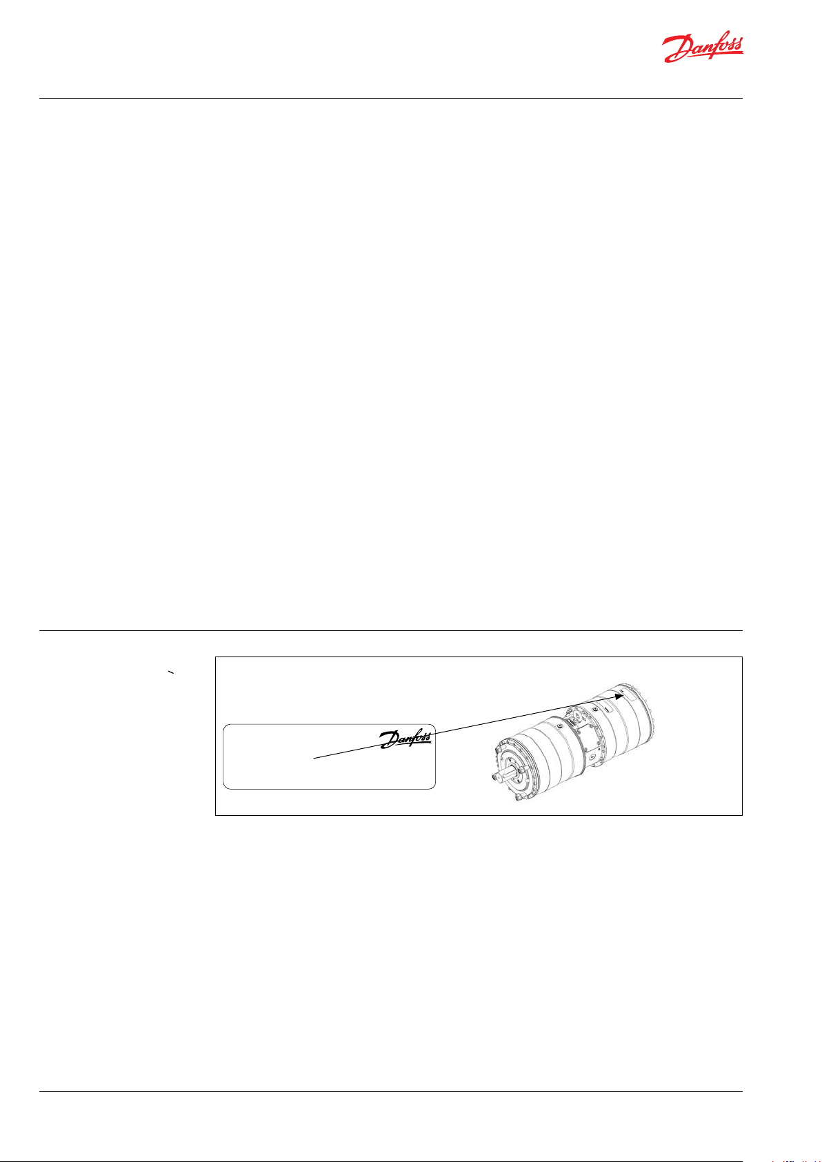
1. Identication
7. Service and warranty...................................................................11
PUMP
Type APP 78
Code no. 180BXXXX
Serial no. XXXXXX08-XXX
MADE IN DENMARK
Danfoss A/S, 6430 Nordborg, Denmark
2 | © Danfoss | DCS (im) | 2021.05 AN220686503013en-000901 | 180R9368 | 521B1392
Page 3
Instruction | APP Pump Instruction APP 53-92
2. System design
The design of the system must ensure that
self-emptying of the pump during standstill is
avoided.
The inlet pressure of the pump must never
exceed the outlet pressure. This may typically
occur in boosted or open-ended systems with
direct water supply.
2.1 Open-ended systems with direct water
supply
Axial piston pumps require a certain inlet
pressure to perform as intended. Please nd min.
required feed pressure in the pump data sheet.
Please also note that feed pressure must not
exceed 5 barg (72.5 psig).
2.2
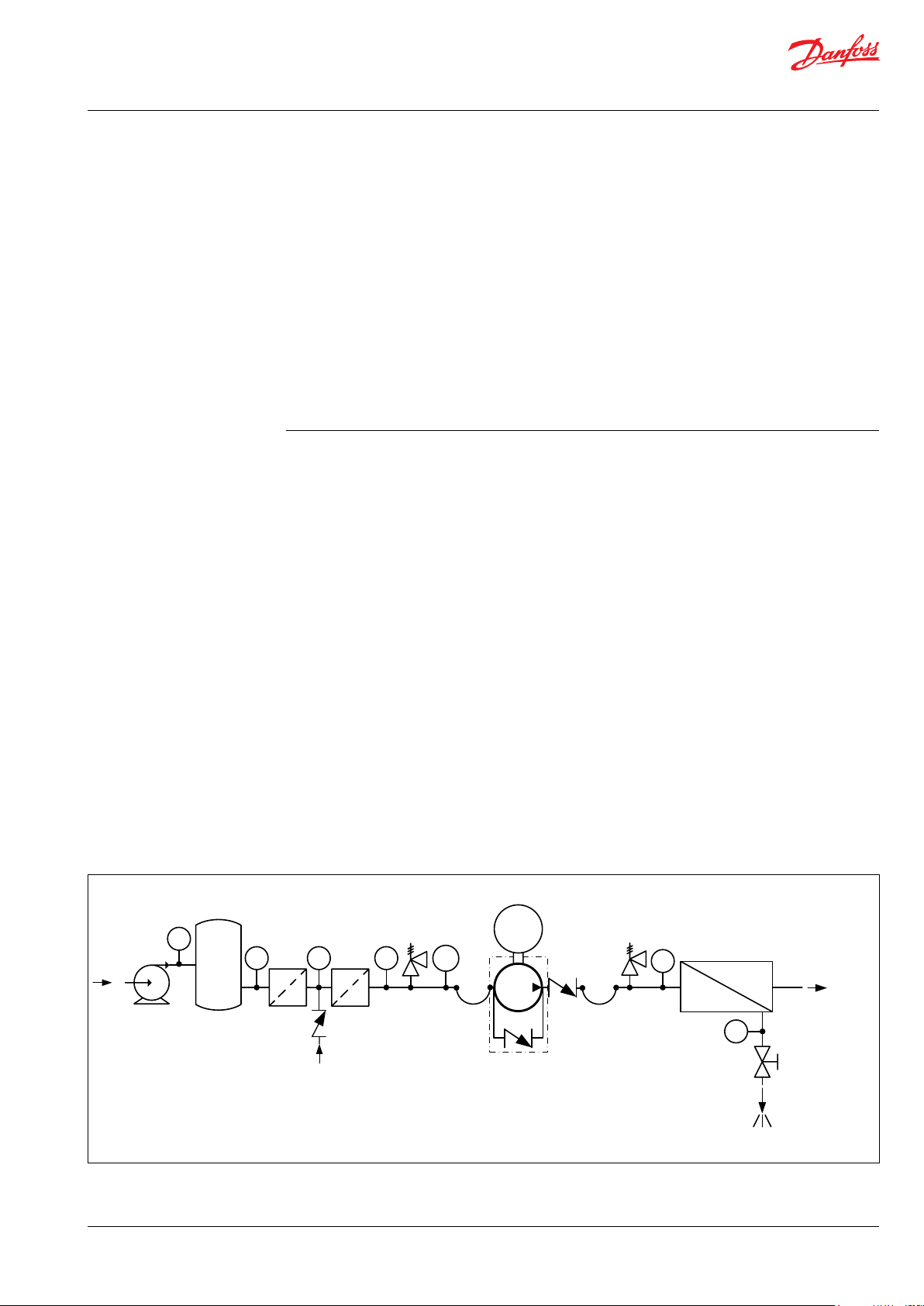
Preferred RO system design without ERD
1. Dimension the inlet line to obtain minimum pressure loss (large ow, minimum
pipe length, minimum number of bends/
connections, and ttings with small
pressure losses).
2. Place an inlet lter (1) in front of the APP
pump (2). Please consult Danfoss lter data
sheet for guidance on how to select the
right lter. Thoroughly clean pipes and
ush system prior to start-up.
3. Place a monitoring pressure switch (3) set
at min. inlet pressure between lter and
pump inlet. The monitoring switch must
stop the pump at pressures lower than
minimum pressure.
4. Use exible hoses (4) to minimize vibrations
and noise.
5. In order to eliminate the risk of damage
and cavitation, a positive pressure at the
inlet (5) is always to be maintained at min.
inlet pressure and max. inlet pressure.
To protect the pump from being damaged by
peaks of high-pressure in case the pump stops
momentarily, it is required to mount a lowpressure relief valve on the inlet line.
Note: The inlet connection must be properly
tightened, as possible entrance of air will cause
cavitation.
It is recommend to install safety valve or a
pressure relief valve (9) in order to avoid
high-pressure peaks in case the pump stops
momentarilly or is spinning backwards.
6. For easy system bleeding and ushing, a
bypass non-return valve (6) is integrated in
the APP pump.
7. A non-return valve (7) in outlet can be
installed in order to avoid backspin of the
pump. The volume of water in the membrane vessel works as an accumulator and
will send ow backwards in case of the
pump stops momentarily.
8. A safety valve or a pressure relief valve (8)
can be installed in order to avoid system
damage as the Danfoss APP pump creates
pressure and ow immediately after startup, regardless of any counter pressure.
Note: If a non-return valve is mounted in the
inlet line, a low-pressure relief valve is also
required between non-return valve and pump
as protection against high-pressure peaks.
Feed
Media filter
PI
PI
PI PI
Fresh water
permeat flush
PT
M
PI
PI
Brine
Permeate
© Danfoss | DCS (im) | 2021.05 AN220686503013en-000901 | 180R9368 | 521B1392 | 3
Page 4
Instruction | APP Pump Instruction APP 53-92
2.3 Preferred RO system design with ERD
For P&ID of a setup with an iSave, please see the
iSave® Data sheet 521B1378
2.4 Preferred RO system design with pumps
and ERDs in parallel
For systems with Danfoss pumps and ERDs in
parallel, please see our publication 180R9354,
Guideline for Parallel-coupled pumps and ERD.
2.5 Reversible pumps
If exposed to high-pressure in the outlet while
the electric motor is not energized, the pumps
may start spinning backwards. This will not harm
the pumps as long as the pressure in the inlet
does not exceed the max. pressure peak of
10 barg(145 psig).
If a non-return valve is mounted in the inlet line,
a low-pressure relief valve is required as protection against high-pressure pulses and high-pressure in general.
Alternatively a high-pressure check valve can be
mounted in the pump discharge line to prevent
the pump from reversing.
The setup of “open-end system” ensures that the
inlet pressure does not exceed 10 barg (145 psig),
when a nonreturn valve is mounted in the inlet.
2.6 General comments
A good ltration is vital to ensure a long and
trouble-free life of the pump.
As water has very low viscosity, the APP pumps
have been designed with very narrow clearance
in order to control internal leakage rates and
improve component performance. Therefore it is
important that the inlet water is ltered properly
to minimize the wear of the pump.
The main lter must have a ltration eciency of
99.98% at 10 μm. We recommend to use
precision depth lter cartridges rated 10 μm abs.
β10 ≥ 5000 (equivalent to a ltration eciency of
99.98%). Bag lters and string wounded lter
cartridges typically have only 50% ltration
eciency. This means that for each 100,000 particles reaching the lter, 50,000 particles pass
through it compared to only 20 particles in a
lter with an eciency of 99.98%.
For more information on the importance of
proper ltration, please see our data sheet
521B1009 on “Filtration”, which also will provide
you with an explanation of ltration denitions
and a guidance on how to select the right lter.
Monitoring
It is recommended to continuously monitor the
following conditions:
• Filter clogging
• Pressure (inlet- and outlet side of the
pump)
3. Building up the
pump unit with BoWex
coupling
3.1 Assembly of the coupling
We recommend to inspect bores, shaft,
keyway and feather key for dimensional
accuracy before assembly.
Heating the hubs lightly (approx. 80 °C)
allows for an easier mounting on the
shaft.
Please pay attention to the ignition risk
in potentially explosive atmospheres!
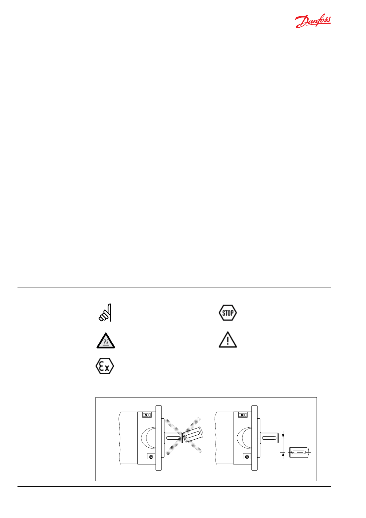
3.2 Alignment between the motor and
pump shaft
Touching the heated hubs causes
burns.
Please wear safety gloves.
With the assembly please make sure
that the spline of the hub is fully covered by the internal spline of elastomer (please observe mounting dimensions L
may cause damage to the coupling.
). Disregarding this advice
coupling
max. 0. 5 mm
max. 0.02 in ch
4 | © Danfoss | DCS (im) | 2021.05 AN220686503013en-000901 | 180R9368 | 521B1392
Page 5

Instruction | APP Pump Instruction APP 53-92
3.3 Overall assembly with coupling
BoWex-ELASTIC®, type HEW compact
Danfoss recommends to use a Bowex Elastic HEW
Compact Coupling.
See the Coupling Manual from BoWex.
1: Bolts 190 Nm ± 10
2: Nuts 100 Nm ± 10
3: Torque see ta ble
Component
Thread size M5 M6 M8 M10
Torque [Nm] 2 4.8 10 17
Quantity Description
1 1 Elastomer part
2 1 Hub
4 1 Coupling ange
5
10
7 2
Cap screws
DIN EN ISO 4762
Setscrews
DIN EN ISO 4029
© Danfoss | DCS (im) | 2021.05 AN220686503013en-000901 | 180R9368 | 521B1392 | 5
Page 6

Instruction | APP Pump Instruction APP 53-92
3.3.1 Mounting
1. Mount the coupling ange (component 4)
in front of the elastomer part (component
1) and screw the components together
with a tightening torque of 120 Nm.
Lubricate inside the coupling hubs (not the
shafts).
If used in potentially explosive atmospheres the setscrews to fasten the hubs
as well as all screw connections must be
secured against working loose additionally, e.g. conglutinating with Loctite
(average strength).
Please observe the manufacturer’s
instructions regarding the use of adhesives. Do not apply glue on the rubber
surfaces.
2. Mount the bell housing on pump. Secure
nuts with the right torque.
3. Push the coupling part all the way down to
the shoulder of
with right torque on the locking screws.
Measure the distance “a” from the end of
the bell housing to the end of the toothing
of the coupling.
4. Mount the coupling on motor shaft
without using hammer. If needed then
polish motor shaft/key and inside coupling
hub.
5. On the motor shaft position the coupling
so that the length from the end of the
coupling to the end of the motor flange is
“b= a+32.5 mm” ± 2 mm.
6. Secure coupling on motor shaft with the
right torques on the locking screws.
7. Connect carefully pump/bell housing to
motor. Turn motor shaft so coupling tooths
can interact.
8. Mount motor flange bolts to bell housing
and tighten with the right torque.
9. Check coupling space. The pump coupling
should be in a position so there is still
3-7 mm space.
If alternative mounting is desired, please contact
Danfoss High Pressure Pumps.
Please take care to observe the recommended
length tolerances of the chosen coupling, as an
axial force on the pump will damage the pump.
the pump shaft and secure
b = a + 32.5 mm ± 2 mm
6 | © Danfoss | DCS (im) | 2021.05 AN220686503013en-000901 | 180R9368 | 521B1392
Page 7

Instruction | APP Pump Instruction APP 53-92
3-5 mm
[0.12-0.20 inch]
3.4 Direction of rotation
Is indicated by an arrow engraved in the ange
of the pump.
3.5 Orientation
APP 53-92 can be mounted/orientated in steps of
The opening characteristics of the valve must not
result in peak pressures higher than 100 barg
(1450 psig).
The valve should be placed as close to the pump
as possible.
45 degrees. Please see Data sheet 521B1340.
We recommend to install exible soft hoses both
3.6 Protection from too high pressures
in the inlet and outlet lines.
The pump should be protected against too high
pressure by means of a safety valve or a pressure
relief valve.
The valve outlet must not be connected directly to the pump suction line.
It must be connected directly to the drain.
Outlet
Outlet Inlet
4. Building up the
pump unit with jaw
coupling
D
Inlet
A: Elastic coupling
B: Bell housing
C: Motor shaft
D: Pump ange
4.1 Mounting
1. Mount the coupling ush with the pump
shaft end or maximum 1 mm oset from
the pump shaft end. Ensure an air gap
between coupling parts of 3-5 mm (0.12-0.2
inch).
2. Mount the bell housing on pump. Secure
nuts with the right torque.
3. Measure the longest distance “A” from top
of bell housing to the button of coupling
claw.
IMPORTANT
When using jaw coupling it is critiacal
that the recommended measurements are kept.
max. 0. 25 mm
max. 0. 01 inch
4. Mount the coupling on motor shaft. Ensure
the coupling and motor ange are not in
contact with each other.
5. Measure from motor ange to the top of
the coupling. That measurement “B” shall
be 3-5 mm (0.12-0.2 inch) shorter than the
measurement “A”.
(“A” and “B” can be found on the next
page).
© Danfoss | DCS (im) | 2021.05 AN220686503013en-000901 | 180R9368 | 521B1392 | 7
Page 8

Instruction | APP Pump Instruction APP 53-92
Bolts and nuts
torque
6. Adjust respectively, verify the measurement, and secure both couplings with the
right torques on the locking screws (see
coupling operation & mounting instruction).
7. Mount the elastic gear ring and mount the
bell housing/pump on the motor. After
mounting it must be possible to move the
elastic gear ring 3-5 mm (0.12 - 0.2 inch)
axial “C”. The check can be done through
the inspection hole of bell housing. Secure
ange bolts with the right torque.
1: Bolts 100 Nm ± 10
2: Nuts 100 Nm ± 10
3: Torque se table below
75 Nm ± 5 Nm
1
2
C
If alternative mounting is desired, please contact
Danfoss High Pressure Pumps.
Choose proper tolerances to ensure an easy
mounting of the elastic coupling without use of
tools.
Please take care to observe the recommended
length tolerances of the chosen coupling, as an
axial force on the pump will damage the pump.
3
4.2 Connections
To prevent stray current corrosion we recommend grounding of the pump and all other parts
in the system.
All parts in the system must be electrical
potential equalized to a single reference point
(grounding point).
It is recommended that the electrical resistance
in the grounding cable is equal to or below 0.25
Ohm towards the grounding point.
Thread
size
Torque
[Nm]
M5 M6 M8 M10
2 4.8 10 17
8 | © Danfoss | DCS (im) | 2021.05 AN220686503013en-000901 | 180R9368 | 521B1392
Page 9

Instruction | APP Pump Instruction APP 53-92
5. Initial start-up
1. Flush inlet line before connecting the
pump, to remove possible impurities from
pipes, hoses etc.
2. Connect pump inlet to inlet line and ush
the pump for 5 min. by means of the
internal ushing valve, to remove possible
impurities from pipes, hoses etc.
3. Loosen top bleeding plug (see item 3.5)
using an allen key (only plugs with internal
hexagon sockets). Retighten the plug,
when water appears from the bleeding
plug.
4. Make sure that the direction of rotation of
the electric motor corresponds to the direction of rotation of the pump, show on the
pump ange.
5. Now the pump is ready for start-up.
WARNING
Make sure that the direction of rotation of the
electric motor corresponds to the direction of
rotation of the pump.
Otherwise the pump will be damaged if a
check valve is placed between pump and feed
pump.
O
I
Internal
ushing
valve
© Danfoss | DCS (im) | 2021.05 AN220686503013en-000901 | 180R9368 | 521B1392 | 9
Page 10

Instruction | APP Pump Instruction APP 53-92
6. Operation
6.1 Te mperat u re
Fluid temperature:
Min. +2°C to max. +50°C
(Min. +35.6°F to max. +122°F)
Ambient temperature:
Min. +2°C to max. +50°C
(Min. +35.6°F to max. +122°F)
In case of lower operating temperatures, please
contact Danfoss High Pressure Pumps.
NaCl vs. temperature
º
C
80
Duplex
70
60
50
316L
40
The chart below illustrates the corrosive
resistance of dierent types of stainless steel
related to NaCl concentration and temperature.
The APP water pump is made of Duplex and
Super Duplex.
If the water pump is operated above the Super
Duplex line, always ush water pump with fresh
water at operation stop in order to minimize the
risk of crevice corrosion.
Super Duplex
30
20
100
1000
160 1600
6.2 Pressure
The inlet pressure shall be min. 2 barg (30 psig)
and max. 5 barg (72.5 psig). At lower pressures
the pump will cavitate, resulting in damage of
the pump.
Max. inlet pressure peak (e.g. in case the pump
stops momentarily) up to 10 barg (145 psig) are
acceptable.
Max. pressure on the pump’s outlet line shall be
limited at 80 barg (1160 psig) continuously.
For APP 86 min. inlet pressure shall be 2.5 barg
(36 psig) and max. outlet pressure shall be
70 barg (1015 psig).
For APP 92 min. inlet pressure shall be 3.5 barg
(50 psig) and max. outlet pressure shall be
70 barg (1015 psig).
-
10 000
16000
6.3 Dry running
When running, the pump must always be
connected to the water supply in order to avoid
damage if it should run dry.
6.4 Disconnection
If the inlet line is disconnected from the water
supply, the pump will be emptied of water
through the disconnected inlet line.
When starting up again, follow the bleeding
procedure described under section 4: Initial
start up.
100 000
160000
CI
ppm
NaCI
ppm
Note: The pump unit should include a pressure
gauge on the high-pressure side.
10 | © Danfoss | DCS (im) | 2021.05 AN220686503013en-000901 | 180R9368 | 521B1392
Page 11

Instruction | APP Pump Instruction APP 53-92
6.5 Storage
Storage temperature:
Min. -40°C to max. +70°C
(Min. -40°F to max. +158°F)
When preparing the pump for long-term storage
at temperatures below the freezing point, ush
the pump with an anti-freeze medium type
monopropylene glycol to prevent internal
corrosion or frost in the pump.
For further information on anti-freeze media,
please contact Danfoss High Pressure Pumps.
Recommended procedure:
1. Disconnect the water supply to the pump.
2. Through the lower bleeding plug, empty
the pump housing of water and close it
again.
3. Connect the pump to a tank containing
anti-freeze additive. Connect a hose to the
inlet port of the pump and via another
hose return the ow from the outlet port to
the tank with antifreeze additives.
4. Quickly start and stop the pump. Make
sure that the pump does not run dry.
The pump is now protected against
internal corrosion and frost.
Storage:
Storage of pump that have been in operation:
For shorter periods of storage ush the pump
with permeate by rotating the pump for 10 sec.
empty permeate and store.
For long term storage (more than 2 months)
Danfoss recommends servicing the product and
clean any biological growth of the surfaces. Store
the pump without water inside.
7. Service and warranty
Warranty
Danfoss APP pumps are designed for long
operation, low maintenance and reduced
lifecycle costs.
Provided that the pump has been running
according to the Danfoss specications, Danfoss
guarantees 8,000 hours service-free operation,
however, max. 18 months from date of
production.
If Danfoss recommendations concerning
system-design are not followed, it will strongly
inuence the life of the APP pumps.
Other factors that aect pump performance and
lifetime include:
- Insucient ltration
- Insucient bleeding and venting
- Running the pump at speed outside
specications.
- Supplying the pump with water at
temperature higher than recommended.
- Running the pump at inlet pressure outside
specications.
- Running the pump at outlet pressure
outside the specications.
- Wrong direction of rotation.
Pump shutdown:
The APP pumps are made of Duplex/Super
Duplex materials with excellent corrosion
properties. It is, however, always recommended
to ush the pump with freshwater when the
system is shut down.
When stopping the pump for more than 1 day
ush the pump with permeate by rotating the
pump for 10 sec. Flushing through the ashing
valve of the pump without rotating the pump is
not enough for cleaning the inside of the pump.
The pump can be ushed with biocide like the
membranes. The biocide must be compatible
with the materials used in our pump (materials
can be found in the parts list in the Service guide
and Operating manual).
Repair
In case of irregular function of the APP pump,
please contact Danfoss High Pressure Pumps.
Maintenance
After 8,000 hours of operation it is strongly
recommended to inspect the pump and change
any worn parts, e.g. pistons and shaft
seal. This is done in order to prevent a potential
breakdown of the pump. If the parts are not
replaced, more frequent inspection is
recommended according to our guidelines.
© Danfoss | DCS (im) | 2021.05 AN220686503013en-000901 | 180R9368 | 521B1392 | 11
Page 12

Danfoss A/S
High Pressure Pumps
DK-6430 Nordborg
Denmark
© Danfoss | DCS (im) | 2021.05
AN220686503013en-000901 | 180R9368 | 521B1392 | 12
 Loading...