

Page 1
Operating guide
User manual
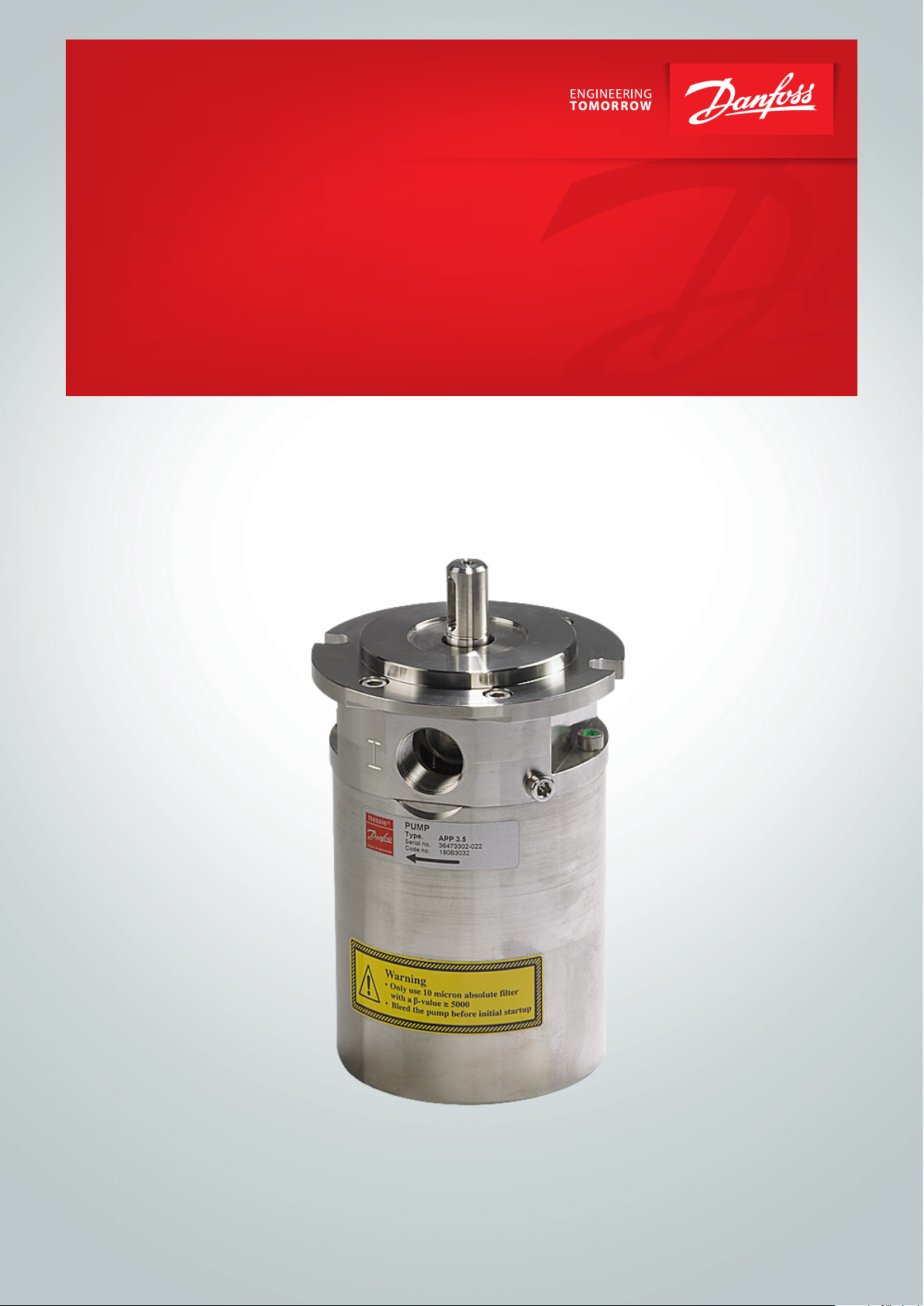
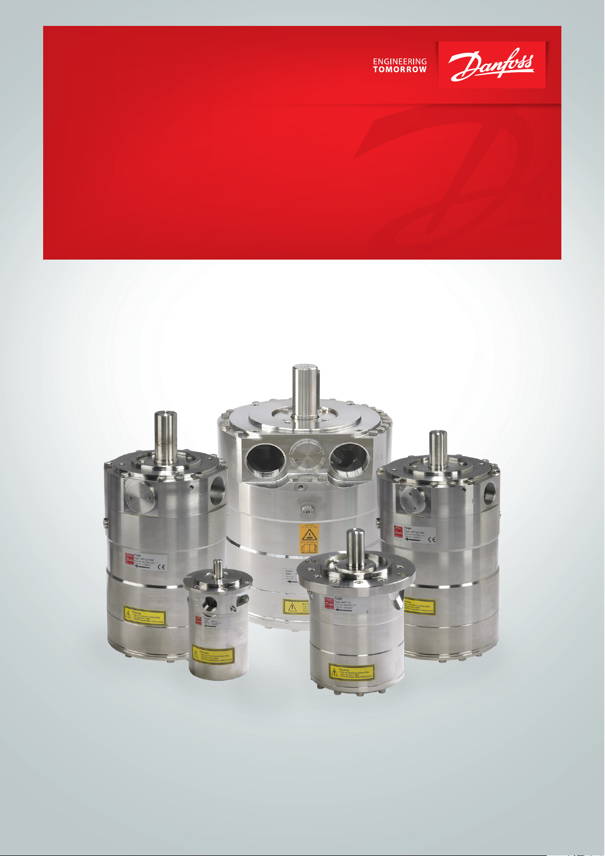
APP pumps
Installation, Operation and
APP 1.5 - 3.5
Installation, Operation and
Maintenance Manual
Maintenance Manual
APP pumps (APP 1.5-3.5)
APP 1.5-3.5
hpp.danfoss.com
ro-solutions.com
Page 2

Operating guide | APP 1.5-3.5 pumps
Table of Contents Contents
Table of Contents ..................................................................................2
Validity .........................................................................................4
1. Introduction ............................................................................5
1.1 General.................................................................................5
1.2 Symbols ................................................................................5
1.3 Manufacturer and customer service address .............................................6
1.4 Country specific information ............................................................6
1.4.1 United Kingdom ........................................................................6
2. Safety ..................................................................................6
2.1 General information.....................................................................6
2.2 Preferred system design.................................................................6
2.3 Commissioning and servicing the unit ...................................................7
2.4 Adhere to the following important points ...............................................7
2.5 In case of doubt .........................................................................7
3. Technical data ..........................................................................7
3.1 Approved applications and operational limits for the pumps .............................7
3.2 Application range .......................................................................7
3.3 Electric motor data......................................................................7
3.4 Noise and vibration .....................................................................7
3.5 Dimension drawings ....................................................................7
3.6 Space requirement......................................................................7
3.7 Filtration................................................................................8
3.8 Properties of water ......................................................................8
3.9 Air bubbles .............................................................................8
3.10 Chemicals...............................................................................8
4. Arrival inspection, transportation, handling, lifting and storage ..........................8
4.1 Arrival inspection .......................................................................8
4.2 Warning ................................................................................8
4.3 General safety information ..............................................................8
4.4 Transport and handling .................................................................8
4.5 Return to supplier .......................................................................9
4.6 Storage .................................................................................9
5. Installation and commissioning.........................................................10
5.1 Important dimensions .................................................................10
5.2 Cleanliness.............................................................................10
5.3 Fluid temperature......................................................................10
5.4 Electrical data..........................................................................10
5.5 Local regulations.......................................................................10
5.6 Pre mounting checklist, based on Danfoss preferred system design .....................11
5.7 Lifting and positioning.................................................................11
5.8 Mount the different equipment ........................................................11
5.9 Electrics ...............................................................................11
5.10 Instrumentation .......................................................................11
5.11 Connections ...........................................................................11
5.12 Ensure free flow .......................................................................12
5.13 Verify setting of safety/relief valves .....................................................12
5.14 Flush the pump ........................................................................12
5.15 Bleed and remove air from the pump...................................................12
5.16 Verify direction of rotation .............................................................12
5.17 Commissioning ........................................................................12
5.18 Check the filter condition...............................................................12
5.19 Instruct operator and maintenance personnel ..........................................12
6. Operation of pump unit ...............................................................13
6.1 General safety information.............................................................13
6.2 What to listen and look for .............................................................13
2
180R9267 | AQ291128576527en-000901 IOM APP 1.5-3.5 Pumps | 12.2021
Page 3

Operating guide | APP 1.5-3.5 pumps
7. Maintenance and service of the pump unit .............................................13
7.1 General safety information .............................................................13
7.2 Service and inspection interval for the pump ...........................................13
7.3 Shut down of the system ...............................................................13
7.4 Disassembling and assembling the pump unit ..........................................14
7.5 Assembling the pump unit .............................................................14
7.6 Procedure for mounting the pump onto the electric motor..............................14
7.7 Getting the pump unit back into operation .............................................14
7.8 Storage of the pump ...................................................................14
8. Troubleshooting and scrapping criteria .................................................15
8.1 General safety information .............................................................15
8.2 Operational conditions which can cause pump failures..................................15
8.3 Mechanical failure......................................................................15
8.4 Electrical failure........................................................................15
8.5 Responsibility..........................................................................15
8.6 Scrapping criteria ......................................................................15
Appendices ......................................................................................17
Table of Contents .................................................................................18
1. Data sheet for APP 1.5-3.5 (AI274333290009en-000701) .................................19
2. Pump instruction APP 1.5-3.5 (180R9065) ...............................................33
3. IOM Electric motors (180R9230)..........................................................41
4. Recommended service intervals for APP pumps (AX290239527130en-000201)...........47
5. Parts list for APP 1.5-3.5 (AX274346749037en-000501)...................................51
6. Trouble shooting guide for APP, APP S and APP S 674 pumps ............................61
7. Right and wrong (180R9042) ...........................................................73
180R9267 | AQ291128576527en-000901 IOM APP 1.5-3.5 Pumps | 12.2021
3
Page 4
Operating guide | APP 1.5-3.5 pumps
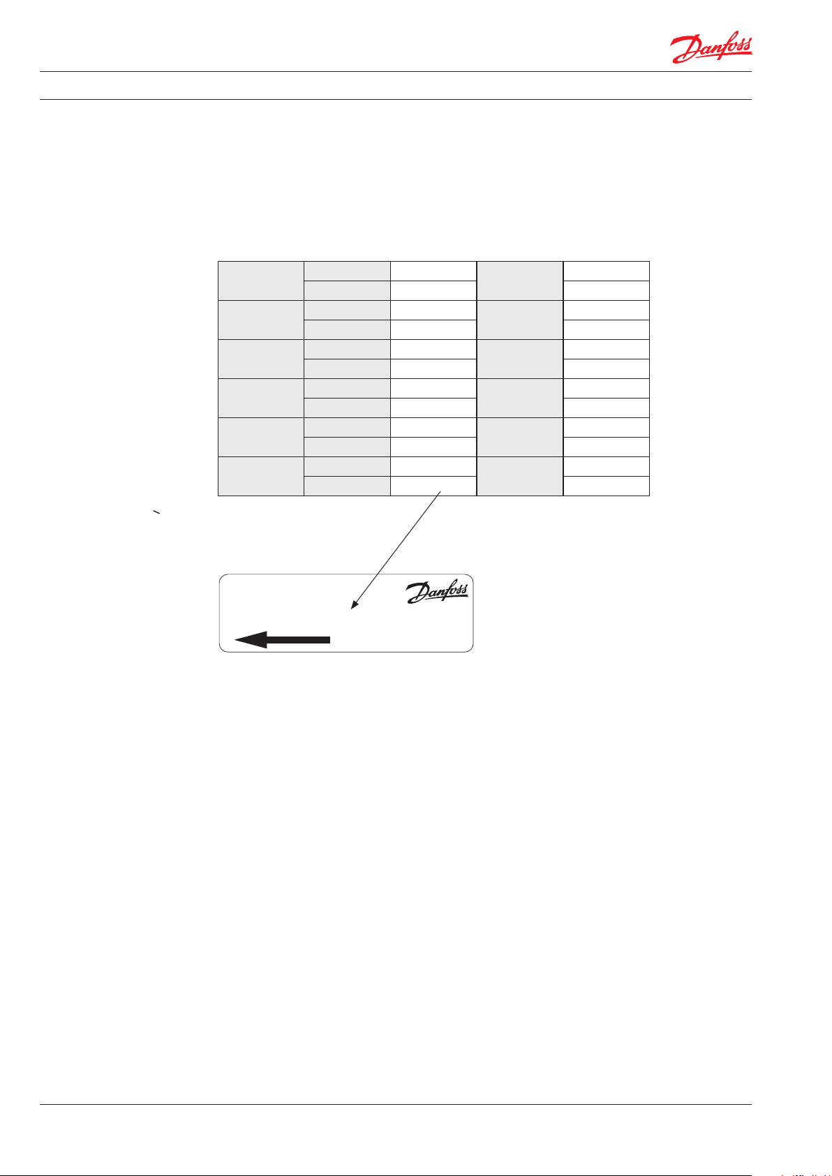
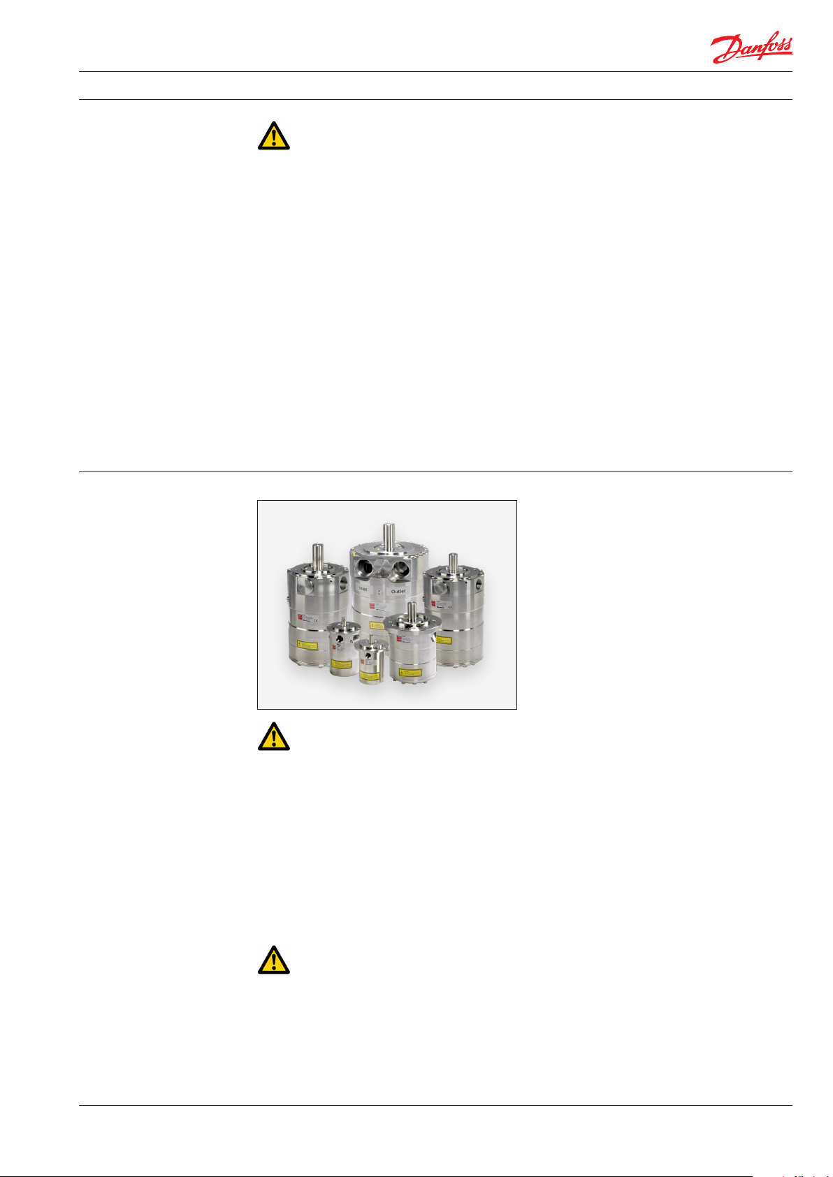
Validity
This manual is valid for APP pumps both non
ATEX and ATEX certified versions. An
ATEX certified pumps are indicated by Ex
in the designation - example APP 3.5 Ex.
APP 1.5
APP 1.8
APP 2.2
APP 2.5
APP 3.0
APP 3.5
Code no. 180B30 43
Serial no. XXXXXX02-XXX XXXXXX02-XXX
Code no. 180B30 44
Serial no. XXXXXX02-XXX XXXXXX02-XXX
Code no. 180B30 45
Serial no. XXXXXX02-XXX XXXXXX02-XXX
Code no. 180B30 46
Serial no. XXXXXX02-XXX XXXXXX02-XXX
Code no. 180B3030
Serial no. XXXXXX02-XXX XXXXXX02-XXX
Code no. 180B3032
Serial no. XXXXXX02-XXX XXXXXX02-XXX
In case the pump delivered is ATEX certified, the
additional ATEX instruction must also be read.
APP 1.5 Ex
APP 1.8 Ex
APP 2.2 Ex
APP 2.5 Ex
APP 3.0 Ex
APP 3.5 Ex
On request
On request
180 B3145
180 B3146
180B3130
180B3132
PUMP
Type APP 2.2
Code no. 180B3045
Serial no. XXXXXX02-XXX
MADE IN DENMARK
Danfoss A/S, 6430 Nordborg, Denmark
The serial number is referring to the Serial no. on
the product label. The digits shown (03) indicate
the version number of the pump.
This documentation is compatible with previous
pump versions.
4
180R9267 | AQ291128576527en-000901 IOM APP 1.5-3.5 Pumps | 12.2021
Page 5
Operating guide | APP 1.5-3.5 pumps
1. Introduction
1.1 General
The APP pumps and pump units are manufactured by Danfoss A/S, and are sold and marketed
by a net of authorized distributors world wide.
This manual contains the necessary instructions
for the installation, operation and service of the
pumps used in a Sea Water Reverse Osmosis
(SWRO) system or Brackish Water Reverse
Osmosis (BWRO) system.
In case the pump delivered is ATEX certified, the
additional ATEX instruction must also be read.
The APP pumps must not be used for other
purposes than those recommended and
specified without first consulting your local
pump distributor.
Use of the pump in other applications that are
not suitable for the pump unit can cause
damages to the pump unit, with risk of personal
injury.
• If any changes are made without written
approval the warranty will automatically
become void.
It is important that these instructions are
always available to the personnel concerned.
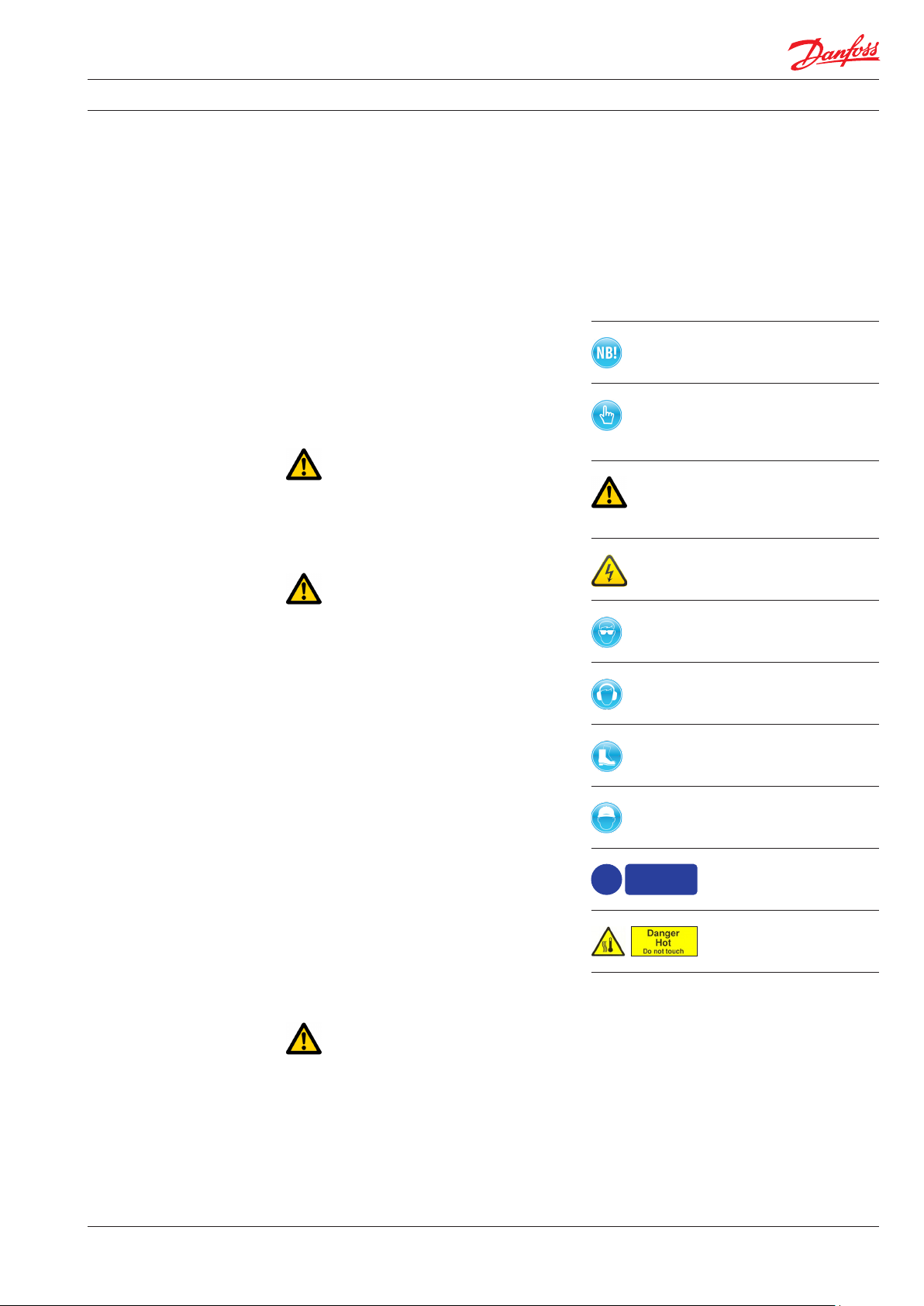
1.2 Symbols
Indicates something to be noted by the
reader
Indicates a situation which will or could
result in damage to the pump and its
function
Indicates a situation which will or could
result in personal injury and/or damage
to the pump
Electrical hazard - Indicates a high-
voltage warning
All personnel being responsible for operation
and maintenance of the pump unit must read
and fully understand these instructions,
especially the section “Safety”, before:
• Transportation of the pump unit
• Lifting the unit
• Installing the pump unit
• Connecting the pump unit to the water
system
• Connecting the electric motor and instrumentation
• Commissioning the unit
• Servicing the pump unit, mechanical and
electrical parts
• Decommissioning the pump unit
The pump must always be installed and used in
accordance with existing national/local
sanitary, safety regulations and laws.
It is the responsibility of the safety officer or
the chief operator to assure compliance with all
local regulations that are not taken into
account in this manual.
Safety glasses required
Hearing protection required
Safety shoes required
Safety helmet required
!
Protective
garments
must be wor n
Protective garments
must be worn
Danger HOT.
Do not touch
Changing the pumps’ or pump units’ operational limits and hardware:
• Changes to the delivered pump or motor
pump unit may only be done with a written
approval from Danfoss High Pressure Pumps.
• Operation outside the Danfoss specifications
requires a written approval from Danfoss
High Pressure Pumps.
180R9267 | AQ291128576527en-000901 IOM APP 1.5-3.5 Pumps | 12.2021
5
Page 6
Operating guide | APP 1.5-3.5 pumps
2. Safety
1.3 Manufacturer and customer service
address
Danfoss A/S
Danfoss High Pressure Pumps
Nordborgvej 81,
DK-6430 Nordborg
Denmark
Telephone: +45 7488 4024
Fax: +45 7445 3831
Email: highpressurepumps@danfoss.com
Homepage: hpp.danfoss.com
2.1 General information
Dangers that can arise from not following the
instructions:
When the pump or pump unit is managed by
untrained personnel, there is a danger of:
• Death or fatal injuries
• Costly damages and claims
Your local Danfoss pump distributor can be
found on our homepage.
Data sheets and instructions on all accessories
are available on hpp.danfoss.com
1.4 Country specific information
1.4.1 United Kingdom
UK importer:
Danfoss Ltd.
22 Wycombe End
HP9 1NB Beaconsfield
United Kingdom
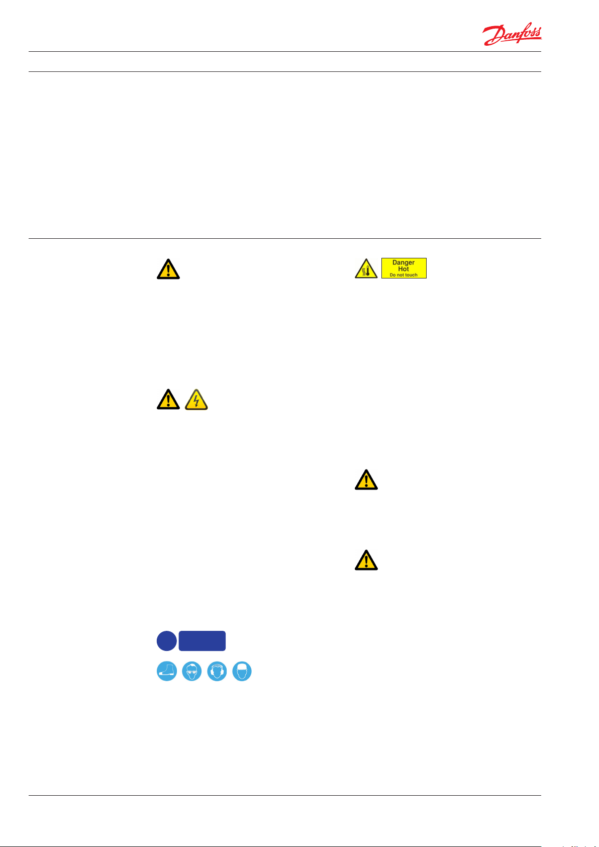
Under certain operational conditions the surface
of the pump can be above 60°C / 140°F. Under
these conditions the pump must be labelled with
a “Danger Hot” sign.
When using an electric motor, the motor must
always be supplied with adequate cooling
ventilation.
When using an electric motor together with a
VFD, the motor must be designed for operation
with a VFD.
All electrical installation work must only be
carried out by authorized personnel in
accordance with EN60204-1 and/or local
regulations.
It is recommended to install a lockable circuit
breaker to avoid inadvertent starting and/or
electrical hazard. The lockable circuit breaker
must be used during installation, operation and
maintenance.
It is recommended to place a local safety switch
nearby the pump, enabling service personnel to
cut power for the electric motor.
Protect the motor and other electrical equipment from overloads with suitable equipment.
In case the pump delivered is ATEX certified, the
additional ATEX instruction must also be read.
Protective
garments
!
must be wor n
Always wear suitable safety clothing when
handling the pump.
When working near the pump system, safety
shoes, safety glasses, hearing protection and
safety helmet must always be worn.
VFD operation may increase the temperature
inside the electric motor if the motor is not
designed for VFD operation. This can damage
the motor and cause unintended breakdown.
Before start-up, the settings for all protective
devices, such as sensors/switches and safety
valves must be verified and free flow from safety
valves must be ensured.
All pipe and hose connections must be stressfree mounted, securely fastened to the pump
and well supported. Improper installation will or
can result in personal injury and/or damage to
the pump.
Use of this manual does not relieve operation
and maintenance personnel of the responsibility of applying good judgment when operating
and maintaining the pump and its components.
2.2 Preferred system design
Danfoss recommends to build systems with a
high degree of safety. Danfoss preferred system
design and P&ID are found in appendix 1, Data
sheet, and appendix 2, Instruction.
6
180R9267 | AQ291128576527en-000901 IOM APP 1.5-3.5 Pumps | 12.2021
Page 7
Operating guide | APP 1.5-3.5 pumps
It is always the system builder´s responsibility
that the system design does not cause any kind
of hazard and is adapted to local regulations and
standards.
• Do not try to lift the pump unit manually;
most of the pumps weigh more than
20 kilos, see specific weight for the pump
in the appendix 1, Data sheet.
• Always bleed the pump prior to initial
Proper installation, proper start up and shutdown devices as well as high-pressure protection
equipment is essential.
start-up.
• Do not mount the pump without the bell
housing and a flexible coupling.
• Do not try to start the unit before the
system components are mounted, bleeded
2.3 Commissioning and servicing the unit
It is recommended that commissioning and
servicing are carried out by a minimum of two
people, where one is acting as a supervisor.
and adjusted.
• Flush the system throughly before
connecting the pump or pump unit.
• Check rotation direction of the motor
before mounting the pump.
2.4 Adhere to the following important
points
2.5 In case of doubt
Please contact Danfoss A/S in case of doubt.
• Before using the pump/pump unit it is very
important to read and understand this user
Contact information is listed in section 1.3,
Manufacturer and customer service address.
manual.
3. Technical data 3.2 Application range
See appendix 1, Data sheet.
3.1 Approved applications and operational
limits for the pumps
The pump and the pump units are designed for
the use in a Sea Water Reverse Osmosis (SWRO)
or Brackish Water Reverse Osmosis (BWRO)
systems and Brackish Water Reverse Osmosis
(BWRO) system.
The APP pumps must not be used for other
purposes than those recommended and
specified without first consulting your local
pump distributor.
3.3 Electric motor data
See recommended motor in appendix 1, Data
sheet or appendix 3, IOM for motors. The motors
mentioned are the most common used motors
by Danfoss High Pressure Pumps.
3.4 Noise and vibration
Noise level for a pump unit with a ”standard”
motor measured according to EN ISO 3744: 2010,
see appendix 1, Data sheet. Possibilities to
reduce noise and vibration are described in the
same Data sheet.
3.5 Dimension drawings
Dimensions of the different pumps can be found
in appendix 1, Data sheet.
3.6 Space requirement
When doing service or replacing the complete
pump unit, it is recommended to have sufficient
space available around the pump in order to
ensure easy access. Sufficient space means at
least 1 meter/40 inches around the pump. When
working with high pressures, it is important to
have the right space available around the pump
as stated in the safety requirements.
Use of the pump in other applications not
suitable for the pump unit can cause damages
to the pump unit, with risk of personal injury.
For system integration of the pump, please see
appendix 1, Data sheet and appendix 2,
Instruction.
180R9267 | AQ291128576527en-000901 IOM APP 1.5-3.5 Pumps | 12.2021
7
Page 8
Operating guide | APP 1.5-3.5 pumps
3.7 Filtration
(10µm absolute [ß10 ≥ 5000])
Requirements are specified in appendix 1, Data
sheet and in appendix 2, Instruction.
Danfoss recommends not to build a filter bypass
function or to use filters with an integrated
bypass. If the above recommendation is not
followed the warranty for the pump will
automatically become void.
It should be possible to monitor the condition of
the filter via the differential/delta pressure across
the filter.
Using insufficient filtration or a filter bypass
can cause a failure or decreased service life of
the pump.
3.8 Properties of water
It is recommended NOT to use the pumps in feed
water concentrations higher than 50,000 ppm
TDS without consulting your local Danfoss pump
distributor.
3.9 Air bubbles
Large bubbles in a pressurised RO system can
result in damage to piping, equipment and the
pump.
All air must be bleeded from both the lowpressure and high-pressure side before the RO
system is pressurised. Special consideration
should be given in order to minimize air bubbles
in the feed flow. Air bubbles can cause cavitation.
3.10 Chemicals
The pump should not be exposed to any
chemicals as it can result in damage to piping,
equipment and internal parts in the pump.
4. Arrival inspection,
transportation,
handling, lifting and
storage
4.1 Arrival inspection
The pump is packed in a cardboard or wood box
with plugs in the port connections to protect the
pumps from damage during transportation.
When the shipment has arrived it is important to
check the pump for any damages. The name
plate/type designation must be in accordance
with the delivery note and your order.
In case of damage and/or missing parts, a report
should be documented and presented to the
carrier at once.
4.2 Warning
Before any lifting operation is performed,
environmental conditions must be taken into
consideration (Ex-rated areas, wind speed, wet/
dry conditions, lifting height, etc.).
4.3 General safety information
Personnel involved in lifting and transporting the
equipment (see Safety, chapter 2) must be
trained in handling and in safety procedures for
lifting heavy loads. Many of the pumps and
pump units weigh more than 20 kilos, which
requires lifting slings and suitable lifting devices;
e.g. an overhead crane or industrial truck to be
used as minimum.
4.4 Transport and handling
Small pumps which have a weight below 20 kilos
(weight can be found in appendix 1, Data sheet).
can be handled by hand if they are not mounted
together with an electric motor. The weight of a
small pump with a motor will be above 20 kilos.
8
180R9267 | AQ291128576527en-000901 IOM APP 1.5-3.5 Pumps | 12.2021
Page 9
Operating guide | APP 1.5-3.5 pumps
Pumps which have a weight above 20 kilos (see
appendix 1, Data sheet) must be handled by
using lifting eyes and slings.
Wrong lifting:
When the pump is mounted together with an
electric motor, the pump unit always weigh more
than 20 kilos and must be handled by using
slings around the pump unit.
See below examples of where to/not to attach
the lifting slings on the pump unit:
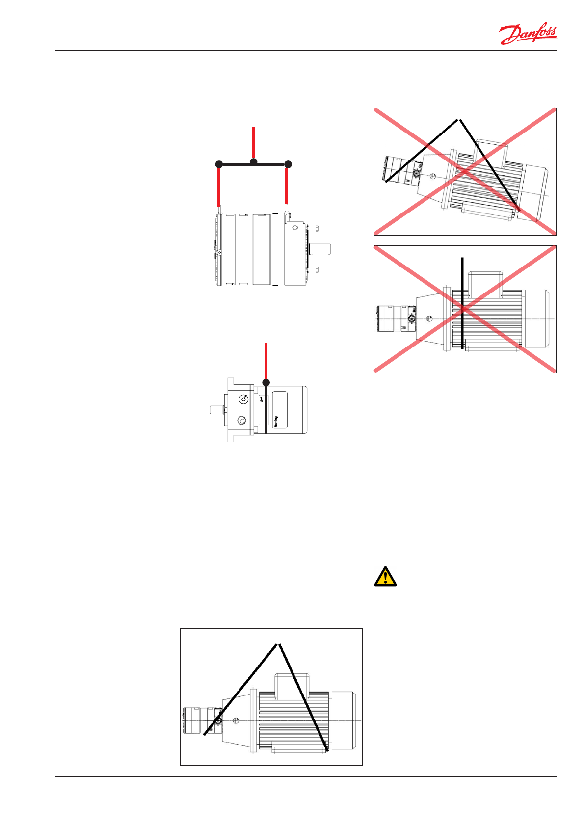
Correct lifting with 2 separate slings:
When lifting the pump unit, one sling must be
attached to the electric motor and one sling
around the pump.
Some motors and pumps have specific lifting
eyes.
Do not use connections/nozzles for lifting!
Do not use only one sling!
Make sure that the unit/load is balanced before
lifting. The centre of the mass varies from pump/
pump unit size to pump/pump unit.
How to mount the pump and the electric motor
correctly, see appendix 1, Data sheet or appendix
2, Instruction.
Incorrect lifting can result in personal injury
and/or damage to the pump unit, see appendix
2, Instruction.
4.5 Return to supplier
Please see maintenance chapter 7.
4.6 Storage
Each pump is tested before shipment, and will
therefore contain water. For storage temperature
and frost protection see appendix 2, Instruction.
The pumps are NOT delivered frost protected
from the factory.
180R9267 | AQ291128576527en-000901 IOM APP 1.5-3.5 Pumps | 12.2021
9
Page 10
Operating guide | APP 1.5-3.5 pumps
5. Installation and
commissioning
5.1 Important dimensions
Physical dimensions and connections of the
pump unit are described in appendix 1, Data
sheet.
5.2 Cleanliness
It is very important that the tubes and pipes are
completely clean: no dirt, chips or burrs are
allowed. Flush all piping before connecting the
high-pressure pump to ensure the system is
clean. Internal surfaces of the piping must not be
corroded. If dirt or rust is not removed, the pump
and the valves can be damaged. In worst case
the pump can be damaged beyond repair!
5.3 Fluid temperature
Before start-up, the fluid and pump housing
temperature must be within the specified
temperature range listed see appendix 1, Data
sheet.
5.4 Electrical data
Check voltage, current frequency and rated
power on the electric motor and VFD settings on
the name plate placed on both the motor and
the VFD.
5.5 Local regulations
Commissioning must always be done in
accordance with valid regulations and local
standards.
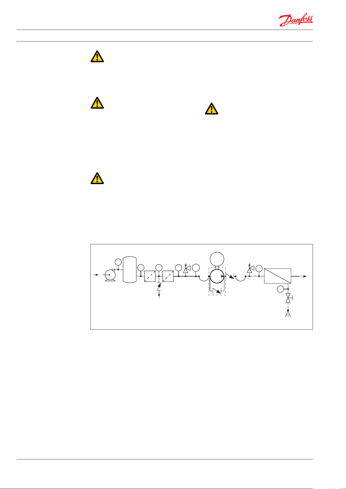
Schematic 1: Recommended system design
Media filter
Feed
PI
PI
PI PI
Fresh water
permeat flush
PT
M
PI
Brine
Permeate
PI
10
180R9267 | AQ291128576527en-000901 IOM APP 1.5-3.5 Pumps | 12.2021
Page 11
Operating guide | APP 1.5-3.5 pumps
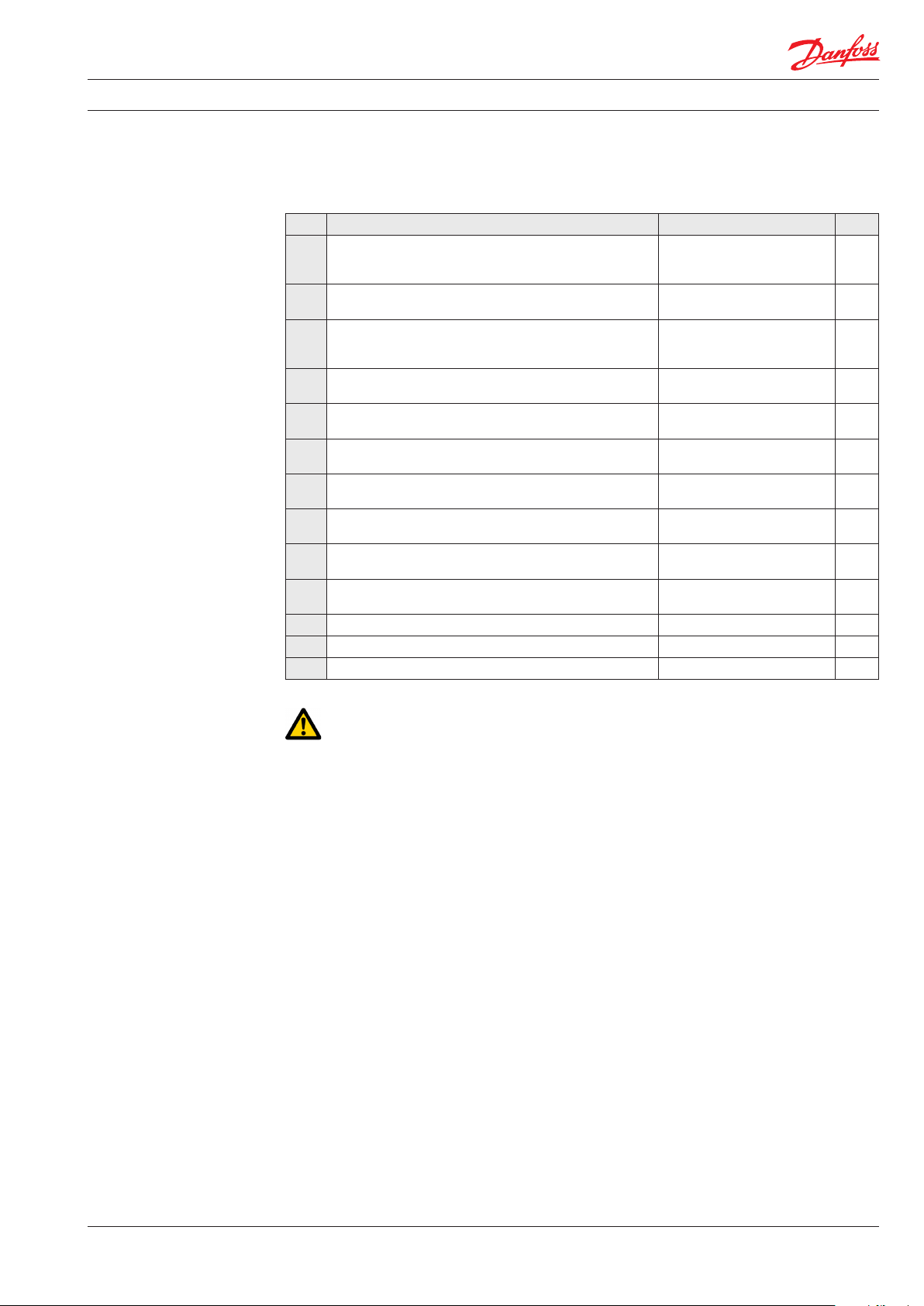
5.6 Pre mounting checklist, based on Danfoss preferred system design
Table 1: Check points when assembling and commissioning system
CP1
CP2
CP3
CP4
CP5
CP6
CP7
CP8
CP9
CP10
CP 11
CP12
CP13
Check points Comment OK ?
Ensure that the environmental conditions are safe. See Arrival inspection,
Minimum and maximum start-up temperature for fluid and
pump.
Filtration condition (10 µm absolute (ß10 ≥ 5000) See Danfoss requirements in
Power supply for electric motor and VFD. See Data sheet for the used
Safety circuit / breaker must be sized for the motor and
environment (corrosion and humidity)
Bolts and screws must conform to environmental conditions
as well as fluid and torque requirements.
Instrumentation, pressure switch should be designed to
conform to the environment (corrosion and humidity).
Check the factory settings of the safety/relief valves or
pressure relief valves (page 11).
Check the settings of the pressure transmitter/switch (3) set
at min. inlet pressure (page 11).
Check that all pressure indicators (PI) are selected to be able
to measure the system pressure range (page 11).
Check coupling distance ( air gab – movement of the spider ) 3-5 mm
Check correct connections on the pump ( in & outlet)
Check piping for possible air gaps.
transportation, handling,
lifting and storage, chapter 4.
See Data sheet or Instruction,
appendices 1 and 2.
Data sheet and Instruction,
appendices 1 and 2
motor and VFD.
See Data sheet for the used
safety circuit.
See Data sheet for the used
equipment.
See Data sheets for the used
valves.
See Data sheet or Instruction,
appendices 1 and 2.
Scaling should at least be 1 bar
or more precise.
5.7 Lifting and positioning
Lift the pump unit onto base (Remember
vibration dampeners, if needed). Fasten the
motor to the base.
See also chapter 4, Arrival inspection, transportation, handling, lifting and storage.
5.8 Mount the different equipment
(connections, pipes, tubes, check and safety/relief
valves, etc.)
• The hard piping and flexible hoses used,
must be of proper design and must be
installed in accordance with the manufacturer’s recommendations. (see also Data sheet
for Hose and hose fittings and Instruction for
Assembling Hose kit - both available on
www.ro-solutions.danfoss.com).
• Misalignment of the hard pipes may give
unintended stress on the pump port
connections and may damage the pump.
• Prevent excessive external pipe load.
• Do not connect piping by applying external
force (use of wrenches, crane, etc.) Piping
must be aligned without residual stress.
• Do not mount expansion joints so that their
force applies internal pressure on the pump
connections.
5.9 Electrics
All electrical installation work must be carried
out by authorized personnel in accordance with
EN60204-1 and/or local regulations (see also
Safety, chapter 2).
Turn off the safety circuit breaker and lock it.
Mount the power cable on the electric motor.
If a VFD is used, adjust the protective motor
switch/VFD to the current limits found on the
name plate of the electric motor.
5.10 Instrumentation
The pressure switch/sensor should be mounted
as close to the pump as possible. It is recommended to test the pressure/sensor switch via an
instrumentation manifold.
Mount the pressure switch/sensors according to
the manufacturer’s instructions.
5.11 Connections
Mount and tighten connections and check
valve(s) as specified.
180R9267 | AQ291128576527en-000901 IOM APP 1.5-3.5 Pumps | 12.2021
11
Page 12
Operating guide | APP 1.5-3.5 pumps
5.12 Ensure free flow
Ensure free flow from the safety/relief valves 8
and 9 (schematic 1, page 11). A blocked safety/
relief valve can cause excessive build-up of
pressure and thereby cause dangerous situations
and damage to the whole system.
5.13 Verify setting of safety/relief valves
Make sure, the safety/relief valves 8 and 9 are
placed correctly.
Check the pressure settings on the name plates
of the safety/relief valves. If they are within
specifications, you can continue.
5.14 Flush the pump
Fully open the pressure valve at the brine outlet.
Close all the bleeding and draining plugs on the
high-pressure pump.
Start the feed pump and ensure free flow to the
high-pressure pump.
5.15 Bleed and remove air from the pump
Open the bleeding plugs. Keep the plugs open
until the high-pressure pump is bleeded.
5.17 Commissioning
• Close all the bleeding and draining plugs.
• Open the pressure valve at the brine site.
• Switch the safety circuit breaker on for both
motor(s) and VFD(s).
• Start the feed pump.
• Start the high-pressure pump.
• If a VFD or a soft starter is used, a ramp up
time of minimum 10 seconds is required to
avoid damage of the pump.
• Monitor the inlet and outlet pressure of the
high-pressure pump and look for leakages.
• Check the function of the pressure
indicators by slowly closing the valves. The
pump unit should stop when the minimum
inlet pressure and maximum outlet
pressure has been reached.
• Adjust the pressures to the specified inlet
and outlet pressure for the system and let
the pump unit run until the electric motor
and pump temperature is stable.
• If the system is running within the system
design limits, the system is released for
operation.
5.18 Check the filter condition
Evaluate contamination found in filter, replace
filter elements, if necessary.
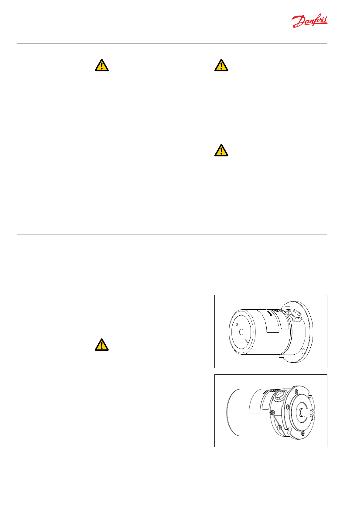
5.16 Verify direction of rotation
The direction of rotation must always follow the
arrow. The arrow is placed on the pump or pump
unit.
Check the direction of rotation before mounting
the pump.
Unlock the safety circuit breaker. Start the motor
for 1 second and observe the direction of
rotation either looking at the fan of the motor or
the coupling through the inspection hole in the
bell housings (not available on all bell housings).
If the motor is turning the wrong direction,
switch two phases in the connection box of the
motor or reprogram the direction in VFD.
When the motor is turning in the right direction,
the pump can be mounted.
5.19 Instruct operator and maintenance
personnel
Before using the pump/pump unit, the personnel
must be instructed in using the pump/pump
unit, its function, components, documentation
and safety.
Danfoss offers commissioning and service at
system manufacturer’s location. Rate quotes are
offered upon request.
12
180R9267 | AQ291128576527en-000901 IOM APP 1.5-3.5 Pumps | 12.2021
Page 13
Operating guide | APP 1.5-3.5 pumps
6. Operation of pump
unit
6.1 General safety information
Before inspecting the pump unit, read the Safety
chapter 2 in this user manual.
6.2 What to listen and look for
If one or more of the following examples are
observed, please act as indicated:
A) Loose bolts – check all bolts and, if
necessary, contact the maintenance
department in order to have all bolts
tightened to the specified torque(s).
B) Leakage – if a small leakage from the bell
housing is observed. Contact the maintenance department.
C) Leakage – if there is a large leak, the unit
should be stopped immediately. Contact
the maintenance department.
D) High frequency tones – safety/relief valves
are either damaged or running very close
to their design pressure, stop the unit
immediately. Contact the maintenance
department.
E) Increased noise or vibration – requires the
unit to be stopped immediately. Contact
the maintenance department.
F) Very high temperatures – may indicate that
one or more parts are damaged inside the
pump. The pump must be stopped
immediately and inspected before it is
restarted. Contact the maintenance
department.
G) Drop in flow and/or pressure – may indicate
wear on one or more parts inside the
pump. The pump must be stopped
immediately and inspected before it is
restarted. Contact the maintenance
department.
H) Other observations or troubles, please see
appendix 7, Right and Wrong or appendix
6, the Trouble shooting guide.
Both appendices give good advises
regarding design, installation, wiring and
troubleshooting.
See also service and warranty section in
appendix 1, Data sheet and appendix 2,
Instruction.
If the pump is not stopped for inspection as
recommended, it can lead to damage of the
pump or break-down. See also service and
warranty section in the appendix 1, Data sheet,
in appendix 2, Instruction or appendix 4,
Instruction for recommended service intervals.
Danfoss offers service of the pump at the system
manufacturer’s location as well as we offer
training in how to service the pump. Quotes are
offered upon request.
Danfoss recommends simultaneously to check
the filter and membrane condition and to
evaluate contamination; filter and membrane
elements must be replaced if necessary.
7. Maintenance and
service of the pump
unit 7.1 General safety information
Before servicing the pump unit, it is necessary to
read and understand this user manual, especially
the Safety, chapter 2. Remember to wear suitable
safety equipment according to Safety, chapter 2.
7.2 Service and inspection interval for the
pump
Maintenance and service intervals are depending
on the cleanliness level of the water, hydraulic
load and temperature of the pump unit. The
most important parameter is the filtration of the
water.
See the section Service and warranty in the
appendix 1, Data sheet, in appendix 2, Instruction and appendix 4, Instruction for recommended service intervals.
For spare parts and service tools, please see
appendix 3, Parts list.
180R9267 | AQ291128576527en-000901 IOM APP 1.5-3.5 Pumps | 12.2021
Danfoss offers service of the pump at the system
manufacturer’s location and training in how to
service the pump. Quotes are offered upon
request.
7.3 Shut down of the system
A) Open the pressure valves at the brine site
to release the pressure.
B) Stop the high-pressure pump.
C) Stop the feed pump.
D) Switch off the safety circuit breaker for
both the high-pressure pump, feed pump
and VFD and lock them. Only personnel
servicing the pump unit should be able to
unlock/activate the switch again.
E) Open bleeding and drain plugs. Wait until
the pump and system are emptied for
water.
13
Page 14
Operating guide | APP 1.5-3.5 pumps
F) Slowly unscrew and remove the bolts and
gaskets from the inlet/outlet hoses or
pipes, be careful about jets of water.
Beware that the system can be pressurized!
G) Attach the lifting equipment to the pump
unit. For instructions on lifting the
complete pump unit, see chapter 4, Arrival
inspection, transportation, handling, lifting
and storage.
H) For the small pumps, unscrew the bolts
holding the pump to the bell housing. For
the bigger pumps, unscrew the bolts/nuts
from the pump and bell housing to the
motor. Afterwards unscrew the bolts/nuts
holding the pump and bell housing.
I) Carefully pull the pump out of the bell
housing by using lifting equipment, if
necessary.
J) Hold the pump in different positions above
a drip tray; this should allow most of the
water trapped in the pump to drain. Clean
and dry the pump surface and plug the
bleeding and draining plugs.
K) Move the pump to a clean and safe location
where the pump can be inspected/
serviced.
7.4 Disassembling and assembling the
pump unit
A) Remove all connections from the pump.
B) Disassemble the pump according to the
Disassembling and Assembling Instruction
(available at www.ro-solutions.danfoss.com)
Clean all parts and surfaces with a fluid
compatible with the materials found in the
pump. Wipe the parts clean and dry with a
lint-free clothing.
Returns without a return number will be
rejected !!!
7.5 Assembling the pump unit
Assemble the pump according to the Disassembling and Assembling Instruction
(available at www.ro-solutions.danfoss.com).
7.6 Procedure for mounting the pump onto
the electric motor
Mount the flexible coupling and bell housing
according to appendix 2, Instruction.
7.7 Getting the pump unit back into
operation
Find instructions of how to put the pump unit
back into operation in chapter 4, Arrival inspection, transportation, handling, lifting and storage
and Installation and commissioning, chapter 5.
7.8 Storage of the pump
If the pump has to be shut down for a longer
period, instructions can be found in appendix 2,
Instruction.
C) Inspect all parts including shaft seal and if
necessary, replace them; see appendix 3,
Parts list.
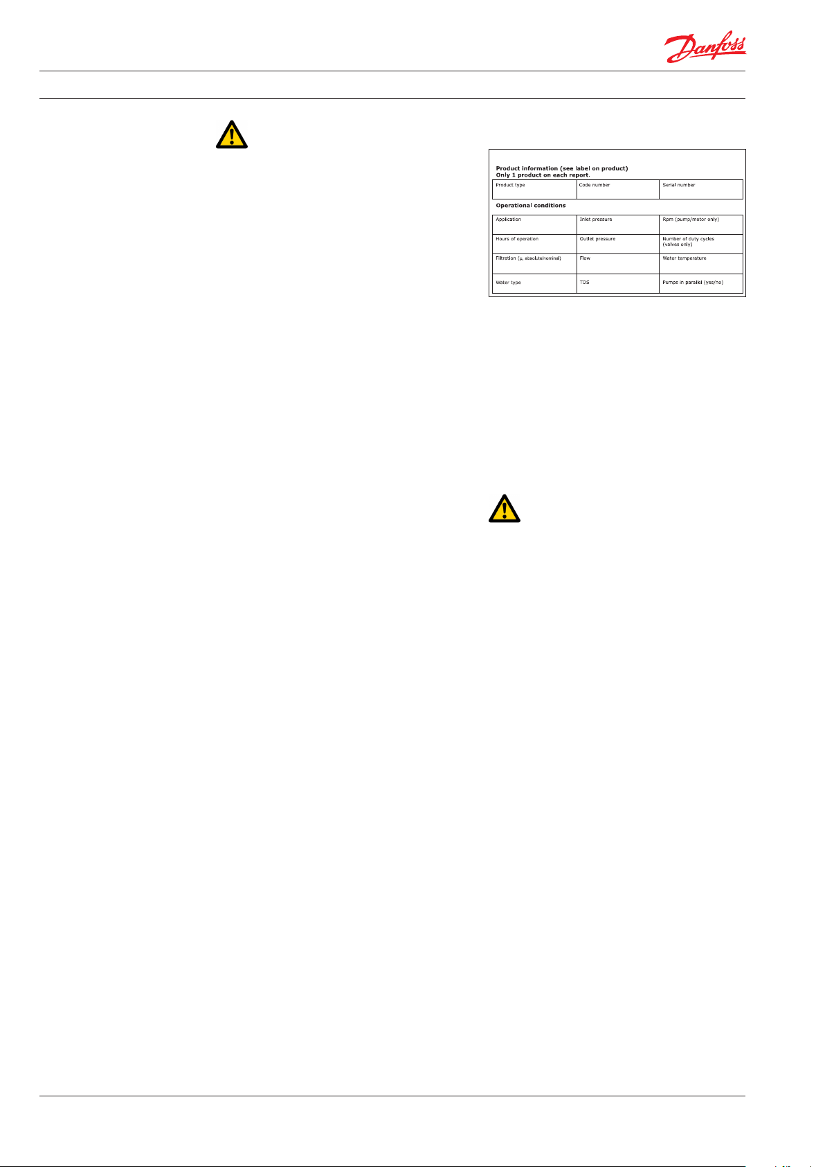
D) If the pump is going to be returned to
Danfoss for repair or a warranty claim, it is
important to contact Danfoss in order to
receive a return number and a form to fill
out with product information. A copy of the
form together with contact information
and reason for returning should be sent to
the email address on the form. The same
documents should be attached to the
shipment.
14
180R9267 | AQ291128576527en-000901 IOM APP 1.5-3.5 Pumps | 12.2021
Page 15
Operating guide | APP 1.5-3.5 pumps
8. Troubleshooting and
scrapping criteria
8.1 General safety information
Before inspecting the pump unit, it is necessary
to read and understand this user manual,
especially the Safety chapter 2.
Remember to wear suitable safety equipment
according to Safety chapter 2.
8.2 Operational conditions which can cause
pump failures
The following conditions can cause a pump
failure :
If water is leaking into the electric motor; it can
cause electric shock, fire, short circuit or even
death. When mounting the pump vertically
always mount the motor above the pump to
avoid water leaking into the electric motor.
8.4 Electrical failure
If the wiring of the electric motor is incorrect or
the ground connection is missing, it can cause
electric shock, burn damages, fire or even death.
• The pump is running dry.
• The inlet pressure is too high.
• The inlet pressure is too low.
• The temperature of the fluid is too high.
• The ambient temperature is too high.
• The pump is running against a blocked
port/closed manual valve.
• The pump is operating at a pressure out of
specification.
• The pump is running with a non-specified/
approved fluid.
• The pump is running in the wrong
direction.
• The filtration is insufficient.
• The pump is not being serviced according
to Danfoss specifications (end of life).
• There is excessive mechanical load on the
shaft coupling and piping.
8.3 Mechanical failure
If the pump is running dry, the temperature will
quickly increase which can cause burns.
If there is any leakage at start-up or during
operation, a high-pressure jet can cause eye or
skin damage.
Leakage can result in flooding, which can cause
slipping, tripping or falling.
If a VFD is used and wrongly programmed, it can
damage the pump and lead to high temperatures or other dangers.
All electrical installation must be carried out by
authorized personnel in accordance with
EN60204-1 and/or local regulations.
8.5 Responsibility
Danfoss takes no responsibility for any abnormal
injuries, risks or damages that could arise caused
by abnormal conditions, vibrations, corrosion,
abrasives, foreign objects or excessive temperatures and shall not be liable for any consequential or incidental damages.
8.6 Scrapping criteria
Whether the pump can be repaired or need to be
scrapped, depends on in which conditions the
internal parts are, or how damaged the whole
unit is. Please use appendix 6, Trouble shooting
guide as guideline or send the pump to Danfoss
headquarter in Denmark for evaluation.
For other observations or troubles, please see
appendix 7, Right and Wrong which gives good
advises regarding design, installation, wiring and
troubleshooting.
In case the pump needs to be scrapped, please
follow your local environmental rules.
180R9267 | AQ291128576527en-000901 IOM APP 1.5-3.5 Pumps | 12.2021
15
Page 16

User manual Installation, Operation and Maintenance APP Pumps (APP 1.5-3.5)
Danfoss A/S
High Pressure Pumps
DK-6430 Nordborg
Denmark
Danfoss ca n accept no respons ibility for pos sible errors in ca talogues, bro chures and other pr inted material. Da nfoss reserve s the right to alter its p roducts with out notice.
This also a pplies to produc ts already on ord er provided that su ch alterations ca n be made without su bsequential cha nges being nece ssary in speci fications alread y agreed.
All trade marks in this mate rial are proper ty of the respec tive companies . Danfoss and the Danf oss logotyp e are trademark s of Danfoss A/S. Al l rights reserv ed.
16
180R9267 | AQ291128576527en-000901 IOM APP 1.5-3.5 Pumps | 12.2021
Page 17
Operating guide
Appendices
APP 1.5 - 3.5
Installation, Operation and
Maintenance Manual
hpp.danfoss.com
Page 18

Operating guide | APP 1.5-3.5 pumps
Table of Contents
Contents
Appendices ......................................................................................17
1. Data sheet for APP 1.5-3.5 (AI274333290009en-000701) .................................19
2. Pump instruction APP 1.5-3.5 (180R9065) ...............................................33
3. IOM Electric motors (180R9230)..........................................................41
4. Recommended service intervals for APP pumps (AX290239527130en-000201)...........47
5. Parts list for APP 1.5-3.5 (AX274346749037en-000501)...................................51
6. Trouble shooting guide for APP, APP S and APP S 674 pumps ............................61
7. Right and wrong (180R9042) ...........................................................73
18
180R9267 | AQ291128576527en-000901 IOM APP 1.5-3.5 Pumps | 12.2021
Page 19
Data sheet
Data sheet
APP Pumps
APP 0.6-1.0 / APP 1.5-3.5 /
APP pumps
APP (W) 5.1-10.2 / APP 11-13 /
APP 0.6-1.0 / APP 1.5-3.5 / APP (W) 5.1-10.2 /
APP 16-22 / APP 21-46
APP 11-13 / APP 16-22 / APP 21-43
hpp.danfoss.com.
ro-solutions.com
Page 20

Data sheet | APP 0.6-46 / APP (W) 5.1-10.2 pumps
Table of Contents
1. Introduction ...........................................................................21
2. Benefits................................................................................21
3. Application examples ..................................................................21
4 Technical data .........................................................................22
4.2 APP 1.5-3.5.............................................................................22
5. Flow at different rpm...................................................................23
5.2 APP 1.5-3.5 flow curves at 80 barg (1160 psig) ...........................................23
6 Flushing valve curves ..................................................................24
6.2 APP 1.5–3.5 integrated flushing valve ...................................................24
7. Motor requirements....................................................................25
7.2 Calculation factor for APP 1.5-3.5 .......................................................25
8. Temperature and corrosion.............................................................26
8.1 Temperature...........................................................................26
9. Installation.............................................................................26
9.1 Filtration...............................................................................27
9.2 RO system with direct supply: ..........................................................27
10. Dimensions and connections...........................................................29
10.2 APP 1.5-3.5.............................................................................29
11. Dimensions with motor unit ............................................................30
11.1 APP 0.6-3.5.............................................................................30
13. Ser vice.................................................................................31
20
180R9267 | AQ291128576527en-000901 IOM APP 1.5-3.5 Pumps | 12.2021
Page 21
Data sheet | APP 0.6-46 / APP (W) 5.1-10.2 pumps
1. Introduction
This data sheet is valid for APP pumps both non
ATEX and ATEX certified. ATEX certified pumps
are indicated by Ex in the type designation example APP 0.6 Ex.
The Danfoss range of APP high-pressure pumps
is designed according to EN 809 for use in RO
applications with low viscosity and corrosive
fluids such as:
• Sea water
• Brackish water
• Waste water (APP W)
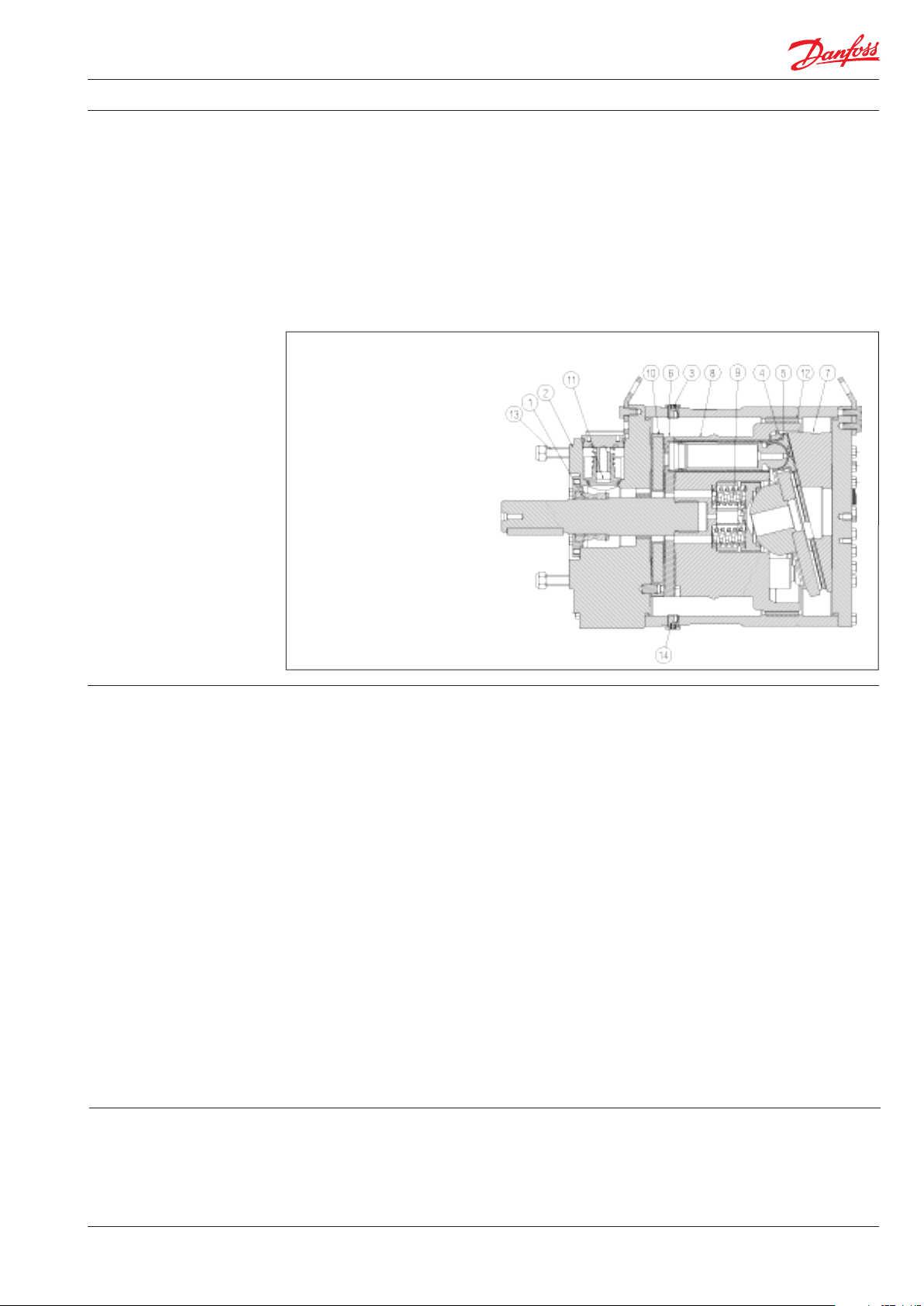
1: Shaft sealing
2: Port flange
3: Bleeding plug
4: Retainer plate
5: Piston/shoe
6: Valve plate
7: Swash plate
8: Cylinder barrel
9: Springs
10: Port plate
11: Flushing valve
(not available on
APP 5.1-10.2)
12: Housing
13: Tail stock screws
14: Drain plug
Danfoss APP pumps are positive displacement
pumps with axial pistons that move a fixed
amount of water in each cycle. Flow is proportional to the number of input shaft revolutions
(rpm). Unlike centrifugal pumps, they produce
the same flow at a given speed no matter what
the discharge pressure.
Below sectional drawing is an example of an
APP pump. The sectional drawing for the specific
pump sizes are to be found in the pump
instruction.
2. Benefits
• Zero risk of lubricant contamination:
- Oil lubricants are replaced with the
pumped medium, water, so there is no
contamination risk from the pump.
• Low maintenance costs:
- Efficient design and all-stainless steel
construction ensure exceptionally long
life. When Danfoss specifications are
met, service intervals of 8,000 hours can
be expected. Service is easy, and can be
carried out on-site due to the simple
design and few parts.
• Low energy costs:
- The highly efficient axial piston design
provides the lowest energy
consumption of any comparable pump
on the market.
• Easy installation:
- The most compact and lightest design
available.
- The pump can be installed vertically
and horizontally.
- No pulsation dampeners necessary due
to extremely low pressure pulsation.
3. Application examples Danfoss APP pumps are built into a broad range
of RO desalination plants around the world:
• Containerized solutions for hotels, resorts
and residences on islands and in coastal
regions
- Powered directly by electric motors or
combustion engines (with special
coupling).
- All pumps except APP (W) 5.1 - 10.2 are
supplied with an integrated flushing
valve that allows the fluid to flow
from inlet to the outlet, when the pump
is not running.
• High reliability:
- All parts are made of high corrosion
resistant materials e.g. Duplex
(EN1.4462/ UNS S31803) and
Super Duplex (EN1.4410/UNS S32750)
stainless steel and carbon reinforced
PEEK.
• Certified quality:
- Pumps available as ATEX certified.
- For other certifications, please see data
sheets for APP S (all super duplex) and
APP S 674 (API).
- Positive Material Identification (PMI)
report available on request.
- IATF 16949, ISO 9001, ISO 14001.
• Mobile systems for humanitarian and
military organizations
• Onboard systems for ships and yachts
• Offshore platforms for the oil and gas
industry
• Municipal and regional waterworks
180R9267 | AQ291128576527en-000901 IOM APP 1.5-3.5 Pumps | 12.2021
21
Page 22
Data sheet | APP 0.6-46 / APP (W) 5.1-10.2 pumps
4 Technical data
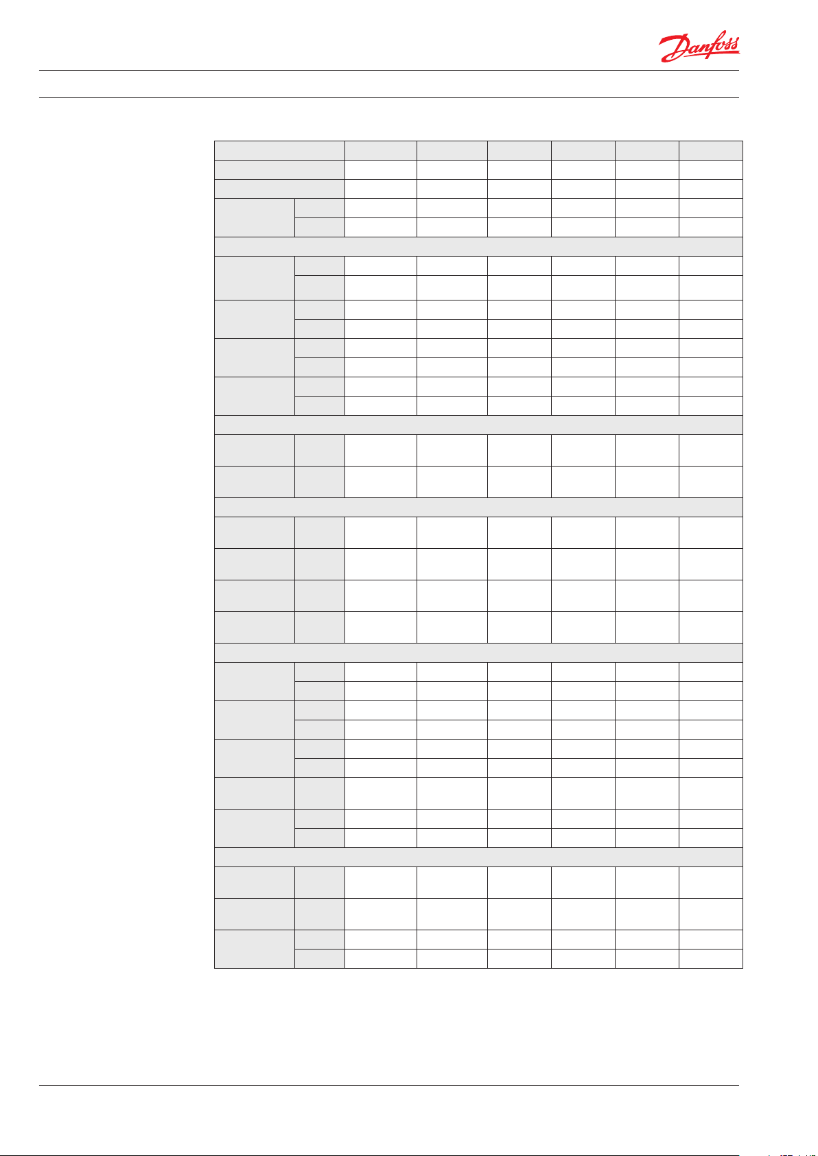
4.2 APP 1.5-3.5
Pump size APP 1.5 APP 1.8 APP 2.2 APP 2.5 APP 3.0 APP 3.5
Code number APP 180B30 43 180B3044 180B3045 180B30 46 180B3030 180B3032
Code number APP ATEX4)180 B3143 180B3144 180B3145 180B3146 18 0B3130 18 0B3132
Geometric
displacement
cm³/rev.
in³/rev.
Pressure
Max. outlet
pressure
continuous
Min. outlet
pressure
Inlet pressure
continuous
Max. inlet
pressure peak
1)
barg 83 83 83 83 83 83
psig 120 0 1200 12 00 12 00 120 0 120 0
1)
barg 20 20 20 20 20 20
psig 290 290 290 290 290 290
barg 0.5 - 5
psig 7.3 - 72.5
barg 10 10 10 10 10 10
psig 145 145 145 145 145 145
Speed
Min. speed
continuous
Max. speed
continuous
rpm 700 700 700 700 700 700
rpm 3450
Typical flow - Flow curves available in item 5
1000 rpm at
max. pressure
1500 rpm at
max. pressure
1200 rpm at
max. pressure
1800 rpm at
max. pressure
m³/h 0.53 0.57 0.73 0.90 1.02 1.19
m³/h 0.79 0.86 1.09 1.34 1.54 1.79
gpm 2.80 3.03 3.83 4.73 5.41 6.30
gpm 4.19 4.55 5.75 7. 09 8.12 9.46
Technical specifications
Media 3)
temperature
Ambient
temperature
Weight (dry)
Sound
pressure level
Footprint with
IEC motor
°C 2 - 50 2 - 50 2 - 50 2 - 50 2 - 50 2 - 50
°F 36 - 122 36 - 122 36 - 122 36 - 122 36 - 122 36 - 122
°C 0 - 50 0 - 50 0 - 50 0 - 50 0 - 50 0 - 50
°F 32 - 122 32 - 122 32 - 122 32 - 122 32 - 122 32 - 122
kg 8.6 8.6 8.6 8.6 8.6 8.6
lb 17 17 17 17 17 17
dB(A) 77 77 77 81 81 81
5)
m² 0.15 0.16 0.21 0. 21 0.30 0.30
6)
foot² 1.61 1.72 2.26 2.26 3.23 3.23
Typical motor size
Max. speed at
max. pressure
3000 rpm at
max. pressure
Torque at max.
outlet pressure
kW 5.5 5.5 7.5 7. 5 11 11
HP 7.5 7.5 10.0 15 .0 15. 0 15.0
Nm 13.0 13.9 17. 4 21.3 24.5 28.7
lbf-ft 9.6 10.3 12 .8 15.7 18.1 21.2
9.31 10.0 4 12.52 15.35 17.70 20.54
0.57 0.61 0.76 0.94 1.08 1.25
2)
2)
7.3 - 72.5 2)7.3 - 72.5
2)
0.5 - 5
3450
2)
2)
0.5 - 5
3450
2)
2)
2)
0.5 - 5 0.5 - 5
7.3 - 72.5 7.3 - 72.5
3000 3450
2)
2)
2)
7.3 - 72.5
0.5 - 5
3000
22
1)
For lower an d higher pressure , please contact D anfoss.
2)
For spee ds above 3000 rpm t he pump must be boo sted at a pressure
of 2-5 barg (29 - 72.5 psig).
3)
Depend ent on the NaCI conce ntration - see chap ter 8.
4)
Category 2, Zone 1 or Category 3, Zone 2.
180R9267 | AQ291128576527en-000901 IOM APP 1.5-3.5 Pumps | 12.2021
5)
A-weigh ted sound pressur e level at 1 m from the pum p unit
surfa ces (reference box) a cc. to EN ISO 20361 section 6 .2. The noise
measurem ents are perf ormed acc. to EN ISO 3744:2010 on a mot or-
pump unit a t max. pressure an d speed.
6)
Max. area covered with recommended motor configuration
(excl. of spa ce to service pump)
Page 23
Data sheet | APP 0.6-46 / APP (W) 5.1-10.2 pumps
APP 1.5
APP 1.8
APP 2.2
APP 2.5
APP 3.0
APP 3.5
rpm
4.5
4.0
3.5
3.0
2.5
2.0
1.5
1.0
0
0.5
1300
1500
1100
1900
2100
1700
2500
2700
2300
3100
3300
3450
2900
900
700
m3/h
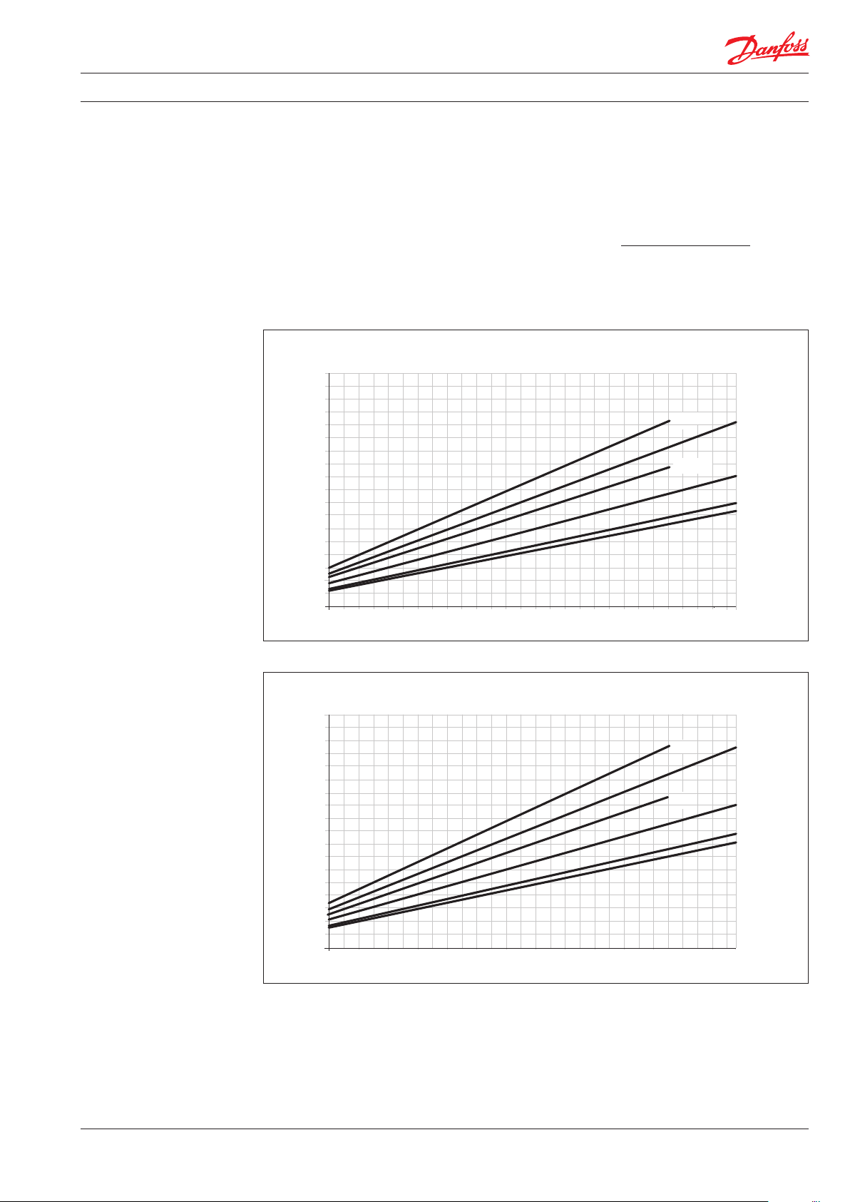
5. Flow at different rpm
If the flow required and the rotation speed (rpm) of the
pump is known, it is easy to select the pump fitting the
application best by using the diagrams below.
5.2 APP 1.5-3.5 flow curves at 80 barg (1160 psig)
m3/h
4.5
4.0
3.5
3.0
2.5
2.0
1.5
Furthermore, these diagrams shows that the
flow can be changed by changing the rotation
speed of the pump. The flow/rpm ratio is
constant, and the “required” flow can be
obtained by changing the rotation speed to a
corresponding value. Thus, the required rpm
can be determined as:
Required flow x Rated rpm
Required rpm =
Rated flow
APP 3.5
APP 2.5
APP 3.0
APP 2.2
APP 1.8
APP 1.5
1.0
0.5
3450
3450
rpm
APP 3.0
APP 2.2
APP 1.8
APP 1.5
rpm
0
700
900
1100
1300
gpm
1100
1300
18.0
16.0
14.0
12.0
10.0
8.0
6.0
4.0
2.0
0
700
900
1500
1500
1700
1700
1900
1900
2100
2100
2300
2300
2500
2500
2700
2700
2900
2900
3100
APP 3.5
APP 2.5
3100
3300
3300
180R9267 | AQ291128576527en-000901 IOM APP 1.5-3.5 Pumps | 12.2021
23
Page 24
Data sheet | APP 0.6-46 / APP (W) 5.1-10.2 pumps
Pressure [barg]
ow [l/min]
0.5
1.0
1.5
2.0
2.5
3.0
3.5
4.0
4.5
5.0
10
12
14
16
18
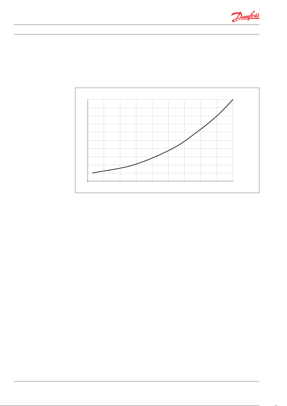
6 Flushing valve curves
All pumps except APP (W) 5.1 - 10.2 are supplied
with an integrated flushing valve that allows the
fluid to flow from inlet to the outlet, when the
pump is not running.
6.2 APP 1.5–3.5 integrated flushing valve
0
0
2
4
6
8
Fl
24
180R9267 | AQ291128576527en-000901 IOM APP 1.5-3.5 Pumps | 12.2021
Page 25

Data sheet | APP 0.6-46 / APP (W) 5.1-10.2 pumps
The power requirements can be determined using one of the following guiding equations:7. Motor requirements
l/min x barg 16.7 x m3/h x barg 0.´35 x gpm x psig
Required power = [kW] or [kW] or
Calc. factor Calc. factor Calc. factor
1 hp = 0.75 kW
1 gpm = 3.79 l/min
1 m3/h = 4.40 gpm
1 kW = 1.34 hp
1 l/min = 0.26 gpm
1 gpm = 0.23 m3/h
7.2 Calculation factor for APP 1.5-3.5
Name rpm Calculation
factor
APP 1.5 3450 519
APP 1.8 3450 524
APP 2.2 3450 532
APP 2.5 3000 535
APP 3.0 3450 532
APP 3.5 3000 530
[hp]
180R9267 | AQ291128576527en-000901 IOM APP 1.5-3.5 Pumps | 12.2021
25
Page 26

Data sheet | APP 0.6-46 / APP (W) 5.1-10.2 pumps
8. Temperature and
corrosion
8.1 Temperature
Fluid temperature:
Min. +2°C to max. +50°C
(Min. +35.6°F to max. +122°F)
Ambient temperature:
Min. +2°C to max. +50°C
(Min. +35.6°F to max. +122°F)
In case of lower operating temperatures, please
contact Danfoss High Pressure Pumps.operation
º
80
C
Duplex
70
60
50
316L
40
30
20
100
160 1600
1000
10 000
16000
stop in order to minimize the risk of crevice
corrosion.
The chart below illustrates the corrosive
resistance of different types of stainless steel
related to NaCl concentration and temperature.
The APP water pump is made of Duplex and
Super Duplex.
If the water pump is operated above the Duplex
line, always flush water pump with fresh water at
operation stop in order to minimize the risk of
crevice corrosion.
NaCI vs. temperature
Super Duplex
-
100 000
160000
CI
ppm
NaCI
ppm
9. Installation See example below on how to mount the pump
and connect it to an electric motor or combustion engine (special coupling).
A: Pump
B: Bell housing
C: Flexible coupling
D: Motor shaft
E: Motor
A
B
If alternative mounting is required. please
contact your Danfoss sales representative for
further information.
Note: Do not add any axial or radial loads to the
pump shaft.
EC D
26
180R9267 | AQ291128576527en-000901 IOM APP 1.5-3.5 Pumps | 12.2021
Page 27

Data sheet | APP 0.6-46 / APP (W) 5.1-10.2 pumps
9.1 Filtration
Proper filtration is crucial for the performance.
maintenance and warranty of your pump.
Protect your pump, and the application in which
it is installed, and by always ensuring that all
filtration specifications are met, and by always
changing filter cartridges according to schedule.
Since water has very low vicosity, Danfoss APP
pumps have been designed with very narrow
clearances in order to control internal leakage
rates and improve component performance.
To minimize wear on the pump, it is therefore
essential to filter inlet water properly.
The main filter must have a filtration efficiency
of 99.98% at 10 μm. We strongly recommend
that you always use precision depth filter
cartridges rated 10μm abs. ß10≥5000.
Please note that we do not recommend bag
filters or string-wound filter cartridges, which
typically have only 50% filtration efficiency. This
means that out of the 100,000 particles that
enter such filters, 50,000 particles pass right
through; compare this to precision depth filters
that are 99.98% efficient, and only allow 20 of the
same 100,000 particles to pass through.
For more information on the importance of
proper filtration, including explanation of
filtration principles, definitions and guidance on
how to select the right filter for your pump,
please consult our Filtration information and
specifications (Danfoss document number
521B1009).
Noise
Since the pump unit is typical mounted on a
frame or bell housing the overall noise level can
only be determined for a complete system. To
minimize vibrations and noise throughout the
system, it is therefore very important to mount
the pump unit correctly on a frame with
anti-vibration-dampeners, and to use flexible
hoses rather than metal pipes where possible.
The noise level is influenced by:
• Pump speed:
High rpm generates more fluid/structure
borne pulsations/vibrations than low rpm,
because of higher frequency.
• Discharge pressure:
High pressure generates more noise than
low pressure.
• Pump mounting:
Rigid mounting generates more noise than
flexible mounting, because of structureborne vibrations. Be sure to use dampers
when mounting.
• Connections to pump:
Pipes connected directly to the pump make
more noise than flexible hoses, because of
structure-borne vibrations.
• Variable frequency drives (VFD):
Motors regulated by VFDs can produce
more noise if the VFD does not have the
right settings.
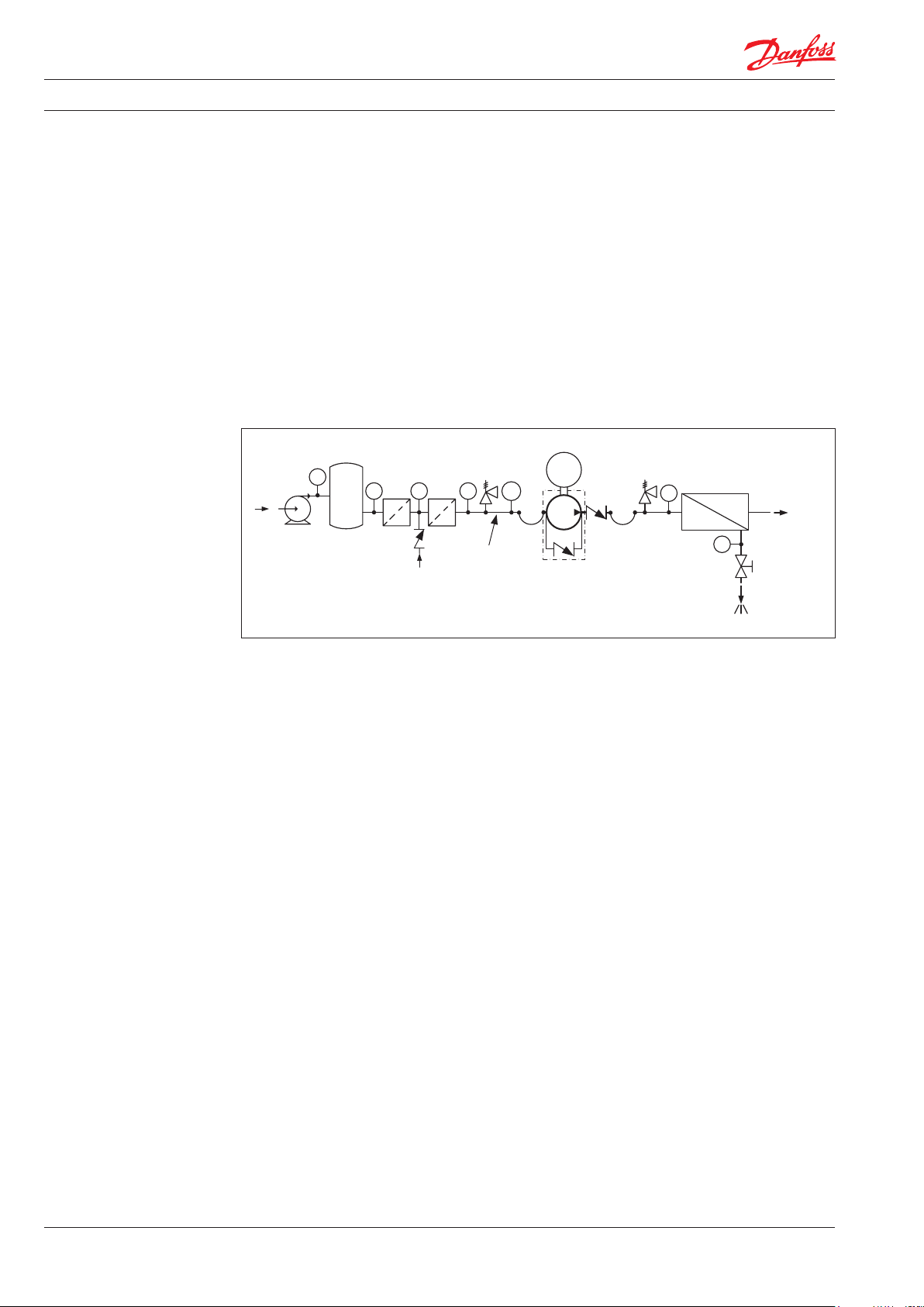
9.2 RO system with direct supply:
Inlet line:
a) Dimension the inlet line to obtain
minimum pressure loss (large flow,
minimum pipe length, minimum number
of b ends/connections, and fit tings with low
or no pressure losses). If relevant, please
consult “Parallel coupled pumps and
iSaves” (180R93549)
Inlet filter:
b) Install an inlet filter (1) in front of the APP
pump (2). Please consult section 9.1,
“Filtration” for guidance on how to select
the right filter. Thoroughly clean pipes and
flush system prior to start-up.
Low pressure relief valve:
c) Install a low pressure relief valve (9) in order
to avoid system or pump damage in case
the pump stops momentarily or is spinning
backwards.
Monitoring pressure switch:
d) Install a monitoring pressure switch (3)
between the filter (1) and the pump inlet.
Set the minimum inlet pressure according
to specifications described in item 4 about
technical data. If the inlet pressure is lower
than the minimum pressure set, the
monitoring pressure switch must prevent
the pump from starting or from running.
Hoses:
e) Use flexible hoses (4) to minimize
vibrations and noise. Please consult the
Danfoss Hoses and hose fittings data
sheet (521B0909) for guidance.
Inlet pressure:
f) In order to eliminate the risk of cavitation
and other pump damage, pump inlet
pressure must always be maintained
according to specifications described in
item 4 about technical data.
Flushing valve:
g) For easy system filling and flushing, an
integrated flushing valve (6) is in
the APP pump (except APP (W) 5.1-10.2).
Non-return valve:
h) A non-return valve (7) in outlet can be
installed in order to avoid backspin of the
pump. The volume of water in the
membrane vessel works as an accumulator
and will send flow backwards in case of the
pump stops momentarily.
180R9267 | AQ291128576527en-000901 IOM APP 1.5-3.5 Pumps | 12.2021
27
Page 28
Data sheet | APP 0.6-46 / APP (W) 5.1-10.2 pumps
High pressure safety or relief valve:
i) As the Danfoss APP pump begins to create
pressure and flow immediately after
start-up and regardless of any counter
pressure, a safey or pressure relief valve (8)
should be installed after the non-return
valve to prevent system damage and to
avoid high pressure peaks.
Note: If a non-return valve is mounted in the inlet
line, a low-pressure relief valve is also required
between the non-return valve and
pump as protection against high-pressure peaks.
Preferred design - see section 9.2
Feed
Media filter
PI
1
PI
1
PI PI
Fresh water
permeat flush
9 3
5
M
PT
2
7
4
6
PI
Brine
Permeate
PI
28
180R9267 | AQ291128576527en-000901 IOM APP 1.5-3.5 Pumps | 12.2021
Page 29

Data sheet | APP 0.6-46 / APP (W) 5.1-10.2 pumps
10. Dimensions and
connections
10.2 APP 1.5-3.5
180R9267 | AQ291128576527en-000901 IOM APP 1.5-3.5 Pumps | 12.2021
29
Page 30

Data sheet | APP 0.6-46 / APP (W) 5.1-10.2 pumps
11. Dimensions with motor
unit
11.1 APP 0.6-3.5
The examples of assemblies with motor are only
for IEC motors and couplings. Please make sure
to check required motor power and dimensions
when selecting size of pump and motor. For advice and calculation tool, please contact Danfoss.
Pump
APP 0.6
APP 0.8
APP 1.0
APP 1.5
APP 1.8
APP 2.2
APP 2.5
APP 3.0
APP 3.5
A mm
(inch)
200
(7.8 7)
200
(7.8 7)
250
(9.84)
250
(9.84)
250
(9.84)
300
(11.81)
300
(11.81)
350
(13. 78)
350
(13. 78)
B mm
(inch)
(9.64)90(3.54)
(9.64)90(3.54)
(10.23)
(10.23)
(11.4 2)
(13.31)
(13.31)
(17. 40 )
(17. 40
245
245
260
260
290
338
338
422
422
C mm
(inch)
100
(3.94)
100
(3.94)
112
(4.41)
132
(5.20)
132
(5.20)
160
(6.30)
160
(6.30)
D mm
(inch)
140
(5.51)
140
(5.51)
160
(6.30)
160
(6.30)
190
(7.4 8)
216
(8.50)
216
(8.50)
254
(10.0)
254
(10.0)
E mm
(inch)
100
(3.94)
125
(4.92)
140
(5.51)
140
(5.51)
140
(5.51)
140
(5.51)
178
(7.01)
210
(8.27)
210
(8.27)
F mm
(inch)
265
(10.43)
290
(11.4 2)
325
(12.8 0)
325
(12.8 0)
340
(13. 39)
403
(15. 87)
403
(15. 87)
505
(19.88)
505
(19.88)
G mm
(inch)
100
(3.94)
100
(3.94)
120
(4.72)
120
(4.72)
120
(4.72)
144
(5.67)
144
(5.67)
188
(7.4 0)
188
(7.4 0)
H mm
(inch)
131
(5.16)
131
(5.16)
131
(5.16)
166
(6.54)
166
(6.54)
166
(6.54)
166
(6.54)
166
(6.54)
166
(6.54)
IEC Electric motor
1.5 kW, IEC 90S-2
2.2 kW, IEC 90L-2
3.0 kW, IEC 100L-2
3.0 kW, IEC 100L-2
4.0 kW, IEC 112M-2
5.5 kW, IEC 132S1-2
7.5 kW, IEC 132S2-2
11 kW, IEC 160M1-2
11 kW, IEC 160M1-2
30
180R9267 | AQ291128576527en-000901 IOM APP 1.5-3.5 Pumps | 12.2021
Page 31

Data sheet | APP 0.6-46 / APP (W) 5.1-10.2 pumps
13. Service
Warranty
Danfoss APP pumps are designed for long
operation, low maintenance and reduced
lifecycle costs.
Provided that the pump has been running
according to the Danfoss specifications, Danfoss
guarantees 8,000 hours service-free operation,
however, max. 18 months from date of
production.
If Danfoss recommendations concerning
system-design are not followed, it will strongly
influence the life of the APP pumps.
Other factors that affect pump performance and
lifetime include:
- Running the pump at speed outside
specifications.
- Supplying the pump with water at
temperature higher than recommended.
- Running the pump at inlet pressure outside
specifications.
- Running the pump at outlet pressure
outside the specifications.
Pump shutdown:
The APP pumps are made of Duplex/Super
Duplex materials with excellent corrosion
properties. It is, however, always recommended
to flush the pump with freshwater when the
system is shut down.
When stopping the pump for more than 1 day
flush the pump with permeate by rotating the
pump for 10 sec. Flushing through the flushing
valve of the pump without rotating the pump is
not enough for cleaning the inside of the pump.
The pump can be flushed with biocide like the
membranes. The biocide must be compatible
with the materials used in our pumps.
Repair assistance
In case of irregular function of the APP pump,
please contact Danfoss High Pressure Pumps.
Maintenance
Periodic inspections are required to ensure worn
parts (if any), are replaced in due time. Operational conditions such as water quality should be
taken into consideration when determining the
frequency of the inspections. Danfoss recommends yearly inspections.
It is recommended to order the purposedesigned tool kit.
180R9267 | AQ291128576527en-000901 IOM APP 1.5-3.5 Pumps | 12.2021
31
Page 32

© Danfoss | DCS (im) | 2021.11
AI274333290009en-000701 | 32
Page 33

Instruction
Instruction
APP pump instruction
APP pumps
APP 0.6-1.0 / APP 1.5-2.5 / APP 3.0-3.5
APP 0.6-1.0, APP 1.5-2.5 and
APP 3.0-3.5
hpp.danfoss.com
ro-solutions.com
Page 34

Instruction | APP pump instruction APP 0.6-1.0, APP 1.5-2.5 and APP 3.0-3.5
Table of Contents
Contents
1. Identification ..........................................................................35
2. System design .........................................................................35
2.1 Open-ended systems with water supply from a tank . . . . . . . . . . . . . . . . . . . . . . . . . . . . . . . . . . . .35
2.2 Open-ended systems with direct water supply..........................................35
2.3 Problems with reversing pumps ........................................................35
2.4 General guidelines for calculation of pressure losses ....................................36
2.5 General comments on..................................................................36
3. Building up the pump unit .............................................................37
3.1 Mounting..............................................................................37
3.2 Direction of rotation ...................................................................37
3.3 Orientation ............................................................................38
3.4 Protection from too high pressures .....................................................38
3.5 Connections ...........................................................................38
4. Initial start-up..........................................................................39
5. Operation..............................................................................39
5.1 Temperature...........................................................................39
5.2 Pressure ...............................................................................39
5.3 Dry running............................................................................39
5.4 Disconnection .........................................................................39
5.5 Storage ................................................................................39
5.5.1 Open-ended systems with water supply from tank......................................39
5.5.2 Open-ended systems with direct water supply..........................................40
6. Service.................................................................................40
6.1 Warranty...............................................................................40
6.3 Repair .................................................................................40
34
180R9267 | AQ291128576527en-000901 IOM APP 1.5-3.5 Pumps | 12.2021
Page 35

Instruction | APP pump instruction APP 0.6-1.0, APP 1.5-2.5 and APP 3.0-3.5
1. Identification
2. System design 2.2 Open-ended systems with direct water
The design of the system must ensure that self
emptying of the pump during standstill is
avoided.
supply
The pump is supplied with water direct from a
booster pump.
The inlet pressure of the pump must never
exceed the outlet pressure. This may typically
occur in boosted or open-ended systems with
The water pressure must not exceed 5 barg
(72.5 psig).
direct water supply.
In order to avoid this it is recommended to install
a pre-stressed check valve or a pressure switch in
the pump inlet.
The opening pressure of the check valve must be
bigger or equal to the inlet pressure.
2.1 Open-ended systems with water supply
from a tank
(The numbers 1-3 refer to the drawing below.)
In order to eliminate the risk of cavitation,
5 barg
[72.5 psig]
observe the following guidelines:
1) Place the tank above the pump (water level
in the tank should always be above the
pump).
2.3 Problems with reversing pumps
If exposed to high pressure in the outlet while
2) Place the inlet filter before the tank.
the electric motor is not energized, the pumps
will start spinning backwards. This will not harm
3) Dimension the inlet line to obtain mini-
mum pressure loss (large flow area,
the pumps as long as the pressure in the inlet
does not exceed the max. pressure of 5 barg.
minimum pipe length, minimum number
of bends/connections, fittings with small
pressure losses).
If a non-return valve is mounted in the inlet line,
a low-pressure relief valve will also be required.
Alternatively a high-pressure check valve could
be mounted in the pump discharge line to
prevent the pump from reversing.
The dotted setup ensures that the inlet pressure
does not exceed the 5 barg, when a non- return
valve is mounted in the inlet.
180R9267 | AQ291128576527en-000901 IOM APP 1.5-3.5 Pumps | 12.2021
35
Page 36

Instruction | APP pump instruction APP 0.6-1.0, APP 1.5-2.5 and APP 3.0-3.5
2.4 General guidelines for calculation of
pressure losses
In order to avoid the risk of cavitation, the inlet
pressure at the pump must be in accordance
with the specifications mentioned in Data
sheet (521B1331).
In smooth pipes and hoses
In smooth pipes and hoses
In 90° bends
The inlet line connection must be properly
tightened, as possible entrance of air will cause
cavitation.
The suction conditions can be optimized
according to below guidelines.
36
2.5 General comments on
Filtration
A good filtration is vital to ensure a long and
trouble free life of the pump.
Water tank
Must be made of corrosion-proof material such
as stainless steel or plastic and must be sealed to
prevent entrance of impurities from the environ-
When selecting a filter or strainer, please note
ment.
that filter materials should be compatible with
water, i.e. should neither corrode or dissolve. Also
be aware of the electrochemical series of the
applied materials.
Main filter must have a fineness of 10 μm abs.
ß10 ≥ 5000. The pressure loss across the filter
should be monitored.
180R9267 | AQ291128576527en-000901 IOM APP 1.5-3.5 Pumps | 12.2021
Page 37
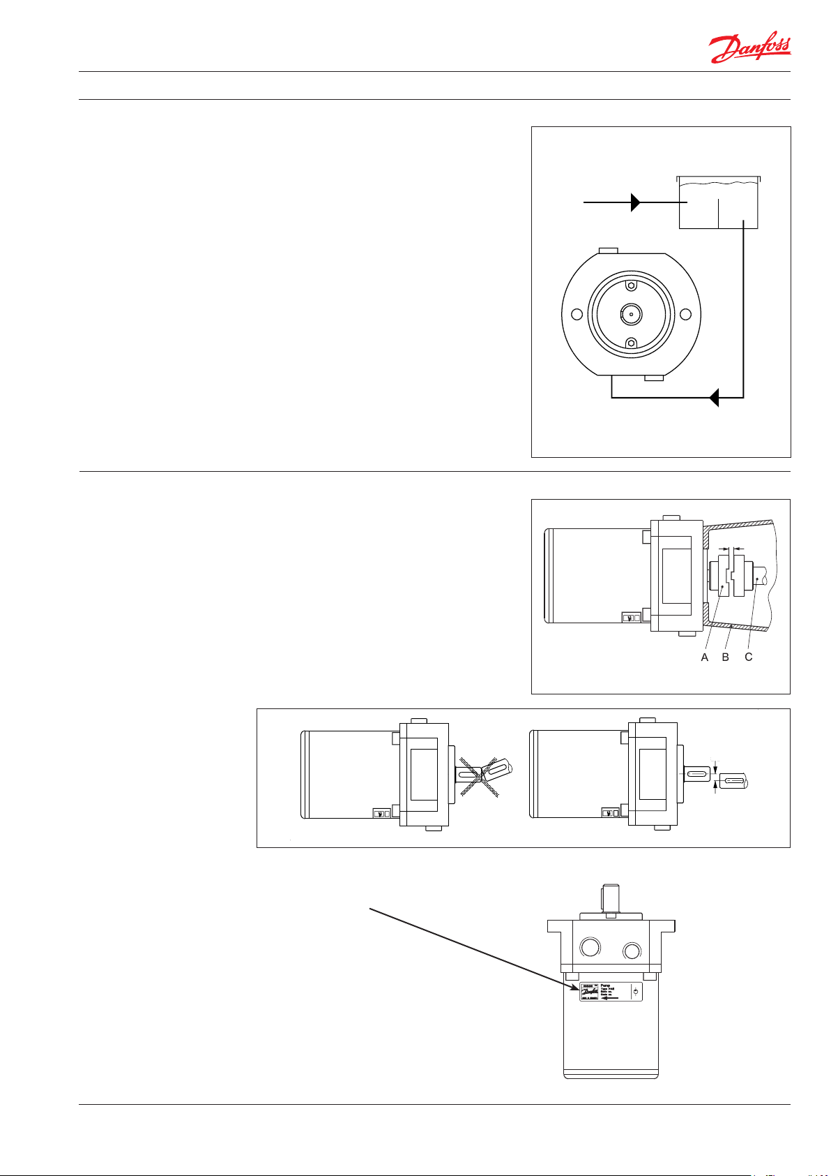
Instruction | APP pump instruction APP 0.6-1.0, APP 1.5-2.5 and APP 3.0-3.5
Automatic pressure equalization between tank
and surroundings must be ensured.
Inlet from the water supply and inlet to the
pump should be placed in opposite ends of the
tank to calm and deaerate the water, and to
ensure optimum opportunity for particles to
settle.
Pump suction line should be placed relatively
high above the tank bottom in order to prevent
settled particles from being led into the pump.
We recommend a separation (“wall”) to separate
the inlet from the outlet end of the tank.
Monitoring
It is recommended to continuously monitor the
following conditions:
• Water level in the tank
• Filter contamination
• Pressure (inlet- and outlet side of the
pump)
3. Building up the pump
unit
3.1 Mounting
(Please also see hints in “Right and Wrong”)
If alternative mounting is desired, please contact
the Danfoss High Pressure Pumps.
Choose proper tolerances to ensure an easy
mounting of the elastic coupling without use of
tools.
Please take care to observe the recommended
length tolerances of the chosen coupling, as an
axial force on the pump will damage the pump.
3.2 Direction of rotation
Is indicated by an arrow at the pump label.
A Elastic coupling
B Bell housing
C Motor shaft
3-5 mm
[0.12-0.2 inch]
max. 0. 25 mm
max. 0.01 in ch
180R9267 | AQ291128576527en-000901 IOM APP 1.5-3.5 Pumps | 12.2021
37
Page 38

Instruction | APP pump instruction APP 0.6-1.0, APP 1.5-2.5 and APP 3.0-3.5
3.3 Orientation
The pump can be mounted/oriented in any
horizontal direction. Vertically only with the shaft
pointing upwards.
3.4 Protection from too high pressures
The pump should be protected against too high
pressure by means of a pressure relief valve or a
bypass/unloading valve placed on the pressure
side.
P Pressure
T Tank
The valve should be placed as close to the pump
as possible. The opening characteristics of the
valve must not result in peak pressures higher
than 200 barg (2900 psig).
The valve outlet must not be connected
directly to the pump suction line. It shall be
connected directly to the tank.
3.5 Connections
O Outlet
I Inlet
C Bleed
D Parallel key 5 × 5 × 20,
DIN 6885
APP 0.6 -1.0 APP 1.5-2.5 and APP 3.0-3.5
O I O I C
Thread size G 1/2 × 13 G 1/2 × 13 G 3/4 x 16 G 3/4 × 16 M6 Hexagon
Max tighten
torque
65 Nm
48 (lbf ft)
65 Nm
48 (lbf ft)
90 Nm
66 (lbf ft)
90 Nm
66 (lbf ft)
5 mm key
5 Nm
3.5 (lbf ft)
38
Contact your fittings supplier for tightening torque requirements. Recommended torque values refer to steel
washers containing a rubber sealing element.
180R9267 | AQ291128576527en-000901 IOM APP 1.5-3.5 Pumps | 12.2021
Page 39
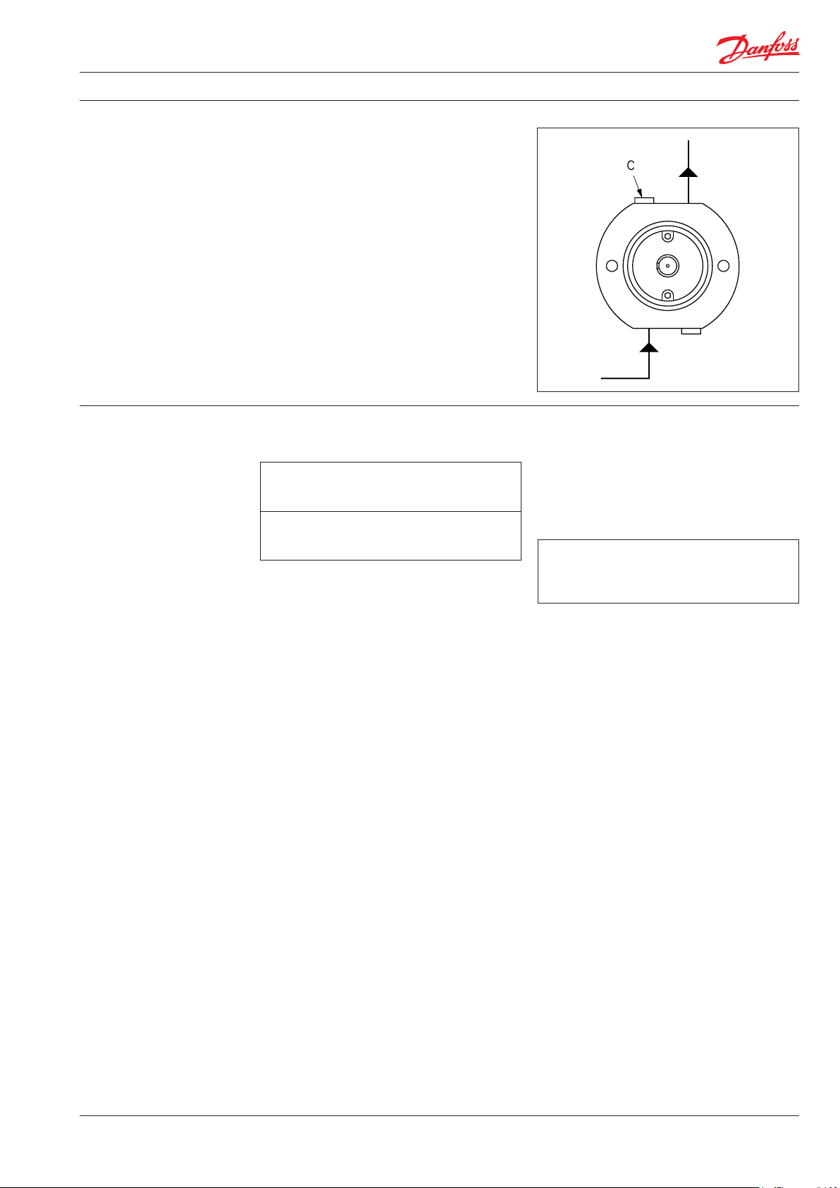
Instruction | APP pump instruction APP 0.6-1.0, APP 1.5-2.5 and APP 3.0-3.5
4. Initial start-up
Before start-up, loosen the top bleeding plug “C”.
When water appears from the bleeding plug,
retighten the plug. With its inlet line connected
to the water supply or the tank, the pump is now
started with open outlet port.
At the initial start of the system, the pump
should be run without pressure for about
5 minutes, thus removing possible impurities
from pipes, hoses, etc. However, the system
should be flushed before start-up – without the
connected pump.
WARNING:
Make sure that the direction of rotation of the
electric motor corresponds to the direction of
rotation of the pump. Otherwise the pump will
be damaged if a check valve is placed between
pump and tank.
5. Operation 5.1 Tem perat ure
Fluid temperature:
Min. +2° C to max. +50° C
Min. +35.6° F to max. +122° F
Ambient temperature:
Min. +2° C to max. +50° C
Min. +35.6° F to max. +122° F
In case of lower operating temperatures, please
contact Danfoss High Pressure Pumps.
C Bleeding plug
When starting up again, follow the bleeding
procedure described under section 4: Initial start
up.
5.5 Storage
Frost protection:
Storage temperature:
Min. -40° C to max. +70° C
Min. -40° F to max. +158° F
5.2 Pressure
The inlet pressure must be min. 0.5 barg
(7.25 psig) and max. 5 barg (72.5 psig). At lower
pressures the pump will cavitate, resulting in
damage to the pump.
Max. pressure on the pump’s outlet line should
be limited at 80 barg (1160 psig) continuously.
Short-term pressure peaks (e.g. in connection
with closing of a valve) of up to 100 barg
(1450 psig) are acceptable.
NB:
The pump unit should include a pressure
gauge on the high pressure side.
5.3 Dry running
When running, the pump must always be
connected to the water supply in order to avoid
damage if it should run dry.
In systems with water tank it is recommended to
build in a level gauge in the tank to avoid the risk
of running dry.
5.4 Disconnection
If the inlet line is disconnected from the water
supply, the pump will be emptied of water
through the disconnected inlet line.
When preparing the pump for long-term storage
or for temperatures below the freezing point,
flush the pump with an anti-freeze medium type
monopropylene glycol to prevent internal
corrosion or frost in the pump.
For further information on anti-freeze media,
please contact Danfoss High Pressure Pumps.
Recommended procedure:
5.5.1 Open-ended systems with water supply
from tank
1. Empty the tank of water and empty the
pump housing through the lower bleeding
plug. When the pump is empty, retighten
the plug.
2. Through the upper bleeding plug, fill the
pump housing with anti-freeze medium.
Pour anti-freeze medium into the tank.
Connect a hose to the outlet of the pump
and lead the other end of the hose back to
tank.
3. Quickly start and stop the pump. Make sure
that the pump does not run dry. The pump
is now protected against internal corrosion
and frost.
180R9267 | AQ291128576527en-000901 IOM APP 1.5-3.5 Pumps | 12.2021
39
Page 40

5.5.2 Open-ended systems with direct water
supply
1. Disconnect the water supply to the pump.
2. Through the lower bleeding plug, empty
the pump housing of water and close it
again.
3. Connect the pump to a tank of e.g. 25 litre
(6 gal.) of anti-freeze additive. Connect a
hose to the inlet port of the pump and via
another hose return the flow from the
outlet port to the tank with anti-freeze
additives.
4. Quickly start and stop the pump. Make sure
that the pump does not run dry. The pump
is now protected against internal corrosion
and frost.
Storage:
Storage of the pump that have been in operation:
For shorter periods of storage flush the pump
with permeate rotating the pump for 10 sec.
empty permeate and store.
For long term storage (more than 2 months)
Danfoss recommends servicing the product and
clean any biological growth of the surfaces. Store
the pump dry without water inside.
6. Service
6.1 Warranty
Danfoss APP pumps are designed for long
operation, low maintenance and reduced
lifecycle costs.
Provided that the pump has been running
according to the Danfoss specifications, Danfoss
guarantees 8,000 hours service-free operation,
however, max. 18 months from date of production. If Danfoss recommendations concerning
system-design are not followed, it will stongly
influence the life of the APP pumps.
6.2 Maintenance
After 8,000 hours of operation, it is recommended to inspect the pump and change any
worn parts, e.g. pistons.
This is done in order to prevent a potential
breakdown on the pump. If the parts are not
replaced, more frequent inspection is recommended according to our guidelines.
Pump shutdown:
The APP pumps are made of Duplex/Super
Duplex materials with excellent corrosion
properties. It is however, always recommended
to flush the pump with fresh water when the
system is shut down.
When stopping the pump for more than 1 day,
flush the pump with permeate by rotating the
pump for 10 sec. Flushing through the flushing
valve of the pump without rotating the pump is
not enough for cleaning the inside of the pump.
The pump can be flushed with biocide like the
membranes. The biocide must be compatible
with the materials used in our pump (materials
can be found in the parts list in the Operating
Guide)
6.3 Repair
In case of irregular function of the APP pump,
please contact Danfoss High Pressure Pumps
sales organisation.
Danfoss A/S
High Pressure Pumps
Nordborgvej 81
DK-6430 Nordborg
Denmark
© Danfoss | DCS (im) | 2019.07
180R9065 | 521B0733 | DKCFN.PI.013.C8.02 | 40
Page 41

Electric Motors
Motor Manual
hoyermotors.com
Page 42

Motor
Manual
General
This manual concerns the following types of standard
induction motors from Hoyer:
HMA3, HMC3, HMA2, HMC2, HMD, HMT, MS, Y2E1, Y2E2, YDT
These motors are manufactured in accordance with IEC/EN
60034-4 and IEC/EN 60072.
Motors are rated for the ambient temperature range -20°C to
+40°C and site altitudes ≤1000 m above sea level.
Low-voltage motors are components for installation in
machinery. They are CE marked according to the Low Voltage
Directive 2014/35/EU.
Motors not fulfilling the IE3 efficiency level must be equipped
with a variable speed drive when used in EU.
Transport and storage
Check the motor for external damage immediately upon
receipt and, if found, inform the forwarding agent right away.
Check all rating plate data, and compare it with the
requirement of the motor.
Turn the shaft by hand to check free rotation, remove
transport locking if used.
Transport locking must be used again for internal transport
also. It is also important that transport locking is used when
motors are transported mounted on equipment.
All motors should be stored indoors, in dry, vibration- and
dust-free conditions.
Lifting eyebolts must be tightened before use. Damaged
eyebolts must not be used, check before use. Lifting eyes at
motor must not be used to lift the motor when it is attached
to other equipment.
Before commissioning, measure the insulation impedance. If
values are ≤ 10MΩ at 25°C, the winding must be oven dried.
The insulation resistance reference is halved for each 20°C
rise in motor temperature.
It is recommended that shafts are rotated periodically by
hand to prevent grease migration.
etc.) using suitable tools, never hit the drive components
with a hammer as this will cause damage to the bearing.
The motor are balancing with half key, ensure that the drive
components are also the same.
Correct alignment is essential to avoid bearing, vibration and
shaft failure.
Use appropriate methods for alignment.
Re-check the alignment after the final tightening of the bolts
or studs.
Check that drain holes and plugs face downwards. We
recommend opening the drain hole for motors placed
outdoors and not running 24 hours / day, so that the motor
can breathe, thus ensuring a dry motor.
Electrical connection
Work is only permitted to be carried out by qualified
specialists and must to be carried out in accordance with
local regulations.
Before work commences, ensure that all power is switched
off and cannot be switched on again. This also applies to the
auxiliary power circuits, e.g. anti-condense heaters.
Check that supply voltage and frequency are the same as
rated data.
Motors can be used with a supply deviation of ± 5% voltage
and ± 2% frequency, according to IEC60034-1.
Connection diagrams for main supply and accessory as PTC
or heater are located inside the terminal box.
Connections must be made in such a way as to ensure that
a permanently safe electrical connection is maintained, both
for the main supply and the earth connection.
We recommend that crimped connections are made in
accordance with IEC 60352-2.
Tightening torques for terminal board screws:
Thread M5 M6 M8 M10 M12 M16 M20 M24
T.(Nm) 2.5 3.5 7 12 18 35 55 80
Installation
The motor must be fixed on a stable, clear and flat foundation.
It must be sufficiently rigid to withstand possible short
circuit forces.
It is important to ensure that the mounting conditions do
not cause resonance with the rotational frequency and the
doubled supply frequency.
Only mount or remove drive components (pulley, coupling,
42
180R9267 | AQ291128576527en-000901 IOM APP 1.5-3.5 Pumps | 12.2021
Ensure that the terminal box is clean and dry.
Unused glands must be closed with blind caps.
Check the terminal box gasket before it is remounted.
Maintenance
Inspect the motor at regular intervals, keep it clean and
ensure free ventilation air flow, check the condition of shaft
seals and replace if necessary. Both electrical and mechanical
Page 43

Motor
Manual
connections must be checked and tightened if necessary.
Bearing size and type are specified on the rating plate. Motor
types HMA3 and HMC3 is as standard with lifetime greased
bearings in motors size ≤180 for cast iron and size ≤132 for
aluminium. Motor types HMA2 and HMC2 is as standard
with lifetime greased bearing in motors size ≤225.
Motor types MS and Y2E is as standard with lifetime greased
bearing in motors size ≤160.
Typical duty hours for lifetime lubricated bearings.
Frame size Poles Typical lifetime
56 - 160 2 - 8 40,000h
180 2 35,000h
200 2 27,000h
225 2 23,000h
180 - 225 4 - 8 40,000h
Motors with a re-greasing system must be lubricated with
high quality lithium complex grease, NLGI grade 2 or 3, with
a temperature range of between -40°C to +150°C.
Motors are normal fitted with a data plate with greasing
information; if it is missing use the following re-greasing
intervals.
Frame
size
160 20 4200 7000 8500 8500
180 20 4200 7000 8500 8500
200 25 3100 6500 8500 8500
225 25 3100 6500 8500 8500
250 35 2000 6000 7000 7000
280 35 2000 6000 7000 7000
315 50 1500 5500 6500 6500
355 60 1000 4000 5000 6000
400 80 800 3000 4000 6000
Grease
(g)
2 pole
(h)
4 pole
(h)
6 pole
(h)
8 pole
(h)
Grease the motor while running, open the grease outlet plug
and let the motor run 1-2 hours before the outlet grease plug
is closed again.
Grease the motor for the first time during commissioning.
The following applies in general for both lifetime lubricated
and re-lubricated bearings:
At 60Hz the time will be reduced by app. 20%.
Data for vertically mounted motors are half of the above
values.
The table values are based on an ambient temperature of
25°C. The values must be halved for every 15K increase in
bearing temperature.
Higher speed operations, e.g. frequency converter drive will
require shorter greasing intervals. Typically, doubling the
speed will reduce the values by 50%.
Special note for Atex Zone 22 and nA motors
Designation of motor according to IEC standard:
II 3D Ex tc IIIB T120°C
II 3G Ex nA IIC T3
The hazardous 3-phase asynchronous motors are in
accordance with International standard IEC 60079-31 and
IEC 60079-15.
Only one electrical installation may be installed in one
specified area (zone).
Only certificated cable glands may be used. Unused glands
must be closed.
Connections must be made in such a way as to ensure that
a permanently safe electrical connection is maintained, both
for the main supply and earth connection.
Installations must be in accordance with actual standards
for installation in hazardours area.
It is recommended that the IEC standard is followed according
to temperature and dust on the motor surface.
The use of motors with so much surface dust that the motor
temperature increases is not permitted.
Regularly cleaning is recommended.
The radial shaft sealing ring is part of the ATEX certification.
It is important that the ring is always intact.
The shaft sealing must be regularly checked, and if dry it
must be lubricated. It is recommended that the seal is relubricated regularly.
Always use the original seal ring when replaced.
Replacing bearings also means replacing the seals.
All machines must be inspected regularly for mechanical
damage.
The user is responsible for changing parts in accordance
with the lifetime of parts, in particular:
bearings, grease and lubrication of shaft sealing.
Maintenance, repairs and replacement on this type must
only be carried out by qualified specialists.
180R9267 | AQ291128576527en-000901 IOM APP 1.5-3.5 Pumps | 12.2021
3
43
Page 44

Connection diagram
Anschlußdiagram
Anslutningdiagramm
Forbindelsesdiagram
Aansluitdiagram
Connection
Conexión
Collegamento
Schemat polacsen
44
180R9267 | AQ291128576527en-000901 IOM APP 1.5-3.5 Pumps | 12.2021
Page 45
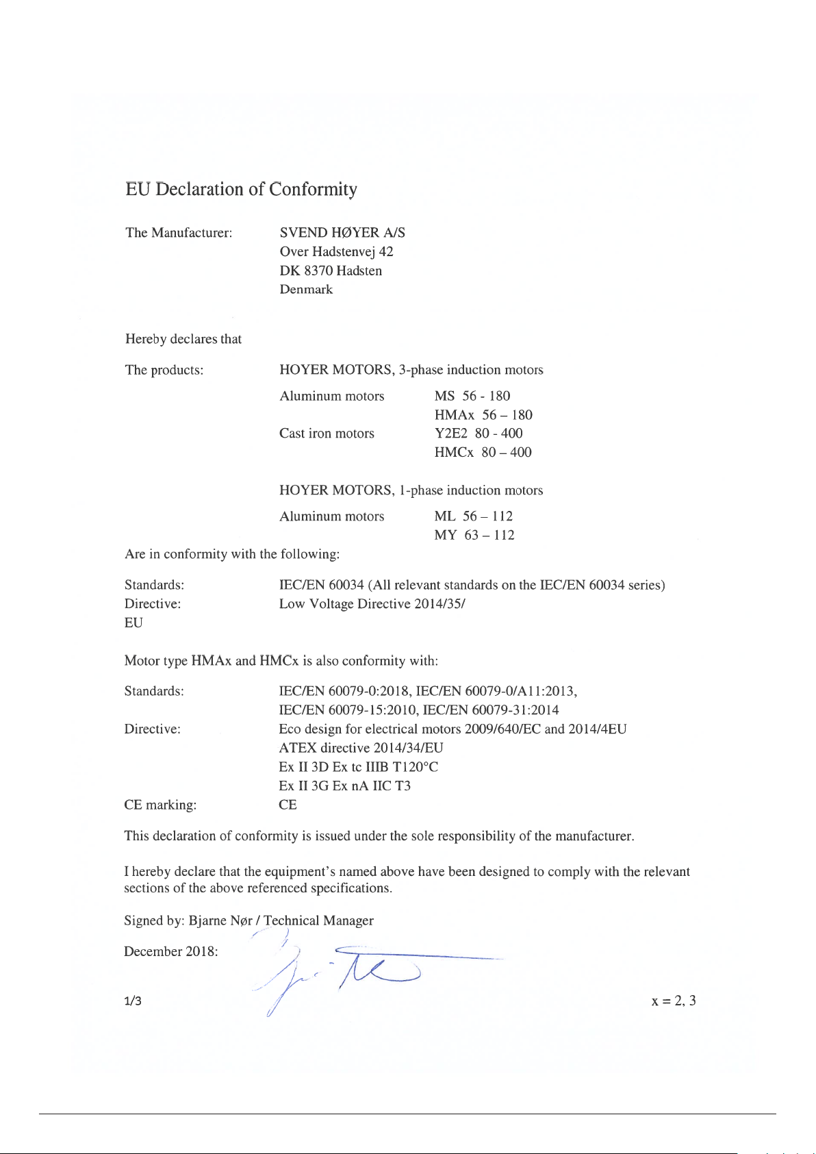
180R9267 | AQ291128576527en-000901 IOM APP 1.5-3.5 Pumps | 12.2021
45
Page 46

Hoyer Motors, Motor Manual, April 2019
Head Offices
Over Hadstenvej 42 · DK-8370 Hadsten
T +45 86 98 21 11 · F +45 86 98 17 79
hoyermotors@hoyermotors.com
19 Jingwu Middle Road · Beilun District
T +86 574 26 28 15 77 · F + 86 574 2628 1573
hoyermotors@hoyermotors.cn
Important notice.
46
Denmark
CVR no. 17 63 06 95
hoyermotors.com
China
Ningbo 315821 · Zhejiang
hoyermotors.cn
Text and data in this catalogue are not binding and we reserve the right to implement changes without further notice.
180R9267 | AQ291128576527en-000901 IOM APP 1.5-3.5 Pumps | 12.2021
Branch Offices
Germany
Landsberger Straße 155 · 80687 München
T +49 89 700 88 235 · F +49 89 543 56 333
germany@hoyermotors.com
hoyermotors.com
Sweden
Liljeholmsstranden 5 · PO box 44017
SE-100 73 Stockholm
T +46 8 446 877 13
sweden@hoyermotors.com
hoyermotors.com
Vasteland 78 · 3011 BN, Rotterdam
Benelux
Tel. +31 10 420 35 20 · Fax.+31 10 420 44 51
benelux@hoyermotors.com
hoyermotors.com
Korea
302ho · Code square · 3150-1 · Daejeo 2-dong
Gangseo-gu · Busan · Korea
T +82 51 996 0251 · F +82 51 996 0252
korea@hoyermotors.com
hoyermotors.com
Page 47
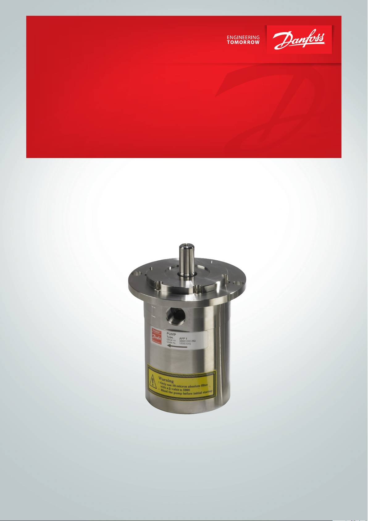
Instruction
Instruction
Recommended service intervals
APP pumps
APP 0.6 - 3.5
for APP 0.6-1.0 / APP 1.5-3.5 /
Recommended service intervals
APP (W) 5.1-10.2 / APP 11-13 / APP 16-22
hpp.danfoss.com
ro-solutions.com
Page 48

Instruction | Recommended service intervals for APP 0.6 - 3.5 pumps
Table of Contents
1. General information....................................................................48
2. Design/features .......................................................................48
3. Appendix 1 ............................................................................49
1. General information This guideline provides information on the
recommended service intervals. The recommendation is based upon good engineering practice
and on experience gained from operation even
under extreme conditions.
2. Design/features Danfoss APP pumps are designed for long
operation and low maintenance and life cycle
costs.
Provided that the pump has been running
according to the Danfoss specifications, Danfoss
guarantees one year service-free operation,
however, max. 18 months from date of
production. After one year of operation it is
recommended to inspect the pump and replace
worn parts, if any.
The recommendation is for guidance only.
If the Danfoss recommendations concerning
system-design (see our data sheet) are not
followed, the service life of the APP pumps might
be affected.
The recommended service intervals on the different parts in the APP pumps appear from the
table below:
* depends on pump size
Pos. Qt y. Description Material Service interval
1 1 Housing, main bearing Duplex, PEEK No need for service
11, 125,
211*
121, 181* 1 Port flange Duplex No wear part
31 1 Swash plate Super Duplex 40,000 hours
66 5/7/ 9 Piston Super Duplex and PEEK Recommended inspection on a
92 1 Valve plate Super Duplex 24,000 hours
91 1 Port plate Super Duplex, PEEK 24,000 hours
61 1 Cylinder barrel Super Duplex 40,000 hours
65 1 Retainer plate Super Duplex 40,000 hours
64 1 Retainer ball Super Duplex 40,000 hours
71 1 Retainer guide Super Duplex 40,000 hours
62 1/4 Spring Duplex 40,000 hours
63 1 Spring guide Duplex or PP 40,000 hours
142 1 Stop for shaft seal PP No wear part
124, 215* 1 Shaft seal Hastelloy and NBR 24,000 hours
125 1 Cover/flange for shaft seal Super Duplex No wear part
93 5/7/9 Back-up ring PTFE 8,000 hours
* O-ring (overall) NBR 8,000 hours
* Screw (overall) AISI 316 8,000 hours
* Pin (overall) AISI 316, Duplex or PEEK No wear part
152 1 Valve cone (flushing valve) Duplex or PEEK 40,000 hours
3, 129 * 2 Bleeding screw Duplex No wear part
67 1 Key AISI 316 40,000 hours
1 Mounting flange/
end flange
Wetted part: Duplex
Dry part: AISI 316L
APP 0.6 - 3. 5
No wear part
yearly basis and evaluated acc.
to app. 1
Replace after 16,000 hrs.
48
180R9267 | AQ291128576527en-000901 IOM APP 1.5-3.5 Pumps | 12.2021
Page 49

Instruction | Recommended service intervals for APP 0.6 - 3.5 pumps
3. Appendix 1 Pistons:
The pistons are the heart of the pump regarding
service.
If the pistons break down, the pump will suffer a
breakdown.
Cavitation of the piston shoes.
New inspection is required in 3,000-4,000 hours.
In case of doubt - the pistons must be replaced.
The pictures below is ment as a guideline for
evaluating the wear of the sliding surface.
Cavitation of the piston shoes.
All pistons must be replaced within the next
500-1,000 hours.
Cavitation of the piston shoes.
All pistons must be replaced within the next
Cavitation of the piston shoes.
All pistons must be replaced immediately.
100-200 hours.
Abrasive wear of the piston shoes.
All pistons must be replaced immediately.
180R9267 | AQ291128576527en-000901 IOM APP 1.5-3.5 Pumps | 12.2021
49
Page 50

© Danfoss | DCS (im | 2021.09
AX290239527130en-000201 | 50
Page 51

Parts list
Parts list
APP pumps
APP Pumps
APP 0.6-46 / APM 0.8-2.9 /
APP 0.6-43 / APM 0.8-2.9 /
APP W 5.1-10.2
APP W 5.1-10.2
hpp.danfoss.com
ro-solutions.com
Page 52

Parts list | APP 0.6-46 / APM 0.8-2.9 / APP (W) 5.1-10.2
Table of Contents
Table of Contents
1. General................................................................................53
4. Parts list APP 1.5-2.5 and APM 1.8-2.9....................................................54
5. Exploded view APP 1.5-2.5 and APM 1.8-2.9 .............................................55
6. Parts list APP 3.0-3.5....................................................................56
7. Exploded view APP 3.0-3.5 .............................................................57
22. Tool sets . . . . . . . . . . . . . . . . . . . . . . . . . . . . . . . . . . . . . . . . . . . . . . . . . . . . . . . . . . . . . . . . . . . . . . . . . . . . . . .58
52
180R9267 | AQ291128576527en-000901 IOM APP 1.5-3.5 Pumps | 12.2021
Page 53

Parts list | APP 0.6-46 / APM 0.8-2.9 / APP (W) 5.1-10.2
1. General
This parts list provides an overview of the
content of the various service sets as well as
explodede views for both non ATEX and ATEX
certified pumps.
ATEX certified pumps are indicated by Ex in the
designation.
No n ATEX AT EX
APP 1.5-2.5 APP 1.5-2.5 Ex
APM 1.8-2.9 N/A
APP 3.0-3.5 APP 3.0-3.5 Ex
180R9267 | AQ291128576527en-000901 IOM APP 1.5-3.5 Pumps | 12.2021
53
Page 54

Parts list | APP 0.6-46 / APM 0.8-2.9 / APP (W) 5.1-10.2
4. Parts list
APP 1.5-2.5 and
APM 1.8-2.9
Note:
The parts listed are not sold separately, only in
various kits
Parts for APM 1.8-2.9 are equivalent to the
parts for APP 1.5-2.5 except for the valve plate
sets.
Exploded view, see next page.
Pos. Qnt. Designation Material
180B4147 – Seal set (APP 1.5-2.5)
180B4146 – Cylinder barrel set (APP 1.5-2.5)
180B4145 – Valve plate set (APP 1.5-2.5)
180F4007 – Valve plate set (APM 1.8 - 2.9)
180B4177 – Retainer set (APP 1.5-1.8 - APM 1.8-2.0)
180B4144 – Retainer set (APP 2.2-2.5 - APM 2.5-2.9)
1 1 Housing Duplex / PEEK
2 1 Pin (Ø4x14) AISI 316 x
61 1 Cylinder barrel Super Duplex / PEEK x
62 1 Spring Duplex x x
63 1 Spring guide PEEK x x
64 1 Retainer ball Super Duplex x x
65 1 Retainer plate Super Duplex x x
66 5 Piston Super Duplex / PEEK x
67 1 Key (5x5x20) AISI 316 x
91 1 Port plate Super Duplex / PEEK x x
92 1 Valve plate Super Duplex x x
93 5 Back-up ring PTFE x x x
94 5 O-ring (Ø13x2) NBR x x x
121 1 Port flange Duplex
122 1 O-ring (Ø83x2) NBR x
123 1 O-ring (Ø40x2) NBR x
124 1 Shaft seal AISI 316 / NBR x
125 1 Mounting flange
126 1 Pin (Ø6x10) PEEK x
127 4 Screw (M6x45) AISI 316 x
128 2 Screw (M6x16) AISI 316 x
129 2 Bleeding plug Duplex x
152 1 Valve cone PEEK x
153 1 Spring Duplex x
154 1 Plug/guide Duplex x
155 1 O -r in g (Ø11.11x1.78 ) NBR x x
1 Instruction x x x x x x x x
Wetted part: PP
Dry part: AISI 316
180B4143 – Piston set (APP 1.5-2.5)
180B4136 – Flushing valve set (APP 1.5 - 3.5)
54
180R9267 | AQ291128576527en-000901 IOM APP 1.5-3.5 Pumps | 12.2021
Page 55

Parts list | APP 0.6-46 / APM 0.8-2.9 / APP (W) 5.1-10.2
5. Exploded view
APP 1.5-2.5 and APM 1.8-2.9
[2.95 lbf ft
± 0.74 lbf ft]
[8.8 5 lbf ft
± 2.21 lbf ft]
180R9267 | AQ291128576527en-000901 IOM APP 1.5-3.5 Pumps | 12.2021
[2.95 lbf ft ± 0.74 lbf ft]
55
Page 56

Parts list | APP 0.6-46 / APM 0.8-2.9 / APP (W) 5.1-10.2
6. Parts list
APP 3.0-3.5
Note:
The parts listed are not sold separately, only in
various kits.
Exploded view, see next page.
Pos. Qnt. Designation Material
180B4153 – Seal set (APP 3.0-3.5)
180B4152 – Cylinder barrel set (APP 3.0-3.5)
180B4151 – Valve plate set (APP 3.0-3.5)
180B4150 – Retainer set (APP 3.0-3.5)
180B4149 – Piston set (APP 3.0-3.5)
180B4134 – Swash plate set (APP 3.0)
1 1 Housing Duplex / PEEK
2 1 Pin (Ø4x14) AISI 316 x
31 1 Swash plate Super Duplex x x
32 1 Centre bolt Duplex x x
33 1 Pin (Ø 6x10) PEEK x x x
61 1 Cylinder barrel Super Duplex / PEEK x
62 1 Spring Duplex x
63 1 Spring guide PEEK x
64 1 Retainer ball Super Duplex x
65 1 Retainer plate Super Duplex x
66 7 Piston Super Duplex / PEEK x
67 1 Key (5x5x20) AISI 316 x
91 1 Port plate Super Duplex / PEEK x
92 1 Valve plate Super Duplex x
93 7 Back-up ring PTFE x x
94 7 O-ring (Ø13x2.0) NBR x x
121 1 Port flange Duplex
122 1 O-ring (Ø83x2) NBR x
123 1 O-ring (Ø40x2) NBR x
124 1 Shaft seal AISI 316 / NBR x
125 1 Mounting flange
126 1 Pin (Ø4x9) PEEK x
127 4 Screw (M6x45) AISI 316 x
128 2 Screw (M6x16) AISI 316 x
129 2 Bleeding plug Duplex x
130 2 O-ring (Ø4.5x1.5) NBR x
152 1 Valve cone PEEK x
153 1 Spring Duplex x
154 1 Plug/guide Duplex x
155 1 O -r ing (Ø11.11x1.7 8) NBR x x
Instruction x x x x x x x x
Wetted parts: PP
Dry parts: AISI 316L
180B4135 – Swash plate set (APP 3.5)
180B4136 – Flushing valve set (APP 3.5)
56
180R9267 | AQ291128576527en-000901 IOM APP 1.5-3.5 Pumps | 12.2021
Page 57

Parts list | APP 0.6-46 / APM 0.8-2.9 / APP (W) 5.1-10.2
7. Exploded view
APP 3.0-3.5
180R9267 | AQ291128576527en-000901 IOM APP 1.5-3.5 Pumps | 12.2021
57
Page 58

Parts list | APP 0.6-46 / APM 0.8-2.9 / APP (W) 5.1-10.2
22. Tool sets
Note:
The parts listed are not sold
separately, only in various kits.
Designation
Shaft bush
Press bush
Drift
Tor x (T 30)
Shaft bush (Ø18) x
Press bush (Ø18) x
Allen key (4 mm)
Allen key (5 mm) x
Allen key (6 mm)
Shaft bush (Ø35)
Shaft seal extractor (Ø35)
Press bush (Ø35)
Adjustable pin wrench
Combination wrench (10 mm)
Combination wrench (13 mm)
Nut (M8x6.5x13)
Guide bolt (M8x140)
Shaft seal extractor (Ø45)
Press bush (Ø45)
Eye bolt (M8)
Press bush for valve plate
Stop for retainer plate
Screw (M8x20)
Screw (M8x70)
180B4148 – Tool set (APP 1.5-3.5)
58
180R9267 | AQ291128576527en-000901 IOM APP 1.5-3.5 Pumps | 12.2021
Page 59

Parts list | APP 0.6-46 / APM 0.8-2.9 / APP (W) 5.1-10.2
180R9267 | AQ291128576527en-000901 IOM APP 1.5-3.5 Pumps | 12.2021
59
Page 60

Danfoss A/S
High Pressure Pumps
Nordborgvej 81
DK-6430 Nordborg
Denmark
© Danfoss | DCS (im) | 2018.11
AX274346749037en-000401 | 60
Page 61
Guideline
Trouble shooting guide
APP, APP S and APP S 674 pumps
ro-solutions.com
Page 62

Instruction | Trouble shooting guide for APP, APP S and APP S 674 pumps
Table of contents
Trouble shooting fish bone chart .......................................................63
2. Reduced flow/reduced pressure ........................................................65
3. High torque on electric motor ..........................................................66
6.1 Valve plate.............................................................................69
6.2 Port plate ..............................................................................70
6.3 Swash plate............................................................................70
62 | © Danfoss | DCS (im) | 2021.12
180R9267 | AQ291128576527en-000901 IOM APP 1.5-3.5 Pumps
Page 63

Instruction | Trouble shooting guide for APP, APP S and APP S 674 pumps
Trouble shooting
fish bone chart
PUMP FAILED
2. Reduced ow/pressure
(hoses/pipes)
inlet/outlet line
2.3 RPM
2.2 Low inlet pressure
2.1.5 Pre-treatment
2.1.6 Main ltration
2.1.8 High uid temperature
2.1.7 Fluid type
(internal leakage)
2.1 Wear in pump
1. No ow/pressure
5.1 Inlet/outlet connections
5.2 Length/dimensions of
4.1 Air in uid
4.2 Bleeding conditions of pump
directly on frame
5.3 Hose stiness
inlet pressure
4.3 Min/max nominal
electric motor
5.4 Hoses/pipes mounted
5.5 Vibration damper und er the
4.4 Pump reversin g
4.5 High rot ation speed (RPM)
4.6 Outlet pressure
5. Noise from installation
4. Noise from pump
4.7 Soft sta rt/stop
© Danfoss | DCS (im) | 2021.12
1.6 Pump damage
1.5 Axial force o n pump shaft
1.4 No rotation of pump
1.3 No rotation of e lectric motor
1.2 Pump reversing
1.1 Dry running
from pump
3.1 Too high outlet pressure
3.2 Pump starts against pressure
3.3 Constant torque
3.4 Water pump damage
3. High torque on el. motor
180R9267 | AQ291128576527en-000901 IOM APP 1.5-3.5 Pumps | 63
Page 64

Instruction | Trouble shooting guide for APP, APP S and APP S 674 pumps
Cause Remedy Comments
1.1 Dry running
(no water supply to the pump)
1.2 Pump reversing
(electric motor is running the wrong direction,
i.e. counter-clockwise)
If no water comes out of the pump:
1.1.1 Check that inlet valve is open.
1.1.2 Check that booster pump is running.
1.2.1 Change the phase on the electric motor to
make it run clockwise.
WARNING:
- The pump must not run without water for
more than a few seconds.
- If the pump takes in water from the high-
pressure outlet line, it builds up pressure in
pump housing and will eventually break
down.
Mount a low pressure switch in front of the
pump and check its set point/ function. The low
pressure switch ensures that the pump does
not start until the inlet pressure has reachedminimum inlet pressure (see User manual).
Rotation direction for the APP, APP S or APP S 674
pump is shown by an arrow on the label on the
pump.
1.3 No rotation of electric motor 1.3.1 Check that main switch is switched on.
1.4 No rotation of pump 1.4.1 Ensure that coupling between electric
1.5 Axial load on pump shaft
(may cause high internal leakage)
Only applying to
APP 0.6 to APP 3.5 and
APP 21 to APP 26 only.
Also applying to APP S and APP S 674 pumps.
1.3.2 Check the electricity at the facility.
1.3.3 Ensure that motor relay is switched on.
1.3.4 Ensure that fuse is not blown.
1.3.5 Ensure that booster pump is started.
1.3.6 Check that the monitor switches are
working correctly.
1.3.7 Disconnect pump from electric motor and
check that the motor is capable of running
with no load.
motor and pump is connected.
1.4.2 Check if coupling is damaged.
1.4.3 Check that electric motor is sized correctly.
1.4.4 Check that the electrical installation is
correctly sized.
1.4.5 Contact Danfoss Sales office for guidelines
in how to troubleshoot internal pump
parts.
1.5.1 Ensure that the air gap between the two
coupling parts is min 5 mm. It should
always be possible to move the plastic part
on the coupling at least 3 mm.
If motor-type relay or the electrical fuse is
blown, check that electric motor is sized
correctly.
To ensure easy mounting of the flexible
coupling without using tools, the tolerances
must be dimensioned accordingly.
WARNING:
Any axial and/or radial loads on the shaft
must be avoided. Any axial or radial load will
cause breakdown.
A - Bell housing
B - Flexible coupling
C - Motor shaft
1.6 Pump damage
(the internal parts may be damaged)
64 | © Danfoss | DCS (im) | 2021.12
1.6.1 Contact Danfoss sales office for guidelines
in how to troubleshoot internal pump
parts.
180R9267 | AQ291128576527en-000901 IOM APP 1.5-3.5 Pumps
A B C
Instructions on internal elements
– are available on hpp.danfoss.com.
Page 65

Instruction | Trouble shooting guide for APP, APP S and APP S 674 pumps
2. Reduced flow/reduced pressure
Cause Remedy Comments
2.1 Wear on pump
Large internal leakage due to:
2.1.1 Dismantle the pump.
2.1.2 Check valve plate.
Valve plate has marks/scratches on the
surface facing the port plate. Minor wear
on valve plate can cause large internal
leakage. See Index 6.1.
2.1.3 Check port plate.
Port plate has marks/scratches on the
surface facing the valve plate. Minor wear
on port plate can cause large internal
leakage. See Index 6.2.
2.1.4 Check cylinder barrel.
Liners in cylinder barrel may be scratched
or worn. Insert a piston in the liner and
check the fit. If there is any space
(clearance) between liner and piston, liner
or piston is worn.
2.1.5 Pre-treatment
Analyse fluid for content of particles.
- Check that filters are OK and working
correctly.
2.1.6 Main filtration
Check that the correct filter type is used
(particles in fluid must not exceed 10 μm).
Danfoss High Pressure Pumps supplies
filters, please contact the sales office.
Typical signs of wear:
Polished surface all over the swash plate.
Normally, only half of the swash plate = the
pressure side is polished. See index 6.3.
If the ring is missing, the piston is very worn.
The filters can be bypassed, even if they are
correctly mounted. Some filters can create
channelling where particles can pass through
the filter in tunnels. String wounded filters are
typically channelling filters. A string wounded
filter may have a filtration efficiency of only
50%, which will cause internal wear and must
always be followed by a main filter.
2.1.7 Fluid type
The APP, APP S and APP S 674 pumps are
designed for seawater operation; for any
other fluid, please contact Danfoss High
Pressure Pumps sales office for further help.
-
2.2 Low inlet pressure 2.2.1 Check that booster pump supplies the
2.3 Rotation speed (rpm) 2.3.1 If VFD-operated, check frequency.
2.1.8 High fluid temperature
If fluid temperature is above 50 °C (122 ° F),
stop the pump immediately.
- Check internal parts (see above).
right pressure/flow.
2.2.2 Check if filters require replacement.
2.3.2 Check that rotation speed of the electric
motor is as stated on name plate on
electric motor. Check that the motor rotor
winding is not damaged.
Insufficient filtration means that too many or
too large hard particles can pass the main filter
because it is damaged, bypassed or simply too
poor. Filtration efficiency must be 99.98%
(Beta = 5000) at 10 μm to prevent abnormal
wear of the pump.
Temperature > 50 °C (122 ° F) will cause wear on
internal pump parts. Mount a temperature
switch and check its set point / function. The
temperature switch will ensure that the pump
stops at fluid temperatures > 50 °C (122 ° F).
If the pressure drop across the filters is too high,
the booster pump does not deliver sufficient
flow/pressure. No pressure or low pressure
results in cavitation and insufficient internal
lubrication causing wear on internal pump
parts.
Mount a low-pressure switch in front of the
pump and check its set point/ function. The
low- pressure switch ensures that the pump
does not start until the inlet pressure has
reached 1 bar.
Speeds below min. limit (see User manual)
result in insufficient internal lubrication causing
wear on the internal pump parts.
© Danfoss | DCS (im) | 2021.12
180R9267 | AQ291128576527en-000901 IOM APP 1.5-3.5 Pumps | 65
Page 66
Instruction | Trouble shooting guide for APP, APP S and APP S 674 pumps
3. High torque on electric motor
Cause Remedy Comments
3.1 Too high outlet pressure from pump 3.1.1 Check fluid salinity.
3.1.2 Check temperature.
3.1.3 Check pressure drop across RO membrane.
3.2 Pump starts against pressure 3.2.1 Check that electric motor is correctly sized.
3.2.2 Check internal parts (see item 2.1).
3.2.3 Systems with more than one electric
motor installed:
Start motors simultaneously.
3.3 Constant torque 3.3.1 Please contact Danfoss High Pressure
Pumps sales office.
3.4 Water pump damage 3.4.1 Dismantle pump and check for wear. Too heavy damage in the pump will increase
Pump conditions may change (more salt, lower
water temperature or scaling of RO membrane)
causing higher pressure, resulting in higher
motor torque.
Pumps run in parallel with cascade start, may
switch off the motor relay due to too high
torque caused by high outlet pressure.
If the electric motor is too small for the APP, APP S
or APP S 674 pump, it cannot provide sufficient
torque.
friction causing a high torque (see item 6,
Typical signs of wear).
66 | © Danfoss | DCS (im) | 2021.12
180R9267 | AQ291128576527en-000901 IOM APP 1.5-3.5 Pumps
Page 67

Instruction | Trouble shooting guide for APP, APP S and APP S 674 pumps
Cause Remedy Comments
4.1 Air in fluid 4.1.1 Ensure that the entire inlet line is bled
before starting up the system.
4.1.2 Ensure that air cannot enter into the inlet
line.
4.2 Bleeding conditions of pump 4.2.1 Follow the instructions “Initial start-up”
supplied with the new pump.
4.2.2 Ensure that the pump is completely bled
before start-up.
4.3 Min/max nominal inlet pressure 4.3.1 Ensure that inlet pressure is within the
limits specified in the User manual.
4.3.2 Check the pump for internal damage.
4.4 Pump reversing 4.4.1 Dismantle pump and check if anything is
broken or worn (See “1. No flow”, item 1.2
Pump reversing”).
WARNING:
The pump must not run without water
for more than a few seconds. If the pump
takes in water from the high-pressure
outlet line, it builds up pressure and will
eventually be damaged.
4.5 High rotation speed (rpm) 4.5.1 If electric motor rpm is too high, dismantle
pump and check for damage.
4.5.2 If the rpm is within the specified range of
the pump data sheet and abnormal noise
remains, dismantle pump and check for
damage.
Small air bubbles will accumulate and create
large bubbles causing internal cavitation and
thus making the pump very noisy.
WARNING:
The pump can only run few minutes with air
in
the fluid without being damaged.
The pump and the inlet line must be completely bled before start-up, otherwise the
pump will cavitate and make high noise.
WARNING:
The pump can only run few minutes with air
in the fluid without being damaged.
Too high inlet pressure causes too high
pressure inside the pump damaging the pistons
and eventually the pump.
Inlet pressure below min. limit causes
cavitation and insufficient internal lubrication
resulting in wear on internal pump parts.
Mount a low-pressure switch in front of the
pump and check its set point/ function. The
low-pressure switch will ensure that the pump
does not start until the min. inlet pressure has
been reached.
If pump rotates in wrong direction, it will take
in water from the high-pressure outlet line.
Pressure will be built up inside the pump and it
will eventually be damaged.
Higher rpm than specified in the pump data
sheet results in wear of the pistons, i.e. pistons
may be damaged.
High rpm will also increase pressure pulsations
from the pump, and the noise level will
increase.
4.6 Outlet pressure 4.6.1 If outlet pressure is too low, check set
point of outlet pressure valve.
4.6.2 If outlet pressure is lower than mentioned
in the pump data sheet, please contact
Danfoss High Pressure Pumps technical
support.
4.6.3 If outlet pressure has exceeded its
maximum, check set point of outlet
pressure valve.
4.6.4 Check internal parts for wear/damage.
4.7 Soft start/stop 4.7.1 Check if noise is normal when the pump is
running at operation speed.
4.7.2 If noise is abnormal at operation speed,
check internal parts (see above).
© Danfoss | DCS (im) | 2021.12
180R9267 | AQ291128576527en-000901 IOM APP 1.5-3.5 Pumps | 67
If rpm is changed, noise frequency will also
change.
At too low outlet pressure, the pump will create
higher pressure pulsations and thus make
noise. Too low pressure also causes insufficient
internal lubrication and wear on internal parts.
Pump may eventually be damaged.
Too high outlet pressure may damage the
pump.
Noise frequency changes during soft start-up/
stop.
Page 68

Instruction | Trouble shooting guide for APP, APP S and APP S 674 pumps
Cause Remedy Comments
5.1 Inlet/outlet connections (hoses/pipes) 5.1.1 Use flexible hoses at inlet/outlet connec-
5.2 Length/dimension of inlet/outlet line 5.2.1 Increase pipe diameter and/or reduce the
5.3 Hose stiffness 5.3.1 Use a more flexible hose. Danfoss can
5.4 Hoses/pipes mounted directly on frame 5.4.1 Mount the connections to the frame by a
5.5 Vibration dampener under the electric
motor
tions. Danfoss can provide flexible hoses.
Please contact Danfoss High Pressure
Pumps sales office for further information.
5.1.2 Mount the connections to the frame by a
vibration dampener mounting plate.
number of bends.
provide flexible hoses. Please contact
Danfoss High Pressure Pumps sales office
for further information.
vibration dampener mounting plate.
5.5.1 Mount a vibration dampener below the
motor/pump.
Non-flexible connections mounted directly on
the frame will cause even small pressure
pulsations from pump and create vibrations in
the system/plant.
Too small pipes or too many bends may create
too fast flow/turbulence through the pipes and
thus increase the noise level.
Too stiff hoses cannot dampen the small
pressure pulsations from the pump, and
subsequently vibrations occur in the system/
plant.
If the hoses are mounted directly on the frame,
the small pressure pulsations from the pump
can be transferred to the frame and the rest of
the system/plant.
When no dampener is installed below the
electric motor, vibrations from the motor and
pump may be transferred to the frame and the
rest of the system/plant.
68 | © Danfoss | DCS (im) | 2021.12
180R9267 | AQ291128576527en-000901 IOM APP 1.5-3.5 Pumps
Page 69

Instruction | Trouble shooting guide for APP, APP S and APP S 674 pumps
6.1 Valve plate
Picture 1
Picture 2
Scratches
A normally worn valve plate has no marks/scratches but only a slightly
polished surface.
No scratches or marks should be felt. The surface must be flat and level.
A worn valve plate has scratches, and/or a polished surface. Even small
scratches will give a loss of flow.
Picture 3 A good way to identify a worn valve plate is to hold a straight knife edge
over the valve plate. When holding it up to the light, it will be possible to
see any space between the knife edge and the valve plate. See picture 3.
If any light can be seen between the two arrows on the picture, the valve
plate is worn.
If any scratches or ma rks can be felt by runnin g a fingernail over the surfa ce,
the valve plate is worn.
The valve plate on picture 3 is highly damaged.
© Danfoss | DCS (im) | 2021.12
180R9267 | AQ291128576527en-000901 IOM APP 1.5-3.5 Pumps | 69
Page 70

Instruction | Trouble shooting guide for APP, APP S and APP S 674 pumps
6.2 Port plate
Picture 1
6.3 Swash plate
Picture 1
Scratches
Level differences between
dull and shining PEEK
If the por t plate has scratches, level diffe rences or both betwe en the arrows,
the port plate must be replaced.
Even small scratches or wear will cause loss of flow.
To check: See item 6.1, picture 3.
If the swash pla te is polished 360°, it is an indication o f insufficient filtration.
The surface of the swash plate must be plane and even at same level all
over. To check this, please see item 6.1, picture 3.
If the surface has any marks/scratches, it is worn/damaged and a new one
is required.
Please contact Danfoss High Pressure Pumps sales office for further information.
70 | © Danfoss | DCS (im) | 2021.12
180R9267 | AQ291128576527en-000901 IOM APP 1.5-3.5 Pumps
Page 71

Instruction | Trouble shooting guide for APP, APP S and APP S 674 pumps
© Danfoss | DCS (im) | 2021.12
180R9267 | AQ291128576527en-000901 IOM APP 1.5-3.5 Pumps | 71
Page 72

Danfoss A/S
High Pressure Pumps
DK-6430 Nordborg
Denmark
© Danfoss | DCS (im) | 2015.12
72
Page 73

.
Right and wrong
Right and Wrong
Trouble shooting guide for water hydraulic systems
Trouble shooting guide for
water hydraulic systems
hpp.danfoss.com
Page 74

Design
4.
Pump location
1.
.
.
Choice of material
Rubber
Plastic
. Stainless steel
Always use system components made
of corrosion proof materials
2.
Non-corrosion proof materials
may cause damage
Choice of filter
.
Iron
.
Copper
. Brass
. Aluminium
Pump always to be placed below water
surface level
5.
System to be dimensioned to provide
a suction pressure of the pump inlet of
max. 0.1 bar vacuum
6.
Suction conditions
Pressure Relief valve
Pump location above water surface
level will cause damage
Poor suction conditions will cause
malfunction and damage the pump
< 10 mm abs.
Install a 10 micron absolute filter with
pressure switch
3.
Locate the return filter in the return line
immediately before the tank
Filter location
> 10 mm
Return filter with bypass valve and
poorer filterability than 10 m will
damage the system
Placing the return filter upstream of the
final load may damage the pump
Pressure relief valve to be mounted
vertically or with vertical outlet and
connected to return hose or tank
7.
System to be filled via filter
Coupling the pressure relief valve outlet
directly to the pump inlet may damage
the pump
Water supply
Filling system with unfiltered
water causes damage
Page 75

Installation
8.
Prior to installation, burrs and chips and
other impurities must be removed from
pipes and hoses, eg with a felt plug
9.
Impurities
Chips or other impurities in the system
may cause damage
Sealing
11.
The coupling must be easy and simple
to assemble (see product instruction)
Assembly of coupling
12.
= min. 3 mm
Never use force when assembling the
coupling parts, as this will damage the
motor/pump
Coupling
0 mm
Fittings in screwed components to be
sealed with O-rings or bonded seals
10.
Correctly limited quantities of grease
prevent seizing
Using teflon tape or packing yarn in
joints may cause damage
Grease
Too much grease may develop
biofilm causing operational failures
Ensure always to have 3 mm distance
between coupling flanges
13.
Fill system with water before starting
to ensure lubrication and cooling
Insufficient distance and/or misalignment between the coupling flanges
will damage the pump
Water supply
Starting without water will cause
damage
Page 76
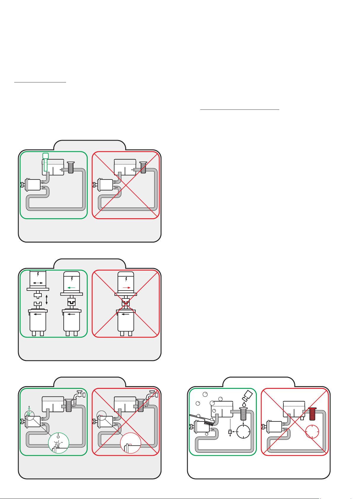
Wiring
Starting procedure
Cleaning procedure
14.
Level and temperature indicators
must be fitted. Follow installation
instructions
15.
1
?
2
Level indicator
Missing or incorrectly connected level
and temperature indicators cause
damage
Rotation direction
1. Fill cold water into the system via the return filter and
bleed the pump (Power Packs PPH 4 - 6.3 - 10 and 12.5 are
self-bleeding)
2. Start and bleed the system -without pressure by opening
the bypass valve
3. Add the cleaning agent to give 3% agent/water solution
4. Run the system for 60 min. and activate all components as
often as possible to ensure effective flushing with the
cleaning agent
5. Empty the system of the cleaning agent solution
Flushing procedure
6. Fill cold water through the return filter and bleed the
pump (Power Packs PPH 4 - 6.3 - 10 and 12.5 are
self-bleeding)
7. Run the system for 30 min. and activate all components as
often as possible
8. Empty the system of the water
Check pump drive motor rotation
direction matches that of the pump
prior to installation
16.
Bleeding the pump will ensure correct
cooling and lubrication
Incorrect rotation direction will
damage the pump
Bleeding
Insufficient bleeding may cause damage (not applicable to Power Packs)
9. Alternatively the system may be flushed by running the
unit without the return hose while continuously filling up
water. The flushing should continue until there is no trace
of cleaning agent in the return water
10. Change the return filter element, fill cold water through
the return filter and bleed the pump during start up
11. The system is now ready for operation
Starting procedure
60 min.
Observing the starting procedure will
ensure problem-free operation
If the system is not cleaned before
starting, the filter will clog
2-3
days
Page 77

Trouble shooting
Open ended water systems
.
No
.
No water supply
Is the water supply ok?
Is water supplied to the pump?
Yes
.
Is water coming
out of the tap?
No
.
Are all taps open?
.
Is the control light
for “low pump suction
Yes
pressure” on?
.
The filter is clogging
.
Is water coming
through the filter?
.
Replace filter element
Yes
No
No
Yes
.
Is the electric motor of
the pump unit rotating?
Yes
No
.
Is the water in the tank
very hot? Ie above 50
No
.
Is the power supply ok?
.
Are control lights on?
Yes
.
Is the filter clogged?
No
.
Is the filter control
light on?
Yes
.
Replace filter element
.
Yes
o
No
Lower inlet
temperature or
provide better cooling
.
A blown fuse / or short
circuit?
. Check power supply
and fuses and contact
electrician
.
Turn on the tap for
water supply
Contact serviceman
Stamp
Page 78

Trouble shooting
Closed water systems
.
Is there sufficient water
No
in the tank?
Yes
The system
does not work
.
Fill water into the system
.
Is the electric motor of
the pump unit rotating?
Yes
No
.
A blown fuse/or short
circuit?
. Check power supply
and fuses and contact
electrician
.
Is the water in the tank
very hot? Ie above 50
.
Is the power supply ok?
No
.
Are control lights on?
Yes
.
Is the filter clogged?
.
Is the filter control
light on?
Contact serviceman
No
No
Yes
o
.
At temperatures
higher than 50o the
pump drive cuts out.
Consequently the
cooler must be
checked/cleaned
Yes
.
Replace filter element
.
Trace leakage, if any
Stamp
Page 79

Page 80

© Danfoss | DCS (im) | 2021.12
180R9267 | AQ291128576527en-000901 IOM APP 1.5-3.5 Pumps | 80
 Loading...