

Page 1
Data sheet
Data sheet
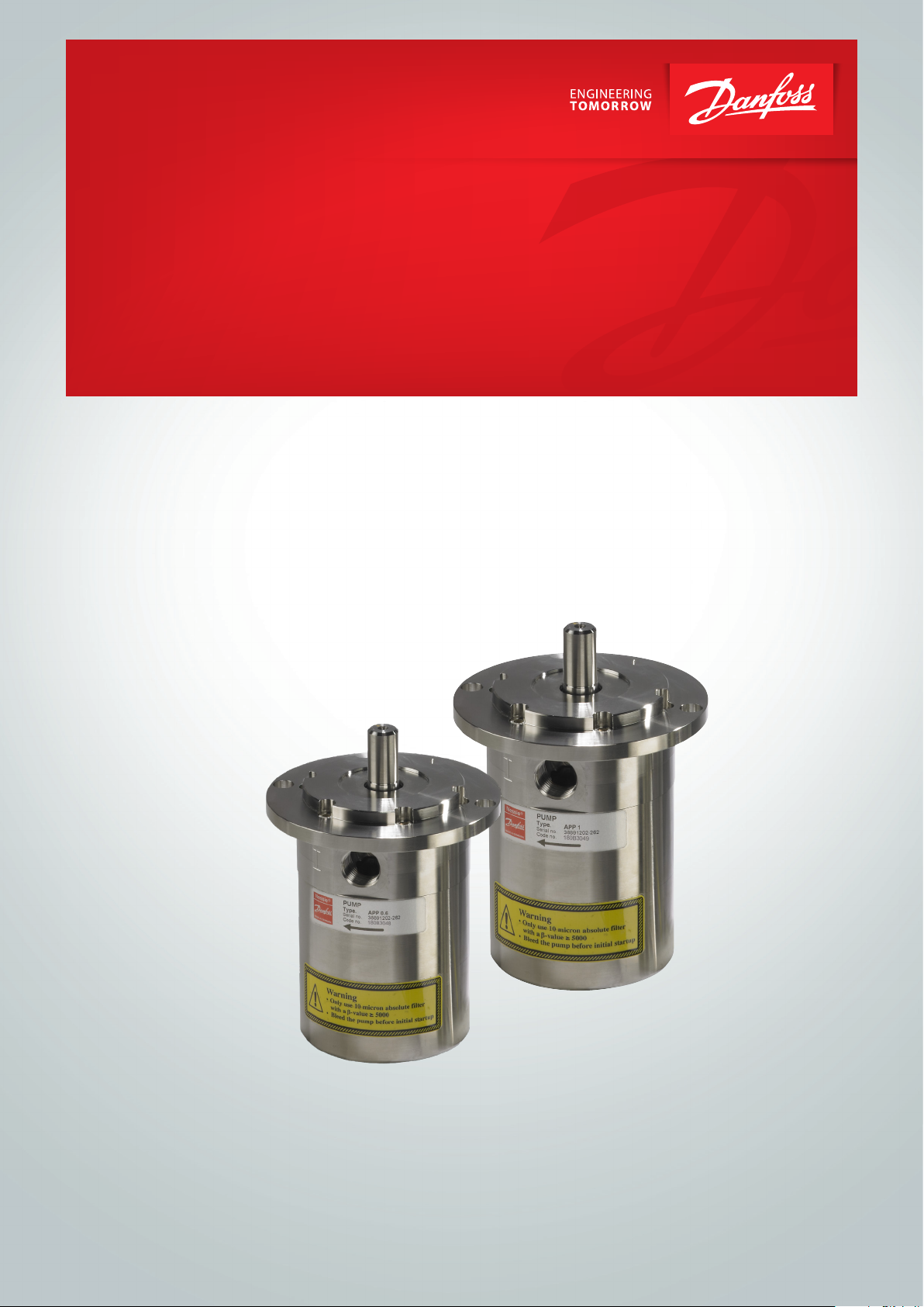
APP pumps
APM motor
APM 0.8 / APM 1.0 / APM 1.2 /
APP 0.6-1.0 / APP 1.5-3.5 / APP (W) 5.1-10.2 /
APM 1.8 / APM 2.0 / APM 2.5 / APM 2.9
for energy recovery
APP 11-13 / APP 16-22 / APP 21-43
hpp.danfoss.com.
ro-solutions.com
Page 2

Data sheet | APM 0.8 – 2.9 motors
Table of Contents
1. Introduction ............................................................................3
2. Benets.................................................................................3
3. Technical data ..........................................................................4
3.1 APM 0.8 – 1.2............................................................................4
3.2 APM 1.8 – 2.9............................................................................5
4. Direction of rotation ...................................................................6
5. Shaft load...............................................................................6
6. Temperature and corrosion..............................................................7
7. Noise level ..............................................................................7
8. Filtration................................................................................7
9. Orientation .............................................................................8
10. Installation..............................................................................8
11. Preferred system design.................................................................9
11.1 Membrane system with energy recovery ...............................................10
11.2 Membrane system with energy recovery and VFD.......................................11
12. Combinations..........................................................................12
12.1 Examples of motor / pump combinations...............................................12
12.2 Flow ...................................................................................12
12.3 Energy consumption vs. pressure.......................................................13
12.4 Power consumption....................................................................13
13. Dimensions ............................................................................14
13.1 APM 0.8 – 1.2...........................................................................14
13.2 APM 1.8 – 2.9...........................................................................15
14. Service.................................................................................16
2 | Danfoss | DCS im) |2020.09
AI354846545311en-000101
Page 3
Data sheet | APM 0.8 – 2.9 motors
1. Introduction
APM motors are designed for energy recovery
systems together with an APP hydraulic pump
and a double shaft motor. APM motors convert
hydraulic energy (pressure, ow) to mechanical
energy (torque, speed).
This data sheet is valid for APM hydraulic motors.
APM hydraulic motors are build to operate on
salt water and are based on the axial piston
principle with xed displacement, enabling a
very light and compact design. Lubrication of the
moving parts is provided by the salt water itself.
Shaft speed is proportional to the input ow.
The APM motor is not self-starting but needs a
rotational force to start turning.
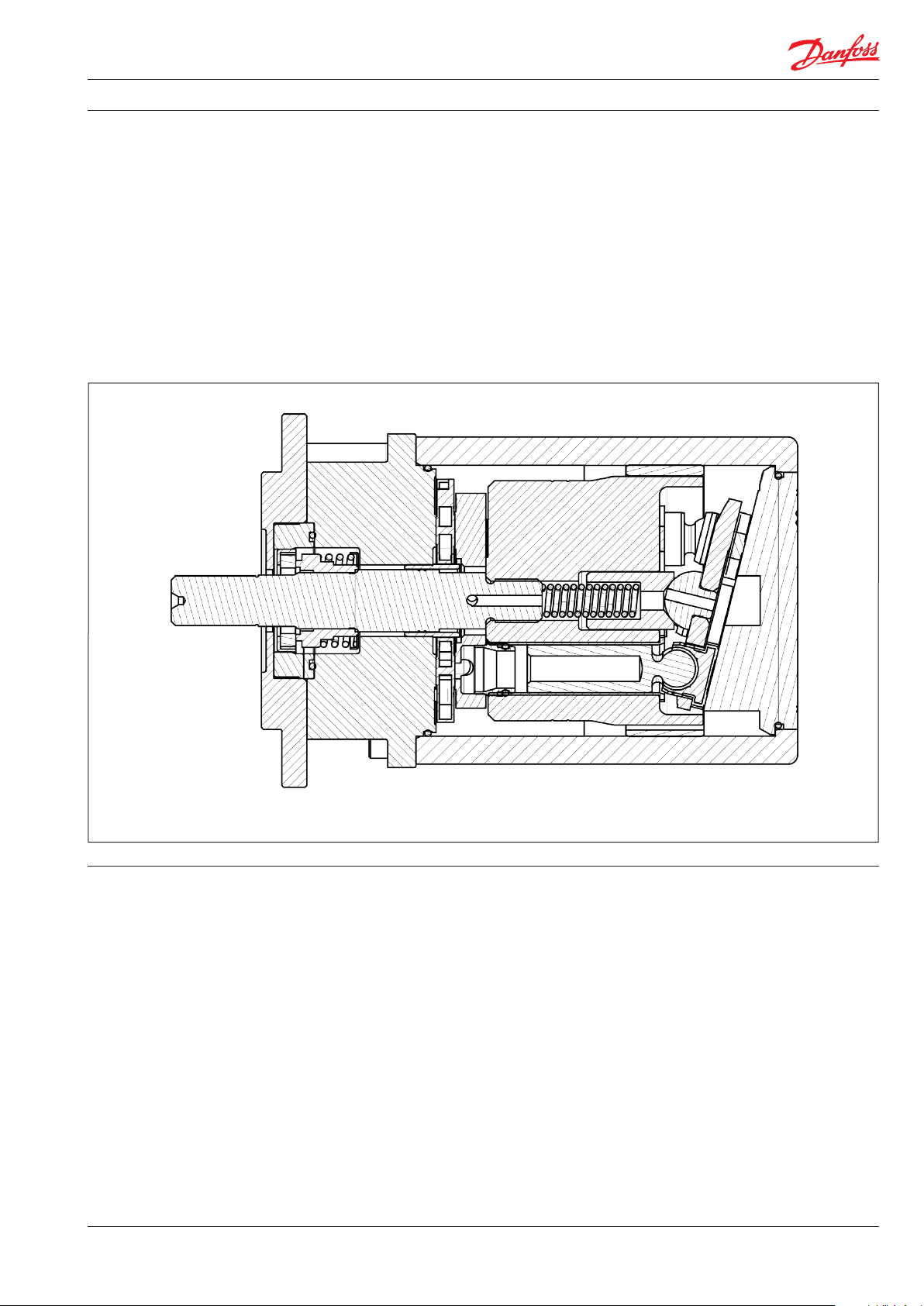
Below a sectional drawing as an example of an
APM motor
2. Benets
• Constant torque over a wide speed range
• Compact design
• Easy to install
• Long life under severe operating conditions
• Few wear parts and low maintenance costs
• No oil lubrication
• Non-corroding materials
• Made for RO applications
AI354846545311en-000101 | 3Danfoss | DCS (im | 2020.09
Page 4
Data sheet | APM 0.8 – 2.9 motors
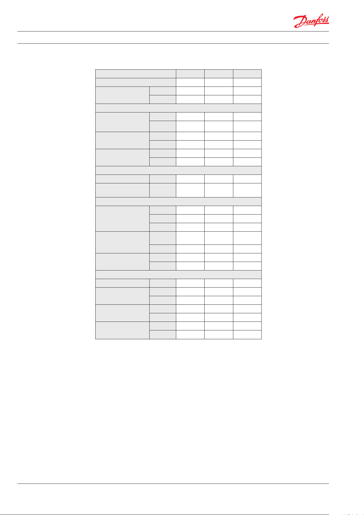
3. Technical data
3.1 APM 0.8 – 1.2
Motor size APM 0.8 APM 1.0 APM 1. 2
Code number APM CCW 180F1000 180F1001 180F1002
Geometric displacement
Pressure
Max. inlet
pressure
continuous
Min. inlet pressure
continuous
Outlet
pressure
Speed
Min. speed rpm 700 700 700
Max. speed
continuous
Typical performance
Max. waterow
Max. power at
max. speed cont. and
max. pressure
Max. torque at max.
pressure
Technical specications
Sound pressurre level dB(A) 74 74 74
Media temperature
Ambient temperature
Weight (dry)
cm³/rev. 4.07 5.08 6.30
in³/re v. 0.25 0.31 0.38
barg 80 80 80
psig 116 0 116 0 1160
barg 10 10 10
psig 145 145 145
barg 0.5 – 5 0.5 – 5 0.5 – 5
psig 7.3 – 72.5 7.3 – 72.5 7.3 – 72.5
rpm 3450 3450 3450
m³/h 0.92 1.12 1.37
l/min 15.3 18.6 22.9
gpm 4.0 4.9 6.1
kW 1.7 2.1 2.6
HP 2.3 2.8 3.5
Nm 4.7 5.8 7. 2
lbf-ft 3.4 4.3 5.3
°C 2 – 50 2 – 50 2 – 50
°F 35.6 – 122 35.6 – 122 35.6 – 122
°C 0 – 50 0– 50 0 – 50
°F 32 – 122 32 – 122 32 – 122
kg 5.2 5.2 5.2
lb 11.5 11. 5 11.5
4 | Danfoss | DCS im) |2020.09
AI354846545311en-000101
Page 5
Data sheet | APM 0.8 – 2.9 motors
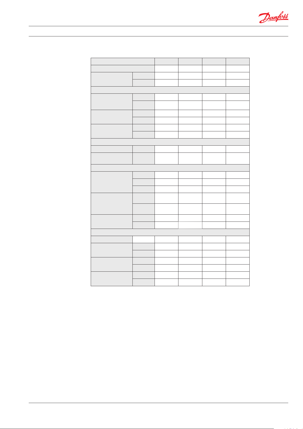
3.2 APM 1.8 – 2.9
Motor size APM 1.8 APM 2.0 APM 2.5 AMP 2.9
Code number APM CCW 18 0F1100 18 0F1101 18 0F1102 180F110 3
Geometric displacement
Pressure
Max. inlet
pressure
continuous
Min. inlet pressure
continuous
Outlet pressure
Speed
Min. speed rpm 700 700 700 700
Max. speed
continuous
Typical performance
Max. waterow
cm³/rev. 9. 31 10.0 12 .5 15. 3
in³/re v. 0.57 0 .61 0.76 0.93
barg 80 80 80 80
psig 116 0 116 0 1160 1160
barg 10 10 10 10
psig 145 145 145 145
barg 0.5 – 5 0.5 – 5 0.5 – 5 0.5 – 5
psig 7.3 – 72.5 7.3 – 72.5 7.3 – 72.5 7.3 – 72.5
rpm 3450 3450 3450 3000
m³/ h 2.03 2.18 2.69 2.83
l/min 33.9 36.4 44.8 47.2
gpm 9.0 9.6 11.8 12 .5
Max. power at
max. speed cont. and
max. pressure
Max. torque at max.
pressure
Technical specications
Sound pressure level dB(A) 77 77 77 81
Media temperature
Ambient temperature
Weight (dry)
kW 3.9 4.2 5.3 5.6
HP 5.2 5.7 7.1 7.6
Nm 10.8 11 .7 14.7 18.0
lbf-ft 8.0 8.6 10.8 13.2
°C 2 – 50 2 – 50 2 – 50 2 – 50
°F 35.6 – 122 35.6 – 122 35.6 – 122 35.6 – 122
°C 0 – 50 0 – 50 0 – 50 0– 50
°F 32 – 122 32 – 122 32 – 122 32 – 122
kg 8.6 8.6 8.6 8.6
lb 19 19 19 19
AI354846545311en-000101 | 5Danfoss | DCS (im | 2020.09
Page 6

Data sheet | APM 0.8 – 2.9 motors
4. Direction of rotation
Connections and direction of rotation appear
from the product label on the motors (see also
the below drawing).
I Inlet
O Outlet
Motor variants
APM motors are optimezed for operation in one
direction: CCW
5. Shaft load
Any axial and/or radial loads on the shaft must
be avoided.
6 | Danfoss | DCS im) |2020.09
AI354846545311en-000101
Page 7

Data sheet | APM 0.8 – 2.9 motors
80
70
60
50
40
30
20
6. Temperature and
corrosion
Fluid temperature:
Min. +2 °C to max. +50 °C
(Min. +35.6 °F to max. +122 °F)
Ambient temperature:
Min. 0 °C to max. +50 °C
(Min. +32 °F to max. +122 °F)
Storage temperature:
Min. -40 °C to + 70 °C - provided that the APM
is drained of uid and stored “plugged”.
Antifreeze protection is required at temperatures
below 0 °C.
º
C
316L
Duplex
Danfoss recommends using Dowcal N from Dow
Chemical Company or Chillsafe mono propylene
glycol from Arco Chemical Company.
The chart below illustrates the corrosive
resistance of dierent types of stainless steel
related to NaCl concentration and temperature.
All critical parts of the APM motors are made of
Duplex and Super Duplex. If the APM motor is
operated above the Duplex line, always ush the
APM with fresh water at operation stop to
minimize the risk of crevice corrosion.
NaCI vs. temperature
Super Duplex
7. Noise level
8. Filtration
100
1000
160 1600
Generally, noise will be reduced if speed is reduced and vice versa. Use exible hoses in order
to minimize vibrations and noise.
Since the APM motor typically is mounted on a
bell housing or frame, the noise level can only be
determined for complete unit (system).
Proper ltration is crucial for the performance
maintenance and warranty.
The water supplied must be ltered: 10 µm absolute, ß10-value > 5000 lter is recommended.
-
10 000
16000
It is therefore very important that the energy
recovery unit is mounted correctly on a frame
with vibration absorber to minimize vibrations
and noise.
The noise level is inuenced by:
• The speed of the pump/motor. High rpm
creates more noise than low rpm
• Rigid mounting of the pump/motor generates more noise than exible mount
• Pipe mounting direct to the pump/motor
increases the noise level compared to a
exible hose
For further information on lters, please contact
Danfoss High Pressure Pumps sales department.
100 000
160000
CI
ppm
NaCI
ppm
AI354846545311en-000101 | 7Danfoss | DCS (im | 2020.09
Page 8

Data sheet | APM 0.8 – 2.9 motors
9. Orientation
The drawing shows preferred acceptable, and
not acceptable orientations of the motor.
Preferred
Not acceptable
10. Installation
8 | Danfoss | DCS im) |2020.09
It is recommended to use exible coupling and
ensure that the gab between the two metal parts
of the coupling is min. 3 mm.
A: Elastic coupling
B: Bell housing
C: Motor shaft
AI354846545311en-000101
Page 9

Data sheet | APM 0.8 – 2.9 motors
11. Preferred system
design
APM is used for energy recovery unit which consists of an APP pump and an APM motor, both
connected to a double shafted electric motor.
Energy recovery is obtained when high-pressure
brine from the membranes is fed to the APM that
converts the energy in the pressurized brine to
mechanical energy to be reused by the electric
motor. As the APM has a xed volumetric displacement, the recovery rate will be xed.
System example
Permeate
Outlet
Pump
Feed
Motor
AI354846545311en-000101 | 9Danfoss | DCS (im | 2020.09
Page 10

Data sheet | APM 0.8 – 2.9 motors
The design of the system must ensure that self
emptying of the water motor during standstill
is avoided. Always place the outlet line
higher than the water motor.
Air in the water will cause cavitation and
damage the water pump and the water motor.
11.1 Membrane system with energy recovery
1
4
APP
5
M
APM
8
Feed
Outlet
10 micron
2
absolut
Filter
6
PS
In order to eleminate the risk of damage and
cavitation, observe the following guidelines:
1.
For easy system bleeding without starting up the system, the APP pump has an
integrated ushing valve (1).
2.
Place an inlet lter (2) in front of the APP
pump (3). Please consult section 8, “Filtration” guidance on how to select the right
lter.
Important:
Thoroughly clean pipes and ush system
prior to start-up — the APP pump and the
APM must be bypassed
3.
Place a monitoring pressure switch (6) set
at min. 1 bar between lter and pump inlet.
The monitoring switch must stop the pump
at pressures lower than 1 bar (14.5 psi). At
3000 rpm — use 2 bar (29 psi) as set point.
4.
Dimension the inlet and outlet lines to
obtain minimum pressure loss (large ow,
minimum pipe length, minimum number of
bends/connections, and ttings with small
pressure losses).
7
9
PI
3
5
9
PI
Brine
55
5.
Always maintain a positive pressure at the
17
Permeate
pump inlet (4) of min. 0.5 bar (7.3 psi) and
max. 5 bar (72.5 psi). At speeds above 3000
rpm the pressure at the inlet of the water
pump must be min. 2 bar (29 psi).
6.
Use exible hoses (5) to minimize vibrations
and noise.
7.
Install a safety valve (7) in order to avoid
system damage as the Danfoss APP pump
creates pressure and ow immediately after
start-up, despite any counter pressure.
8.
Always maintain a pressure at the motor inlet
(8) of min. 10 bar (145 psi) and max. 80 bar
(1160 p si).
9.
As the pressure on the outlet line must not
exceed 5 bar (72.5 psi), do not throttle the
water motor outlet.
10 | Danfoss | DCS im) |2020.09
AI354846545311en-000101
Page 11

Data sheet | APM 0.8 – 2.9 motors
11.2 Membrane system with energy recovery and VFD
1
4
APP
5
M
APM
8
Feed
Outlet
10 micron
2
absolut
Filter
6
PS
In order to eleminate the risk of damage and
cavitation, observe the following guidelines:
1.
For easy system bleeding without starting up the system, athe APP pump has an
integrated ushing valve (1).
2.
Place an inlet lter (2) in front of the APP
pump (3). Please consult section 8, “Filtration” guidance on how to select the right
lter.
Important:
Thoroughly clean pipes and ush system
prior to start-up — the APP pump and the
APM must be bypassed
3.
Place a monitoring pressure switch (6) set
at min. 1 bar between lter and pump inlet.
The monitoring switch must stop the pump
at pressures lower than 1 bar (14.5 psi). At
3000 rpm — use 2 bar (29 psi) as set point.
4.
Dimension the inlet and outlet lines to
obtain minimum pressure loss (large ow,
minimum pipe length, minimum number of
bends/connections, and ttings with small
pressure losses).
7
9
P-18
PT
3
5
9
10
55
Brine
In order to eliminate the risk of damage and
5.
PI
17
Permeate
cavitation, a positive pressure at the pump
inlet (4) is always to be maintained at min.
0.5 bar (7.3 psi) and max. 5 bar (72.5 psi). At
speeds above 3000 rpm the pressure at the
inlet of the water pump must be min. 2 bar
(29 psi)
Use exible hoses (5) to minimize vibrations
6.
and noise.
Always maintain a pressure at the motor inlet
7.
(8) of min. 10 bar (145 psi) and max. 80 bar
(1160 p si).
As the pressure on the outlet line must not
8.
exceed 5 bar (72.5 psi), do not throttle the
water motor outlet.
Using a VFD (10) makes it possible to control
9.
the rotation speed, ramp up and ramp down
of the electric motor. By altering the rotation speed, the permeate production can be
changed to obtain optimum energy recovery.
Install a pressure transmitter (9) to measure
10.
the pressure at the membran inlet. Use the
signal from the pressure transmitter to obtain
an automatic pressure-controlled adjustment
of the VFD and optimum utilization and load
of the membrane.
AI354846545311en-000101 | 11Danfoss | DCS (im | 2020.09
Page 12

Data sheet | APM 0.8 – 2.9 motors
12. Combinations 12.1 Examples of motor / pump combinations
APP pump/AMP motor APP 1.0/APM 0.8 APP 1.5/APM 1.2 APP 1.8/APM 1.2 APP 2.5/APM 2.0 APP 2.5/APM 1.8
1450 rpm
Feed ow m³/h (g pm) 0.50 (2.2) 0.80 (3.5) 0.85 (3.7) 1.25 (5.5) 1.25 (5.5)
Recovery rate % 29 28 32 29 32
Permeate (± 10%) m³/ h (gpm) 0.14 (0.6) 0. 22 (1.0) 0.27 (1.2) 0. 36 (1.6) 0.40 (1.8)
Electric motor (4 pole) 1.1 kW, IEC 90 1.5 kW, IEC 90 1.5 kW, IEC 90 2.2 kW, IEC 100 2.2 kW, IEC 100
2900 rpm
Feed ow m³/h (g pm) 1.05 (4.6) 1.55 (6.8) 1.65 (7.3) 2.55 (11.2) 2.55 (11.2)
Recovery rate % 29 28 32 29 32
Permeate (± 10%) m³/ h (gpm) 0.30 (1.3) 0.43 (1.9) 0.52 (2. 3) 0.74 (3.3) 0.82 (3.6)
Electric motor (2 poles) 2.2 kW, IEC 90 3 kW, IEC 100 3 kW, IEC 100 5.5 kW IEC 132 5.5 kW IEC 132
1 gpm = 3.79 l/min
12. 2 Flow
1 l/min = 0.26 gpm
1 m³/h = 4.40 gpm
1 gpm = 0.23 m³/h
APP 2.5/APM 1.8
APP 1.8/APM 1.2
APP 1.0/APM 0.8
APP 2.5/APM 2.0
APP 1.5/APM 1.2
12 | Danfoss | DCS im) |2020.09
Due to tolerances of both the pumps and the motors, permeate production will vary according to the
gures above.
AI354846545311en-000101
Page 13

Data sheet | APM 0.8 – 2.9 motors
3
3,5
4
4,5
5
50 60 70
kWh/m
3
bar
Energy cons umption vs. Pre ssure
APP1.5/APM1.2
APP1.0/APM0.8
APP2.5/APM2.0
APP1.8/APM1.2
APP2.5/APM1.8
12.3 Energy consumption vs. pressure
A variation of up to 20% may occur depending
on the rpm and the eciencies of the pump and
the motor.
The curves below are calculated using an eciency of the electric motor of 86% and provided
that the pressure at the inlet of the APM motor is
1 bar less than the pressure from the APP pump.
12.4 Power consumption
Motor / pump combination
APP 1.0/
APM 0.8
kWh
APP 1.5/
APM 1.2
kWh
APP 1.8/
APM 1.2
kWh
1 hp hr = 0.75 kWh
1 kWh = 1.34 hp hr
APP 2.5/
APM 2.0
kWh
APP 2.5/
APM 1.8
kWh
Recovery rate (%) 29 28 32 29 32
50 bar (725psi) 1450 rpm 0.6 0.9 0.9 1.4 1.5
50 bar (725 psi) 2900 rpm 1.2 1.7 1.9 2.8 3.0
60 bar (870 psi) 1450 rpm 0.7 1.0 1.2 1.7 1.5
60 bar (870 psi) 2900 rpm 1.5 2.1 2.3 3.4 3.5
70 bar (1015 psi) 1450 rpm 0.8 1.2 1.3 2.0 2.1
70 bat (1015 psi) 2900 rpm 1.7 2.4 2.7 3.8 4.0
The gures in the table above are calculated
using an eciency of the electric motor of 86%
and provided that the pressure at the inlet of the
APM motor is 1 bar less than the pressure from
the APP pump.
AI354846545311en-000101 | 13Danfoss | DCS (im | 2020.09
Page 14

Data sheet | APM 0.8 – 2.9 motors
13. Dimensions
13.1 APM 0.8 – 1.2
14 | Danfoss | DCS im) |2020.09
AI354846545311en-000101
Page 15

Data sheet | APM 0.8 – 2.9 motors
13.2 APM 1.8 – 2.9
Outlet
Outlet
Inlet
AI354846545311en-000101 | 15Danfoss | DCS (im | 2020.09
Page 16

14. Service Warranty
Danfoss APM motors are designed for long
operation, low maintenance and reduced
lifecycle costs.
Provided that the motorp has been running
according to the Danfoss specications, Danfoss
guarantees 8,000 hours service-free operation,
however, max. 18 months from date of
production.
If Danfoss recommendations concerning
system-design are not followed, it will strongly
inuence the life of the APM motors.
Other factors that aect motor performance and
lifetime include:
- Running the motor at speed outside
specications.
- Supplying the motor with water at
temperature higher than recommended.
- Running the motor at inlet pressure outside
specications.
- Running the motor at outlet pressure
outside the specications.
Maintenance
Periodic inspections are required to ensure worn
parts (if any), are replaced in due time. Operational conditions such as water quality should be
taken into consideration when determining the
frequency of the inspections. Danfoss recommends yearly inspections.
It is recommended to order the purposedesigned tool kit.
Motor shutdown:
The APM motors are made of Duplex/Super
Duplex materials with excellent corrosion
properties. It is, however, always recommended
to ush the motor with freshwater when the
system is shut down.
When stopping the motor for more than 1 day
ush the motor with permeate by rotating the
motor for 10 sec. The motor can be ushed with
biocide like the membranes. The biocide must be
compatible with the materials used in our
motors.
Repair assistance
In case of irregular function of the APM motor,
please contact Danfoss High Pressure Pumps.
Danfoss A/S
High Pressure Pumps
DK-6430 Nordborg
Denmark
Danfoss ca n accept no respons ibility for pos sible errors in ca talogues, bro chures and other pr inted material. Da nfoss reserves t he right to alter its p roducts with out notice.
This also a pplies to produc ts already on ord er provided that su ch alterations ca n be made without su bsequential cha nges being nece ssary in speci cations alread y agreed.
All trade marks in this mate rial are proper ty of the respec tive companies . Danfoss and the Dan foss logotyp e are trademark s of Danfoss A/S. Al l rights reserv ed.
© Danfoss | DCS (im) | 2020.09
AI354846545311en-000101 | 16
 Loading...