

Page 1
Data sheet
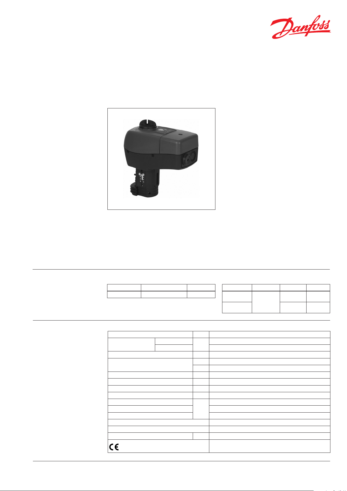
Actuator for modulating control
AME 435 QM
Description
AME
435 QM actuator for modulating control is
used with pressure independent balancing and
control valve type AB-QM from DN 40 to DN 100.
The actuator has some special features:
•
it automatically adapts its stroke to the valve end
positions which reduces commissioning time
• valve ow adjustment feature; ow can be
variably-adjusted from linear to logarithmic or
opposite.
• the advanced design incorporates load
related ‘switch-o’ to ensure that actuators
and valves are not exposed to overload
Main data:
• Nominal voltage (AC or DC):
- 24 V, 50 Hz/60 Hz
• Control input signal:
- 0(4)-20 mA
- 0(2)-10 V
• Force: 400 N
• Stroke: 20 mm
• Speed (selectable):
- 7.5 s/mm
- 15 s/mm
• Max. medium temperature: 120 °C
• Self calibrating
• LED signalling
• External RESET button
• Output signal
• Manual operation
Ordering
Technical data
Actuator
Typ e Supply voltage Code No.
AME 435 QM
Power supply V 24 AC/DC; ±10%
Power consumption
Frequency Hz 50/60
Control input Y
Output signal X V 0-10 (2-10); RL = 650 Ω (maximal load)
Closing force N 400
Max. stroke mm 20
Speed s/mm 7,5 or 15
Max. medium temperature
Ambient temperature 0 … 55
Storage and transport temperature –40 … 70
Protection class II
Grade of enclosure IP 54
Weight kg 0,45
- marking in accordance with standards
24 VAC /DC
running
standby 1,2
08 2H017 1
VA
V 0-10 (2-10); Ri = 95 kΩ
mA 0-20 (4-20); Ri = 500 Ω
°C
Accessories-Adapter
Typ e for valve ’s DN for Actuator Code No.
AB-QM adapter
st
(2
generation)
AB-QM adapter
st
(1
generation)
4,5
120
Low Voltage Directive (LVD) 2006/95/EC: EN 60730-1, EN 60730-2-14
EMC Directive 2004/108/EC: EN 61000-6-2, EN 61000-6-3
40 -100
AME 15 QM 003Z0694
AME 435 QM 065 Z0313
SMT/ SI
VD. CV.S 2.02 © Danfoss 09/2014
1
Page 2
Data sheet Actuator for modulating control AME 435 QM
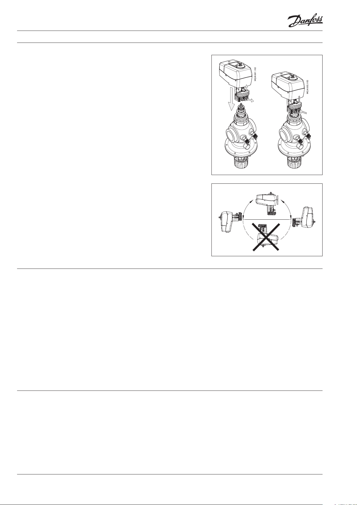
Installation Mechanical
No tool is required to mount actuator on the
valve. Installation of the valve with the actuator
is allowed in horizontal position or upwards.
Installation downwards is not allowed.
The actuator must not be installed in an
explosive atmosphere, at ambient temperature
lower than 0 °C or at ambient temperature
higher than 55 °C. It must not be subject to
steam jets, water jets or dripping liquid as well.
Note:
The actuator may be rotated up to 360° with
respect to the valve stem by loosening the retaining
xture. Once the actuator is placed, retighten the
xture.
Electrical
Electrical connections can be accessed by
removing the actuator cover. Two cable gland
entries without thread (Ø16 and combined Ø16/
Ø20) are prepared for cable glands. From factory
one entry is provided by rubber cable gland and
the other entry is prepared for opening.
③
①
②
⑤
④
Note:
Cable and cable gland used must not compromise
the actuator’s IP rating, and must ensure the
connectors are fully strain relieved.
Rubber cable gland delivered from factory does not
compromise IP rating but it does not provide fully
strain relieve according to LVD directive.
Please observe local rules and regulations as well.
Commissioning Automatic Calibrating feature
Complete the mechanical and electrical
installation, set jumper and DIP-switches, then
perform the necessary checks and tests:
The actuator automatically adapts its stroke to
the valve end positions :
- when power is applied for the rst time or
• Apply power
Note that the actuator will now perform
- afterwards by pressing the STAND BY/RESET
button for 5 seconds
automatic Calibrating function
Testing entire valve stroke length
• Apply the appropriate control signal and
check:
- SW7 setting
The actuator can be driven to the fully-open or
closed positions by connecting SN to terminals
1 or 3.
- the actuator drives the valve over the entire
stroke length
The unit is now fully commissioned.
Disposal
2
The actuator must be dismantled and the
elements sorted into various material groups
before disposal.
VD. CV.S 2. 02 © Danfoss 09/2014
SMT/ SI
Page 3
Data sheet Actuator for modulating control AME 435 QM
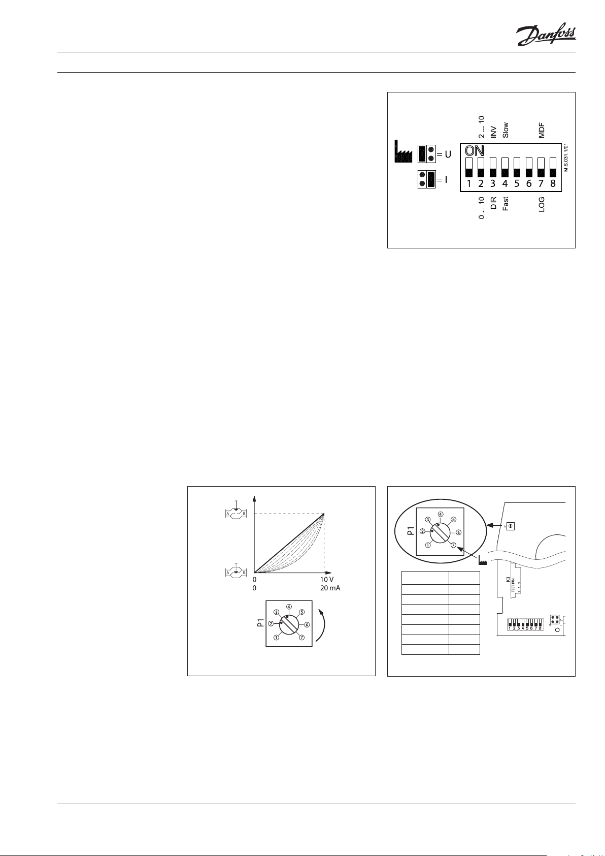
Jumper/DIP switch setting
Jumper
• U/I - Input signal type selector
- U position; voltage input is selected
- I position; current input is selected
Factory setting: jumper is in U position.
DIP switches
Factory setting: all switches are in OFF position.
• SW 1: Not used
• SW 2: Input signal range selector
- OFF position; the input signal is in the range
from 0-10 V (voltage input) or from 0-20 mA
(current input)
- ON position; the input signal is in the range
from 2-10 V (voltage input) or from 4-20 mA
(current input)
• SW 3: Direct or Inverse acting selector
- OFF position; the actuator is in direct acting
mode (stem extracts as voltage increases)
- ON position; the actuator is in inverse acting
mode (stem retracts as voltage increases)
If used with AB-QM valves, SW 3 is recommended
to be in OFF position (factory setting).
• SW 4: Fast/Slow - Speed selector
- OFF position; the actuating speed is 7.5 s/mm
- ON position; the actuating speed is 15 s/mm
• SW 5: Not used
• SW 6: Not used
• SW 7: LOG/MDF - Logarithmic or modied
ow through valve selector
- OFF position; ......... LOG (α=0.2, factory setting)
- ON position; ........... MDF (initial setting:
α=1, linear)
Explanation:
If SW 7 is in OFF position, alpha knob is
not activated. Turning alpha knob will not
inuence α value (α=0.2).
If SW 7 is in ON position, α value can be
manipulated using alpha knob. MDF initial
setting of alpha knob is 1, which means
linear setting. Regarding alpha knob setting
see explanation below.
• SW 8: Not used
SMT/ SI
Alpha knob f ound on PCB in MDF initial se tting (linear, α=1)
Equal-percentage valve-ow adjustment
(SW 7 in position ON)
The actuator has a special valve-ow
adjustment feature called alpha value. Actuator
characteristics can be, by turning the alpha knob
counter clockwise (CCW), variably-adjusted
from α=1 (linear) to α=0.1.
VD. CV.S 2. 02 © Danfoss 09/2014
α-knob position α- value
①
②
③
④
⑤
⑥
⑦
0,084
0,088
0, 111
0,18 0
0,308
1,000
1,000
In order to have optimal control, linear
characteristics of system (valve, actuator, HEX)
is required. This can be assured using the
right α value. Appropriate α value depends on
temperatures of heating/cooling medium and
controlled temperature of heated/cooled medium.
Calculate α value according to the Tech Note
number VNHUA102 (Setting the right α value).
3
Page 4

Data sheet Actuator for modulating control AME 435 QM
Led signalling/
Actuator operating modes
RESET/STAND BY
LED function indicator
The bi-colour (green/red) LED function indicator
is located on the actuator cover. It indicates the
operating modes.
External button
Actuator has external STAND BY/RESET button
which is located next to LED indicator. By
pressing on this button dierent operating
modes are initiated:
• Calibrating mode
Pressing the STAND BY/RESET button for
5sec. causes the actuator to start Calibrating
procedure:
The bi-colour LED ashes green at 1 sec.
intervals during calibration procedure, which
begins by extracting the stem. When the
maximum force is detected (at the end valve
position), the actuator then retracts the
stem, until the maximum force is once again
detected (on the other valve end position).
The actuator will then enter to normal mode
and respond to the control signal.
Flashing green LED:
Calibrating mode
(period is every
second)
Constant green LED:
Positioning mode
Flashing green LED:
Normal mode (period
is every 6 seconds)
Flashing red LED:
STAND BY mode
(period is every two
seconds)
≈
• Positioning mode
The bi-colour LED is green and stays on
during positioning of the actuator according
to the control signal
• Normal mode
When the positioning of the actuator is
nished the LED ashes green every 6
seconds.
• STAND BY mode
Pressing the STAND BY/RESET button switches
the actuator to STAND BY mode. The actuator
keeps its last position in this mode and does
not react to any control signal. This mode
can be used for manual operation during the
commissioning of other equipment, or for
service purposes.
The bi-colour LED ashes red at 2 sec.
intervals.
After pressing the STAND BY/RESET button
again actuator switches to normal mode.
4
VD. CV.S 2. 02 © Danfoss 09/2014
SMT/ SI
Page 5

Data sheet Actuator for modulating control AME 435 QM
Manual override Manual override is done by means of control
knob on actuator housing:
• Disconnect power supply or press STAND BY/
RESET button
• Adjust valve position using the control knob
(observe the rotation direction)
When manual override is not needed:
• Restore power supply or press STAND BY/
RESET button again
Remark:
When the manual override has been used, the
output signal (X) is not correct until the actuator
reaches its end position.
Wiring
24 VAC/DC only
power
supply
down
SP 24 VAC/DC .............. Power supply
SN 0 V ............................. Common
Y 0-10 V ........................ Input signal
(2-10 V)
0-20 mA
(4-20 mA)
X 0-10 V ........................ Output signal
(2-10 V)
1, 3 Override input signal
The actuator can be driven to the fully-open
position by connecting SN to terminal 1 or fullyclosed by connecting SN to terminal 3.
Signal 1 can be connected to thermostat to
prevent freezing and signal 3 can be connected
to thermostat to prevent overheating.
Wiring length
0-50 m 0.75 mm
up
> 50 m 1. 5 mm
Recommended cross-sectional
area of the wiring
2
2
Important: AME 435QM can be used only for
modulating control. For 3-point control use
AMV 435 (082H0162/163). It is recommend to use
modulating control with AB-QM.
SMT/ SI
VD. CV.S 2. 02 © Danfoss 09/2014
5
Page 6

Data sheet Actuator for modulating control AME 435 QM
Actuator - valve
combinations
AME 435 QM + AME 435 QM + AME 435 QM +
AB-QM (DN 40/50) AB-QM (DN 50) AB-QM (DN 65-100)
Dimensions
147
82,5
159, 5
min . 180
6
VD. CV.S 2. 02 © Danfoss 09/2014
SMT/ SI
Page 7

Data sheet Actuator for modulating control AME 435 QM
SMT/ SI
VD. CV.S 2. 02 © Danfoss 09/2014
7
Page 8

Data sheet Actuator for modulating control AME 435 QM
8
VD. CV.S 2. 02
Produce d by Danfoss A/S © 09/2014
 Loading...