

Page 1
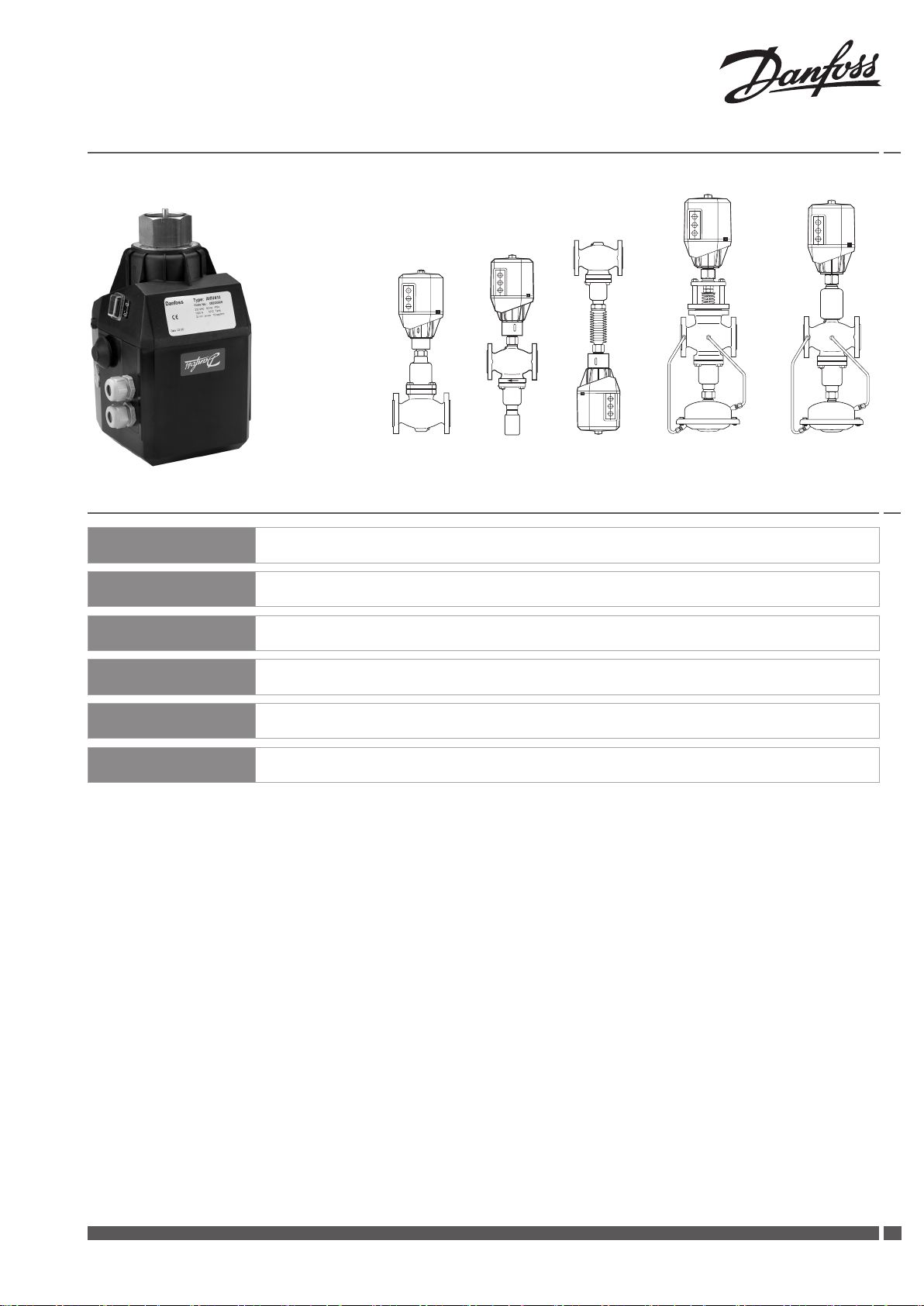
Installation Guide
AME 410, AME 413
VFG 2 VFU 2 VFGS 2 AFQM AFQM 6
VFG 21
VFG 25
ENGLISH
DEUTSCH
FRANCAIS
POLSKI
РУССКИЙ
中文
Electrical Actuator AME 410, 413 www.danfoss.com Page 5
Elektrischer Stellantrieb AME 410, 413 www.iwk.danfoss.de Page 7
Servomoteur électrique AME 410, 413 www.danfoss.fr Page 9
Siłownik elektryczny AME 410, 413 www.danfoss.pl Page 11
Электропривод AME 410, 413 www.danfoss.ru Page 13
电动调节阀驱动器 www.danfoss.com.cn
第15页
Danfoss Heating VI.AA.R4.6Z DEN-SMT/SI
1
Page 2
Installation Guide AME 410, AME 413
❶
❸
DN 15 - 80 < 120 °C
DN 15 - 80 > 120 °C
❹
VFG (DN 15-80)
VFGS 2 (DN 15-80)
AFQM )DN 65, 80
AFQM 6 (DN 40, 50)
AFQM , AFQM 6
AFQM , AFQM 6
VFU 2 (DN 15-80)
❷
VFG 2
VFG 21
VFG 25
15-80 15-65 15-80 15-80 15, 80 40, 50
VFU 2
VFU 2
VFU 2 VFGS 2 AFQM AFQM 6
VFG 2 (21), (25)
VFG 2 (21), (25)
❺
❼
VFGS 2
①
⑦
④
②
⑤
⑧
③
⑥
❻
❾
①
VFG..
VFU 2
VFG 2
VFG 21
VFG 25
VFGS 2
VFU 2
②
DN 15 20 25 32 40 50 65 80
L
B 212 212
B
C 311 311
130
mm
kg 7 9 10 13 17 22 33 41
mm
kg 7 9 10 13 17 22 33 41
250 260 280
95 95
238 238
106 106
337 337
200
230
290 310
240
240
275
123
123
135 135
339
339
374 374
275
AME 413 AME 410
2
DEN-SMT/SI VI.AA.R4.6Z Danfoss Heating
VFG(S) VFU
Page 3
Installation Guide AME 410, AME 413
➑
❿
①
①
②
②
•
21
⓫
①
–
++
+
–
++
+
0(4)-20 mA
0(2)-10 V
①
0(4)-20 mA
0(2)-10 V
0(4)-20 mA
0(2)-10 V
24 VAC
PE
End
switches
②
Input
stroke
Output
controller
Power
supply
Valve closed
(VFU Open)
Valve Open
VFU2 closed
⓬
⓭
①
3 mm
⑤
①
④
②
⑥
② ③
6
5
③ ④
ON
OFF
⑦ ⑧
⑨
VFG 2
VFG 21
VFG 25
AFQM – 12 18
AFQM 6 – 8 12 –
VFU 2 8 8 8 10 10 14 14 2 0
⓯
15 2 0 25 32 4 0 50 65 80
6 6 6 8 8 12 12 18
mm
20 mA
10 V
0 (2,4)
Stroke
0 100 %
Hub
Course
Skok
Danfoss Heating VI.AA.R4.6Z DEN-SMT/SI
33
Page 4
Installation Guide AME 410, AME 413
⓮
⓰
⓱
①
⑤
S2
3
3
ON
OFF
ON
OFF
1
2
ON
OFF
②
0-20 mA
0-10 V
4-20 mA
2-10 V
ON
OFF
④
S2
4
4
ON
7
8
OFF
ON
7
8
OFF
①
0-20 mA
4-20 mA
S2
ON
7
4
4
8
OFF
ON
7
8
OFF
③
①
0-10 V
2-10 V
④
②
①
ON
OFF
⓲
2
1
③
ON
OFF
④
①
1
②
2
③
1
2
②
⑤
⓴
⑤
1
21
②
2
ON
OFF
③
⑥
21
ON
OFF
1
ON
OFF
⓳
①
⑤
ON
OFF
ON
OFF
2
20 mA
10 V
⑦
1
2
VFG .., AFQM 6 VFG .., AFQM 6 VFU 2 VFU 2
2
20 mA
10 V
ON
OFF
2
20 mA
10 V
ON
OFF
2
20 mA
10 V
⑥
ON
OFF
④
1
ON
OFF
ON
OFF
0 (2,4)
4
DEN-SMT/SI VI.AA.R4.6Z Danfoss Heating
Stroke
0 100 %
Hub
Course
Skok
Ход
行程
0 (2,4)
0 100 %
Stroke
Hub
Course
Skok
Ход
行程
0 (2,4)
0 100 %
Stroke
Hub
Course
Skok
Ход
行程
0 (2,4)
0 100 %
Stroke
Hub
Course
Skok
Ход
行程
Page 5
Installation Guide AME 410, AME 413
LANGUAGEENGLISH
Safety Notes
Mounting
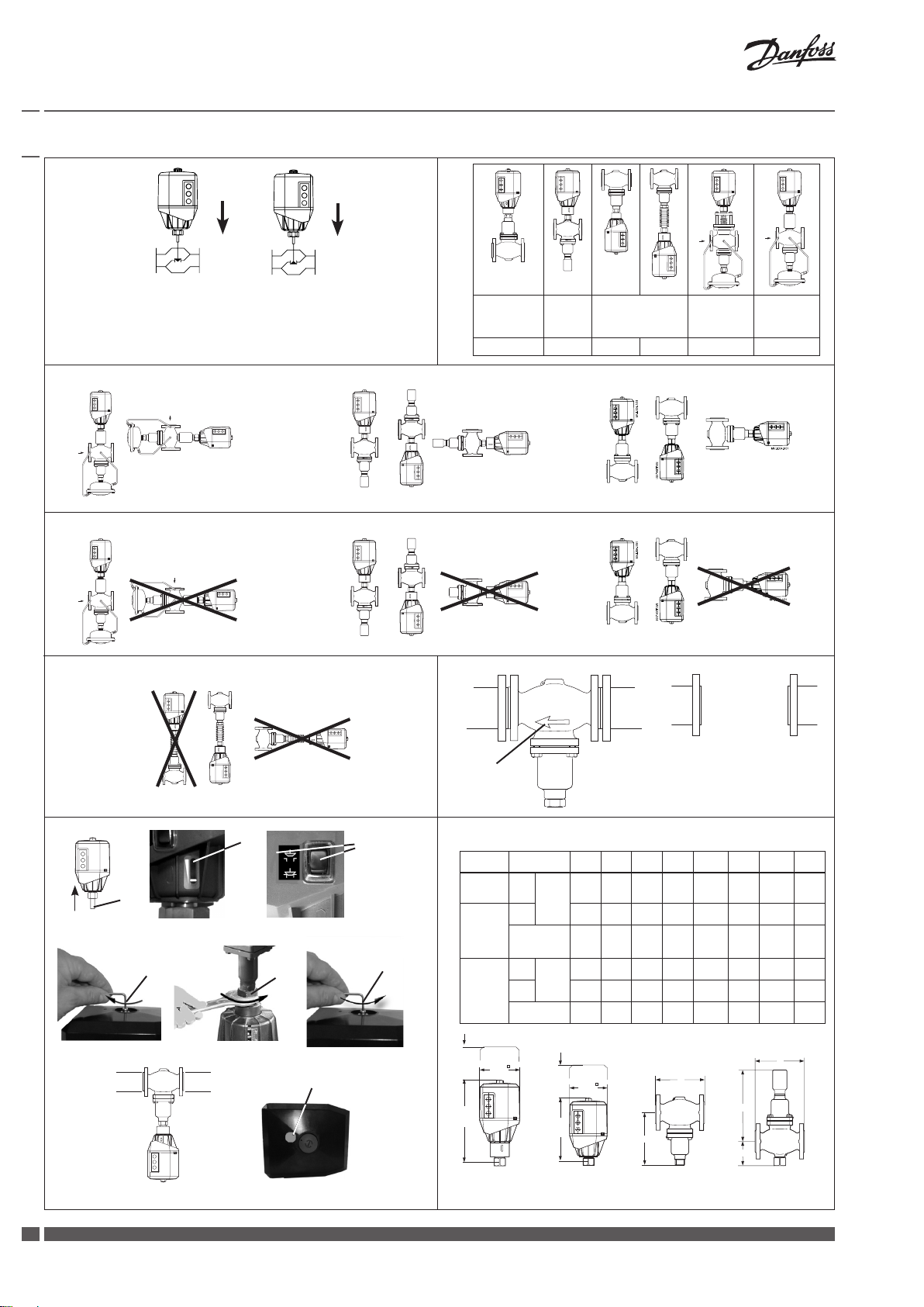
Dimensions, Weights ❾
Prior to assembly and commissioning
to avoid injury of persons and damages
of the devices, it is absolutely necessary
to carefully read and observe these
instructions.
Necessary assembly, start-up, and
maintenance work must be performed
only by qualified, trained and authorized
personnel.
Prior to assembly and maintenance work
on the controller, the system must be:
- depressurized,
- cooled down,
- emptied and
- cleaned.
Please comply with the instructions of the
system manufacturer or system operator.
Do not remove the cover before the power
supply is fully switched off.
Disposal instruction
This product should be
dismantled and its
components sorted, if
possible, in various groups
before recycling or disposal.
Always follow the local disposal
regulations.
Definition of Application
The electrical actuator is used in
connection with the following valves:
VFG 2(21), VFG 25, VFU 2, VFGS 2, AFQM,
AFQM 6.
Fields of application are the temperature
control of water, water-glycol mixtures
and steam for heating, district heating and
cooling systems.
Safety ReturnFunction and
Effective Direction ❶
Safety function and effective direction of
stem:
AME 410
AME 413 valid only for AMV 413.
Permissible Installation Positions
DN 15 - 80 ❸
medium temperatures up to 120 °C.
DN 15 - 80 ❹
medium temperatures > 120 °C.
For valves VFGS 2 ❺ steam.
Valve Installation ❻
• Install strainer in front of valve.
• Rinse system before installing valve.
• Observe flow direction ① on the valve
body.
Flanges ② in the pipeline system must be
in parallel direction, the sealing surfaces
must be clean and undamaged.
• Install valve.
• Tighten screws crosswise in 3 steps up
to the maximum torque.
Actuator and Valve Installation ❼
The actuator must only be mounted with
the stem retracted
Stroke indicator
On delivery the stem is retracted with a
screwed-in mounting screw ④.
If this is not the case, then:
• carry out the electrical connection, see
next section,
• press pushbutton ③ and completely
retract the stem ①.
• Screw in mounting screw ④ up to its
stop.
• Place actuator on the valve and align.
• Tighten union nut ⑤ torque 100 Nm0
•
It is absolutely necessary to unscrew
the mounting screw
actuator is out of function.
• If the actuator is installed in a
downward hanging position ⑦,
remove label ⑧.
①.
② must be in position ②.
⑥, otherwise, the
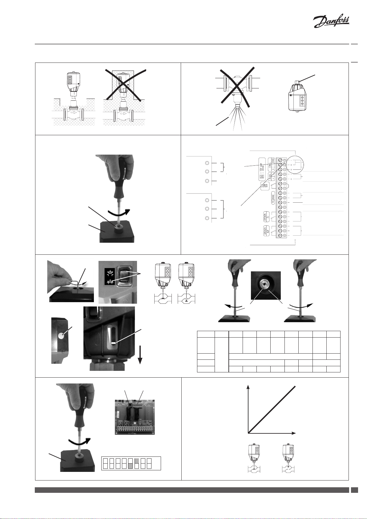
Electrical Connection ❿
HIGH VOLTAGE !
Danger of injury and life in case of
improper handling.
Switch off power supply prior to
connecting lines.
The electrical connection must only be
performed by an expert electrician.
Procedure
• Unscrew cap nut ① and remove
cover ②.
• Connect lines in accordance with
connection diagram ⓫.
• Prior to remounting the cover, carry
out settings at the actuator, see next
section.
Electrical Connection Diagram ⓫
① Connection for:
STB - Safety Temperature Limiter
STW - Safety Temperature Monitor
SDB - Safety Pressure Limiter
Prior to connection, it is absolutely
necessary to remove the jumper
only types AME 413 with safety return
function.
Mechanical Stroke Setting ⓬
The stroke of the electrical actuator must
be adjusted to the valve stroke.
• If not yet done, unscrew the mounting
screw ①.
• Press pushbutton ② until the valve ③
is completely closed (compl. open
VFU 2 ④) and the direction indicator ⑤
stops.
Observe stroke indicator, it must move
to position ⑥.
• Screw in stroke setting screw ⑦ up to
its stop.
• Take valve stroke from table ⑨.
• Unscrew stroke setting screw ⑧ by one
turn per mm valve stroke.
The stroke setting is completed.
Valve Types for AME 410, 413
The electrical actuator AME 41. can be
mounted on the following valves, see
table ❷.
Danfoss Heating VI.AA.R4.6Z DEN-SMT/SI
Insulation ❽
• acceptable ①
• intolerable ②
55
Page 6
Installation Guide AME 410, AME 413
Actuator Electrical Settings ⓭
Prior to commissioning, the settings for the
input und output signals and for the final
positions must be carried out.
Prior to any settings, dismount the
cover ①.
Switch Designations
② Pushbutton S1
③ Switch S2
Switches 5, 6 ④
Switch 5 must be on “OFF”.
Switch 6 has no function.
Setting the Output Signal
The output signal is proportional to the
actuating stroke.
Setting of the switch S2, see ⓮①.
Setting the Input Signal
Connecting the lines to the terminal strip
determines the “current” or “voltage”
input signal, see “Electrical Connection
Diagram”, ⓫.
Setting of 0 or 4 mA, 0 or 2 V, see ⓮②.
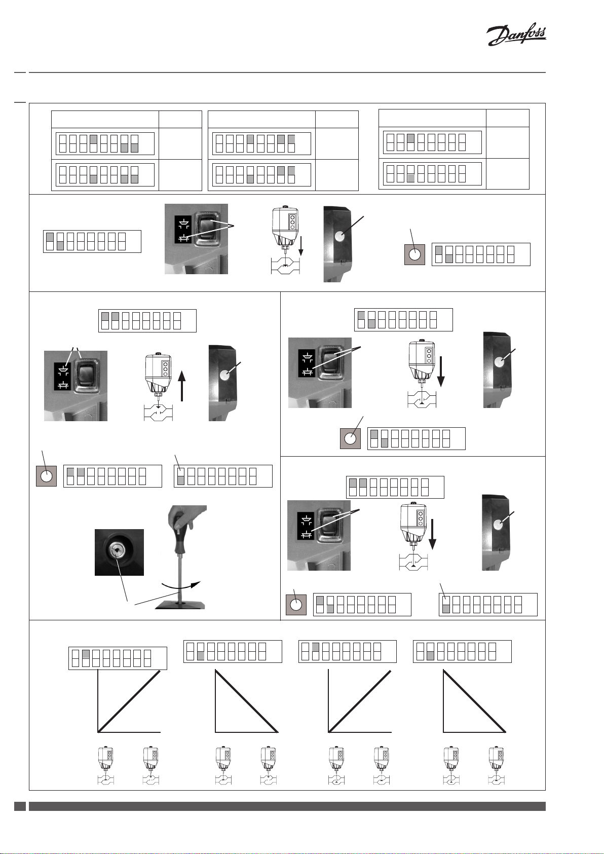
Setting the Final Positions
When the stroke is set (see ⓯), the
final positions “Valve OPEN” and “Valve
CLOSED” must be equalized with current
and voltage values 0(4) - 20 mA, 0(2) - 10 V.
Valves VFG.., AFQM 6
Setting the final position “Valve
CLOSED” ⓰
• Set switches 1 and 2 ①.
• Press pushbutton ② until the valve ③
is completely closed and the direction
indicator ④ stops.
• Press pushbutton ⑤.
The final position “Valve CLOSED” is set.
• Set the assignment of the effective
direction for the input and output
signals, see ⓴
Setting the Final Positions for
valves VFU 2
In contrary to the valves VFG .., AFQM6, the
valve VFU 2 ⓲③ has a reversed closing
direction.
The valve VFU 2 is opened by the safety
return function.
Setting the final position “Valve
OPEN” (VFU 2) ⓲
• Set switches 1 and 2 ①.
• Press pushbutton ② until the valve ③
is completely open and the direction
indicator ④ stops.
• Press pushbutton ⑤.
The final position “Valve OPEN” (VFU 2)
is set.
Setting the final position “Valve
CLOSED” (VFU 2) ⓳
• Set switches 1 and 2 ①
• Press pushbutton ② until the valve ③
is completely closed and the direction
indicator ④ stops.
• Press pushbutton ⑤.
The final position “Valve OPEN” is set.
• Set switch 1 ⑥
The setting of the final positions for the
valves VFU 2 is completed.
• Set the assignment of the effective
direction for the input and output
signals, see ⓴
Assignment of the effective
direction for the input and output
signals
Setting of switch 2 ⓴
Then, remount cap nut and cover.
Setting the final position “Valve
OPEN” ⓱
• Set switches 1 and 2 ①.
• Press pushbutton ② until the valve ③
is completely open and the direction
indicator ④ stops.
• Press pushbutton ⑤.
The final position “Valve OPEN” is set.
• Set switch 1 to standard mode ⑥.
• Unscrew the stroke limiting screw ⑦ by
one turn.
The setting of the final positions for the
valves VFG.., AFQM 6 is completed.
6
DEN-SMT/SI VI.AA.R4.6Z Danfoss Heating
Dismounting of Valve and
Actuator •
Danger
Danger of injury by steam or hot water!
Valve without actuator is open ①, sealing
② is in the actuator.
It is absolutely necessary to depressurize
system prior to dismounting.
Carry out dismounting in reverse order as
mounting.
21
Page 7

Installation Guide AME 410, AME 413
LANGUAGEDEUTSCH
Sicherheitshinweise
Vor dem Einbau und der Inbetriebnahme
ist zur Vermeidung von Personenschäden
und Schäden an den Geräten die
vorliegende Betriebsanleitung sorgfältig
durchzulesen und unbedingt zu beachten.
Einbau-, Inbetriebnahme- und
Wartungsarbeiten dürfen nur durch
geschultes und autorisiertes Fachpersonal
durchgeführt werden.
Vor dem Einbau des Ventils und der
anschließenden Montage des Stellantriebs
und vor Wartungsarbeiten an der
Ventileinheit muss die Anlage:
- drucklos gemacht werden
- abkühlen
- entleert werden
- gereinigt werden.
Die Vorgaben des Anlagenherstellers oder
des Anlagenbetreibers sind zu beachten.
Entfernen Sie die Abdeckung nicht,
bevor die Stromversorgung komplett
ausgeschaltet ist.
Entsorgungshinweise
Vor der Entsorgung ist der
Stellantrieb zu zerlegen. Die
einzelnen Komponenten
sind dann, nach Werkstoffen
getrennt, zu entsorgen.
Entsorgungsbestimmungen sind zu
beachten.
Bestimmungsgemäße
Verwendung
Der elektrische Stellantrieb wird in
Verbindung mit folgenden Ventilen
eingesetzt: VFG 2(21), VFG 25, VFU 2, VFGS
2, AFQM, AFQM 6
Einsatzgebiete sind Temperaturregelung
von Wasser, Wasser-Glykolgemischen und
Dampf für Heizungs-, Fernheizungs- und
Kühlungsanlagen.
Sicherheitsfunktion und
Wirkrichtung ❶
Sicherheitsfunktion und Wirkrichtung der
Antriebsstange.
Ventiltypen für AME 410, 413
Der elektrische Stellantrieb AME 41. kann
auf folgende Ventile montiert werden,
siehe Tabelle ❷.
Montage
Zulässige Einbau-lagen
DN 15 - 80 ❸
Mediumstemperaturen bis 120 °C
DN 15 - 80 ➍
Mediumstemperaturen größer 120 °C
Für Ventile VFGS 2 ❺
Dampf
Einbau Ventil ❻
• Schmutzfänger vor dem Ventil
einbauen
• Anlage vor dem Einbau des Ventils
spülen
• Durchflussrichtung ① auf dem
Ventilgehäuse beachten
Flansche ② in der Rohr-leitung müssen
parallel, Dichtflächen sauber und ohne
Beschädigung sein..
• Ventil einbauen
• Schrauben über Kreuz in 3 Stufen bis
zum max. Drehmoment anziehen.
Montage Stellantrieb und Ventil ❼
Der Stellantrieb darf nur mit eingefahrener
Schubstange ① montiert werden.
Hubanzeige ② muss in Position ② stehen.
Bei Auslieferung ist die Schubstange
mittels eingeschraubter Montagechraube
④ eingefahren.
Ist das nicht der Fall, dann :
• elektrischen Anschluss durchführen,
siehe nächsten Abschnitt
• Taster ③ drücken und Schubstange ①
vollständig einfahren
• Montageschraube ④ bis zum Anschlag
einschrauben.
• Stellantrieb am Ventil ansetzen und
ausrichten
• Überwurfmutter ⑤ anziehen
Anzugsmoment 100 Nm
•
Montageschraube ⑥ unbedingt
herausschrauben, sonst ist der
Stellantrieb außer Funktion.
• Bei hängendem Einbau des
Stellantriebs ⑦ Aufkleber ⑧ entfernen.
Isolierung ➑
• zulässig ①
• unzulässig ②
Abmessungen, Gewichte ❾
Elektrischer Anschluss ❿
Gefahr durch stromschlag!
Bei unsachgemäßer Handhabung besteht
Lebens- oder Verletzungsgefahr.
Vor dem Anschluss der Leitungen
unbedingt Spannungsversorgung
abschalten.
Durchführung des elektrischen
Anschlusses nur durch Elektrofachkraft.
Vorgehensweise
• Hutmutter ① abschrauben und Haube
② abnehmen
• Leitungen nach dem Anschlussplan
anschließen ⓫
• Vor Montage der Haube, Einstellungen
am Stellantrieb durchführen, siehe
nächsten Abschnitt
Elektrischer Anschlussplan ⓫
① Anschluss für:
STB - Sicherheits-temperaturbegrenzer
STW - Sicherheits-temperaturwächter
SDB- Sicherheits-druckbegrenzer
Bei Anschluss unbedingt Brücke
entfernen nur Typen AME 413 mit
Sicherheitsfunktion.
Input cont roller Eingang re gler
Output s troke Ausgang Hu b
Power supp ly Spannun gs versorgung
Valve close d (VFU2 Open) Ventil zu (VFU2 Auf )
End swit sches Endschal ter
Valve Open ( VFU2 closed) Ventil Auf (VFU2 zu)
Danfoss Heating VI.AA.R4.6Z DEN-SMT/SI
77
Page 8

Installation Guide AME 410, AME 413
Mechanische Hubeinstellung ⓬
Der Hub des elektrischen Stellantriebs
muss dem Ventilhub angepasst werden.
• Falls noch nicht durchgeführt, die
Montageschraube ① herausschrauben.
• Taster ② drücken bis das Ventil ③ ganz
geschlossen (VFU 2 ④ ganz geöffnet)
ist und die Lauf-richtungsanzeige ⑤
zum Stillstand kommt.
Hubanzeige beachten, sie muss bis
Position ⑥ fahren.
• Hubeinstellschraube ⑦ bis zum
Anschlag eindrehen.
• Ventilhub aus Tabelle ⑨ entnehmen
• Hubeinstellschraube ⑧ pro mm
Ventilhub um eine Umdrehung
herausdrehen
Die Hubeinstellung ist abgeschlossen
Elektrische Einstellungen am
Stellantrieb ⓭
Vor der Inbetriebnahme müssen die
Einstellungen für die Ein-, Ausgangssignale
und für die Endlagen durchgeführt
werden.
Vor den Einstellungen die Haube ①
demontieren.
Ventile VFG.., AFQM 6
Endlage “ Ventil ZU” einstellen
• Schalter 1 und 2 einstellen ①.
• Taster ② drücken bis das Ventil ③
ganz geschlossen ist und die Laufrichtungsanzeige ④ zum Stillstand
kommt
• Taster ⑤ drücken
Endlage “Ventil
Endlage “Ventil AUF” einstellen ⓱
• Schalter 1 und 2 einstellen Á
• Taster  drücken bis das Ventil
Ă ganz geöffnet ist und die.
Laufrichtungsanzeige Ä zum Stillstand
kommt
• Taster Ĺ drücken
Endlage “Ventil AUF” ist eingestellt
• Schalter 1 auf Standardeinstellung
stellen Ć
• Hubbegrenzungs-schraube Ŕ um eine
Umdrehung herausdrehen
Einstellung der Endlagen für Ventile
VFG.., AFQM 6 ist abgeschlossen
• Zuordnung der Wirkrichtung zum Ein-,
Ausgangssignal einstellen, siehe ⓴
Einstellung der Endlagen für Ventile
VFU 2 ist abgeschlossen
• Zuordnung der Wirkrichtung zum
Ein-, Ausgangssignal einstellen, siehe ⓴
Zuordnung der Wirkrichtung zum
Ein-, Ausgangssignal
Einstellung Schalter 2 ⓴
Anschließend Hutmutter und Haube
montieren
Demontage •
Gefahr
Verletzungsgefahr durch Dampf oder
Heißwasser
Ventil ist ohne Antrieb offen ①,
Abdichtung ② befindet sich im Antrieb.
Vor Demontage Anlage unbedingt
drucklos machen.
Demontage in umgekehr-ter Reihenfolge
wie die Montage durchführen.
21
Schalterbezeichnungen
② Taster S1
③ Schalter S2
Schalter 5, 6 ④
Schalter 5 muss auf “OFF” stehen.
Schalter 6 hat keine Funktion.
Einstellung Ausgangssignal
Das Ausgangsignal ist proportional zum
Stellhub.
Einstellung des Schalters S2 siehe ⓮①.
Einstellung Eingangssignal
Durch den Anschluss an der Klemmleiste
wird das Eingangssignal “Strom” oder
“Spannung” festgelegt, siehe “Elektrischer
Anschlussplan” ⓫
Einstellung von 0 oder 4 mA, 0 oder 2 V
siehe ⓮②.
Einstellung der Endlagen
Nach Durchführung der Hubeinstellung
(siehe ⓯) müssen die Endlagen “Ventil
AUF” und “Ventil ZU” noch mit den Strom-,
Spannungswerten 0(4) - 20 mA, 0(2) - 10 V
abgeglichen werden.
Einstellung der Endlagen Ventile
VFU 2
Das Ventil VFU 2 ⓲③ hat gegenüber den
Ventilen VFG.., AFQM 6 eine umgekehrte
Schließrichtung.
Das Ventil VFU 2 wird durch die
Sicherheitsfunktion geöffnet.
Endlage “ Ventil AUF” (VFU 2)
einstellen ⓲
• Schalter 1 und 2 einstellen ①
• Taster ② drücken bis das Ventil
③ ganz geöffnet ist und die Laufrichtungsanzeige ④ zum Stillstand
kommt
• Taster ⑤ drücken
Endlage “Ventil AUF” (VFU 2) ist
eingestellt
Endlage “ Ventil ZU” (VFU 2)
einstellen ⓳
• Schalter 1 und 2 einstellen ①
• Taster ② drücken bis das Ventil ③
ganz geschlossen ist und die Laufrichtungsanzeige ④ zum Stillstand
kommt
• Taster ⑤ drücken
Endlage “Ventil AUF” ist eingestellt
• Schalter 1 einstellen ⑥
8
DEN-SMT/SI VI.AA.R4.6Z Danfoss Heating
Page 9

Installation Guide AME 410, AME 413
LANGUAGEFRANCAIS
Sécurité
Pour éviter des dommages physiques et
matériels, il est absolument nécessaire
de lire attentivement et de respecter ces
instructions avant le montage et la mise en
service.
Le travail d’assemblage, de démarrage
et de maintenance nécessaire doit être
effectué uniquement par un personnel
qualifié, formé et autorisé.
Avant le travail d'assemblage et de
maintenance du contrôleur, le système
doit être:
- dépressurisé
- refroidi
- vidé
- nettoyé
Suivre les instructions du fabricant du
système ou de son service.
Indications de mise au rebus
Ce produit peut être
démonté et tous ses
composants classés si
possible en différentes
catégories en vue de leur
recyclage ou destruction
Dans tous les cas , suivre la législation
locale de mise au rebus.
Conditions d’utilisation
Le servomoteur électrique est utilisé en
combinaison avec les vannes suivantes:
VFG 2(21), VFG 25, VFU 2, VFGS2, AFQM (6)
Domaines d’application : régulation de la
température de l’eau, de l’eau glycolée et
de la vapeur pour chauffage, chauffage
urbain et installations de réfrigération.
Fonction de secours et sens de
fonctionnement ❶
Fonction de secours et sens de
fonctionnement de la tige
Types de vannes pour
AME 410, 413
Le moteur électrique AME 41. peut être
monté sur les vannes suivantes, voir
tableau ❷
Montage
Orientations de montage autorisées
DN 15 - 80 ❸
Température du fluide jusqu’à 120°C :
DN 15 - 80 ➍
Température du fluide supérieure à
120°C :
Pour vannes VFGS2 ❺
Vapeur
Montage vanne
• Monter le filtre devant la vanne
• Rincer l’installation avant le montage de
la vanne
• Respecter le sens d’écoulement ①
indiqué sur le corps de la vanne
Les brides ② dans la tuyauterie doivent
être parallèles, les surfaces d’étanchéité
propres et sans dommages.
• Monter la vanne
• Serrer les vis en 3 étapes en croix,
jusqu’au couple de rotation max.
Montage moteur et vanne ❼
Uniquement monter le moteur avec la
tige ① rétractée.
L’indication de course ② doit être en
position ②
Lors de la livraison, la tige est rétractée
à l’aide de la vis de montage ④ qui est
vissée.
Si cela n’est pas les cas, alors :
• Procéder au branchement électrique,
voir prochain paragraphe
• Presser la touche ③ et rétracter
totalement la tige ①
• Visser la vis de montage ④ jusqu’en
butée.
• Positionner le moteur sur la vanne et
procéder ŕ l’alignement
• Serrer l’écrou prisonnier ⑤ , facteur de
serrage 100 Nm
•
Dévisser impérativement la vis de
montage ⑥ , sinon le moteur est hors
fonction.
• Lors d’un montage du moteur ⑦ vers le
bas, retirer l’autocollant ⑧.
Isolation
① Autorisé
② Non autorisé
Dimensions, poids ❾
Branchement électrique ❿
Danger d’électrocution
Lors d’une manipulation non appropriée,
danger de mort ou risques de blessures.
Avant le branchement des câbles,
impérativement couper l’alimentation.
Le branchement doit être effectué
uniquement par du personnel qualifié.
Procédure:
• Dévisser l’écrou du capot ① et retirer le
capot ②
• Raccorder les câbles selon le schéma de
branchement, voir ⓫
• Avant de remettre le capot, effectuer les
réglages sur le moteur, voir paragraphe
suivant
Schéma de branchement
électrique ⓫
① Branchement pour:
STB – Limiteur de température de sécurité
STW – Contrôleur de température de
sécurité
SDB – Limiteur de pression de sécurité
Lors du branchement, impérativement
retirer le pont Uniquement types
AME 413 avec fonction de secours.
Input cont roller Entrée régulateu r
Output s troke Sorti e Course
Power supp ly Aliment ation
Valve close d (VFU2 Open) Vanne ferm ée (VFU2 ouvert e)
End swit sches Contact s fin de course
Valve Open ( VFU2 closed) Vanne ouver te (VFU2 fermé e)
Réglage mécanique de la
course ⓬
La course du moteur doit être adaptée à la
course de la vanne.
• Si cela n’est pas fait, dévisser la vis de
montage ①.
Danfoss Heating VI.AA.R4.6Z DEN-SMT/SI
99
Page 10

Installation Guide AME 410, AME 413
• Presser la touche ② jusqu’à ce
que la vanne ③ soit totalement
fermée (VFU 2 ④ totalement
ouverte), et l’indicateur de sens de
fonctionnement ⑤ soit arrêté.
Observer l’indication de course, elle
doit aller jusqu’en position ⑥.
• Serrer la vis de réglage de course ⑦
jusqu’en butée
• Relever la course de la vanne dans le
tableau ⑨
• Dévisser la vis de limitation de
course ⑧ d’un tour par mm de course
de vanne
Le réglage de la course est terminé
Réglages électriques sur le
moteur ⓭
Avant la mise en route, procéder aux
réglages pour les signaux d’entrée et de
sortie, et les positions fins course.
Avant les réglages, démonter le capot ①.
Désignation des commutateurs
② Touche S1
③ Interrupteur S2
Interrupteurs 5,6
L’interrupteur 5 doit être sur «OFF».
L’interrupteur 6 n’a pas de fonction.
Vannes VFG..., AFQM6
Régler la position fin de course
«vanne fermée» ⓰
• Régler les interrupteurs 1 et 2 ①.
• Presser la touche ② jusqu’ŕ ce
que la vanne ③ soit totalement
fermée et l’indicateur de sens de
fonctionnement ④ soit arręté
• Presser la touche ⑤
La position fin de course «vanne
fermée» est réglée
Régler la position fin de course
«vanne ouverte» ⓱
• Régler les interrupteurs 1 et 2 ①
• Presser la touche ② jusqu’à ce
que la vanne ③ soit totalement
ouverte et l’indicateur de sens de
fonctionnement ④ soit arrêté
• Presser la touche ⑤
La position fin de course «vanne
ouverte» est réglée
• Positionner l’interrupteur 1 sur réglage
standard ⑥
• Hubbegrenzungs-schraube ⑦ d’un tour
Le réglage des positions fins de course
pour vanne VFG..., AFQM 6 est terminé
• Régler l’affectation du sens de
fonctionnement au signal d’entrée/
sortie, voir page, ⓴
Régler la position fin de course
«vanne fermée» (VFU2) ⓳
• Régler les interrupteurs 1 et 2 ①
• Presser la touche ② jusqu’à ce
que la vanne ③ soit totalement
fermée et l’indicateur de sens de
fonctionnement ④ soit arrêté
• Presser la touche ⑤
La position fin de course «vanne
fermée» est réglée
• Régler l’interrupteur 1 ⑥
Le réglage des positions fins de course
pour vannes VFU2 est terminé
• Régler l’affectation du sens de
fonctionnement au signal d’entrée/
sortie, voir ⓴
Affectation du sens de
fonctionnement au signal
d’entrée/sortie
Réglage de l’interrupteur 2 voir cidessous ⓴
Ensuite monter le capot et l’écrou du capot
Démontage •
Danger
Danger of injury by steam or hot water!
21
Réglage du signal de sortie
Le signal de sortie est proportionnel au
réglage de la course.
Réglage de l’interrupteur S2 ⓮①.
Réglage du signal d’entrée
Le choix de l’entrée «courant» ou
«tension» se fait par le branchement sur
le bornier, voir «schéma de branchement
électrique» ⓫
Réglage de 0 ou 4 mA, 0 ou 2 V, voir ⓮②.
Réglage des positions fins de
course
Après le réglage de la course ⓯, les
positions fins de course «vanne ouverte» et
«vanne fermée» doivent être alignées avec
les valeurs courant et tension 0(4)-20 mA
et 0(2)-10V.
Régler les positions fins de
course pour vannes VFU2
La vanne VFU 2 ⓲③ a un sens de
fermeture contraire par rapport aux
vannes VFG..., AFQM 6
La vanne VFU 2 est ouverte par la fonction
de secours.
Régler la position fin de course
“vanne ouverte” (VFU2) ⓲
• Régler les interrupteurs 1 et 2 ①
• Presser la touche ② jusqu’à ce
que la vanne ③ soit totalement
ouverte et l’indicateur de sens de
fonctionnement ④ soit arrêté
• Presser la touche ⑤
La position fin de course «vanne
ouverte» (VFU2) est réglée
La vanne n’est pas étanche sans moteur ①,
le cône d’étanchéité ② se trouve dans
l’écrou de fixation du moteur.
Impérativement mettre l’installation hors
pression avant tout démontage.
Pour le démontage suivre la procédure de
montage dans le sens inverse.
10
DEN-SMT/SI VI.AA.R4.6Z Danfoss Heating
Page 11

Installation Guide AME 410, AME 413
LANGUAGEPOLSKI
Warunki bezpieczeństwa
W celu uniknięcia zranienia osób
i uszkodzenia urządzeń należy
bezwzględnie przed montażem i
uruchomieniem zaworu zapoznać się
dokładnie z niniejszą instrukcją.
Czynności związane z montażem,
uruchomieniem i obsługą mogą
być dokonywane wyłącznie przez
osoby uprawnione i odpowiednio
wykwalifikowane.
Przed montażem i obsługą konserwacyjną
regulatora należy:
- zrzucić ciśnienie,
- ostudzić urządzenie
- opróżnić układ,
- oczyścić
Prosimy stosować się do instrukcji
producenta lub operatora układu.
Instructiuni de dispensare
Ten produkt powinien być
rozebrany a jego
komponenty
posegregowane, jeśli to
możliwe, na różne grupy
przed poddaniem recyklingowi lub
utylizacji.
Zawsze stosuj siê do miejscowych
przepisów w zakresie usuwania
odpadów.
Zakres zastosowań
Siłownik elektryczny stosowany jest w
połączeniu z następującymi zaworami:
VFG 2(21), VFG 25, VFU 2, VFGS 2, AFQM,
AFQM 6.
Znajdują zastosowanie w regulacji
temperatury wody, roztworu woda-glikol
i pary wodnej w układach grzewczych,
instalacjach sieci cieplnych i chłodzenia.
Safety Function and Effective
Direction ❶
Funkcja bezpieczeństwa i kierunek
działania trzpienia.
Typy zaworów do AME 410, 413
Siłownik elektryczny typu AME 41. może
współpracować z zaworami regulacyjnymi,
zgodnie z Tabelą ❷
Montaż
Dopuszczalne pozycje montażu
DN 15 –80 ❸
temperatura czynnika do 120 °C
DN 15 – 80 ❹
temperatura czynnika powyżej 120 °C;
Dla zaworów VFGS 2 ❺
Czynnik para wodna
Montaż zaworu ❻
• Zamontować filtr przed zaworem.
• Przed zamontowaniem zaworu
przepłukać instalację.
• Zwrócić uwagę na wskaźnik kierunku
przepływu na korpusie zaworu ①.
Kołnierze ②‚ na rurociągu muszą być
wzajemnie równoległe, a powierzchnie
pod uszczelki czyste i bez uszkodzeń.
• Zamontować zawór.
• Dokręcać przeciwległe nakrętki w 3
krokach do osiągnięcia maksymalnego
momentu.
Montaż siłownika i zaworu ❼
Aby siłownik mógł być zamontowany musi
mieć cofniêty trzpień ①.
Wskaźnik położenia ② musi być w pozycji
③.
W przypadku dostawy trzpień jest cofnięty
i zaplombowany śrubą montażową ④.
W przeciwnym wypadku:
• wykonać połączenie elektryczne, patrz
następny rozdział
• naciśnij przycisk ③ do całkowitego
cofnięcia trzpienia ①
• wkręcić śrubę montażową aż do
zatrzymania ④.
• Umieścić siłownik na zaworze
• Dokręcić nakrętkę łączącą ⑤. Moment
35 Nm, klucz 36 mm
•
Należy koniecznie wykrêcić śrubê
montażową ⑥ w innym przypadku
siłownik nie bêdzie działał.
• Kiedy napęd jest skierowany do dołu ⑦
usunąć nalepkę ⑧.
Izolacja ❽
① do przyjęcia
② nie do przyjęcia
Rozmiar, Waga ❾
Podłączenie elektryczne ❿
WYSOKIE NAPIÊCIE !
Ryzyko obrażeń i zagrożenie życia w
przypadku nieprawidłowej obsługi.
Przed wykonaniem podłączeń
elektrycznych należy bezwzględnie
wyłączyć zasilanie.
Podłączenia elektryczne mogą być
wykonane wyłącznie przez uprawnionego
elektryka.
Tryb postępowania
• Odkręcić śrubę ① i usunąć obudowę ②.
• Podłączyć przewody zgodnie ze
schematem podłączeń elektrycznych patrz ⓫.
• Przed założeniem obudowy wykonać
wszystkie nastawy siłownika - patrz
następny rozdział.
Schemat podłączeń
elektrycznych ⓫
① Zaciski do:
STB – Ogranicznik temperatury
bezpieczeństwa
STW – Strażnik temperatury
bezpieczeństwa
SDB – Ogranicznik ciśnienia
bezpieczeństwa
Przed połączeniem należy koniecznie
usunąć mostek.
dot. wyłącznie typów AME 413 z funkcją
sprêżyny powrotnej.
Input cont roller Wejscie sterujace
Output s troke Wyjscie s ygnalu polozen ia
Power supp ly Napięci e zasilania
Valve close d (VFU2 Open) Zawór za mknięty (VFU 2
otwar ty)
End swit sches Przełą czniki krań cowe
Valve Open ( VFU2 closed) Zawór ot warty (VFU2
zamkni ęty)
Danfoss Heating VI.AA.R4.6Z DEN-SMT/SI
1111
Page 12

Installation Guide AME 410, AME 413
Nastawy skoku
mechanicznego ⓬
Skok siłownika elektrycznego musi być
przystosowany do skoku zaworu.
• Jeżeli nie jest to jeszcze zrobione,
odkręcić śrubę montażową ①.
• Wcisnąć przycisk ‚ aż do całkowitego
zamknięcia zaworu ② (VFU 2 ④
całkowitego otwarcia) i do zatrzymania
wskaźnika poziomu ⑤.
Obserwować wskaźnik poziomu, musi
osiągnąć pozycję ⑥.
• Dokręcić śrubę nastawy skoku ⑦, aż do
jej zatrzymania.
• Odczytać skok zaworu z poniższej
tabeli ⑨
• Odkręcić śrubę nastawy skoku ⑧ jeden
obrót na 1 mm skoku zaworu.
Nastawa skoku została zakończona.
Nastawy elektryczne
siłownika ⓭
Przed oddaniem do eksploatacji muszą
być przeprowadzone nastawy sygnałów
wyjściowych i wejściowych jak również
pozycji krańcowych.
Przed dokonaniem nastaw zdjąć
pokrywę ①.
Oznaczenie wyłączników
① przycisk S1
② przełącznik S2
Przełączniki 5, 6 ④
Przełącznik 5 musi być w pozycji „OFF”.
Przełącznik 6 jest niewykorzystany.
Nastawa sygnału wyjściowego
Sygnał wyjściowy jest proporcjonalny do
ruchu trzpienia.
Nastawy przełączników S2 ⓮①
Nastawa sygnału wejściowego
Podłączyć przewody do listwy zaciskowej
określając „prąd” lub „napięcie”
sygnału wejściowego patrz „Schemat
elektryczny” ⓫.
Ustawienie 0 lub 4mA, 0 lub 2V, patrz ⓮②.
Nastawa pozycji krańcowych
Kiedy skok jest ustawiony (patrz ⓯),
należy zrównać pozycje krańcowe „Zawór
otwarty” i „Zawór zamknięty” z wartością
prądu i napięcia 0 (4) – 20 mA, 0(2) – 10V.
Zawory VFG..,, AFQM
Ustawienie pozycji krańcowej
“Zawór zamknięty” ⓰
• Ustaw przełącznik 1i 2 ①
• Naciskać przycisk ② do całkowitego
zamknięcia zaworu ③ i zatrzymania
wskaźnika poziomu ④
• Nacisnąć przycisk ⑤
Pozycja krańcowa „Zawór zamknięty”
została nastawiona.
Ustawienie pozycji krańcowej
“Zawór otwarty” ⓱
• Ustaw przełącznik 1i 2 ①
• Naciskać przycisk ② do całkowitego
otwarcia zaworu ③ i zatrzymania
wskaźnika poziomu ④
• Nacisnąć przycisk ⑤
Pozycja krańcowa „Zawór otwarty”
została nastawiona.
• Nastawić przełącznik 1 na tryb
standardowy ⑥.
• Odkręcić śrubę nastawy skoku ⑦ jeden
obrót.
Nastawa pozycji krańcowych dla
zaworów VIM2, VIS2, AIQM została
zakończona.
• Ustawić przypisanie kierunku sygnałom
wejściowemu i wyjściowemu patrz ⓴
Nastawa pozycji krańcowych dla
zaworów VFU 2
W przeciwieństwie do zaworów VFG..,
AFQM 6 zawór VFU 2 ⓲③ ma odwrotny
kierunek zamykania.
Zawór VFU2 jest otwierany przez funkcję
bezpieczeństwa sprężyny powrotnej.
Ustawienie pozycji krańcowej
“Zawór otwarty” (VIU 2) ⓲
• Ustaw przełącznik 1 i 2 ①
• Naciskać przycisk ② do całkowitego
otwarcia zaworu ③ i zatrzymania
wskaźnika poziomu ④
• Nacisnąć przycisk ⑤
Pozycja krańcowa „Zawór otwarty”
(VFU2) została nastawiona.
Ustawienie pozycji krańcowej
“Zawór zamknięty” (VFU 2) ⓳
• Ustaw przełącznik 1 i 2 ①
• Naciskać przycisk ② do całkowitego
zamknięcia zaworu ③ i zatrzymania
wskaźnika poziomu ④
• Nacisnąć przycisk Ă
Pozycja krańcowa „Zawór zamknięty”
została nastawiona.
• Ustaw przełącznik 1 ⑤
Nastawa pozycji krańcowych dla
zaworów VFU2 została zakończona.
• Ustawić przypisanie kierunku sygnałom
wejściowemu i wyjściowemu patrz ⓴
Przypisanie kierunku sygnałom
wejściowemu i wyjściowemu
Nastawa dla przełącznika 2 ⓴
Następnie zamontować nakrętkę
kołpakową i pokrywę.
Demontaż zaworu, napędu •
Uwaga
Ryzyko poparzenia parą lub gorącą wodą!
Zawór bez napędu jest otwarty ①,
uszczelnienie ② znajduje się w napędzie.
Przed demontażem należy bezwzględnie
zrzucić ciśnienie z układu.
Kolejność wykonywanych czynności przy
demontażu odwrotna w stosunku do
kolejności podczas montażu.
21
12
DEN-SMT/SI VI.AA.R4.6Z Danfoss Heating
Page 13

Installation Guide AME 410, AME 413
LANGUAGEРУССКИЙ
Правила по технике
безопасности
Для предупреждения травматизма
и повреждения оборудования перед
началом производства работ по его
монтажу и вводу в эксплуатацию
следует изучить и соблюдать настоящую
инструкцию.
Монтаж, наладку и техническое
обслуживание оборудования может
выполнять только квалифицированный
персонал, имеющий допуск к таким
работам.
В целях соблюдения правил техники
безопасности перед началом работ по
монтажу или обслуживанию регулятора
необходимо произвести следующие
действия с трубопроводной системой:
- сбросить давление;
- охладить;
- опорожнить;
- прочистить.
При этом также должна соблюдаться
инструкция по эксплуатации системы.
Инструкция по утилизации
Данная продукция
подлежит демонтажу на
части, для раздельной
утилизации составных
компонентов.
Всегда следуйте требованиям
местного законодательства в сфере
по обращению с отходами.
Область применения
Электропривод используется совместно
со следующими клапанами: VFG 2(21),
VFG 25, VFU 2, VFGS 2, AFQM, AFQM 6.
Области применения: регулирование
температуры воды, водного
раствора гликоля и пара в системах
централизованного теплоснабжения
или охлаждения.
Функция безопасности и
эффективное направление ❶
Функция безопасности и эффективное
направление пара
Типы клапанов для
Установка
Разрешённые положения для
установки
Ду = 15–80 мм ❸
температуры среды до 120 °C
Ду = 15–80 мм ❹
температуры среды > 120 °C:
Для клапанов VFGS 2 ❺: пар
Монтаж клапана ❻
• Установите сетчатый фильтр перед
клапаном.
• Промойте систему перед установкой
клапана.
• Проверьте направление потока ① на
корпусе клапана.
Фланцы ② в трубопроводной системе
должны располагаться параллельно,
поверхности уплотнения должны
быть чистыми и неповреждёнными.
• Установите клапан.
• Затяните винты крестообразно в 3
этапа до достижения максимального
крутящего момента.
Монтаж исполнительного
механизма и клапана ❼
Электропривод должен
монтироваться только с поднятым
штоком ①.
Индикатор хода ② должен быть в
положении ②.
При поставке шток поднят и закреплён
ввинченным монтажным винтом ④.
Если это не так, то выполните
следующее:
• Выполните электрическое
соединение, см. следующий раздел.
• Нажмите на кнопку ③ и полностью
поднимите шток ①.
• Ввинтите монтажный винт ④ до
стопора.
• Поместите исполнительный
механизм на клапан и выровняйте.
• Затяните соединительную гайку ⑤ до
момента 100 Нм.
•
AME 410, 413.
Электропривод AME 41 можно
смонтировать на следующих клапанах,
см. таблицу ❷.
Danfoss Heating VI.AA.R4.6Z DEN-SMT/SI
Абсолютно необходимо отвинтить
монтажный винт ⑥, а иначе
исполнительный механизм не
будет работать.
• Если исполнительный механизм
установлен в положение ⑦ (опущен
вниз), то снимите ярлык ⑧.
Теплоизоляция ❽
① приемлемо
② недопустимо
Габаритные и
присоединительные
размеры ❾
Электрическое соединение
ВЫСОКОЕ НАПРЯЖЕНИЕ!
Опасность травмы или гибели в
случае неправильного обращения.
Отключите электропитание перед
подключением линий. Электрическое
соединение должно выполняться только
квалифицированным электриком.
Последовательность настройки
• Отвинтите гайку колпачка ① и
снимите крышку ②.
• Подключайте линии в соответствии
со схемой соединений ⓫
• Прежде чем ставить крышку на
место, выполните настройки на
исполнительном механизме, см.
следующий раздел.
Электрическая схема
соединений ⓫
① Соединение для следующего:
STB — Термостатический ограничитель
безопасности
STW — Термостатический элемент
безопасности
SDB — Ограничитель безопасного
давления
Перед подключением абсолютно
необходимо удалить перемычку
только типа AME 413 с функцией
безопасного возврата.
Input cont roller Контроллер вход а
Output s troke Ход выхода
Power supp ly Питающе е напряжение
Valve close d (VFU2 Open) Клапан з акрыт (VFU2 отк рыт)
End swit sches Концевые в ыключатели
Valve Open ( VFU2 closed) Клапан о ткрыт (VFU2 зак рыт)
1313
Page 14

Installation Guide AME 410, AME 413
Механическая регулировка
длины хода ⓬
Ход исполнительного механизма должен
быть отрегулирован по ходу клапана.
• Если это ещё не было сделано,
отвинтите монтажный винт ①.
• Нажимайте на кнопку ② до тех
пор, пока клапан ③ полностью не
закроется (полн. открыт VFU 2 ④)
и индикатор направления ⑤
не остановится. Посмотрите
на индикатор хода: он должен
переместиться в положение ⑦.
• Ввинтите регулировочный винт хода
7 до стопора.
• Возьмите ход клапана из таблицы ⑨.
• Отвинчивайте регулировочный
винт хода ⑧ по одному обороту на
каждый миллиметр хода клапана.
Регулировка хода выполнена.
Электрические параметры
исполнительного
механизма ⓭
Перед вводом в эксплуатацию
необходимо выполнить регулировки
входного и выходного сигналов и
окончательных положений. Перед
любыми регулировками снимайте
крышку ①.
Назначения переключателей
② Кнопка S1
③ Переключатель S2
Переключатели 5, 6 ④
Переключатель 5 должен быть в
положении «ВЫКЛ.».
Переключатель 6 не имеет функций.
Регулирование выходного
сигнала
Выходной сигнал пропорционален ходу
исполнительного механизма.
Регулирование переключателя S2,
см. ⓮①.
Регулирование входного сигнала
Подключение линий к колодке
зажимов определяет входной сигнал
(«ток» или «напряжение»), см. раздел
«Электрическая схема соединений»,
страница ⓫.
Регулирование от 0 до 4 мА, от 0 до 2 В,
см. ⓮②.
Регулирование окончательных
положений
Когда ход отрегулирован (см. ⓯),
окончательные положения «Клапан
ОТКРЫТ» и «Клапан ЗАКРЫТ» должны
быть выровнены с величинами тока и
напряжения 0(4) – 20 мА, 0(2) – 10 В.
Клапаны VFG.., AFQM 6
Регулирование окончательного
положения «Клапан ЗАКРЫТ» ⓰
• Настроить переключатели 1 и 2 ①.
• Нажимайте на кнопку ② до
тех пор, пока клапан ③ не
закроется полностью и индикатор
направления ④ не остановится.
• Нажмите на кнопку ⑤.
Окончательное положение «Клапан
ЗАКРЫТ» установлено.
Регулирование окончательного
положения «Клапан ОТКРЫТ» ⓱
• Настройте переключатели 1 и 2 ①.
• Нажимайте на кнопку ② до
тех пор, пока клапан ③ не
откроется полностью и индикатор
направления ④ не остановится.
• Нажмите на кнопку ⑤.
Окончательное положение «Клапан
ОТКРЫТ» установлено.
• Установите переключатель 1 в
стандартный режим ⑥.
• Отвинчивайте винт ограничения
хода ⑦ по одному обороту.
Регулирование окончательных
положений для клапанов VFG..,
AFQM 6 выполнено.
• Установите назначение эффективного
направления для входного и
выходного сигналов, см. ⓴.
Регулирование окончательных
положений для клапанов VFU 2
в отличие от клапанов VFG .., AFQM6,
клапан VFU 2 ⓲③ имеет обратное
направление закрытия. Клапан VFU 2
открывается функцией безопасного
возврата.
Регулирование окончательного
положения «Клапан ОТКРЫТ»
(VFU 2) ⓲
• Настройте переключатели 1 и 2 ①.
• Нажимайте на кнопку ② до
тех пор, пока клапан ③ не
откроется полностью и индикатор
направления ④ не остановится.
• Нажмите на кнопку ⑤.
Окончательное положение «Клапан
ОТКРЫТ» (VFU 2) установлено.
Регулирование окончательного
положения «Клапан ЗАКРЫТ»
(VFU 2) ⓳
• Настройте переключатели 1 и 2 ①
• Нажимайте на кнопку ② до тех
пор, пока клапан ③ не закроется
полностью и индикатор направления
④ не остановится.
• Нажмите на кнопку ⑤.
Окончательное положение «Клапан
ОТКРЫТ» установлено.
• Настройте переключатель 1 ⑥
Регулирование окончательных
положений для клапанов VFU 2
выполнено.
• Установите назначение эффективного
направления для входного и
выходного сигналов, см. ⓴.
Назначение эффективного
направления для входных и
выходных сигналов
Регулирование переключателя 2 см. ⓴
Затем установите на место гайку
колпачка и крышку.
Демонтаж клапана и
исполнительного
механизма •
Опасно
Опасность травмы из-за пара или
горячей воды!
Клапан без исполнительного механизма
открыт ①, уплотнение ② находится в
исполнительном механизме. Абсолютно
необходимо сбросить давление в
системе перед демонтажом.
Выполните демонтаж в обратном
порядке по сравнению с монтажом.
21
14
DEN-SMT/SI VI.AA.R4.6Z Danfoss Heating
Page 15

Installation Guide AME 410, AME 413
中文
LANGUAGE
安全注意事项
为避免可能发生的人身和设备事故,安装和
使用前请先仔细阅读本手册
安装,调试,维修必须由专业人员进行.
进行安装和拆除工作时,请卸去系统压力.
安装,使用时应与系统设计者或系统操作
者配合.
本产品的使用场合
本驱动器和下列阀门配合使用:
VFG2(21),VFG25, VFU2, VFGS2, AFQM,
AFQM6
本产品用于供热,区域供热,制冷等系统中
的温度控制, 介质可以为水,水─乙二醇
混合物,蒸汽等。
安全功能及其实现时驱动杆的运动
方向 ⓫
安全功能及动作方向
与AME410, 413 驱动器相配的阀
的类型
AME41. 系列驱动器可用于下列各种阀门,
详见表❷
Valve type
Medium
Hot water
Steam
|介质
热水
热水
蒸汽
安装
驱动器和阀体的连接 ❼
安装时驱动器内驱动杆必须处于完全收
缩的位置. ①
阀位指示器 2 必须处于 ② 的位置.
出厂时驱动器的驱动杆处于收缩的位置,
并由锁定螺丝锁定. ④
若未处于收缩位置,可以:
• 按下节中的接线图接好线.
• 按按钮 ③ ,直到驱动杆达到完全收缩
的位置 ①
• 拧紧锁定螺丝 ④
• 将驱动器置于阀体上并对正
• 用100Nm的力矩拧紧螺帽 ⑤
•
安装完毕后需注意 ⑥ 将锁定螺丝
松开, 否则, 驱动器将不能正常
工作.
• 如果驱动器安装位置为朝下安装 ⑦ 则
应揭去标签 ⑧.
保温 ❽
① 可接受的
② 不允许的
尺寸,重量 ❾
电气连接 ❿
连接此功能前,应取下跳线.
仅AME 413有弹簧复位功能.
Input cont roller
Output s troke
Power supp ly
Valve close d (VFU2 Open)
End swit sches
Valve Open ( VFU2 closed)
阀位反馈
阀门给定
电源
阀门关闭(VFU2开)
限位开关
阀门打开(VFU2关)
行程的机械设定 ⓬
驱动器的行程必须调整到与阀体的行程一
致.
• 若未调整,则按下列方法将他们调整为
一致, 松开驱动杆锁定螺丝. ①
• 用按钮 ② 将阀门关到关闭位置 ③
(VFU 2 为全开位置). ④ 直到阀位运
动指示器完全停止转动. ⑤
此时观察阀位行程指示器, 应位于 ⑥
的位置.
• 将行程设定螺丝 ⑦ 顺时针方向拧进,
直到停止.
• 从表⑨中查出阀门行程.
• 逆时针拧行程设定螺丝 ⑦ 每毫米的行
程为一圈.
―行程的机械设定完毕.
Valve stroke=阀体行程
驱动器的电气设定 ⓭
在调试阀门之前,应设定好输入,输出信号
以及阀门的全开 / 全关位置。
进行任何设定前,应先打开护罩. ①
允许的安装位置
DN 15 – 80
介质温度不超过120 °C ❸
DN 15 – 80
介质温度大于120 °C ❹
对于VFGS 2
介质为蒸汽 ❺
阀体的安装 ❻
• 在阀前应安装过滤器.
• 在安装阀门前应清洗管道.
• 注意阀门上标示的 ① 介质流动方向
注意高电压!
不正确的操作将引发危险.
连接前需切断电源.
必须由电气专业人员进行连接.
步骤
• 松开护罩固定螺丝 ① 并取下护罩. ②
• 接下页所示的接图连接 ⓫.
• 盖回护罩前,应先设定好驱动器.详见下
一章.
开关及按钮的排列
② 按钮S1
③ 拨动开关S2
拨动开关5,6两位
开关5必须在 “OFF” 位置.
开关6没有功能
设定输出信号
输出信号与驱动器的行程成比例.
根据右边表格设定S2 ⓮①.
输入信号的设定
法兰 ② 必须平行,其密封表面应清洁
且无损伤.
• 安装阀门
• 按对角方向拧紧螺栓
Danfoss Heating VI.AA.R4.6Z DEN-SMT/SI
接线图 ⓫
① 用作连接:
STB - 温度限制安全功能
STW - 温度监测安全功能
SDB - 压力限制安全功能
输入信号是电压还是电流由接于哪个断子
来决定,详见电气接线图 ⓫.
对于0或4 mA,以及0或2 V的选择,见 ⓮②
1515
Page 16

Installation Guide AME 410, AME 413
全开 / 全闭位置设定 ⓯
当驱动器的行程按照所配的阀体设定完毕
之后,必须使阀门的开和关的位置与相应电
流或电压值相对应.0(4)-20mA,0(2)-10V.
对于阀门VFG.., AFQM 6
设定阀门全关位置 ⓰
1. 将开关1和2按右图所示设定. ①
2 按按钮 ② 直到阀门完全关闭. ③ 此
时阀门动作指示器 ④ 应停止转动.
3. 按一下按钮 1 一次 ⑤
阀门全闭位置设定完毕.
阀门全开位置设定 ⓱
1. 将拨动开关1和2设定为如图所示位
置.①
2. 按下按钮 ②将阀完全打开. ③ 此时阀
门动作指示器 ④ 应停止转动.
3. 按一下按钮⑤
阀门全开位置设定完毕.
4. 将拨动开关1设定为标准运行模式. ⑥
5. 将行程限定螺丝往回旋转一圈. ⑦
至此, VFG..,AFQM阀门的开 / 关位置
设定完毕.
6. 设定输入/输出信号相对应的阀门运行
方向,见第⓴页
输入输出信号相对应的阀门运行方向
此功能由拨动开关2设定
见下图. ⓴
设定完毕后盖好护罩.
Stroke=行程
从阀体上取下驱动器 •
危险
小心蒸汽或热水!
阀门在未安装驱动器时是敞开的①,密封
② 在驱动器上.
因此在取下驱动器前,必须先卸去系统内
的压力.
拆卸的步骤与安装相反.
21
VFU 2 阀的全开 / 全关位置设定
与VFG .., AFQM6 相比,2 VFU2 ⓲③阀
门运行方向与阀门开和关的对应关系与之
相反.
在安全功能实现时,VFU 2 阀门处于打开
状态.
VFU2阀门全开位置设定 ⓲
1. 将拨动开关1和2设定为如下位置.①
2. 按按钮 ② 直到阀门完全打开. ③ 此时
阀门运行指示器应完全停止. ④
3. 按一下按钮 ⑤.
阀门全开位置设定完毕. (VFU2)
设定阀门全关位置(VFU 2) ⓳
1. 按如下位置设定拨动开关1和2 ①
2. 操作按钮 ② 直到阀门完全关闭. ③
此时阀门运行指示器应完全停止转动.
④
3. 按一下按钮 ⑤,
阀门全开状态设定完毕.
4. 如图设定拨动开关1 ⑥
至此VFU2阀门的开/关位置设定完毕
5. 设定输入输出信号相对应的阀门运行方
向,见第⓴页.
16
DEN-SMT/SI VI.AA.R4.6Z Danfoss Heating
Page 17

Installation Guide AME 410, AME 413
Danfoss Heating VI.AA.R4.6Z DEN-SMT/SI
1717
Page 18

Installation Guide AME 410, AME 413
18
DEN-SMT/SI VI.AA.R4.6Z Danfoss Heating
Page 19

Installation Guide AME 410, AME 413
Danfoss Heating VI.AA.R4.6Z DEN-SMT/SI
1919
Page 20

Installation Guide AME 410, AME 413
73696010 / VI.AA.R4.6Z
Produced by Danfoss A/S © 05/2011
 Loading...