

Page 1
013R9276
Instructions - Instrukcja
RTD
Integrated valve, accessory set - Zawór zintegrowany
013L7270
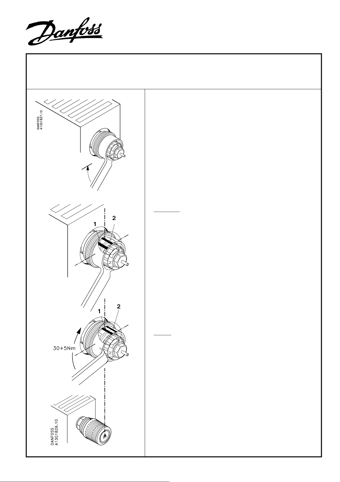
Screw the integrated valve into the radiator until it is hand tight
and it’s flange is butting onto the radiator connection. Then, using an open ended ring spanner, SW22, tighten the valve into
the radiator, this should be turned through an angle of 30°
equivalent to one of the notches on the valve body part on which
the spanner fits. This equates to a torque of 30 – 35 Nm.
013R9276
Reference
As the notches on the valve body cannot be seen with the spanner in place, it is a good idea to put two marks on the outside of
the ring spanner for guidance:
Mark “1” must be at top
Mark “2” should be spaced one notch distance away in a clockwise direction.
Zawór zintegrowany należy wkręcać ręcznie do oporu, aż jego
kołnierz oprze się o krawędź gniazda w grzejniku. Następnie
przy użyciu klucza nasadowego SW 22 należy dokręcić zawór o
dalsze 30 ° co odpowiada wypustowi na jego korpusie. Oznacza
to również moment 30 - 35 Nm.
Uwaga
Po założeniu klucza wypusty na zaworze są niewidoczne,
dlatego polecamy zaznaczyć ich położenie w postaci dwóch
znaków odniesienia na pierścieniu klucza:
Znak 1 powinien być u góry
Znak 2 powinien być oddalony o jeden wypust na zaworze w
kierunku zgodnym z ruchem wskazówek zegara.
CD-ST VI.16.D6.59 05-1999
Page 2
013L7270
5702420 035611 5702420 035611
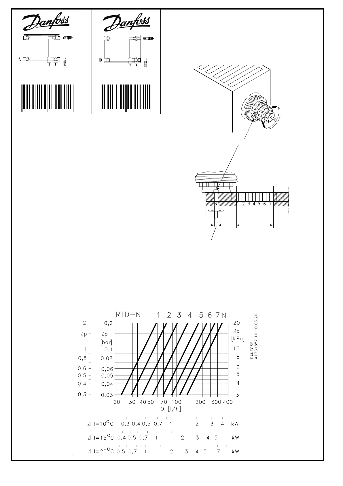
Pre-setting
The dimensioned setting values can be selected simply
and precisely without tools, prior to the fitting of the sensor. For this purpose, the red scale ring must be turned
to ensure that the presetting figure selected matches the
setting mark.
In setting “N” the preset value is fully open.
Detailed information is available from stockists or from
the radiator manufacturer.
Nastawa wtępna
Dobrana wartość nastawy wstępnej jest ustawiana
precyzyjnie i bez użycia jakiegokolwiek przyrządu. W
tym celu należy obrócić czerwony pierścień nastawczy
tak, aby odpowiednia cyfra znalazła się naprzeciw
punktu odniesienia na korpusie.zaworu. Nastawa N
odpowiada pełnemu otwarciu zaworu. Nastepnie
odbywa się montaż głowicy termostatycznej.
Informacje szczegółowe dostępne u dystrybutora lub
producenta grzejnika
013L7270
Reference mark - Znak odniesienia
Factory setting and one-pipe
setting
Nastawa fabryczna i dla
instalacji jednorurowej
Presetting area
Zakres ustawienia
wstępnego
Capacity: Information on pre-settings at the assembly site
Wydajności: informacja o nastawach na stanowisku montażowym
[mwg / m H2O]
CD-ST VI.16.D6.59 05-1999
 Loading...