

Page 1
Data Sheet
Flow director 013G1526 for tube segment
radiators - apply with integrated valve 013G1382
Application
Code Nos. and Technical
Data
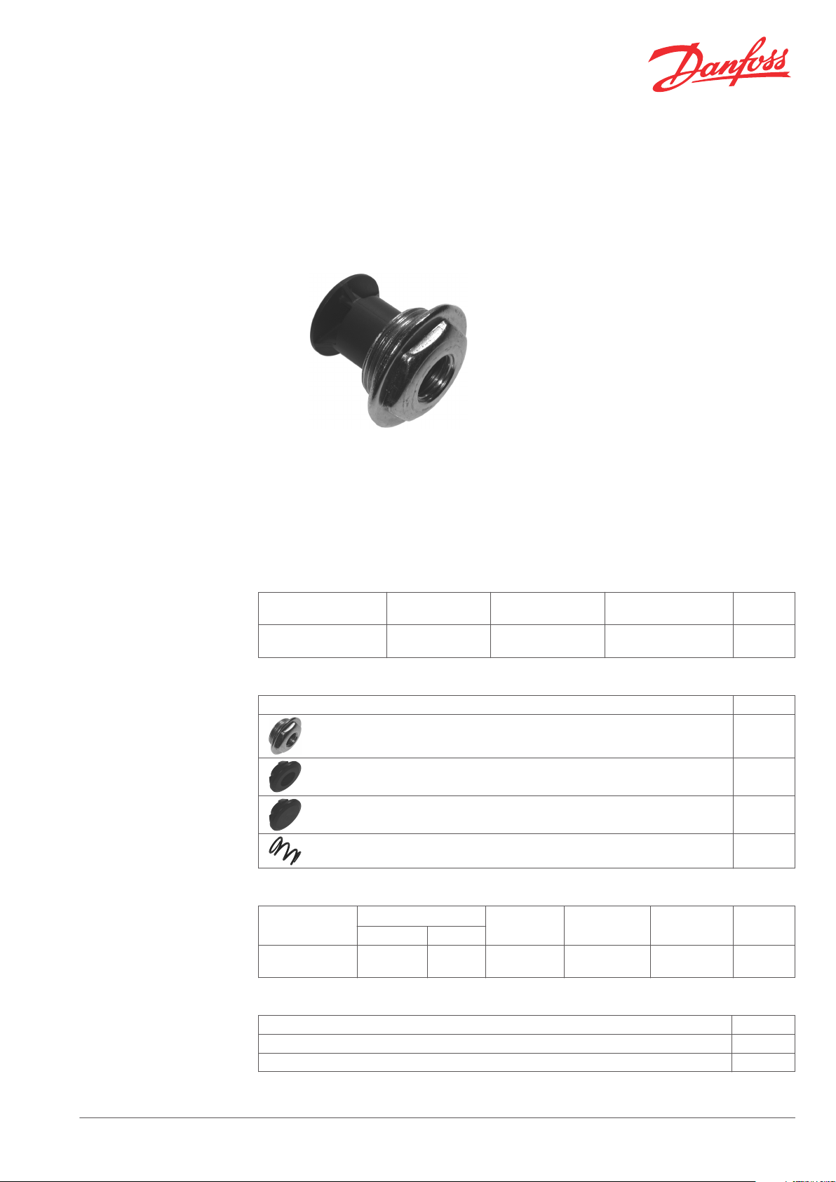
Flow director 013G1526
Flow director
Flow director type
For tube segment
radiators
The Danfoss flow director 013G1526 is designed
to be used with Danfoss integrated valve type
013G1382 for incorporation into tube segment
radiators.
Tube segment radiators are constructed by a
series of elements, which are welded together.
The first segment is used as inlet pipe, while
return is through the bottom of the second
segment.
When integrated valves are used in tube
segment radiators, the water flow needs to be
directed correctly through the valve to avoid
noise problems. This is made with the Danfoss
flow director.
Connection
radiator
1¼” ½” 120 °C 013G1526
Connection integr.
valve
Max. water
temperature
Code no.
Accessories and spare parts for flow director
Product Code no.
Flow director plug 013G1508
Open rubber plug 013G1533
Closed rubber plug 013G1534
Spring 013G1569
Integrated valve for flow director
Valve type
For Danfoss RA
type sensors
Accessories and spare parts for integrated valve 013G1382
Product Code no.
Gland seal 013G0290
Protection cap (red) 013G0951
Differential pressure
Recom. Technical
0.05-0.2 bar 0.6 bar 16 bar 10 bar 120 °C 013G1382
1)
Test pressure Work. pressure
Max. water
temp.
Code no.
Danfoss Heating Solutions VDCNG202 © Danfoss 02/2011 1
Page 2
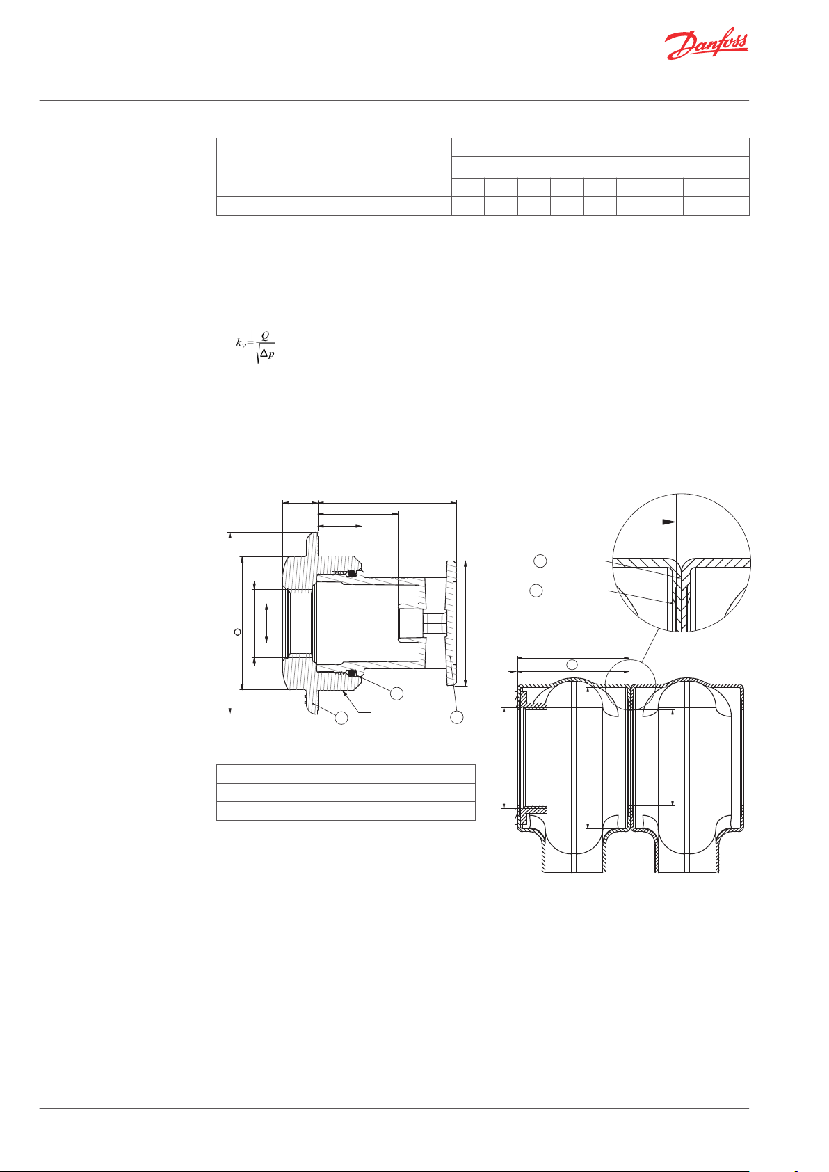
G1 1/4” ISO 228/1
10.8 42.7 ± 0.3
25
13.5
Ø56
41
G1/2” ISO 228/1
11.95
Ø38.5 ± 0.2
3
2
1
44.5 ± 1 mm
G1 1/4” ISO 228/1
min. Ø52 mm
Ø38-42 mm
REF.
2
1
3
Data Sheet Flow director 013G1526 for tube segment radiators - apply with integrated valve 013G1382
Pre-setting values, flow director + integrated valve
Flow director + integrated valve Presetting
kv-value
2)
1 2 3 4 5 6 7 N N
Flow director 013G1526 + RA 013G1382 0.14 0.18 0.26 0.32 0.45 0.55 0.69 0.84 1.18
1)
The technical differential pressure indicates the upper limit for a proper valve function. In most twopipe systems the recommended differential pressure is sufficient. In order to achieve a noiseless
function we recommend in smaller systems to apply automatic bypass valves or automatic balancing
valves. If pump differential pressure exceeds the recommended max. valve differential pressure it is
recommended that an automatic balancing valve type ASV-P/PV is added to the system.
2)
kv-values indicate the flow volume (Q) in m³/h at a pressure loss (Δp) across the valve of 1 bar ;
. At setting N, the kv-value in accordance with EN 215 can be stated as Xp = 2 K. At lower preset
values, Xp will be reduced until approximately Xp 0.5 at presetting 1. The table shows the average
measured values for integrated valves with radiator. The kvs-values indicate the valve capacity, when
the valve is fully open. If a remote temperature adjuster is used, the P-band is increased by a factor of
1.1. If a liquid filled radiator thermostat is used, the P-band is increased by a factor of 1.6.
k
vs
Design and Dimensions
Flow director 013G1522
Materials
Plug Nickel plated steel
1.
2. Flow director body PPS
3. O-ring EPDM
Radiator dimensions
1. Resistance seam welding
2. Burr at welding max. 0.5 mm
3. Gasket max. 1 mm after assembly
2 VDCNG202 © Danfoss 02/2011 Danfoss Heating Solutions
Page 3

[bar]
[mwg]
Q [l/h]
kW
kW
kW
10
8
6
5
4
3
2
∆p
1
0.8
0.6
0.5
0.4
0.3
0.2
0.1
1
0.8
0.6
0.5
0.4
0.3
0.2
∆p
0.1
0.08
0.06
0.05
0.04
0.03
0.02
0.01
1 2 3 4 5 6 7 N
100
80
60
50
40
30
20
∆p
10
8
6
5
4
3
0.2
1
[kPa]
5 7 10 20 30 40 50 70 100 200 300 400 500 700 1000 2000
∆ t = 10 ˚C
∆ t = 15 ˚C
∆ t = 20 ˚C
0.07 0.1 0.2 0.3 0.4 0.5 0.7 1 2 3 4 5 7 10 20
0.1 0.2 0.3 0.4 0.5 0.7 1 2 3 4 5 7 10 20 30
0.2 0.3 0.4 0.5 0.7 1 2 3 4 5 7 10 20 30 40
Data Sheet Flow director 013G1526 for tube segment radiators - apply with integrated valve 013G1382
Capacities
Flow director 013G1525/013G1557 + integrated valve 013G1382
Danfoss Heating Solutions VDCNG202 © Danfoss 02/2011 3
Page 4

Data Sheet Flow director 013G1526 for tube segment radiators - apply with integrated valve 013G1382
Danfoss A/S
Heating Solutions
Haarupvaenget 11
8600 Silkeborg
Denmark
Phone:+45 7488 8000
Fax: +45 7488 8100
Email: heating.solutions@danfoss.com
www.heating.danfoss.com
Danfoss can accept no responsibility for possible errors in catalogues, brochures and other printed material. Danfoss reserves the right to alter its products without notice. This also applies to products
already on order provided that such alterations can be made without subsequential changes being necessary in specifications already agreed. All trademarks in this material are property of the respective
companies. Danfoss and the Danfoss logotype are trademarks of Danfoss A/S. All rights reserved.
4 VDCNG202 © Danfoss 02/2011 Danfoss Heating Solutions
 Loading...