

Danby DDW1801MWP Installation

Dishwasher Installation
OWNER’S USE AND CARE GUIDE
GUIDE D’UTILISATION ET D'ENTRETIEN
Instructions d’installation
Instructions
lave-vaisselle
MODEL • MODÈLE
DDW1801MW / DDW1802EBLS
DANBY PRODUCTS LIMITED, ONTARIO, CANADA N1H 6Z9
DANBY PRODUCTS INC., FINDLAY, OHIO, USA 45840
2016.02.25
CONTENTS
TABLE DES MATIÈRES
BUILT IN DISHWASHER
Installation Instructions ...............................................1-19
• Dishwasher Safety
• Installation Requirements
• Installation instructions
LAVE-VAISSELLE ENCASTRÉ
Instructions d’installation...........................................20-38
• Sécurité de lave-vaisselle
• Exigences d’installation
• Instructions d’installation
CAUTION:
Read and follow all safety rules and operating
instructions before fi rst use of this product.
PRÉCAUTION :
Veuillez lire attentivement les consignes de
sécurité et les instructions d’utilisation avant
l’utilisation initiale de ce produit.
DISHWASHER SAFETY
WARNING:
Tip Over Hazard
• Do not use dishwasher until completely installed.
• Do not push down on open door.
• Doing so can result in serious injury or cuts.
Safety Tips:
• Slowly open dishwasher door while someone grasps the rear of the dishwasher. Remove shipping materials, drain
hose and lower rack. Close dishwasher door until latched.
• Observe all governing codes and ordinances.
• Install this dishwasher as specifi ed in these instructions.
• Installation should be performed by a qualifi ed service technician. The dishwasher must be installed to meet all electri-
cal and plumbing national and local codes and ordinances.
INSTALLATION REQUIREMENTS
Tools and Parts:
Gather the required tools and parts before starting installation.
Tools Needed for All Installations Parts Needed for All Installations
• Phillips screwdriver • 90° elbow with 3/8” N.P.T. external threads on one
end. (The other end must fi t your water supply line).
• Flat - blade screwdriver • Thread seal tape
• 5/16" and 1/4" nut drivers • 3 UL listed wire nuts
• Measuring tape or ruler • One 1-1/2”-2” screw type clamp
• 6" adjustable wrench
• Small level Parts Needed for New Installations
• Flashlight • Copper tubing (3/8” recommended)
• Shallow pan • Clamp connector to fi t a 7/8” (22.2 cm) diameter hole
• One 1-1/2” -2” screw type clamp if connecting to
waste-tee
Tools Needed for New Installations
• Electric drill with 1/2”, 3/4” and 1-1/2” hole saw bits
• Small tube cutter
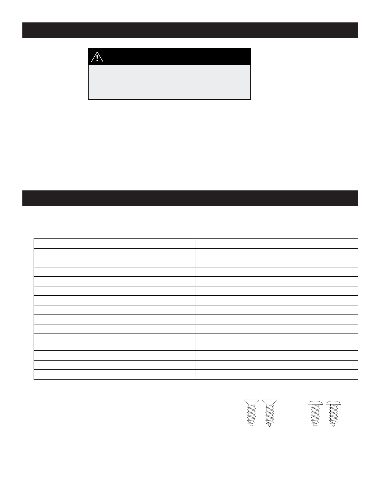
Parts Supplied:
A. 2 – # 8 x 5/8” Phillips fl at head wood screws
B. 4 – Phillips head, color matched toekick screws
Make sure these parts are included.
See separate parts list for accessories available for your dishwasher.
1
A
B
INSTALLATION REQUIREMENTS
Location Requirements:
• Do not run drain lines, water lines or electrical wiring where they can interfere with or contact dishwasher motors or
legs.
• The location where the dishwasher will be installed must provide clearance between motors and fl ooring. Motors
should not touch the fl oor.
• Do not install dishwasher over carpeted fl ooring. Protect dishwasher and water lines leading to dishwasher against
freezing. Damage from freezing is not covered by the warranty.
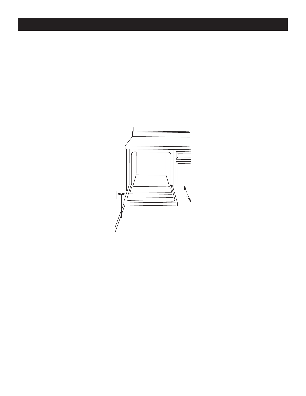
Check location where dishwasher will be installed. The location must provide:
1. Easy access to water, electricity and drain.
2. Convenient access for loading and unloading dishes. Corner locations require a 2” (5.1 cm) minimum clearance between the side of the dishwasher door and the wall or cabinet.
3. There must be a minimum of 25-5/8” (65.1 cm) in front of dishwasher to allow door to open fully.
Countertop
Dishwasher
25-5/8"
( 65.1 cm)
2" ( 5.1 cm)
Clearance for door
opening minimum
4. Square opening for proper operation and appearance.
5. Cabinet front perpendicular to fl oor.
6. Level fl oor. (If fl oor at front of opening is not level with fl oor at rear of opening, shims may be needed to level dish-
washer.) NOTE: To prevent shifting during dishwasher operation, shims must be securely attached to the
fl oor.
If dishwasher will be left unused for a period of time or in a location where it may be subject to freezing, have it winterized
by authorized service personnel.
Make sure pipes, wires and drain hose are within the shaded area shown in the “Cutout dimensions” section.
Helpful Tip: If the fl oor in the dishwasher opening is uneven (example: tile fl ooring only partway into opening)
you will need to take special care in measuring dimensions and in leveling dishwasher.
2
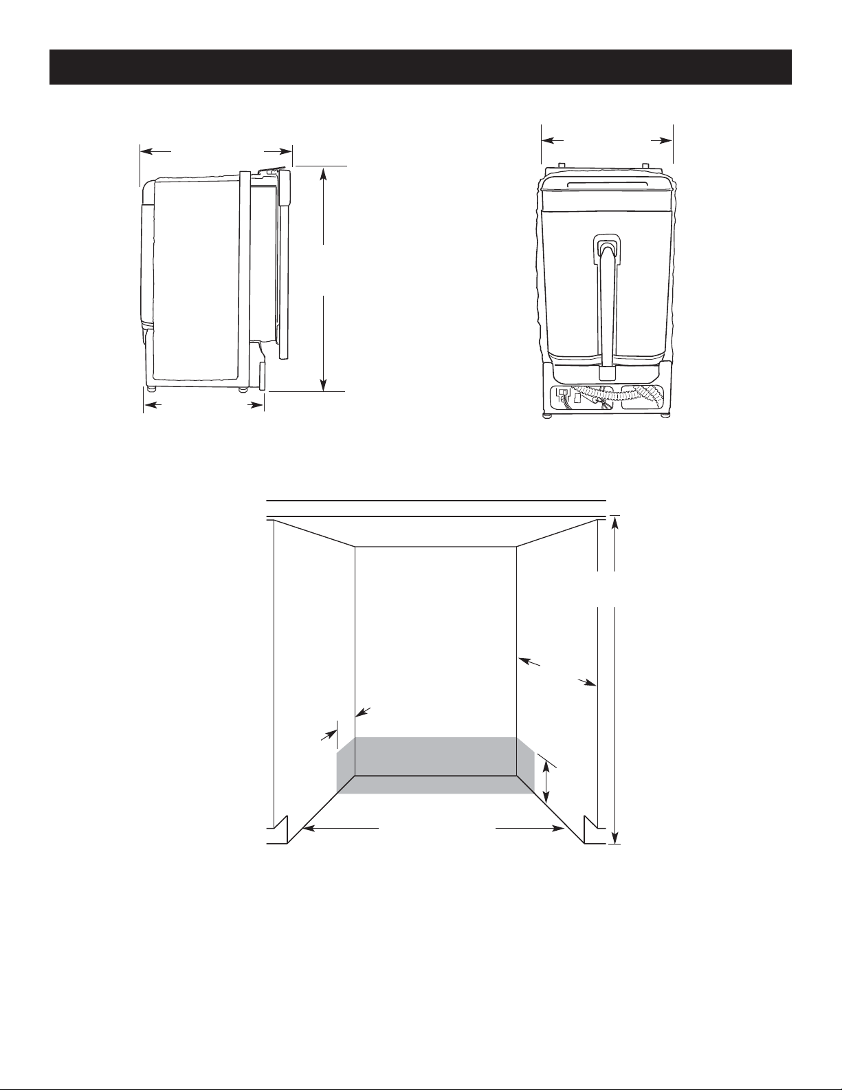
Product Dimensions:
Side View
* to front of
door frame
18" (45.7 cm)
Cut-out dimensions
INSTALLATION REQUIREMENTS
17-1/2" (44.5 cm) min.
21 1/4" (54cm)*
32-1/2"
(82.5 cm) min.
35" (88.9 cm)
max
18" (45.7 cm) max.
Rear View
ALL SURFACES
MUST BE FREE
FROM INTRUSIONS
34" to 35"
(86.4 cm to
88.9 cm)*
*Underside of countertop to
fl oor.
24"
(61 cm)
min.
Cut holes in shaded area of
cabinet walls or fl oor for plumb-
ing and electrical service.
4"
(10.2 cm)
6"
(15.2 cm)
17-5/8" (44.8 cm) min.
18" (45.7 cm) max.
Note: ADA installation, 32-1/2” (82.5 cm) beneath 34” (86.4 cm) high countertops may be accomplished by adjusting the toekick and leveling legs.
3
INSTALLATION INSTRUCTIONS
Drain Requirements:
• Use the new drain hose supplied with your dishwasher. If this is not long
enough, use a new drain hose with a maximum length of 10 feet (3.05 m)
that meets all current AHAM/IAPMO test standards, is resistant to heat and
detergent, use 5/8”(1.58cm) or 7/8”(2.2cm) inside diameter hose and a coupler to connect the two hose ends. Secure the connection with two clamps
• Connect drain hose to waste tee or disposer inlet above drain trap in house
plumbing and 32” (81.3 cm) minimum above the fl oor. It is recommended that
the drain hose either be looped up and securely fastened to the underside of
the counter, or be connected to an air gap.
• Use an air gap if the drain hose is connected to house plumbing lower than
18” (45.7 cm) above fl oor.
• Use 1/2” minimum I.D. drain line fi ttings.
• Do not connect drain lines from other devices to the dishwasher drain hose.
Water Supply Requirements:
• A hot water line with 20-120 psi (138-862 kPa) water pressure.
• 120°F (49°C) water at dishwasher.
• 3/8” O.D. copper tubing with compression fi tting or fl exible stainless steel braided fi ll line (1/2” minimum plastic tubing
is not recommended).
• A 90° elbow with 3/8” N.P.T. external pipe threads on one end.
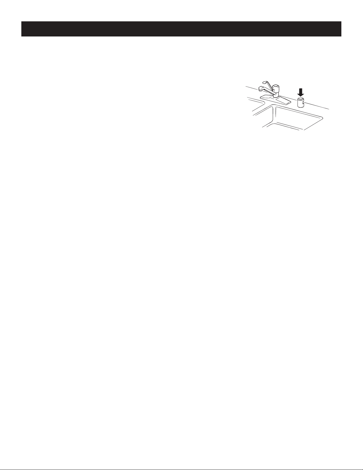
Air Gap
NOTE: Do not solder within 6” (15.2 cm) from water inlet valve.
Electrical Requirements:
Contact a qualifi ed electrician.
Ensure that the electrical installation is adequate and in conformance with all national and local codes and ordinances.
You must have:
• 120 volt, 60 Hz, AC-only, 15 or 20 amp., fused electrical supply.
• Wiring must be 2 wire with ground.
We recommend:
• A time-delay fuse or circuit breaker.
• A separate circuit.
If direct wiring dishwasher:
• Use fl exible, armored or non-metallic sheathed, copper wire with grounding wire that meets the wiring requirements
for your home and local codes and ordinances.
• Use strain relief method provided with house wiring junction box or install a U.L.-listed/CSA-certifi ed clamp connector
to the house wiring junction box. If using conduit, use a U.L.-listed/CSA-certifi ed conduit connector.
If connecting dishwasher with a power supply cord
• Use only a Power Supply Cord Kit marked for use with dishwashers.
• Power supply cord must plug into a mating three prong, grounded outlet, located in the cabinet next to the dishwasher
opening. Outlet must meet all local codes and ordinances.
4
INSTALLATION INSTRUCTIONS
WARNING:
Electrical Shock Hazard
• Disconnect electrical power at the fuse box or
circuit breaker box before installing dishwasher.
• Failure to do so can result in death or electrical
shock.
IMPORTANT: DISCONNECT POWER AND TURN OFF WATER SUPPLY.
Prepare Cabinet Opening Using Existing Utility Hookups:
• Follow the steps in this section if you are installing the dishwasher in an
existing cabinet opening with utility hookups.
• If you are installing the dishwasher in a cabinet opening that does not have
hookups, follow the steps under “Prepare cabinet opening where there are
no existing utility hookups” section.
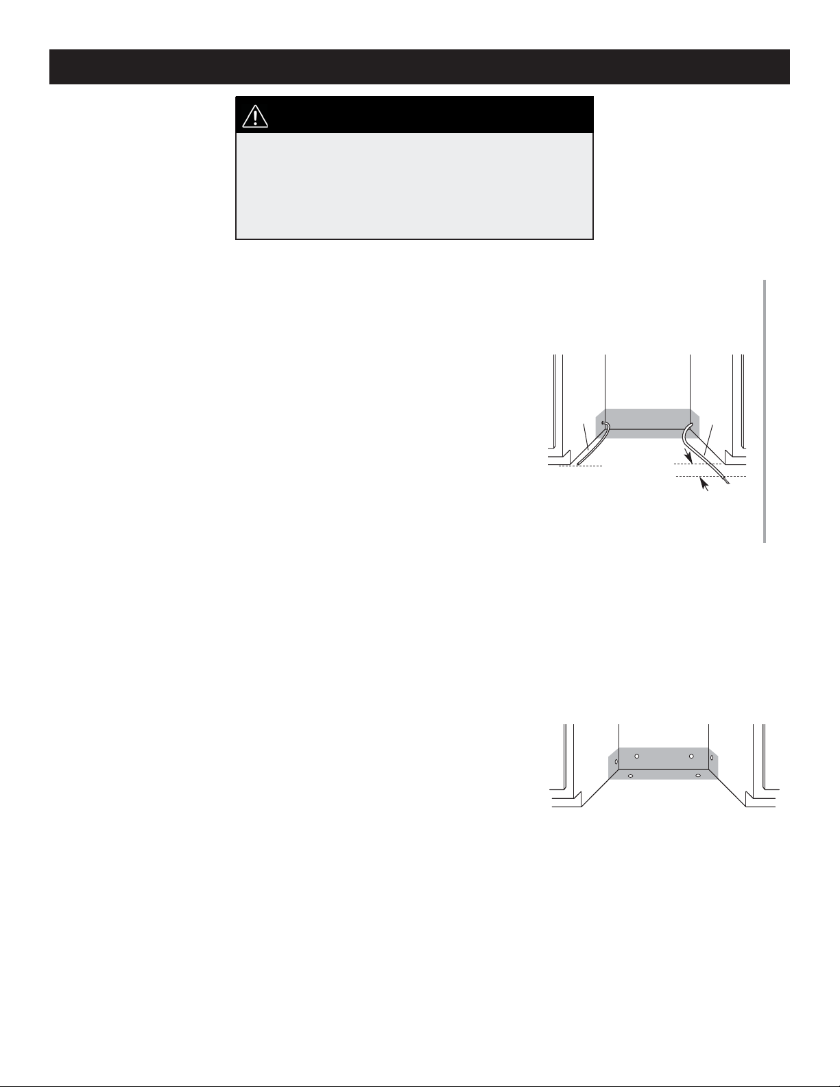
1. Check that the water line reaches to the front left of opening where the
water connection will be made.
2. Check that the direct wire reaches to the front right of opening where the
electrical connection will be made.
Water
Line
Direct
Wire
6" (15.2 cm)
If the water line and the direct wire reach far enough into the opening, proceed
to the next section “Install the drain hose.“ If they do not reach far enough,
follow the steps under “Prepare cabinet opening where there are no existing
utility hookups.”
Install the Drain Hose:
IMPORTANT: Always use a new drain hose even when installing a new
replacement dishwasher.
1. Drill a 1-1/2” (3.8 cm) diameter hole in cabinet wall or fl oor on the side of
the opening closest to the sink.
2. Connect drain hose to waste tee or waste disposer using one of the following methods:
• Option 1, Waste disposer – with air gap
• Option 2, No waste disposer – with air gap
• Option 3, Waste disposer – no air gap*
• Option 4, No waste disposer – no air gap*
*an air gap is recommended
Helpful Tip: To reduce the vibration of the hose, keep the hose away from the
fl oor and the edge of the hole where it passes through the cabinet.
5
INSTALLATION INSTRUCTIONS
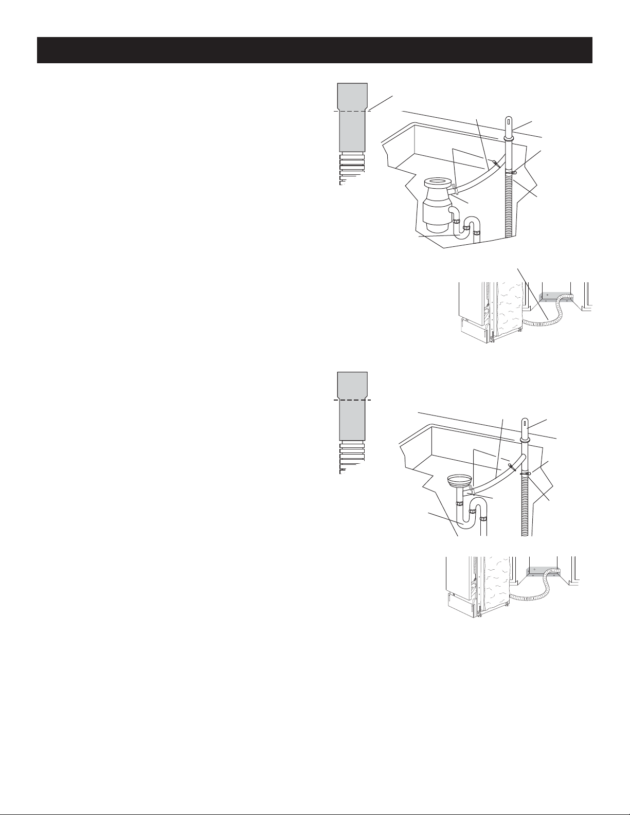
Option 1 - Waste disposer – with air gap:
1. Remove the disposer knockout plug. Cut end of drain hose
if needed (do not cut ribbed section).
2. Attach drain hose to air gap with large spring-type clamp.
If the drain hose was cut, use a 1-1/2” to 2” (3.8 to 5 cm)
screw-type clamp*.
3. Use a rubber hose connector* with spring or screwtype
clamps* to connect air gap to disposer inlet.
This connection must be before the drain trap and at least 20”
(50.8 cm) above the fl oor where dishwasher will be installed.
4. Insert drain hose through hole cut in cabinet to the front
center of opening where drain connection will be made.
* Parts should be available from a local plumbing supply store.
Option 2 - No waste disposer – with air gap:
1. Cut end of drain hose if needed (do not cut ribbed section).
2. Attach drain hose to air gap with large spring-type clamp.
If the drain hose was cut, use a 1-1/2” to 2” (3.8 to 5 cm)
screw-type clamp*.
3. Use a rubber hose connector* with spring or screw type
clamps* to connect air gap to waste tee. This connection
must be before the drain trap and at least 20” (50.8 cm)
above the fl oor where dishwasher will be installed.
4. Insert drain hose through hole cut in cabinet to the front
center of opening where drain connection will be made.
Drain Hose - Cut here
if needed
Spring or screw-type
clamps
Drain tap
Drain Hose - Cut here
if needed
Spring or screw-type
clamps
Drain tap
Rubber hose connector
Drain Hose
Rubber hose connector
Waste
Tee
Air Gap
Large spring-type
clamp
Drain hose
Air Gap
Large spring-type
clamp
Drain hose
Drain hose
6
INSTALLATION INSTRUCTIONS
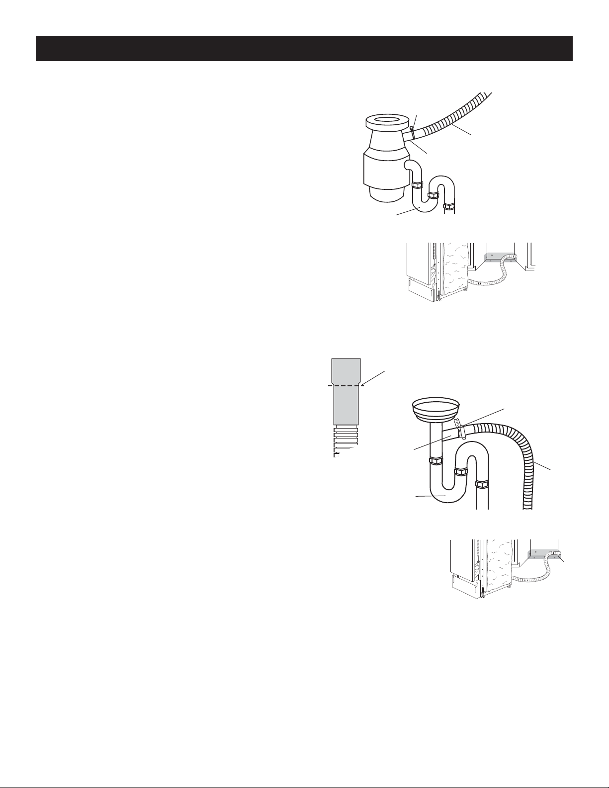
Option 3 - Waste disposer – no air gap:
1. Remove the disposer knockout plug. Do not cut end of drain
hose.
2. Attach drain hose to disposer inlet with large spring type
clamp. This connection must be before the drain trap and at
least 20” (50.8 cm) above the fl oor where dishwasher will be
installed. It is recommended that the drain hose be looped
up and securely fastened to the underside of the counter.
3. Insert drain hose through hole cut in cabinet to the front
center of opening where drain connection will be made.
Option 4, No waste disposer – no air gap:
1. Cut end of drain hose if needed (do not cut ribbed section).
2. Attach drain hose to waste tee with 1-1/2” to 2” (3.8 to 5
cm) screw-type clamp*. This connection must be before
the drain trap and at least 20” (50.8 cm) above the fl oor
where dishwasher will be installed. It is recommended that
the drain hose be looped up and securely fastened to the
underside of the counter.
3. Insert drain hose through hole cut in cabinet to the front
center of opening where drain connection will be made.
Large springtype clamp
Drain hose
Disposer inlet
Drain Trap
Drain Hose
Drain Hose - Cut here
if needed
Screw-type
clamp
Waste Tee
Drain Hose
* Parts should be available from a local plumbing supply store.
7
Drain Tap
Drain Hose
INSTALLATION INSTRUCTIONS
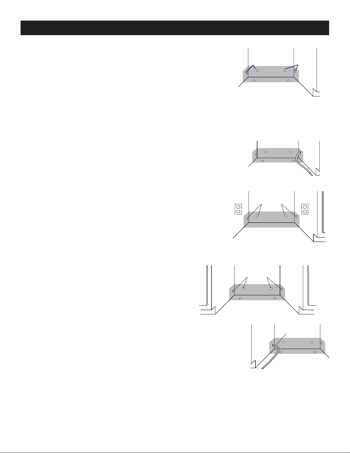
Prepare Cabinet Opening Where There are no Existing Utility Hookups
Electrical Connection:
Option 1 - Direct Wire Method:
Helpful Tip: Wiring the dishwasher will be easier if you route wire into the
cabinet opening from the right side.
1. Drill a 3/4” (1.9 cm) hole in right-hand cabinet side, rear or fl oor. Preferred and
optional locations are shown.
2. Wood cabinet: Sand hole until smooth. Metal cabinet: Cover hole with grommet, not provided.
3. Run wire into house wiring junction box.
4. Install a UL listed/CSA certifi ed clamp connector (strain relief) for fl exible-type
wire. If installing conduit, attach a UL listed/CSA certifi ed conduit connector to
the junction box.
5. Run other end of wire through cabinet hole. Cable must extend to the right
front of cabinet opening.
Option 2 - Power Supply Cord Method:
NOTE: A mating, three prong, ground-type wall receptacle is required in a
cabinet next to the dishwasher opening.
Optional Locations
Optional Locations
Preferred
Locations
Preferred
Locations
1. Drill a 1-1/2” (3.8 cm) hole in the cabinet rear or side. Preferred and optional
locations are shown.
2. Wood cabinet: Sand hole until smooth.
3. Metal cabinet: Cover hole with grommet.
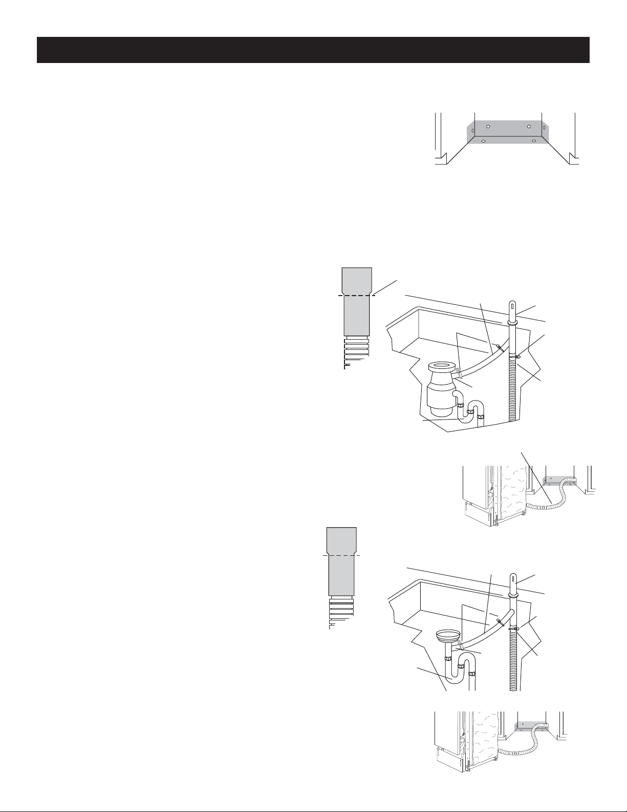
Install the Water Line:
Helpful Tip: Routing the water line through the left side of
cabinet opening will make water connection easier.
1. Drill a minimum 1/2” (1.3 cm) hole in the cabinet side, rear
or fl oor. Preferred and optional locations are shown.
2. Measure overall length of copper tubing required.
3. Attach copper tubing to the water line with a manual shutoff
valve.
4. Slowly feed copper tubing through hole in cabinet. Copper
tubing will bend and kink easily, so be gentle. The copper
tubing should be far enough into the cabinet opening to
connect it to dishwasher inlet on the front left of the dishwasher.
5. Turn water shutoff valve to “ON” position. Flush water into
a shallow pan to get rid of particles that may clog the inlet
valve.
6. Turn shutoff valve to “OFF” position.
Preferred
Locations
Optional
Locations
Copper
Tubing
8
INSTALLATION INSTRUCTIONS
Install the Drain Hose
IMPORTANT: Always use a new drain hose.
1. Drill a 1-1/2” (3.8 cm) diameter hole in cabinet wall or fl oor on the side of the
opening closest to the sink.
2. Connect drain hose to waste tee or waste disposer using one of the following
methods:
• Option 1, Waste disposer – with air gap
• Option 2, No waste disposer – with air gap
• Option 3, Waste disposer – no air gap*
• Option 4, No waste disposer – no air gap*
*an air gap is recommended
Helpful Tip: To reduce the vibration of the hose, keep the hose away from
the fl oor and the edge of the hole where it passes through the cabinet.
Option 1 - Waste disposer – with air gap:
1. Remove the disposer knockout plug. Cut end of drain
hose if needed (do not cut ribbed section).
2. Attach drain hose to air gap with large spring-type clamp.
If the drain hose was cut, use a 1-1/2” to 2” (3.8 to 5 cm)
screw-type clamp*.
3. Use a rubber hose connector* with spring or screw type
clamps* to connect air gap to disposer inlet. This connection must be before the drain trap and at least 20” (50.8
cm) above the fl oor where dishwasher will be installed.
4. Insert drain hose through hole cut in cabinet to the front
center of opening where drain connection will be made.
* Parts should be available from a local plumbing supply store.
Option 2 - No waste disposer – with air gap:
1. Cut end of drain hose if needed (do not cut ribbed section).
2. Attach drain hose to air gap with large spring-type clamp.
If the drain hose was cut, use a 1-1/2” to 2” (3.8 to 5 cm)
screw-type clamp*.
3. Use a rubber hose connector* with spring or screwtype
clamps* to connect air gap to waste tee. This connection
must be before the drain trap and at least 20” (50.8 cm)
above the fl oor where dishwasher will be installed.
4. Insert drain hose through hole cut in cabinet to the frontcenter of opening where drain connection will be made.
Drain Hose - Cut here
if needed
Spring or screw-type
clamps
Drain tap
Drain Hose - Cut here
if needed
Spring or screw-type
clamps
Drain tap
Rubber hose connector
Drain Hose
Rubber hose connector
Waste
Tee
Air Gap
Large spring-type
clamp
Drain hose
Air Gap
Large spring-type
clamp
Drain hose
* Parts should be available from a local plumbing supply store.
9
Drain hose
INSTALLATION INSTRUCTIONS
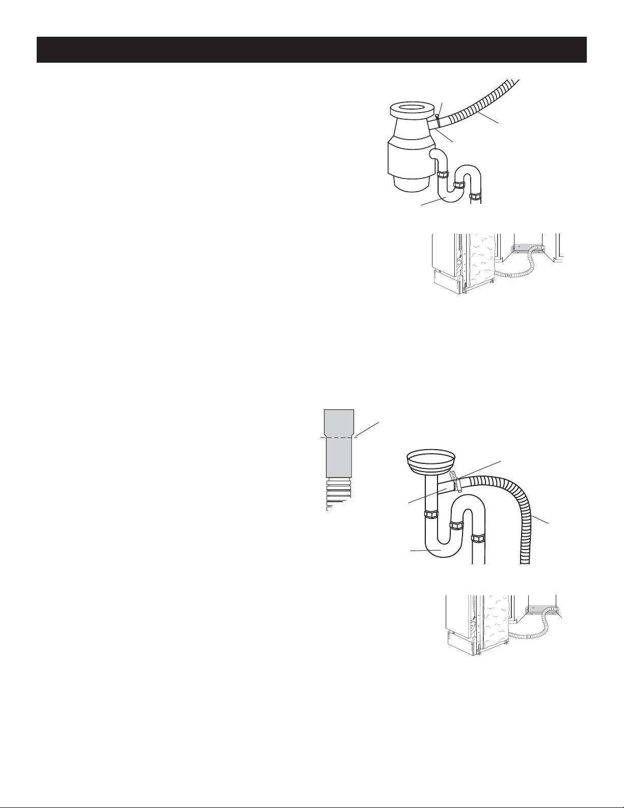
Option 3 - Waste Disposer - No Air Gap:
1. Remove the disposer knockout plug. Do not cut end of drain hose.
2. Attach drain hose to disposer inlet with large spring type clamp. This
connection must be before the drain trap and at least 20” (50.8 cm)
above the fl oor where dishwasher will be installed. It is recommended
that the drain hose be looped up and securely fastened to the underside of the counter.
3. Insert drain hose through hole cut in cabinet to the front center of
opening where drain connection will be made.
Large springtype clamp
Drain hose
Disposer inlet
Drain Trap
Drain Hose
Option 4 - No waste disposer – no air gap:
1. Cut end of drain hose if needed (do not cut
ribbed section).
2. Attach drain hose to waste tee with 1-1/2” to 2”
(3.8 to 5 cm) screw-type clamp*. This connection
must be before the drain trap and at least 20”
(50.8 cm) above the fl oor where dishwasher will
be installed. It is recommended that the drain
hose be looped up and securely fastened to the
underside of the counter.
3. Insert drain hose through hole cut in cabinet to
the front center of opening where drain connection will be made.
* Parts should be available from a local plumbing
supply store.
Drain Hose - Cut here
if needed
Screw-type
clamp
Waste Tee
Drain Hose
Drain Tap
Drain Hose
10
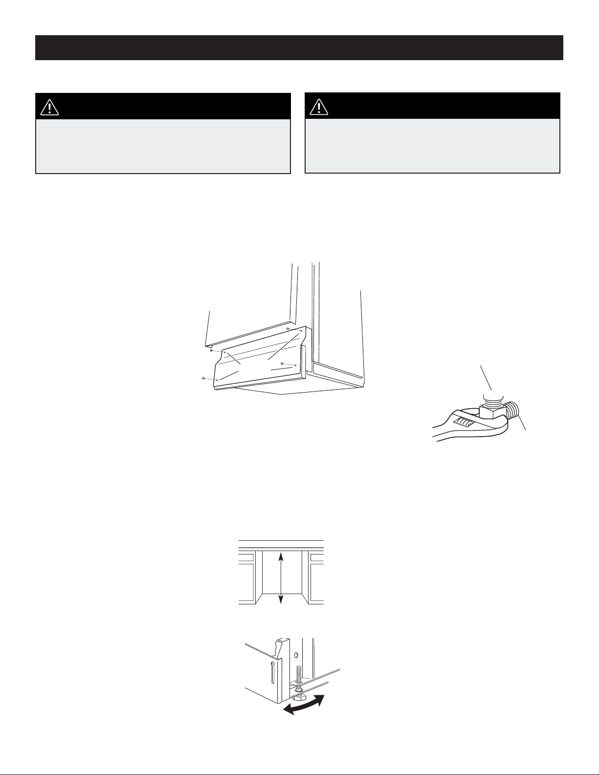
Prepare Dishwasher:
INSTALLATION INSTRUCTIONS
WARNING:
Tip Over Hazard
• Do not use dishwasher until completely installed.
• Do not push down on open door.
• Doing so can result in serious injury or cuts.
Helpful Tip: Put cardboard under dishwasher until it is installed in cabinet opening. The cardboard will help protect fl oor
covering during installation.
1. Grasp sides of dishwasher door frame and put dishwasher on its back.
2. Remove four screws attaching toekick panel and lower panel to dishwasher using a 1/4” hex socket, nut driver or
Phillips screwdriver.
3. Remove panels and set panels aside on a protective surface.
4 toekick
screws
WARNING:
Excessive Weight Hazard
• Use two or more people to move and install dishwasher.
• Failure to do so can result in back or other injury.
Water inlet
valve
4. Apply thread seal tape to 90° elbow fi tting and connect fi tting to water inlet valve.
5. Tighten elbow until snug, and be sure that it faces to the rear.
Elbow
6. Remove terminal box cover. – If you are direct wiring: install a U.L.-listed/CSA certifi ed clamp connector to the ter-
minal box. If using conduit, use a U.L.-listed/CSA-certifi ed conduit connector. – If you are installing a power supply
cord kit, do so now, following kit instructions. The power supply cord kit must be U.L.-listed and marked for use with
dishwashers.
7. Measure height of cabinet opening from underside of countertop to fl oor where dishwasher will be installed (you need
the lowest point).
8. Extend leveling legs out from the dishwasher base, 1/4” less than opening height.
Levelling
Leg
11
 Loading...