

Page 1
Matside® Jr.
LED Wrestling Scoreboards
Display Manual
ED-15023 Rev 1 – 9 June 2010
Models
WR-2101
WR-2104
WR-2102
WR-2105
WR-2103
WR-2106
Page 2

Page 3

ED-15023
Please fill in the information below to use for reference when calling Daktronics for assistance.
Display Serial No. _______________________________________________________
Display Model No. _______________________________________________________
Date Installed ___________________________________________________________
Product 1237
Rev 1 – 9 June 2010
DAKTRONICS, INC.
Copyright 2004-2010
All rights reserved. While every precaution has been taken in the preparation of this manual, the publisher
assumes no responsibility for errors or omissions. No part of this book covered by the copyrights hereon may be
reproduced or copied in any form or by any means – graphic, electronic, or mechanical, including photocopying,
taping, or information storage and retrieval systems – without written permission of the publisher.
All Sport®, Matside®, PanaView®, and Pro Sport® are trademarks of Daktronics, Inc. Other trademarks used in this manual are
the property of their respective owners.
Page 4

Page 5

Table of Contents
Section 1: Introduction ................................................................................................................. 1
1.1 Resources .................................................................................................................................. 1
1.2 Daktronics Nomenclature ...................................................................................................... 2
1.3 Model Number ........................................................................................................................ 3
1.4 Scoreboard Controllers ........................................................................................................... 3
1.5 Product Safety Approval........................................................................................................ 3
Section 2: Specifications ............................................................................................................. 5
Section 3: Mechanical & Electrical Installation .......................................................................... 7
3.1 Mechanical Installation .......................................................................................................... 7
3.2 Electrical Installation .............................................................................................................. 7
Power ................................................................................................................................. 7
Signal ................................................................................................................................. 8
Section 4: Scoreboard Troubleshooting .................................................................................... 9
4.1 Troubleshooting Table ............................................................................................................ 9
4.2 Component Location & Access ........................................................................................... 10
4.3 Replacing Digits .................................................................................................................... 11
4.4 LED Drivers ........................................................................................................................... 11
Replacing a Driver ......................................................................................................... 12
Setting the Driver Address ........................................................................................... 13
4.5 Segmentation and Digit Designation .................................................................................. 13
4.6 Schematics .............................................................................................................................. 13
4.7 Replacement Parts ................................................................................................................. 13
4.8 Daktronics Exchange and Repair & Return Programs ..................................................... 14
Exchange Program ......................................................................................................... 14
Repair & Return Program ............................................................................................. 15
Daktronics Warranty and Limitation of Liability ...................................................... 16
Section 5: Additional Scoreboard Features ............................................................................. 17
5.1 Horns ...................................................................................................................................... 17
Adjusting Horn Volume................................................................................................ 17
5.2 Changeable Captions ............................................................................................................ 17
5.3 Ad Panels ............................................................................................................................... 17
Appendix A: Reference Drawings ................................................................................................. 19
Appendix B: Daktronics Warranty and Limitation of Liability .................................................... 21
Page 6

Page 7
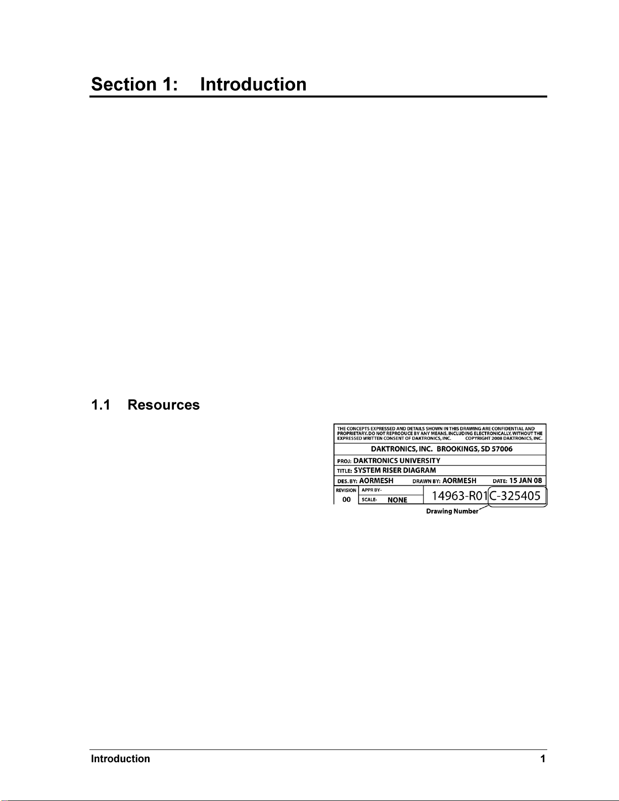
Figure 1: Daktronics Drawing Label
This manual explains the installation of Daktronics Matside Jr.LED wrestling scoreboards and
provides details for maintenance and troubleshooting. For additional information regarding the
safety, installation, operation, or service of this system, refer to the telephone numbers listed in
Section 4.8. This manual is not specific to a particular installation.
Important Safeguards:
Please read and understand all instructions before beginning the installation process.
Do not drop control equipment or allow it to get wet.
Do not disassemble control equipment or electronic controls of the display; failure to
follow this safeguard will make the warranty null and void.
Disconnect display power when not in use or when servicing.
Disconnect display power before servicing power supplies to avoid electrical shock.
Power supplies run on high voltage and may cause physical injury if touched while
powered.
Do not modify the scoreboard structure or attach any panels or coverings to the
scoreboard without the express written consent of Daktronics, Inc.
Project-specific information takes precedence over any other general information found in
this manual.
Figure 1 illustrates a Daktronics drawing
label. The drawing number is located in the
lower-right corner of a drawing. This
manual refers to drawings by listing the last
set of digits and the letter preceding them.
In the example, the drawing would be
referred to as Drawing C-325405.
Reference Drawing:
System Riser Diagram ........................................................................... Drawing C-325405
Daktronics identifies manuals by the DD or ED number located on the cover page of each
manual. For example, this manual would be referred to as ED-15023.
Page 8
Main Component Labels
Part Type
Part Number
Individual circuit board
0P-XXXX-XXXX
Assembly; a collection of circuit boards
0A-XXXX-XXXX
Wire or cable
W-XXXX
Fuse
F-XXXX
Transformer
T-XXXX
Metal part
M-XXX
Fabricated metal assembly
0S-XXXXXX
Specially ordered part
PR-XXXXX-X
Accessory Labels
Component
Label
Termination block for power
or signal cable
TBXX
Grounding point
EXX
Power or signal jack
JXX
Power or signal plug for the
opposite jack
PXX
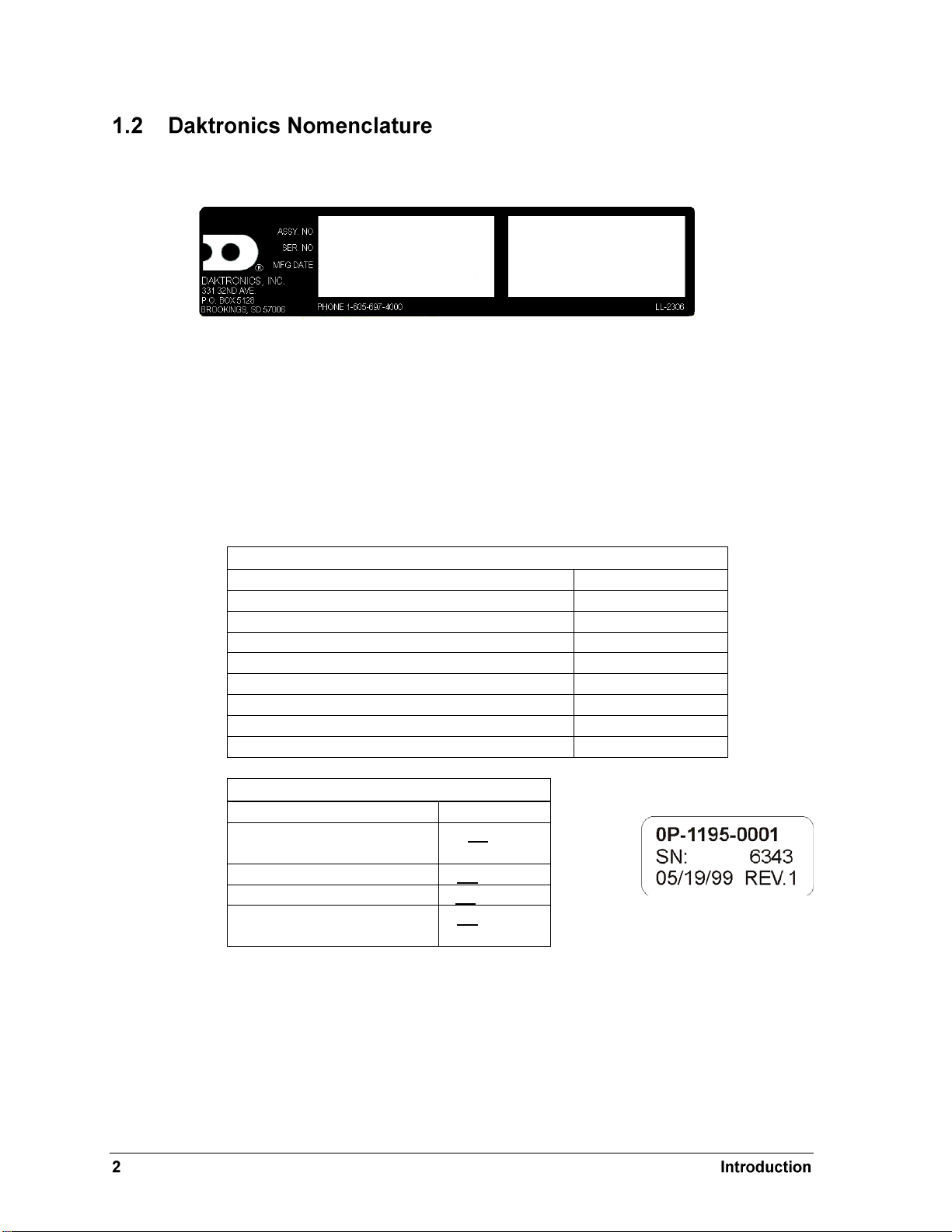
Figure 2: Scoreboard ID Label
Figure 3: Typical Label
Serial and model numbers can be found on the ID label on the display as shown in Figure 2.
Please list the model number, display serial number, and the date this display became
operational in the blanks provided on the second page of this manual. When calling
Daktronics customer service, please have this information available to ensure the request is
serviced as quickly as possible.
Most components within this display carry a white label that lists the part number of the unit.
If a component is not found in the Replacement Parts List in Section 4.7, use the label to order
a replacement. Figure 3 illustrates a typical label. The part number is in bold.
Following the Replacement Parts List is the Daktronics Exchange Policy and the Repair &
Return Program. Refer to these instructions if replacing or repairing any display component.
Page 9
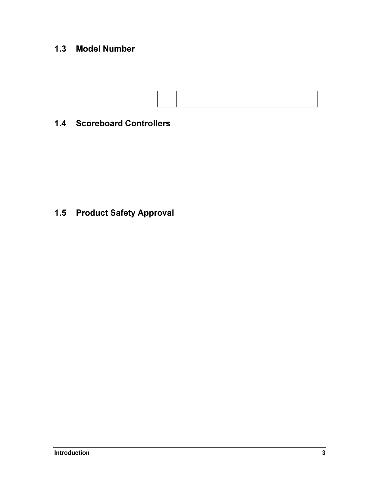
WR
Wrestling
-13
indoor scoreboards, 120 V AC, PanaView® digits
-14
indoor scoreboards, 230 V AC, PanaView® digits
Daktronics scoreboards are differentiated by their model numbers and two-letter prefixes for
each sport. Most Daktronics scoreboards also carry a two-number suffix that refers to the type
of power supply and digit color. Refer to the following tables:
Daktronics Matside scoreboards are designed for use with the All Sport® 1600 and 5000 series
control consoles. Both consoles use keyboard overlays (sport inserts) to control numerous
sports and scoreboard models. Refer to the following manuals for operating instructions:
All Sport 1600 Series Control Console Operation Manual (ED-12462)
All Sport 5000 Series Control Console Operation Manual (ED-11976)
These control console manuals are available online at www.daktronics.com/manuals.
Daktronics scoreboards are ETL-listed, tested to CSA standards and CE-labeled for indoor
use. Contact Daktronics with any questions regarding the testing procedures.
Page 10

Page 11
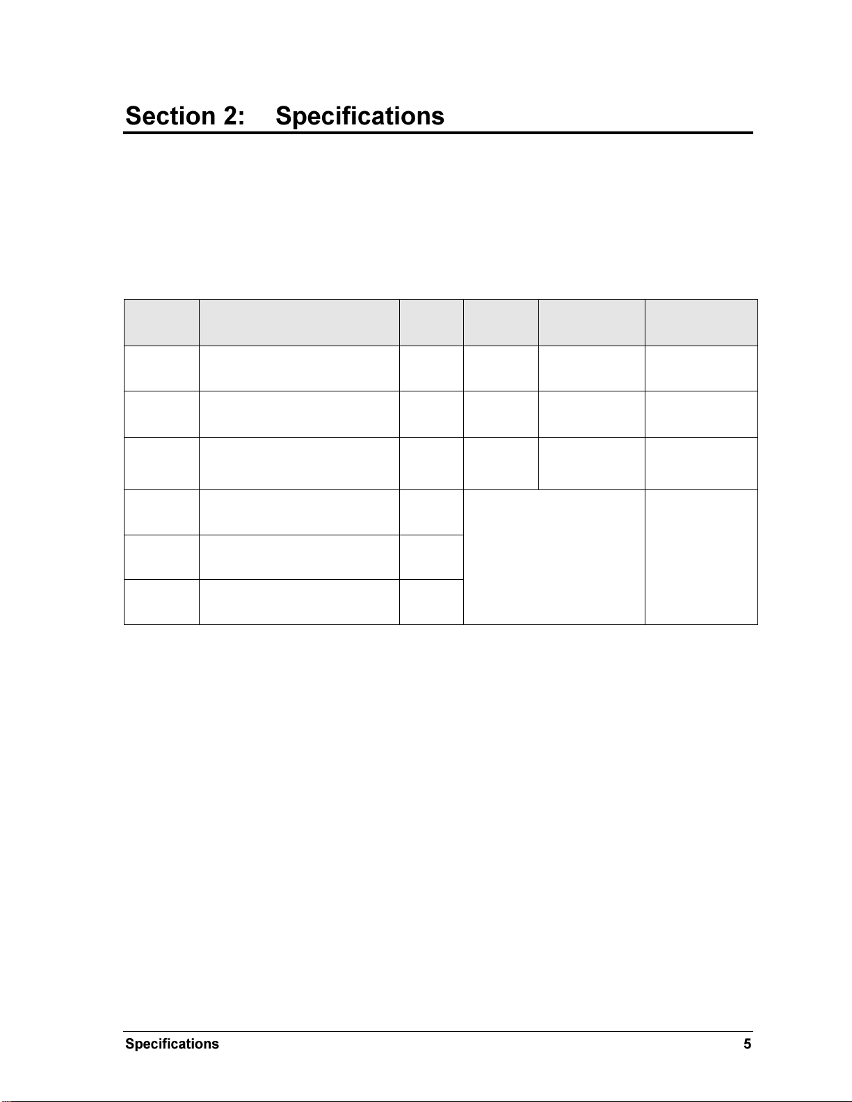
Model
Dimensions:
Height, Width, Depth
Weight:
Watts
Amps
120 / 230 V AC
Driver #
& Address
WR-2101
H 1'-9", W 2'-0" , D 7"
(533 mm, 610 mm, 178 mm)
25 lb
(11 kg)
100 W
0.85 A / 0.4 A
A1 104
WR-2102
H 1'-9", W 2'-0", D 7"
(533 mm, 610 mm, 178 mm)
30 lb
(14 kg)
100 W
0.85 A / 0.4 A
A1 104
WR-2103
H 1'-10", W 2'-3", D 2'-1"
(559 mm, 679 mm, 635 mm)
45 lb
(20 kg)
100 W
0.85 A / 0.4 A
A1 104
WR-2104
H 0'-9", W 2'-0", D 7"
(229 mm, 610 mm, 178 mm)
10 lb
(4.5 kg)
WR-2101, WR-2102, or
WR-2103 scoreboard
required to provide
operation of digits
Driver located
in WR-2101,
WR-2102, or
WR-2103
scoreboard
WR-2105
H 0'-9", W 2'-0", D 7"
(229 mm, 610 mm, 178 mm)
10 lb
(4.5 kg)
WR-2105
H 0'-10", W 2'-3", D 2'-1"
(254 mm, 679 mm, 635 mm)
20 lb
(9 kg)
The chart on the following pages details all of the mechanical specifications, circuit specifications and
power requirements for each display in this manual. Models are listed in alphanumeric order.
Notes:
1) All displays require a 120 V AC, 15 A circuit. Displays with a 230 V A C power
requirement are also available.
2) Signal wire must be minimum of 22 AWG with shield. Daktronics recommends W-1614.
Page 12

Page 13
Reference Drawings:
Mechanical Spec, WR-2101-13 ............................................................. Drawing A-220834
Mechanical Spec, WR-2102-13 ............................................................. Drawing A-220815
Mechanical Spec, WR-2103-13 ............................................................. Drawing A-220856
Mechanical Spec, WR-2104, 2105, 2106 .............................................. Drawing A-220904
All Daktronics Matside Jr. wrestling scoreboards may be displayed on the floor on a table, or
mounted on an optional tripod. Use only the tripod (part number A-1580) and adapter (HS-
1306) supplied by Daktronics. Drawings A-220815, A-220834, A-220856, and A-220904 in
Appendix A show how to mount the display on a tripod. Locate the holes on the bottom of
the scoreboard and secure the display to the tripod adaptor using the hardware provided.
The single-sided wrestling scoreboard (WR-2101) may also be wall mounted (the two- and
three-sided scoreboards in this manual cannot). Refer to Drawing A-220834 for mounting
keyhole locations on the back of the display. Due to the variety of wall materials used in
sports facilities, Daktronics cannot anticipate a user‟s needs or provide mounting hardware
suitable for every installation. Mounting hardware may be purchased at a local hardware
store. Choose a method of installation that will safely support the weight of the display.
Note: Do not use the carrying handle to permanently suspend the display.
Reference Drawings:
Electrical/Signal Spec, WR-2101-13 ...................................................... Drawing A-220850
Electrical/Signal Spec, WR-2102-13 ...................................................... Drawing A-220821
Electrical/Signal Spec, WR-2103-13 ...................................................... Drawing A-220875
Electrical/Signal Spec, WR-2104, 2105, 2106 ....................................... Drawing A-220903
Electrical installation involves the routing of power and control signal wiring to the displays.
Control signal cable is not provided as part of this system; it can be purchased locally or from
Daktronics.
Refer to Drawings A-220850, A-220821, and A-220875 in Appendix A for detailed power and
signal connection diagrams for each wrestling scoreboard model.
Each display comes equipped with a 120V AC, three-prong plug. Install a grounded
receptacle near the equipment and make certain that the power cord can easily reach it.
The control console requires a 120 V AC receptacle and uses less than 1 A of power.
Displays operating on 230 V AC are also available, and they are shipped equipped with a
universal power plug.
Page 14

Models WR-2104, WR-2105, and WR-2106 are actually slave units that receive power and
signal from the base scoreboard. Refer to Drawing A-220903 in Appendix A for illustration
on how the units are connected.
1. Route the signal cable from the display to the control location.
2. Plug the signal cable into the J31 SIGNAL IN jack on the side of the display.
3. Plug the other end of the signal into the jack on the controller (J1 or J2 on All Sport
1600; J1, J2, or J3 on All Sport 5000).
4. Refer to the electrical and signal specification drawings in Appendix A for additional
information and typical system setup examples.
Special note to users of All Sport® 4000 and Pro Sport® 6000 Control Consoles:
Current standard models in the Daktronics Matside Jr. wrestling display lines are factory
configured to operate only with the All Sport 1600 and 5000 series control consoles. If one of
these standard scoreboards is sent as a replacement, the address plug must be removed from
the scoreboard to properly receive signal from older controllers. Simply unplug the address
plug, P19, from connector J19 on the LED driver (refer to Section 4.4). If any problems occur
with this procedure, contact the Daktronics Help Desk or Project Manager.
Page 15

Problem
Possible Cause
Solution/Items to Check
Scoreboard doesn’t light
and console doesn’t work
No power to the scoreboard
Check that the main circuit breaker
for the scoreboard is on.
Check that the scoreboard is
receiving the correct 120 (or 230) V
AC power (see Section 2).
No power to console
Ensure the console is plugged into
a 120 (or 230) V AC power supply.
Swap the console with one known
to work correctly, and enter the
proper sport code to test. Replace
console if necessary.
Scoreboard digits don’t light,
but console works
No wired signal from console
Check that the scoreboard is
receiving the correct 120 (or 230) V
AC power (see Section 2).
Check that the red DS2 LED on the
driver lights up when sending
commands from the control
console (see Section 4.4).
No signal to driver
Check that the scoreboard is
receiving the correct 120 (or 230) V
AC power (see Section 2).
Check that the red DS2 LED on the
driver lights up when sending
commands from the control
console (see Section 4.4).
IMPORTANT NOTES:
1. Always disconnect power before doing any repair work on the scoreboard.
2. Permit only qualified service personnel to access internal display electronics.
3. Disconnect power when not using the scoreboard.
The table below lists potential problems with the scoreboard and indicates possible causes
and corrective actions. This list does not include every symptom that may be encountered,
but it does present several of the most common situations that may occur.
Many of the solutions offered below provide references to other sections within this manual
or to supplemental product manuals with further detail on how to fix the problem.
If a problem occurs that is not listed or that cannot be resolved using the solutions in the
following table, contact Daktronics using the information provided in Section 4.8.
Page 16

Problem
Possible Cause
Solution/Items to Check
Swap the driver with one known to
work correctly and with the same
part number to verify the problem.
Replace if necessary
(see Section 4.4).
No power to driver
Check that the green DS1 LED on
the driver is always lit up when the
scoreboard is powered on
(see Section 4.4).
Scoreboard digits light, but
not in the correct order
Incorrect sport code
Ensure the correct sport code is
being used for the scoreboard
model. Refer to the operation
manual for the console being used
(see Section 1.4).
Incorrect driver address
Check that the scoreboard driver(s)
are set to the correct address(es)
(see Section 4.4)
Scoreboard digits light,
console works, but no
display on scoreboard
No wired signal from console
(See solution on previous page)
Bad/damaged field wiring
Check that the red DS2 LED on the
driver lights up when sending
commands from the control
console (see Section 4.4)
Scoreboard works, but some
LEDs always stay on
Short in digit or indicator circuit
Swap the digit/indicator with one
known to work correctly to verify
the problem. Replace if necessary
(see Section 4.3).
Scoreboard works, but some
LEDs do not light or they
blink
Bad connection
Verify the Mate-N-Lok connector
on the back of the digit circuit
board is secure (see Section 4.3).
Bad digit or driver
Swap the digit/driver with one
known to work correctly to verify
the problem. Replace if necessary
(see Section 4.3 for digits or
Section 4.4 for drivers).
Scoreboard works, but some
digits do not light
Bad digit or driver
(see solution above)
Incorrect sport code
(see solution above)
Incorrect driver address
(see solution above)
To access the driver, digits, or other internal components, remove the screws securing the
face panel(s) to the scoreboard. Some panels are hinged at the bottom and will swing
downward.
Scoreboard Troubleshooting
Page 17

LED
Color
Function
Operation
Summary
DS1
Green
Power
Steady on
DS1 will be on and steady to
indicate the driver has power.
DS2
Red
Signal RX
Steady on
or blinking
DS2 will be on or blinking when the
driver is receiving a signal and off
when there is no signal.
DS3
Amber
Status
Blinking
DS7 will be blinking at one second
intervals to indicate the driver is
running.
LEDs are embedded in a circuit board that is mounted to the back of the face panel. Do not
attempt to remove individual LEDs. In the case of a malfunctioning LED, replace the entire
digit circuit board.
To replace a digit circuit board:
1. Open the face panel as described in Section 4.2.
2. Disconnect the power/signal plug from the back of the digit by squeezing together
the locking tabs and pulling the connector free.
3. Use a
4. Position a new digit over the spacers and studs.
5. Tighten the nuts.
6. Reconnect the power/signal connector.
7. Close and secure the face panel, then power up and test the scoreboard to see if
9
/32" nut driver to remove the nuts securing the digits to the inside of the panel,
and then lift the digit off the spacers and standoff studs.
Note: This is a keyed connector and it will attach in one way only. Do not attempt to
force the connection.
changing the digit has resolved the problem.
Reference Drawings:
Address Table, 1 Through 128 ............................................................... Drawing A-115078
LED Driver, 16 Column .......................................................................... Drawing A-126174
The LED drivers perform the task of switching digits on and off within the scoreboard.
Refer to the electrical and signal specifications drawings in Appendix A to determine the
location of the driver in a particular scoreboard model. See also Drawing A-126174 for
detailed driver pin out/switch specifications.
When troubleshooting driver problems, three LEDs labeled DS1, DS2, and DS3 in Figure 4,
provide the following diagnostic information:
Page 18

Figure 4: Driver Status Indicators
Note: While it is necessary to have the scoreboard powered on to check the LED
indicators, always disconnect scoreboard power before servicing.
To replace a driver:
1. Open the digit panel as described in Section 4.2.
2. Disconnect all connectors from the driver by squeezing together the locking tabs and
pulling the connectors free.
Note: It may be helpful to label the cables to know which cable goes to which
connector when reattaching the driver.
3. Remove the screws or nuts securing the driver to the inside of the enclosure.
4. Carefully lift the driver from the display and place it on a clean, flat surface.
5. Position a new driver over the screws and tighten the nuts.
6. Reconnect all power/signal connectors.
Note: The connectors are keyed and will attach in one way only. Do not attempt to
force the connections.
7. Ensure the driver is set to the correct address (refer to Setting the Driver Address).
8. Close and secure the face panel, then power up and test the scoreboard to see if
changing the driver has resolved the problem.
Scoreboard Troubleshooting
Page 19

Description
Daktronics Part #
16 Column LED Driver II
0P-1150-0126
Digit, 5" green 7 segment LED
0P-1150-0062
Digit, 5" amber 7 segment LED
0P-1150-0081
Digit, 5" red 7 segment LED
0P-1150-0200
Indicator, 5" amber LED
0P-1150-0247
Indicator, 5" red LED
0P-1150-0249
Indicator, 5" green LED
0P-1150-0250
Horn, 120V w/ Cap.
0A-1152-0332
Horn Interface Card
0P-1192-0399
Figure 5: Driver Address Jack J19
Since the same LED drivers can be used for many
scoreboard models, each driver must be set to
receive the correct signal input, or address, for the
model being used. This address is set with jumper
wires in a 12-pin plug which mates with jack J19
on the driver (Figure 5).
When setting the driver address, refer to Drawing
A-115078 in Appendix A for a listing of the
wire/pin connections for driver addresses 1 – 128.
Note: All scoreboards in this manual should
be set to address “104”.
In each digit, certain LEDs always go on and off together. These groupings of LEDs are called
segments. Drawing A-38532 in Appendix A details which connector pin is wired to each
digit segment and the wiring color code used throughout the display.
The electrical and signal specification drawings in Appendix A also specify the driver
connectors controlling the digits. Numbers shown in hexagons in the upper half of each digit
indicate which connector is wired to that digit.
For advanced scoreboard troubleshooting and repair, it may be necessary to consult the
schematic drawings. Drawing A-214890 in Appendix A shows detailed power and signal
wiring diagrams of internal display components.
Refer to the following table for common Daktronics scoreboard replacement parts:
Page 20

Description
Daktronics Part #
Transformer, 120P/16S, 6.3 A
T-1066
Cable, 20' phone plug
W-1236
Cable, 50' phone plug
W-1237
Cable, 30' phone plug
W-1238
Cable, 10' phone plug
W-1340
Caption; COMP #
0G-214779-A
Caption; SETS WON
0G-995077-A
Tripod Mount
HS-1306 & A-1580
Replacement T-bolt for Tripod Mount
HS-1315
Schools (primary through community/junior colleges),
religious organizations, municipal clubs and community
centers
877-605-1115
Universities and professional sporting events, live events
for auditoriums and arenas
866-343-6018
The Daktronics Exchange Program is a quick, economical service for replacing key
components in need of repair. If a component fails, Daktronics sends a replacement part to
the customer who, in turn, returns the failed component to Daktronics. This not only saves
money but also decreases equipment downtime. Customers who follow the program
guidelines explained below will receive this service.
Before Contacting Daktronics
Identify these important numbers:
Display Serial Number: _________________________________________________________
Display Model Number: ________________________________________________________
Contract Number: ______________________________________________________________
Date Installed: _________________________________________________________________
Daktronics Customer ID Number: ________________________________________________
To participate in the Exchange Program, follow these steps.
1. Call Daktronics Customer Service.
Scoreboard Troubleshooting
Page 21

2. When the new exchange part is received, mail the old part to Daktronics.
If the replacement part fixes the problem, send in the problem part which is being
replaced.
a. Package the old part in the same shipping materials in which the replacement
part arrived.
b. Fill out and attach the enclosed UPS shipping document.
c. Ship the part to Daktronics.
3. A charge will be made for the replacement part immediately, unless a qualifying
service agreement is in place. In most circumstances, the replacement part will be
invoiced at the time it is shipped.
If the failed part or replacement part is not returned to Daktronics within 3 weeks of
the ship date, Daktronics will assume that the customer is purchasing the
replacement part and will send an invoice for the value of the new sale part. If the
part or parts are returned within 2 weeks of the second invoice date, Daktronics will
credit the customer for the second invoice.
If after 2 weeks Daktronics has still not received the parts back, the customer must
pay the second invoice and will not be credited for the return of the failed part.
Daktronics reserves the right to refuse parts that have been damaged due to acts of
nature or causes other than normal wear and tear.
For items not subject to exchange, Daktronics offers a Repair & Return Program. To send a
part for repair, follow these steps:
1. Call or fax Daktronics Customer Service:
Refer to the appropriate market number in the chart listed on the
previous page.
2. Receive a Return Materials Authorization (RMA) number before shipping.
This expedites repair of the part.
3. Package and pad the item carefully to prevent damage during shipment.
Electronic components, such as printed circuit boards, should be placed in an
antistatic bag before boxing. Daktronics does not recommend using packing „peanuts‟
when shipping.
4. Enclose:
name
address
phone number
the RMA number
a clear description of symptoms
Page 22

Shipping Address
Daktronics Customer Service
RMA #
201 Daktronics Drive, Dock E
Brookings, SD 57006
Fax: 605-697-4444
The Daktronics Warranty and Limitation of Liability is located in Appendix B. The Warranty
is independent of Extended Service agreements and is the authority in matters of service,
repair, and display operation.
Scoreboard Troubleshooting
Page 23

Daktronics Matside Jr. scoreboards are equipped with a 120 V AC vibrating horn mounted
behind the lower-front panel. The horn sounds automatically when the period clock counts
down to zero, or when manually triggered by the operator using the control console.
CAUTION: The scoreboard horn is a 120 V AC device. Turn off the power to the scoreboard
before adjusting the horn.
The volume for the electronic, buzzer-type horn is set at its maximum level at the factory. If
the horn is too loud, reduce its volume by adjusting the setscrew mounted in the front of the
horn. A plastic tip on the screw touches the horn's diaphragm, reducing the volume. Turn the
screw clockwise and test the volume by operating the horn from the scoreboard control
console. Continue adjusting and testing until the desired volume level is obtained.
Note that with the noise of spectators, the horn will not seem as loud as when it is being
tested in an empty area, so be sure to set the volume according to the acoustics of the facility.
Daktronics Matside Jr. scoreboards are capable of scoring several other sports in addition to
wrestling, including basketball, gymnastics, and volleyball. In order to score gymnastics and
volleyball, the MATCH caption can be covered up with different scoring captions. These
captions are shipped inside the scoreboard. Refer to Drawing A-225545 in Appendix A for
the proper procedure on changing the scoreboard captions.
Refer to Drawing A-220915 in Appendix A for information on installing optional ad panels to
the top of the scoreboard.
Page 24

Page 25

Appendix A: Reference Drawings
Segmentation, 7 Segment Bar Digit .......................................................................... Drawing A-038532
Address Table, 1 Through 128 .................................................................................. Drawing A-115078
16 Column LED Driver II Specifications ..................................................................... Drawing A-126174
Schematic; WR-2101 -2102 -2103 ............................................................................ Drawing A-214890
Mechanical Spec, WR-2102-13 ................................................................................. Drawing A-220815
Electrical & Signal Spec, WR-2102-13 ...................................................................... Drawing A-220821
Mechanical Spec, WR-2101-13 ................................................................................. Drawing A-220834
Electrical & Signal Spec, WR-2101-13 ...................................................................... Drawing A-220850
Mechanical Spec, WR-2103-13 ................................................................................. Drawing A-220856
Electrical & Signal Spec, WR-2103-13 ...................................................................... Drawing A-220875
Electrical & Signal Spec, WR-2104, 2105, 2106 ....................................................... Drawing A-220903
Mechanical Spec, WR-2104, 2105, & 2106 ............................................................... Drawing A-220904
Mechanical Spec, Non-Backlit Ad Panel Attachment ................................................ Drawing A-220915
Caption Panel Placement, WR-2101, -2102, -2103 .................................................. Drawing A-225545
Page 26

Page 27

Page 28

Page 29

Page 30

Page 31

Page 32

DAKTRONICS
MATCH
DAKTRONICS
DAKTRONICS
MATCH
Page 33

Page 34

MATCH
DAKTRONICS
DAKTRONICS
MATCH
Page 35

Page 36

MATCH
DAKTRONICS
MATCH
DAKTRONICS
MATCH
Page 37

Page 38

Page 39

Page 40

Page 41

Appendix B: Daktronics Warranty and Limitation
of Liability
Page 42

Page 43

Copyright © Daktronics, Inc. SL-02374 Rev 10 02-Mar-2009 Page 1 of 2
DAKTRONICS
WARRANTY AND LIMITATION OF LIABILITY
This Warranty and Limitation of Liability (the “Warranty”) sets forth the warranty provided by Daktronics with respect to the Equipment. By accepting
delivery of the Equipment, Purchaser agrees to be bound by and accept these terms and conditions. All defined terms within the Warranty shall have the
same meaning and definition as provided elsewhere in the Agreement.
DAKTRONICS WILL ONLY BE OBLIGATED TO HONOR THE WARRANTY SET FORTH IN THESE TERMS AND CONDITIONS UPON RECEIPT OF FULL
PAYMENT FOR THE EQUIPMENT.
1. Warranty Coverage
2. Exclusion from Warranty Coverage
A. Daktronics warrants to the original end-user that the Equipment will be free from Defects (as defined below) in materials and
workmanship for a period of one (1) year (the “Warranty Period”). The warranty period shall commence on the earlier of: (i) four weeks from
the date that the equipment leaves Daktronics’ facility; or (ii) Substantial Completion as defined herein. The warranty period shall expire on the
first anniversary of the commencement date.
“Substantial Completion” means the operational availability of the Equipment to the Purchaser in accordance with the Equipment’s
specifications, without regard to punch-list items, or other non-substantial items which do not affect the operation of the Equipment.
B. Daktronics’ obligation under this Warranty is limited to, at Daktronics’ option, replacing or repairing, any Equipment or part thereof that is
found by Daktronics not to conform to the Equipment’s specifications. Unless otherwise directed by Daktronics, any defective part or
component shall be returned to Daktronics for repair or replacement. Daktronics may, at its option, provide on-site warranty service.
Daktronics shall have a reasonable period of time to make such replacements or repairs and all labor associated therewith shall be performed
during regular working hours. Regular working hours are Monday through Friday between 8:00 a.m. and 5:00 p.m. at the location where
labor is performed, excluding any holidays observed by either Purchaser or Daktronics.
C. Daktronics shall pay ground transportation charges for the return of any defective component of the Equipment. If returned Equipment is
repaired or replaced under the terms of this warranty, Daktronics will prepay ground transportation charges back to Purchaser; otherwise,
Purchaser shall pay transportation charges to return the Equipment back to the Purchaser. All returns must be pre-approved by Daktronics
before shipment. Daktronics shall not be obligated to pay freight for any unapproved return. Purchaser shall pay any upgraded or expedited
transportation charges.
D. Any replacement parts or Equipment will be new or serviceably used, comparable in function and performance to the original part or
Equipment, and warranted for the remainder of the Warranty Period. Purchasing additional parts or Equipment from the Seller does not
extend this Warranty Period.
E. Defects shall be defined as follows. With regard to the Equipment (excepting LEDs), a “Defect” shall refer to a material variance from the
design specifications that prohibit the Equipment from operating for its intended use. With respect to LEDs, “Defects” are defined as LED pixels
that cease to emit light. The limited warranty provided by Daktronics does not impose any duty or liability upon Daktronics for partial LED
pixel degradation. Nor does the limited warranty provide for the replacement or installation of communication methods including but not
limited to, wire, fiber optic cable, conduit, trenching, or for the purpose of overcoming local site interference radio equipment substitutions.
THIS LIMITED WARRANTY IS THE ONLY WARRANTY APPLICABLE TO THE EQUIPMENT AND REPLACES ALL OTHER WARRANTIES OR
CONDITIONS, EXPRESS OR IMPLIED, INCLUDING, BUT NOT LIMITED TO, THE IMPLIED WARRANTIES OR CONDITIONS OF
MERCHANTABILITY AND FITNESS FOR A PARTICULAR PURPOSE. SPECIFICALLY, EXCEPT AS PROVIDED HEREIN, THE SELLER UNDERTAKES
NO RESPONSIBILITY FOR THE QUALITY OF THE EQUIPMENT OR THAT THE EQUIPMENT WILL BE FIT FOR ANY PARTICULAR PURPOSE FOR
WHICH PURCHASER MAY BE BUYING THE EQUIPMENT. ANY IMPLIED WARRANTY IS LIMITED IN DURATION TO THE WARRANTY PERIOD.
NO ORAL OR WRITTEN INFORMATION, OR ADVICE GIVEN BY THE COMPANY, ITS AGENTS OR EMPLOYEES, SHALL CREATE A WARRANTY
OR IN ANY WAY INCREASE THE SCOPE OF THIS LIMITED WARRANTY.
THIS LIMITED WARRANTY IS NOT TRANSFERABLE.
The limited warranty provided by Daktronics does not impose any duty or liability upon Daktronics for:
A Any damage occurring, at any time, during shipment of Equipment unless otherwise provided for in the Agreement. When returning
Equipment to Daktronics for repair or replacement, Purchaser assumes all risk of loss or damage, and agrees to use any shipping containers
that might be provided by Daktronics and to ship the Equipment in the manner prescribed by Daktronics;
B. Any damage caused by the unauthorized adjustment, repair or service of the Equipment by anyone other than personnel of Daktronics or
its authorized repair agents;
C. Damage caused by the failure to provide a continuously suitable environment, including, but not limited to: (i) neglect or misuse, (ii) a
failure or sudden surge of electrical power, (iii) improper air conditioning or humidity control, or (iv) any other cause other than ordinary use;
Page 44

Copyright © Daktronics, Inc. SL-02374 Rev 10 02-Mar-2009 Page 2 of 2
D. Damage caused by fire, flood, earthquake, water, wind, lightning or other natural disaster, strike, inability to obtain materials or utilities,
war, terrorism, civil disturbance or any other cause beyond Daktronics’ reasonable control;
E. Failure to adjust, repair or replace any item of Equipment if it would be impractical for Daktronics personnel to do so because of
connection of the Equipment by mechanical or electrical means to another device not supplied by Daktronics, or the existence of general
environmental conditions at the site that pose a danger to Daktronics personnel;
F. Any statements made about the product by salesmen, dealers, distributors or agents, unless such statements are in a written document
signed by an officer of Daktronics. Such statements as are not included in a signed writing do not constitute warranties, shall not be relied
upon by Purchaser and are not part of the contract of sale;
G. Any damage arising from the use of Daktronics products in any application other than the commercial and industrial applications for
which they are intended, unless, upon request, such use is specifically approved in writing by Daktronics; or
H. Any performance of preventive maintenance.
3. Limitation of Liability
4. Assignment of Rights
5. Dispute Resolution
6. Governing Law
7. Availability of Extended Service Agreement
Daktronics shall be under no obligation to furnish continued service under this Warranty if alterations are made to the Equipment without the
prior written approval of Daktronics.
It is specifically agreed that the price of the Equipment is based upon the following limitation of liability. In no event shall Daktronics (including
its subsidiaries, affiliates, officers, directors, employees, or agents) be liable for any special, consequential, incidental or exemplary damages
arising out of or in any way connected with the Equipment or otherwise, including but not limited to damages for lost profits, cost of substitute
or replacement equipment, down time, lost data, injury to property or any damages or sums paid by Purchaser to third parties, even if
Daktronics has been advised of the possibility of such damages. The foregoing limitation of liability shall apply whether any claim is based
upon principles of contract, tort or statutory duty, principles of indemnity or contribution, or otherwise.
In no event shall Daktronics be liable to Purchaser or any other party for loss, damage, or injury of any kind or nature arising out of or in
connection with this Warranty in excess of the purchase price of the Equipment actually delivered to and paid for by the Purchaser. The
Purchaser’s remedy in any dispute under this Warranty shall be ultimately limited to the Purchase Price of the Equipment to the extent the
Purchase Price has been paid.
The Warranty contained herein extends only to the original end-user (which may be the Purchaser) of the Equipment and no attempt to extend
the Warranty to any subsequent user-transferee of the Equipment shall be valid or enforceable without the express written consent of
Daktronics.
Any dispute between the parties will be resolved exclusively and finally by arbitration administered by the American Arbitration Association
(“AAA”) and conducted under its rules, except as otherwise provided below. The arbitration will be conducted before a single arbitrator. The
arbitration shall be held in Brookings, South Dakota. Any decision rendered in such arbitration proceedings will be final and binding on each
of the parties, and judgment may be entered thereon in any court of competent jurisdiction. This arbitration agreement is made pursuant to a
transaction involving interstate commerce, and shall be governed by the Federal Arbitration Act.
The rights and obligations of the parties under this warranty shall not be governed by the provisions of the United Nations Convention on
Contracts for the International Sales of Goods of 1980. Both parties consent to the application of the laws of the State of South Dakota to
govern, interpret, and enforce all of Purchaser and Daktronics rights, duties, and obligations arising from, or relating in any manner to, the
subject matter of this Warranty, without regard to conflict of law principles.
For Purchaser’s protection, in addition to that afforded by the warranties set forth herein, Purchaser may purchase extended warranty services
to cover the Equipment. The Extended Service Agreement, available from Daktronics, provides for electronic parts repair and/or on-site labor
for an extended period from the date of expiration of this warranty. Alternatively, an Extended Service Agreement may be purchased in
conjunction with this warranty for extended additional services. For further information, contact Daktronics Customer Service at 1-877-605-
1116.
 Loading...