

Page 1

201 Daktronics Dr. PO Box 5128 Brookings SD 57006
www.daktronics.com
Venus® DataStreamer®
Operation Manual
ED-13649 Rev 10– 22 July 2011
Tel 866-343-3122 Fax 605-697-4700
Page 2

ED13649
Product 1260
Rev 10– 22 July 2011
DAKTRONICS, INC.
Copyright 2003-2011
All rights reserved. While every precaution has been taken in the preparation of this manual, the publisher
assumes no responsibility for errors or omissions. No part of this book covered by the copyrights hereon may be
reproduced or copied in any form or by any means – graphic, electronic, or mechanical, including photocopying,
taping, or information storage and retr ieval sy ste ms – without written permission of the publisher.
®
, DAKTicker®, DataTrac
Galaxy
Corportation.
™
,DataStreamer
®
, and Venus® are trademarks of Daktronics, Inc. Windows® is a trademark of Microsoft®
Page 3

Table of Contents
Section 1: Introduction ................................................................................................................. 1
1.1 System Requirements ............................................................................................................. 1
1.2 Conventions Used in this Manual ........................................................................................ 1
1.3 Definitions of Terms ............................................................................................................... 1
1.4 Functions of the Venus DataStreamer Toolbar ................................................................... 3
1.5 Help Menu ............................................................................................................................... 5
1.6 Basic Steps to Using the Venus DataStreamer Software .................................................... 5
1.7 Contacting Daktronics ............................................................................................................ 6
Section 2: Installation ................................................................................................................... 7
Section 3: Configuration .............................................................................................................. 9
3.1 DAKTicker Display Configuration ....................................................................................... 9
Rename a Display .......................................................................................................... 12
Edit a Display ................................................................................................................. 12
Remove a Display .......................................................................................................... 12
3.2 Panelized DataTrac Display Configuration ...................................................................... 12
3.3 Data Driver Configuration ................................................................................................... 14
Configuring the Financial Driver ................................................................................ 14
Source Tab ....................................................................................................................... 15
Configuring the Weather Driver .................................................................................. 15
Source Tab ....................................................................................................................... 16
Configuring the MarketWatch News Driver ............................................................. 16
Source Tab ....................................................................................................................... 17
Filtering Tab.................................................................................................................... 17
Configuring the TSN Sports Driver............................................................................. 17
3.4 Database Driver Configuration ........................................................................................... 22
3.5 NTP Configuration ............................................................................................................... 25
3.6 Email Configuration ............................................................................................................. 26
Section 4: Options ...................................................................................................................... 27
4.1 Options Tab............................................................................................................................ 27
Minimizing Venus DataStreamer Software................................................................ 27
Default Description........................................................................................................ 27
Ticker Direction .............................................................................................................. 27
No Results Notification ................................................................................................. 27
4.2 Email Notification Tab ......................................................................................................... 28
Setting Email Frequency ............................................................................................... 28
To Add a Contact ........................................................................................................... 28
To Remove a Contact..................................................................................................... 29
To Edit a Contact ............................................................................................................ 29
Table of Contents i
Page 4

Test Email ........................................................................................................................ 29
4.3 Image Options Configuration.............................................................................................. 30
Section 5: Image Explorer .......................................................................................................... 31
Section 6: Creating Messages for a DAKTicker ....................................................................... 33
6.1 Creating a New Message ...................................................................................................... 33
6.2 Adding a Text Frame ............................................................................................................ 34
6.3 Adding a Time/Date Frame ................................................................................................ 35
6.4 Adding a DDE Frame ........................................................................................................... 36
6.5 Adding a Financial Frame .................................................................................................... 38
6.6 Adding a News Frame ......................................................................................................... 40
6.7 Adding a Sports Frame ........................................................................................................ 41
6.8 Adding a Weather Frame ..................................................................................................... 43
6.9 Adding a Database Frame .................................................................................................... 45
6.10 Adding an Image Frame ...................................................................................................... 47
Section 7: Creating Messages for the Panelized DataTrac ..................................................... 49
7.1 To Create a New Message .................................................................................................... 49
7.2 Entering a Text Field ............................................................................................................. 50
7.3 Entering a Time/Date Field ................................................................................................. 50
7.4 Entering a DDE Field ............................................................................................................ 51
7.5 Entering Financial Information ........................................................................................... 52
Entering a Financial Field ............................................................................................. 52
Entering a Financial Table ............................................................................................ 53
7.6 Entering a News Table ......................................................................................................... 57
7.7 Entering a Sports Table ........................................................................................................ 59
7.8 Entering Weather Information ............................................................................................ 62
7.9 Entering Database Information ........................................................................................... 63
Section 8: Conditionals .............................................................................................................. 67
Type ................................................................................................................................. 67
Setting the Conditional .................................................................................................. 67
8.1 Conditionals Defined ............................................................................................................ 68
Section 9: Playlist Manager ........................................................................................................ 71
9.1 Adding a Message ................................................................................................................. 71
9.2 Updating the Display ........................................................................................................... 72
9.3 Removing a Message ............................................................................................................ 72
9.4 Blanking the Display ............................................................................................................ 73
9.5 Saving a Playlist .................................................................................................................... 73
ii Table of Contents
Page 5

9.6 Opening a Playlist ................................................................................................................. 73
9.7 Scheduling a Message .......................................................................................................... 73
9.8 Exiting the Playlist Manager ............................................................................................... 74
Section 10: Venus DataStreamer Troubleshooting ................................................................... 75
Table of Contents iii
Page 6

Page 7

Section 1: Introduction
Conventions Used in this Manual
a figure or another section, also appears in boldface.
taken on this item. Captions also appear in italics.
[X]
Represents a keyboard key that needs to be pressed.
Items that need to be typed.
Press and release th e left mouse button.
Press and release the left mouse button twice.
Press and release the right mouse button.
>
Followed by (ex. File > Open).
This manual will assist in the installation and operation of the Venus® DataStreamer® software and
display network. Instructions are included for both DAKTicker
in separate sections.
®
and DataTrac™ displays, sometimes
1.1 System Requirements
Venus DataStreamer software has the following minimum system requirements:
• Pentium III 800Mhz or higher
• 256MB of RAM or higher
• 50MB Hard disk space
• Windows 2000 w/SP4, XP Professional w/SP1 required, or Vista, all with most
recent updates installed. (Windows 95, 98, ME, NT and XP Home are not supported)
• Other equipment as needed per data source.
• Available parallel or USB port for software key.
Note: These are minimum PC requirements. In cases where multiple displays and/or data
sources are used, increasing hardware should be considered to improve performance.
1.2 Conventions Used in this Manua l
Any item that requires direct action, such as clicking, pressing, selecting, or
Bold
Italics
“Quotes”
Click
Double-click
Right-click
formatting, appears in boldface. Any item within the manual to reference, such as
Indicates an item visible on the screen or within a menu. No direct action will be
1.3 Definitions of Terms
The following are terms and definitions used throughout the manual and software.
Apply: Allows changes to take effect without closing the dialog; this is an alternative to OK.
Cancel: Cancels the last command and closes the window. The [ESC] key on the keyboard
also performs this action.
Configure: Defines the size and display type operated with Venus DataStreamer software.
Introduction 1
Page 8
Conditional: A set format applied to data when the data satisfies a defined parameter(s).
Duration: The length of time a frame remains on the display before displaying the next
frame. This only applies to DataTrac displays.
Field: A section added to the frame of a message. Fields can contain the following
information types: Text, Date/Time, DDE, Financial, News, Sports, Weather, or Database.
This applies only to DataTrac displays.
Frame: A “page” on the display. A message is composed of one or more frames.
Monochrome: Displays capable of displaying only one color.
OK: Executes a command and/or closes the window. This icon can sometimes be activated
by pressing [Enter] on the keyboard.
RG: Displays containing red and green LEDs which combine to create amber light. RG
displays are capable of using any of these three colors for messages.
RGB: Displays with red, green, and blue LEDs on the modules.
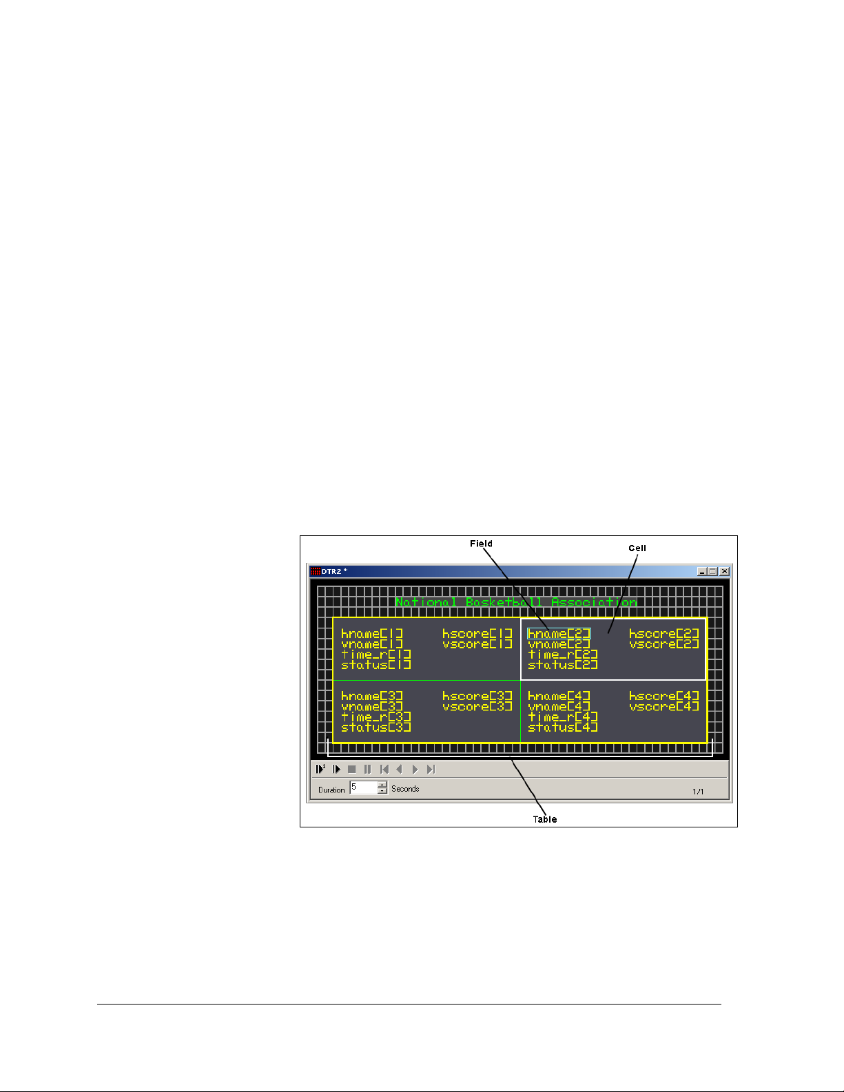
Table: Allows a variety of information to be displayed in a structured format as shown in
Figure 1.
• Field: A
portion of the
cell that
contains the
specified data
to be
displayed.
• Cell: A
quadrant of a
table set up to
contain a
certain
number of
fields.
Figure 1: Table Dialog
2 Introduction
Page 9
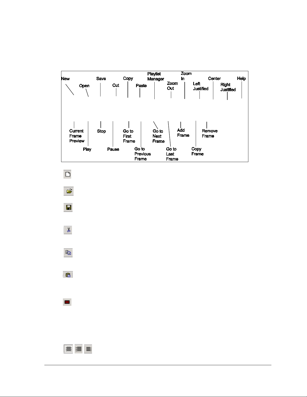
1.4 Functions of the Venus DataS t reamer Toolbar
The following items are located on the toolbar of the main screen as shown in Figure 2. This
section will explain the function of each button.
Figure 2: Venus DataStreamer Toolbar
New: Start a new message.
Open: Open a previously saved message.
Save: Save a message. If the message has not been previously saved, a window will
appear asking where to save the message and what name to give it.
Cut: Remove the selected fields from their current location in the frame of the message
and place them on the clipboard.
Copy: Copy selected fields or text from a message onto the clipboard for use in a
different message.
Paste: Place a copy of the current contents of the clipboard into the frame of a message.
Items that may be pasted include copies of other Venus DataStreamer data fields, text from
outside applications, DDE links to DDE compliant applications such as Microsoft Excel, etc.
Playlist: Defines the order and the time that messages are run on a selected display. This
is done after messages have been created and saved.
Zoom In/Zoom Out: Zoom In enlarges the contents of a frame by one step per
click. Zoom Out reduces the contents of the frame by one step per click.
Left, Center, and Right Justify: Set the position of text within a field.
Introduction 3
Page 10
About: Provides information about the software.
Preview Current Frame/ Play Message Preview/ Stop Message Preview/
Pause Message Preview: Used to preview a single frame or an entire message before sending
the message to the display.
First Frame/Previous Frame/Next Frame/ Last Frame: Used for navigation
between the frames of a message.
Add Frame: Add an empty frame to the end of the message. This only applies to
DataTracs.
Copy Frame: Insert a copy of the current frame immediately following the current
frame.
Remove Frame: Remove the current frame from a message.
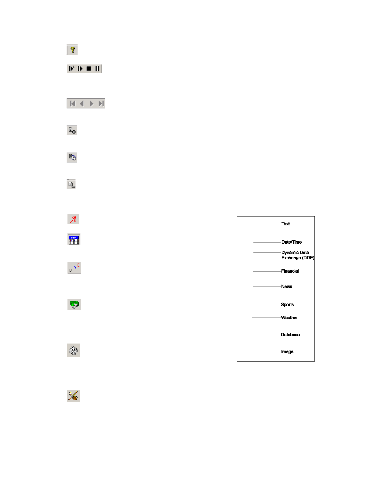
The following icons, as shown in Figure 3, are located on the left edge of the main screen.
Text: Insert text data into a message.
Date/Time: Insert new Date or Time data into a
message.
Dynamic Data Exchange (DDE): Add data gathered
from other DDE compliant applications such as Microsoft
Excel.
Financial: Insert new financial data into a message.
Information is collected from external data sources based on
set parameters. Separate data service registration and fees
may apply.
News: Insert news data into a message. The news
driver will collect information from external data sources
based on set parameters. Separate data service registration
Figure 3: Frame Type Toolbar
and fees may apply.
Sports: Insert new sports data into a message. The sports driver will collect information
from an external data source based on the set parameters. Separate data service registration
and fees may apply.
4 Introduction
Page 11

Weather: Insert new weather data into a message. The weather driver will collect data
from external data sources based on the set parameters of the field. Separate data service
registration and fees may apply.
Database: Insert new database data into a message. The database driver will collect
data from specified databases based on set parameters.
Image: Insert new image into a message.
1.5 Help Menu
The Help pull-down menu provides two options: Contents and About Venus DataStreamer.
Contents: The DataStreamer manual information is available under this heading. Double-
click the desired section and
the sub-sections will be listed.
Click on the desired subsection to go to that text.
About DataStreamer: This box
contains information about the
software, including its version,
system information, and
Daktronics contact
information as shown in
Figure 4.
Click OK or press [Enter] to
exit this dialog.
Figure 4: About DataStreamer Screen
1.6 Basic Steps to Using the Venus DataStreamer Software
This manual is arranged in the basic chronological order used to create and show information
on a DAKTicker or DataTrac display. In summary, the steps to follow are:
1. Install the Venus DataStreamer Control Software if it is not already installed on the
computer.
2. Configure the display type(s) and the communication method.
3. Configure external data sources if needed.
4. Create the message.
5. Add messages to the display playlist.
6. Schedule message entries, if desired.
7. Update the display.
This manual will walk through the steps necessary to use this display system to its full
potential.
Introduction 5
Page 12

1.7 Contacting Daktronics
If any problems or questions arise that are not discussed in this manual, contact Daktronics
using any of the following methods:
Mail: Daktronics Customer Service
PO Box 5128
201 Daktronics Drive
Brookings, SD 57006-5128
Phone: Customer Service: 800-DAKTRONICS (800-325-8766)
Fax: 605-697-4700 ATTN: Customer Service
Website: http://www.daktronics.com
6 Introduction
Page 13

Section 2: Installation
The Venus DataStreamer software must be installed to the hard drive before use. To install the
software to your computer, follow these steps.
NOTE: PRIOR to installing the Venus DataStreamer software, all USB software keys must be
REMOVED. Failure to remove the software key will result in deleting of the key. If the software is
installed without removing the USB key, a new key will have to be ordered from Daktronics
before the software will be able to run.
1. Place the Venus DataStreamer installation compact disk (CD) into the appropriate CD ROM
(presume drive D:).
2. The installation should begin automatically within a few seconds. If it does not, click the Start
button and select Run from the menu. Type “D:\SETUP” and press [Enter].
3. Follow the instructions on the screen. SETUP will copy the files necessary to run the Venus
DataStreamer software to the hard drive and create Venus DataStreamer in the Start menu.
Note: The Venus DataStreamer software installs to the C:\Program\Files\Daktronics\Venus
DataStreamer directory by default. This is the recommended location.
4. The Venus DataStreamer control software is now installed and ready to be configured for use
with the Venus DataStreamer displays.
Installation 7
Page 14

Page 15

Section 3: Configuration
After installing the Venus DataStreamer software on the computer, the individual displays must be
configured. The required steps are covered in this section. Refer to Figure 5.
Figure 5: Main Configuration Window
This section provides basic instructions and examples for configuring DAKTickers and DataTrac
displays that are controlled with the Venus DataStreamer software.
3.1 DAKTicker Display Configur at ion
Displays will need to be configured once the software is installed. To launch the
configuration window, click the File menu, and then click Configuration (File >
Configuration).
1. Click Add New Display and a pop-up window will appear asking what type of
display is being configured.
2. Click the down arrow to select the DAKTicker.
3. Click OK to move on to the next step or Cancel to void the configuration process.
Configuration 9
Page 16

4. Select the type of communication
that will be used, either "Direct
Communication" or "Remote
Communication" as shown in
Figure 6. Direct consists of a direct
serial connection from the PC.
Remote is via a TCP/IP connection
to the display.
5. Once the communication type is
selected, fill in any other necessary
information, (i.e. Com Port or IP
Address).
Figure 6: Configure Communications Dialog
6. Select the Baud Rate from the list provided. Check display documentation for the
correct baud rate to use.
7. Click Next to accept the entered information and move to the next step or click
Cancel to void the Configuration process entirely.
Note: For this example, Direct Communication is chosen.
8. Click the down arrow next to Display Height to set this according to the height of the
DAKTicker pixels as shown in Figure 7.
9. Click the down arrow next to Color
Depth to set the type of color
technology for this display. Default
setting is Tricolor.
10. Click the down arrow next to
Direction to determine if the
information will flow from left to
right or right to left. The default
setting for this is right to left.
11. Once these parameters are set, click
Next to move to the next screen.
Figure 7: Configure Display Settings
Click Cancel to close the Configure Display Parameters window.
10 Configuration
Page 17

12. Click the down arrow next to
Display Type and set whether the
DAKTicker is an indoor display or
an outdoor display as shown in
Figure 8.
Note: It is important to set this
properly as it will affect the display
speed.
13. Move the slider bar to set the
Display Speed at which information
will travel across the DAKTicker.
Daktronics recommends a speed of
90. However, this may need to be
Figure 8: Configure Display Parameters
adjusted depending on the overall
length of the DAKTicker.
Note: Click and hold the mouse button down on the slider bar to show the speed at which
the display is currently running. The speed is indicated in columns per second.
14. Click the down arrow or click
within the field to select the Number
of Displays attached to the display
network. Click the “>>>” to select
the addresses of the individual
displays that will be attached to the
network. The first display in the list
will be monitored for the current
status. Please note: All displays will
show the same information. Click
Next to move to the next screen.
15. Enter a name for the display as
Figure 9: Display Na m e Dialog
shown in Figure 9. Click Next.
16. The last screen in the Configuration
shows all the information that was
entered during configuration as
shown in Figure 10. Take time to
review this information. If something
needs to be changed, click Back to get
to the correct screen and make
changes. If everything is correct, click
Finish to save the configuration.
Figure 10: Configuration Overview
Configuration 11
Page 18

Rename a Display
Once in the configuration window, a
display can be renamed if necessary. To
rename the display, click the desired
display in the Installed Displays list and
click Rename Display. The Display Name
Settings window will appear as shown in
Figure 11. Enter the new name for the
display and click OK to save the name or
click Cancel to void the action.
Figure 11: Renaming a Display
Edit a Display
Once in the configuration window, a display’s properties can be edited. To edit a display,
click the desired display in the Installed Displays list and click Edit Display. The Configure
Display Communications window will appear. To make the necessary changes, click Next until
all changes are made and Finish appears on the last screen. Click Finish to save the changes
or click Cancel to void the changes.
Remove a Display
Once in the configuration window, a display can be removed. To remove a display, click the
desired display in the Installed Displays list and click Remove Display. The display is
instantly removed from the Installed Displays list.
3.2 Panelized DataTrac Di s play Configuration
1. Go to the File menu and click Configuration.
2. Click Add Display and a pop-up window
will appear asking what type of display is
being configured.
3. Click the down arrow to select the Panelized
DataTrac as shown in Figure 12.
4. Click OK to move to the next step or Cancel
to void the configuration process.
Figure 12: Select Display Type
12 Configuration
Page 19

5. Select the type of communication that will
be used, either "Direct Communication" or
"Remote Communication". Direct consists
of a direct serial connection from the PC.
Remote uses a TCP/IP connection to the
display as shown in Figure 13.
6. Once the communication type is selected,
fill in any other necessary information,
(i.e. Com Port or IP Address). Click Next
to accept the entered information and
move on to the next step or click Cancel to
Figure 13: Configuring Communication
void the Configuration process entirely. Note: For this example, Direct
Communication is chosen.
7. To set Display Dimensions, click the down
arrow next to each field or click in the
field to set the overall height and width of
the Panelized DataTrac as shown in
Figure 14. The Upper Left Coordinate
values are typically set to 1 for X and 1 for
Y.
8. Click the down arrow next to Color Depth
to set the type of color technology for this
display. Default setting is Tricolor.
Figure 14: Configure Display Settings
9. Once these parameters are set, click Next to move to the next screen. Click Cancel to
close the Configure window.
10. Move the slider bar to set the Display
Brightness level of the information on the
Panelized DataTrac. Daktronics
recommends a brightness of 48.
However, this may need to be adjusted
depending on different lighting
conditions. Click Next.
Note: Clicking and holding the mouse
button down on the slider bar will cause
a pop-up window to appear showing
the brightness level that the current
display is running. This number will
Figure 15: Naming a Display
change as the slider is moved.
11. Enter a name for the display as shown in Figure 15. Click Next.
Configuration 13
Page 20

12. The last screen in the Configuration
shows all the information that was
entered during configuration as
shown in Figure 16. Take time to
review this information. If something
needs to be changed, click Back to get
to the correct screen and make
changes. If everything is correct, click
Finish to save the configuration.
3.3 Data Driver Configuration
Data Drivers provide a means of accessing
and translating information from external data sources that can be shown via electronic
displays. These information sources include Financial, Weather, Sports, and News
subscriptions as well as generic DDE and Database sources. The drivers operate as a
component of the Venus DataStreamer software, connecting to the data sources and then
formatting the information to be shown. Since configurations differ by driver type, each is
explained separately in this section.
Configuring the Financial Driver
To configure the Financial driver:
1. Click File from the pull-down menu and click Configuration. The main
configuration window will appear.
2. Click the Driver Configuration tab.
3. If registered for this driver source, the box next to it is checked and the configuration
can proceed. If not currently
licensed to receive data, please
contact a Daktronics Sales
representative for more
information.
4. If registered, highlight the DTN
Financial Driver on the left, and
then click Configure Data Source.
5. Enter the configuration data as
supplied by Daktronics as shown
in Figure 17. Set the frequency
that the information should be
updated, either by using the down arrow next to the field or by clicking into the field
itself.
Figure 16: Configuration Overview for DataTrac
Figure 17: Configuring the Financial Driver
14 Configuration
Page 21

Source Tab
Note: The default values set here should only be changed if directed by Daktronics.
1. Place a checkmark in the Edit box next to
the field to be changed as shown in
Figure 18.
2. The selected address field is now active.
Click in the address field and make
necessary address changes.
3. Click Apply to complete.
Configuring the Weather Driver
To configure the Weather driver:
1. Click File from the pull-down menu and click Configuration. The main
configuration window will appear.
2. Click the Driver Configuration tab.
3. If registered for this driver source,
the box next to it is checked and the
configuration can proceed. If not
currently licensed to receive data,
please contact a Daktronics Sales
representative for more information.
4. If registered, highlight the DTN
Weather Driver on the left. Then
click Configure Data Source.
5. Enter the configuration data as
supplied by Daktronics as shown in
Figure 19.
6. Set the frequency that the information should be updated either by using the down
arrow next to the field or by clicking into the field itself.
Figure 18: Source Tab Dialog
Figure 19: Configuring the Weather Driver
Configuration 15
Page 22

Source Tab
Note: The default values set here should only be
changed if directed by Daktronics.
1. Place a checkmark in the Edit box next to
the field to be changed as shown in
Figure 20.
2. The selected address field is now active.
Click in the address field and make
necessary address changes.
3. Click Apply to complete.
Figure 20: Source Tab Dialog
Configuring the MarketWatch News Driver
Complete the following steps to configure
the MarketWatch News driver:
1. Click File from the pull-down menu
and click Configuration. The main
configuration window will appear.
2. Click the Driver Configuration tab.
3. If registered for this driver source,
the box next to it is checked and the
configuration can proceed. If not
currently licensed to receive data,
please contact a Daktronics Sales representative for more information.
4. If registered, highlight MarketWatch News on the left, and then click Configure
Data Source.
5. Enter the configuration data as supplied by Daktronics as shown in Figure 21.
6. Set the frequency that the information should be updated either by using the down
arrow next to the field or by clicking into the field itself.
Figure 21: Configuring the MarketWatch Driver
16 Configuration
Page 23

Source Tab
Note: The default values set here should only be changed if directed by Daktronics.
1. Place a checkmark in the Edit box
next to the field to be changed as
shown in Figure 22.
2. The selected address field is now
active. Click in address field and
make necessary address changes.
3. Click Apply to complete the changes.
Filtering Tab
Figure 22: Source Tab for MarketWatch
The Filter list will prevent certain words or
phrases in headlines from appearing on the display.
Example: If the word “and” is added to
the Filter list, every headline containing
the word “and” will be blocked from
showing on the display, regardless of
other content in the headline.
Click the Filtering tab to view the current
filter list. Words or phrases can be added
to the list by typing in the blank field and
then clicking Add. A word or phrase can
be removed from the list by highlighting
the phrase to be removed in the Filter List
and clicking Remove as shown in Figure
23.
Figure 23: Filtering Tab Dialog
Configuring the TSN Sports Driver
The TSN server provides sports data to the Venus DataStreamer software.
In order to receive updated schedules each day, the software must be left running
overnight. Data will be available as it is received from the TSN servers.
Complete the following steps to configure the TSN Sports driver:
Configuration Tab
1. Click File from the pull-down menu and click Configuration. The main
configuration window will appear.
Configuration 17
Page 24

2. Click the Driver Configuration tab.
3. If registered for this driver source, the
box next to it is checked and the
configuration can proceed. If not
currently licensed to receive data, please
contact a Daktronics Sales representative
for more information.
4. If registered, highlight the TSN Sport
Driver and click Configure Data Source.
The TSN Sport (XML Feed) Properties
window will appear as shown in Figure
24.
Figure 24: Configuring the TNS Sports Driver
5. Enter the Username and Password and click Apply.
6. Set the Refresh Schedule by clicking on the scroll buttons to the desired time of day.
Refresh Schedule is used to determine when the data received the previous day will be
removed from the display.
Source Tab
1. Click the Source tab and review the Address and Port Number information. If a
correction needs to be made, click the Edit boxes next to the Address and Port Number
field as shown in Figure 25. The fields will become active. Enter the correct IP
Address and Port number. Daktronics
provides this information.
2. Click Apply.
Internet tunneling is a process used to access data
from outside sources by “tunneling through” the
typical network firewalls and other protective devices
installed on private networks. Please contact your
network support staff for assistance with this.
Figure 25: Source Tab for TNS
Note: If ‘Use Internet Tunneling’ is checked, the
current internet browser settings will be used for connection to the TSN server.
• If a proxy server is used for connections to the internet, it must support and allow for
internet tunneling connections.
• If internet tunneling connections are not supported, it may be necessary to bypass the
proxy server to allow connection to the TSN Server on port 4500.
18 Configuration
Page 25

Schedules Tab
The Schedules tab allows the viewing of game
schedules for the day sorted by league.
1. Click the Schedules tab as shown in
Figure 26.
2. Click the down arrow to select the
league’s schedule to view.
Note: This is an informational tab only. It won’t
affect the information viewed on the display.
Score
The Score tab allows the choice of leagues from
which to collect scores. Specific team scores
within each league can also be selected.
1. Click the Score tab.
2. Place a check mark next to each of the
leagues to be monitored as shown in
Figure 27.
3. Click the button next to each league’s
name to select the individual teams to
be monitored.
4. Select the individual teams by
clicking on each name individually
with the mouse and clicking Select.
Or click Select All to choose all of
the teams as shown in Figure 28.
5. Repeat this process for all leagues
that are to be monitored.
Figure 26: Schedules Tab Dialog
Figure 27: Setting Score Formats
Figure 28: Selecting Teams
Configuration 19
Page 26

Standings Tab
The Standings tab allows the choice of the
leagues from which standings data will be
collected.
1. Click the check boxes next to each
desired league and click Apply to
save the settings as shown in Figure
29.
2. Click OK to close the window or
click another tab to continue
configuration.
Leaders
The Leaders tab allows the choice of league
leaders' data to be collected as shown in
Figure 30.
1. Click the check boxes for each
desired league and click Apply to
save the settings.
2. Click OK to close TSN Sport
Properties window or click the next
tab to continue configuration.
News
Figure 29: Standings Tab
Figure 30: Leaders Tab
The News tab allows the choice of sports
news data to be collected. The number of
stories to collect for each league can also be
set.
1. Click the News tab.
2. Place a check mark next to each of
the leagues to be monitored as
shown in Figure 31.
Figure 31: News Tab
3. Click the button next to each
league’s name to set the number of news stories to be retrieved.
4. Repeat this process for all leagues that are to be monitored.
20 Configuration
Page 27

5. Click OK to close the TSN Sport Properties window or click another tab to continue
configuration.
News Filter
The News Filter list allows certain words or phrases in headlines to be prevented from
appearing on the display as shown in
Figure 32.
Example: If the word “and” is added to the
Filter list, every headline containing the
word “and” will be blocked from showing
on the display, regardless of other content
in the headline.
Click News Filter to view the current filter
list. Words or phrases can be added to the
list by typing in the blank field and then
clicking Add. A word or phrase can be
removed from the list by highlighting the
phrase to be removed and clicking
Figure 32: News Filter Setup
Remove.
Click OK to accept the changes.
Odds
The Odds tab allows the choice of the
leagues for which odds data will be
collected as shown in Figure 33.
1. Click the check boxes next to each
desired league and click Apply to
save the settings.
2. Click OK to close TSN Sport
Properties window or click the next
tab to continue configuration.
Figure 33: Setting the Odds Tab
Configuration 21
Page 28

Teams
The Teams tab allows the displayed names
of teams in a specific league to be
customized as shown in Figure 34.
1. Select the desired league by
clicking on the down arrow next to
the league field.
2. Click the team name that will be
edited. The name will appear in the
update field below.
3. Click the box Update the Display
Name and make desired revisions.
4. Click Update to save the changes. Click Save to complete the Sports Driver
Configuration.
5. Click OK to close.
3.4 Database Driver Configura t ion
Figure 34: Teams Tab Settings
Following are the steps for configuring a Microsoft Access
Database. To configure other database types, please consult
the local technical support staff for instructions.
1. Click the File drop-down menu and click
Configuration. The main configuration window
will appear.
2. Click the Driver Configuration tab.
3. Highlight the Database Input driver and click
Configure Data Source. The Configured Databases
window will appear as shown in Figure 35.
Figure 35: Configured Databases
Screen
22 Configuration
Page 29

4. Click Add; the Data Links Properties window will
open as shown in Figure 36.
5. Click Microsoft OLE DB Provider for ODBC
Drivers.
6. Click Next at the bottom of the screen.
7. Select the option Use Connection String as shown
in Figure 37. Click Build and the Select Data Source
window will appear.
8. Click the Machine Data Source tab. Click New.
The Create New Data Source window will appear as
shown in Figure 38. Do not change any
information on this screen. Simply click Next to
proceed to the next step.
Figure 36: Setting DataLink
Properties
Figure 37: Connection Sharing
Properties
Figure 38: Create New Data Source Dialog
Configuration 23
Page 30

9. When the next Create New Data
Source window appears, select
Microsoft Access Driver (*mdb)
and click Next as shown in
Figure 39.
A summary window will appear
showing the data source that has
been configured. Click Finish to
complete this portion and
continue to the next step. The
ODBC Microsoft Access Setup
window will appear.
10. Enter a name for the data source
Figure 39: Driver Selection
in the Data Source Name
field. Enter a description for
the data source in the
Description field as shown
in Figure 40. This
information is required and
configuration cannot be
completed without it.
11. Click the Select button and
the Select Database window
will appear as shown in
Figure 41. Navigate in the
Directories field to the
directory where the desired
Figure 40: Naming Data Source
database is stored. Select the desired database by clicking on the appropriate name
under the Database Name field. Click OK to exit the Select Database window and click
OK again to exit the ODBC Microsoft Access Setup window.
12. Click OK to close the Select
Data Source window.
13. Click OK to close the Login
window. Add the
appropriate authentication
information.
Figure 41: Database Selection
24 Configuration
Page 31

14. The dialog should now be the Data Link
Properties window with the Connection
tab selected as shown in Figure 42. Click
the down arrow under Enter the initial
catalog to use. The available catalog will be
the same as the database just configured.
Select Allow Saving Password. Click the
database so that it shows in the field
window. Click Test Connection to verify
the connection between the data source
and Venus DataStreamer software or click
OK to close this window.
15. Enter a name for the database connection
and click OK. The name for the database
connection is now listed in the Configured
Databases window and will be available as
a data source for the Venus DataStreamer
software.
16. Close the Configured Databases window by clicking Close.
Figure 42: DataLink Properties Setup
3.5 NTP Configuration
Network Time Protocol (NTP) is an Internet standard protocol that assures accurate
synchronization of computer clock times to the millisecond in a network of computers. Based
on UTC, NTP synchronizes client workstation clocks to the U.S. Naval Observatory master
clocks in Maryland, Washington D.C., and Colorado Springs, CO. If enabled, Venus
DataStreamer will send periodic time requests to the selected server.
1. Click the File drop-down menu and click Configuration. The main configuration
window will appear.
2. Click NTP Configuration.
3. Type the NTP server in the area provided. Note: To find the correct NTP server, go to
http://tf.nist.gov/service/time-servers.html
4. If desired, check the box by Update Automatically and set the frequency that the
clock should synchronized.
5. Click Apply to make changes take effect.
Note: If the PC running Venus DataStreamer is located behind a firewall or proxy server
on the network, it may be necessary to open Port 123 in order for NTP synchronization to
occur.
If this is not possible, an internal server will need to be configured. Consult the local
network administrator for more information.
Configuration 25
 Loading...