

Page 1

Reproduction Reference
DD1740664 – P1335, P1343, P1408
Service and Maintenance Manual
1) This page is for reproduction reference only and will not be included in the manual.
2) Copy this manual on front and back pages on 8 ½ x 11" paper.
Note: The first page (cover page) uses the front of the page (blank on back). Section heading
pages always start on a new page; they never start on the back of another page.
3) Insert all supplementary material as listed in Appendix A.
4) Insert SL-02374 in Appendix B.
5) Use a blue window cover and a blue back.
®
Digital Billboard
Valo
6) Punch all pages, window cover, and back cover, along the left edge and bind with a binder.
7) Direct questions and suggestions to Engineering Secretarial.
Page 2

Page 3

Valo
Service and Maintenance Manual
®
Digital Billboard
DD1740664 Rev 1 – 25 October 2010
201 Daktronics Dr. PO Box 5128 Brookings SD, 57006
Tel 866-343-3122 Fax 605-697-4700
www.daktronics.com
Page 4

Page 5

DD1740664
Project/Contract 1335, 1343, 1408
Rev 1 – 25 October 2010
DAKTRONICS, INC.
Copyright © 2010
All rights reserved. While every precaution has been taken in the preparation of this manual, the p ublisher
assumes no responsibility for errors or omissions. No part of this book covered by the copyrights hereon may be
reproduced or copied in any form or by any means – graphic, electron ic, or mechanical, including photocopying,
taping, or information storage and retrieval systems – without written permission of the publisher.
Valo®, V-Link® and Venus® are registered trademarks of Daktronics, Inc.
™
, CaiLube™, Mate-n-Lok™, and are trademarks of their respective companies.
DeoxIT
Page 6

Page 7

Table of Contents
Section 1: Introduction ................................................................................................................. 1
1.1 About This Manual ................................................................................................................. 1
Section 2: Display Identification ................................................................................................. 3
2.1 1000 Series Display ................................................................................................................. 3
2.2 2000 Series Display ................................................................................................................. 3
2.3 3000 Series Display ................................................................................................................. 3
Section 3: Display Troubleshooting ........................................................................................... 5
3.1 Troubleshooting ...................................................................................................................... 5
1000 Series Display Troubleshooting ............................................................................ 5
2000 and 3000 Series Display Troubleshooting ........................................................... 7
Section 4: Removing Modules from the Display ....................................................................... 9
4.1 Front Access ............................................................................................................................. 9
4.2 Rear Access ............................................................................................................................ 10
16 OT Module Removal ................................................................................................ 11
20 MT and 23 MT Module Removal ............................................................................ 13
Section 5: Replacing Display Components ............................................................................. 17
5.1 1000 Series Specific Procedures ........................................................................................... 17
Note on Removing Modules ........................................................................................ 17
Fine Mesh Screen ........................................................................................................... 17
Metal Frame Filter .......................................................................................................... 17
Optional Thermostat Addition to Digital Billboard Fan Filter Displays ................ 17
Reattaching Borders....................................................................................................... 18
Module Gears ................................................................................................................. 18
Legacy Cat-5 Cables ...................................................................................................... 19
5.2 2000 and 3000 Series Specific Procedures .......................................................................... 20
Note on Removing Modules ........................................................................................ 20
Replacing a Mobotix Webcam with a Panasonic Webcam ...................................... 20
Multi-line Controllers (MLC) ....................................................................................... 22
Power Supplies ............................................................................................................... 22
Filters ............................................................................................................................... 23
Photo/Temp Cell ........................................................................................................... 23
Section 6: Routine Maintenance ............................................................................................... 25
6.1 Inspecting a Display ............................................................................................................. 25
Table of Contents
i
Page 8

6.2 Restarting a Display .............................................................................................................. 25
6.3 Applying Silicone to Display Back Sheets ......................................................................... 26
6.4 Cleaning a Webcam Lens ..................................................................................................... 26
6.5 Applying a Gasket to the Spare Parts Box ......................................................................... 26
6.6 Fan Operation ........................................................................................................................ 27
6.7 Control Cabinet Heating Inspection ................................................................................... 27
6.8 Structural Inspection ............................................................................................................. 28
6.9 Spare Parts .............................................................................................................................. 28
6.10 Service Call ............................................................................................................................. 29
Service Instructions ........................................................................................................ 29
6.11 Annual Maintenance Checks ............................................................................................... 31
Service Instructions ........................................................................................................ 31
6.12 Cleaning a Display Face ....................................................................................................... 35
Wet Cleaning Instructions ............................................................................................ 35
Dry Cleaning Instructions ............................................................................................. 35
Section 7: Power and Signal Testing ........................................................................................ 37
7.1 Testing the Display Ground ................................................................................................ 37
Testing with a Ground Meter ....................................................................................... 37
Testing with a Multimeter ............................................................................................ 37
Glossary .................................................................................................................................... 39
Appendix A: Supplementary Material ......................................................................................... A-1
Appendix B: Daktronics Warranty and Limitation of Liability .................................................. B-1
ii
Table of Contents
Page 9
Section 1: Introduction
This manual provides service and maintenance information for Valo® digital billboards. To ensure
optimal display life, take time to read and understand the information in this manual.
1.1 About This Manual
This manual is divided into seven sections:
• Introduction: Explains basic information needed to use this manual.
• Display Identification: Explains differences between series displays.
• Display Troubleshooting: Explains basic troubleshooting steps.
• Removing Modules from the Display: Explains the various ways of removing
modules from a display.
• Replacing Display Components: Explains how to replace display components.
• Routine Maintenance: Explains recommended guidelines for service calls and
annual maintenance checks.
• Power and Signal Testing: Explains how to test power and signal.
At the end of this manual are a glossary and two appendices:
• Glossary: Defines various terms.
• Appendix A: Supplementary Material: Contains retrofit kit drawings, checklists,
technical service bulletins, and quick guides referenced throughout the manual.
• Appendix B: Daktronics Warranty and Limitation Liability: Provides information
on warranty and liability.
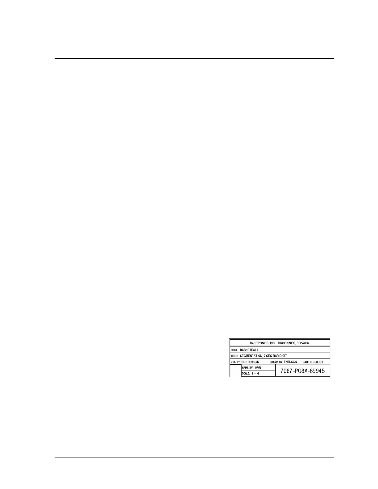
Figure 1 illustrates a Daktronics drawing label. The
drawing number is located in the lower-right corner
of a drawing. This manual refers to drawings by
listing the last set of digits and the letter preceding
them. In the example, the drawing would be
referred to as Drawing A-69945.
Figure 1: Daktronics Drawing Label
All references to drawing numbers, appendices, figures, or other manuals are presented in
bold typeface, as shown above.
Introduction 1
Page 10

Page 11
Section 2: Display Identification
Daktronics has shipped three major series of Valo® digital billboards. The 1000 series shipped from
2005 to 2008. The 2000 series shipped from October 2007 to November 2009. The 3000 series started
shipping on December 2009. There are differences in the design and components in each series, and it
is important to be able to identify the differences as service and maintenance requirements vary by
series.
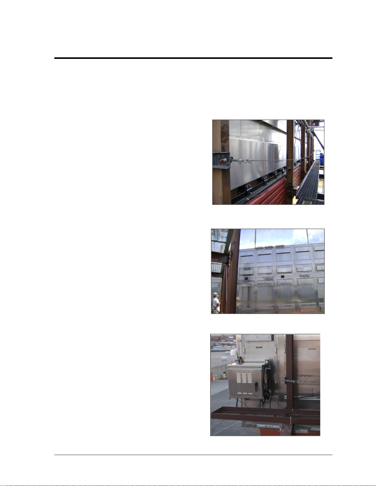
2.1 1000 Series Display
There were many variations within the 1000
series displays; however, the cabinet design
remained consistent. The 1000 series displays
are front access only. This is the easiest way to
identify the series. Refer to Figure 2.
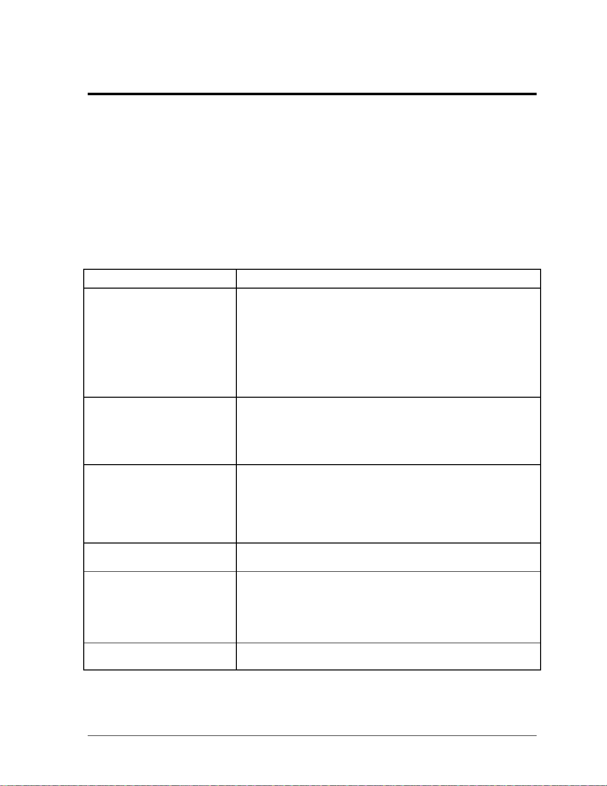
2.2 2000 Series Display
The 2000 series displays have minor variations
in the series. The cabinet and technologies
remain similar. The 2000 series displays can be
accessed from the rear as well as the front. To
identify these displays, look for rear access
doors on the back of the display. Refer to
Figure 3.
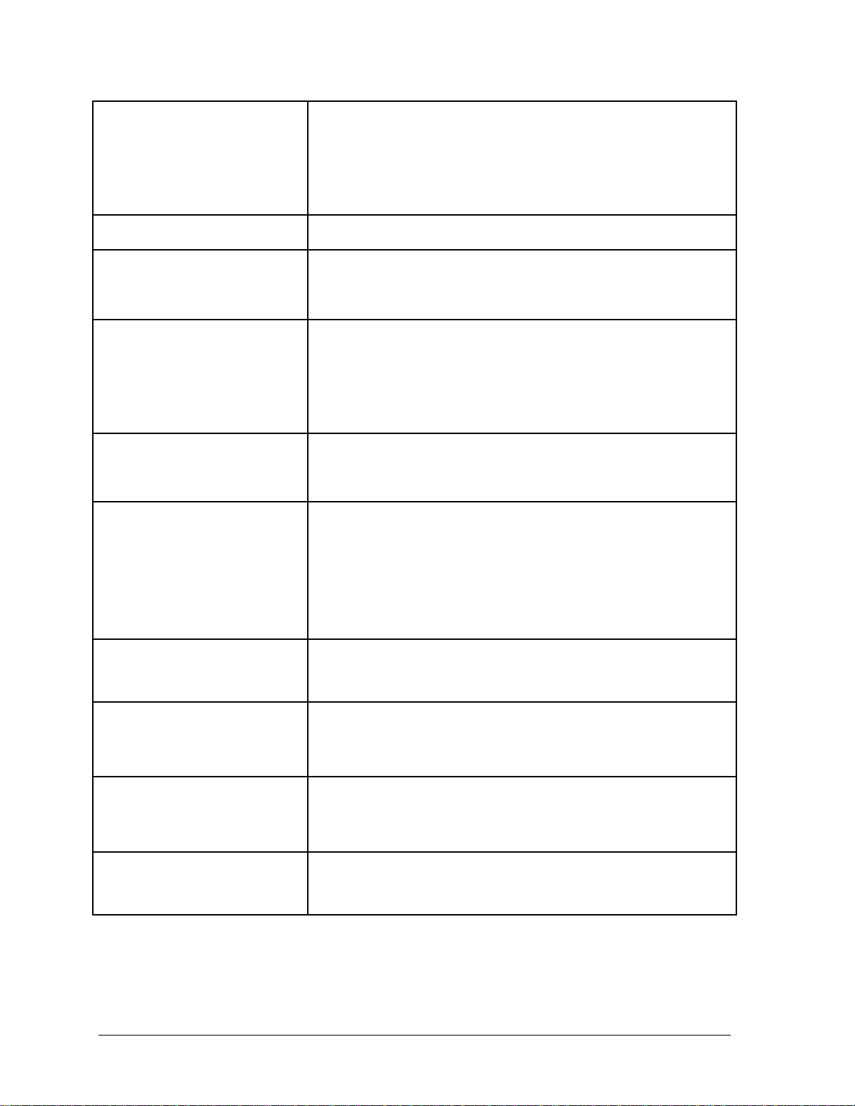
2.3 3000 Series Display
The 3000 series rear-mounted remote
enclosure is standard for all shipments. The
3000 series displays can be accessed from the
rear as well as the front. To identify these
displays, look for rear access doors on the back
of the display. Refer to Figure 4.
Figure 2: 1000 Series
Figure 3: 2000 Series
Display Identification
Figure 4: 3000 Series
3
Page 12

Page 13
Section 3: Display Troubleshooting
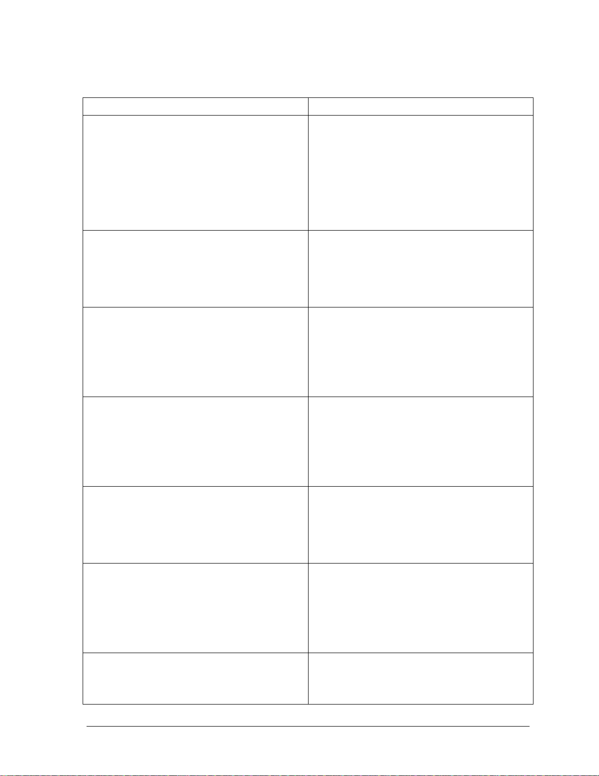
The following table lists some problems that may occur while operating a display. The left column
contains a list of display problems. The right column contains a list of troubleshooting steps to help
resolve the issue. While this table does not cover all possible problems that may occur, it does cover
those that may occur most often. The first table covers troubleshooting issues for the 1000 series
display, and the second table covers troubleshooting issues for the 2000 and 3000 series displays.
3.1 Troubleshooting
1000 Series Display Troubleshooting
1000 Series Display Problem Troubleshooting Steps
Entire display is blank • Check that the display is receiving power and that all breakers are on.
• Verify power supply LEDs are on when power is applied to display
(data distributor, multi-line controller, control cabinet, etc).
• Check the status of the data distributor card to make sure it is not
blank (signal locked, configured, etc).
• Ensure fiber-optic signal cable is connected to the data distributor
and the signal is locked.
• Check that the V-Link
Blank section of display • Ensure the power status LEDs on the modules, power supplies, and
multi-line controllers in the blank section are all on.
• Verify all RJ45 connections to the multi-line controllers are secure.
Change the connections with one another to test.
• Make sure all ribbon cable connections to the modules are secure.
Blank 5 high × 4 wide module
section
Blank 5 high × 2 wide module
section
Blank row of modules • Check the ribbon cable connections between the modules and multi-
• Check the power status LED on the multi-line controllers in the blank
section.
• Make sure the status indicator LCD on the multi-line controller is
changing.
• Verify all RJ45 connections to the multi-line controllers in the blank
section are secure. Change the connections with one another to test.
• Check the power supply to the affected modules.
line controller in the blank section. From the front of the display,
check the connection of the left-most module first.
• Ensure the modules are receiving signal and power. Signal will not
pass through a module that does not receive signal and power.
®
content output is on (not blank).
Blank 1 high x 10 wide module
section
Display Troubleshooting
• Check the power supply to the modules.
5
Page 14
Blank module • Check the power status LEDs on all power supplies connected to the
module. If a power indicator LED is off, check to make sure the fuse
on the power supply output is intact and all power connections are
securely fastened.
• Check the ribbon cable input to the module and the output from the
previous module or multi-line controller.
Blank half-module • Check the ribbon cable of the module to the left of the blank module.
Garbled half-module • Check the ribbon cable connections between modules and the multi-
line controller in the garbled section. From the front of the display,
check the connection of the left-most module first.
Garbled module • Check the ribbon cable input to the module and the output from the
module to its multi-line controller.
• Ensure all connections on the module power supplies are tight. A
garbled module can be an indicator of power supply failure. A module
with no power will be blank and will not pass signal to the next
module.
Garbled row • Check the ribbon cable connections between the modules and the
multi-line controller in the garbled section. From the front of the
display, check the connection of the left-most module first.
Garbled or uncontrollable display • Check the d ata distributor receiver board status LEDs to make sure it
is receiving power.
• Verify the V-Link configuration.
• Ensure the fiber-optic signal cable is connected to the data distributor
and the signal is locked and receiving configuration.
• Verify all RJ45 connections and ribbon cables are connected to the
correct locations.
Section of display is lighter than
rest
Discolored 1 high × 4 wide module
section
Discolored module • Check all ribbon cables and make sure all power connections are
Hanging module • Check the module to see if the module will reinsert and lock into the
• Test RJ45 cable input for the multi-line controller.
• Test the power supply for the multi-line controller.
• Replace the multi-line controller.
• Check that RJ45 and power connections to the multi-line controllers
are securely fastened.
• Verify that calibration frame being used is correct, and re-send if
required.
securely fastened.
• Verify the correct calibration frame is being used.
display. If it does not lock to the display, replace it with a spare
module and send the old module to Daktronics for repair.
6
Display Troubleshooting
Page 15
2000 and 3000 Series Display Troubleshooting
2000 and 3000 Series Display Problem Troubleshooting Steps
Entire display is blank • Check that the display is receiving power and all
breakers are turned on. When power is applied to
the display, power supply LEDs should turn on.
• Check the data distributor LCD status to make
sure the input signal is locked and the output is
not blank.
• Make sure the fiber-optic signal cable connects to
the data distributor. The input signal should be
locked.
Section of display is blank • Make sure the power status LEDs on the
modules, power supplies, and in the blank section
are all on.
• Make sure fiber connections to the multi-line
controllers in the blank section are secure.
Change the connections with one another to test.
16-48 high section of display is blank • Check the power status LED on the multi-line
controller in the blank section.
• Verify the status indicator digit on the multi-line
controller.
• Make sure fiber connections to the multi-line
controllers in the blank section are secure.
Change the connections with one another to test.
16 high section of display is blank • Check the ribbon cable connections between
modules and the multi-line controller in the blank
section. From the front of the display, check the
connection of the left-most module first.
• Make sure that modules are receiving signal and
power. Signal will not pass through a module that
does not receive signal and power.
Module is blank • Check the power status LEDs on all power
supplies connected to the module. If a power
indicator LED is off, ensure the fuse on the power
supply output is intact.
• Check the ribbon cable input to the module and
the output from the previous module.
Entire display is garbled or uncontrollable • Check the data distributor receiver board status
LEDs to make sure the data distributor is receiving
power.
• Ensure the fiber-optic signal cable is connected to
the data distributor. The input signal should be
locked. If the input signal is not locked, check the
fiber connections.
8 high section of the display is garbled • Check the ribbon cable connections between
modules in the garbled section. From the front of
the display, check the connection of the left-most
module first.
Display Troubleshooting
7
Page 16

Single module is garbled • Check the ribbon cable input to the module and
the output to the previous module.
• Make sure all connections on the module power
supplies are tight. A garbled module could indicate
power supply failure. A module with no power is
blank and does not pass signal to the next
module.
8
Display Troubleshooting
Page 17

Section 4: Removing Modules from the Display
After removing a module from the display, take a moment to inspect the weather stripping on the
rear of the module. On a properly secured module, the weather stripping prevents moisture from
seeping into the display. Deteriorated weather stripping may lead to water-related display damage.
Required tools:
• Phillips head screw driver or
1
/8" T-handle Allen wrench
•
• Allen wrench set
• Safety lanyard
4.1 Front Access
Most display components are rear accessible; occasionally, you may need to remove a display
component from the front.
Note: 1000 series displays are front access only.
To remove a module from the front of the display:
1. Disconnect display power.
2. With a
the top and bottom latch releases
approximately
clockwise. Refer to Figure 5 for the
approximate location of the holes.
1
/8" hex head driver, turn
5
/16" nut driver
1
/2 turn counter-
3. Pull the module from the display
just far enough to reach around to
the back of the module. Attach one
end of the safety lanyard to a
lanyard attachment ring on the
module. Attach the other end of the
safety lanyard to a nearby upright
or wire rod. Use the safety lanyard
in this way to prevent module
damage.
4. Disconnect the power and signal cables from the rear of the module.
5. Reverse Steps 1-4 to install a module in the display.
Removing Modules from the Display
Figure 5: Module Face
9
Page 18

6. Gently pull the module to verify that it is properly seated.
4.2 Rear Access
Note: Depending on display configuration, you may need to remove a power supply and/or
multi-line controller in order to access a module from the rear. These situations are covered
throughout Section 4.
Note: If the access door has fans connected to it, disconnect display power before pulling the
door away.
1. Lift the access door straight up.
2. Pull the bottom of the display door
away from the back of the display.
3. Carefully place the access door out of
the way.
4. Disconnect the power and signal
cables from the rear of the module.
5. Attach one end of the safety lanyard to
a lanyard attachment ring on the
module. Attach the other end of the
safety lanyard to a nearby upright or
wire rod. Use the safety lanyard in this
way to prevent module damage.
6. Disengage the upper and lower
module latch release with a
1
/8" Allen
Figure 6: Module Rear
wrench and turn the release
approximately
1
/2 turn clockwise. Refer to Figure 6.
7. Maintain a firm grip on the module, push it through the front of the display, and
rotate the module in a manner that allows it to pull back through the frame opening.
8. Reverse the above steps to reinstall a module.
10
Removing Modules from the Display
Page 19

16 OT Module Removal
16 OT modules are rectangular. It is easiest to remove the module by pulling it lengthwise
through the display face.
Unobstructed 16 OT Module Removal
1. Disconnect power and signal
cables. Refer to Figure 7.
2. Attach one end of the safety
lanyard to a lanyard
attachment ring on the
module. Attach the other end
of the safety lanyard to a
nearby upright or wire rod.
Use the safety lanyard in this
way to prevent module
damage.
Figure 7: Module Connections
3. Use a T-handle Allen wrench
to disengage module latches.
4. Carefully push the module
out of the display face. Refer
to Figure 8.
Note: Sometimes it may be
necessary to remove the
module beside, above, or
below in order to access the
target module.
5. Pivot the module to pull it
through the back of the
display.
6. Reverse Steps 1-5 to reinstall the module.
Figure 8: Pulling a Module through the rear of the Display
Removing a 16 OT Module behind a Power Supply
1. Remove the
5
/16" TEK screw that holds the power supply bracket in place.
2. Pull the finger tab to disengage the power supply. Refer to Figure 12 for an illustration of
a power supply.
3. Lift the module power supply off the hook mount.
4. Gently set the power supply assembly down.
Removing Modules from the Display
11
Page 20

5. Disconnect power and signal cables
from the module. Refer to Figure 7.
6. Attach one end of the safety lanyard
to a lanyard attachment ring on the
module. Attach the other end of the
safety lanyard to a nearby upright or
wire rod. Use the safety lanyard in
this way to prevent module damage.
7. Use a T-handle Allen wrench to
disengage module latches.
8. Carefully push the module out of the
display face.
9. Pivot the module to pull it through the back of the display.
10. Reverse Steps 1-8 to reinstall the module.
Figure 9: Removing Term Panel Support Screws
Removing a 16 OT Module Behind a Multi-Line Controller
1. Pull the finger tab to disengage the multi-line controller.
2. Lift the multi-line controller off the hook mount.
3. Gently set the multi-line controller assembly down.
4. Disconnect the module power and signal cables. Refer to Figure 7.
5. Attach one end of the safety lanyard to a lanyard attachment ring on the module. Attach
the other end of the safety lanyard to a nearby upright or wire rod. Use the safety
lanyard in this way to prevent module damage.
6. Use a T-handle Allen wrench to disengage the module latches.
7. Carefully push the module out of the display face.
8. Pivot the module to pull it through the back of the display. Refer to Figure 8.
9. Reverse Steps 1-8 to reinstall the module.
Removing a 16 OT Module behind a Termination Panel
1. Remove the two support screws from the top of the termination panel.
2. Pull the finger tab to disengage the termination panel.
3. Lift the termination panel off the hook mount.
4. Gently set the termination panel assembly down.
12
Removing Modules from the Display
Page 21

5. Disconnect the module power and signal cables. Refer to Figure 7.
6. Attach one end of the safety lanyard to a lanyard attachment ring on the module. Attach
the other end of the safety lanyard to a nearby upright or wire rod. Use the safety
lanyard in this way to prevent module damage.
7. Use a T-handle Allen wrench to disengage module latches.
8. Carefully push the module out of the display face.
9. Pivot the module to pull it through the back of the display. Refer to Figure 8.
10. Reverse Steps 1-9 to reinstall the module.
20 MT and 23 MT Module Removal
23 and 23 MT modules are square. Typically, modules should pull through the display face
with the same ease no matter the direction.
Removing the Rear Access Display Door
1. Determine which door needs to be removed to best access the module.
2. Lift the access door straight up.
3. Pull the bottom of the display door away from the back of the display.
4. Carefully place the access door out of the way.
Unobstructed 20 MT or 23 MT Module Removal
1. Disconnect power and signal cables.
2. Attach one end of the safety lanyard to a lanyard attachment ring on the module. Attach
the other end of the safety lanyard to a nearby upright or wire rod. Use the safety
lanyard in this way to prevent module damage.
3. Use a T-handle Allen wrench to disengage module latches.
4. Carefully push the module out of the display face.
5. Pivot the module to pull it through the back of the display.
Note: Sometimes it may be necessary to remove the module beside, above, or below in
order to access the target module.
Removing a 20 MT or 23 MT Module behind a Power Supply
1. Remove the
2. Pull the finger tab to disengage the power supply. Refer to Figure 12 for an illustration of
the power supply.
Removing Modules from the Display
5
/16" TEK screw that holds the power supply bracket in place.
13
Page 22

3. Lift the module power supply off the hook mount.
4. Gently set the power supply assembly down.
5. Disconnect power and signal cables.
6. Attach one end of the safety lanyard to a lanyard attachment ring on the module. Attach
the other end of the safety lanyard to a nearby upright or wire rod. Use the safety
lanyard in this way to prevent module damage.
7. Use a T-handle Allen wrench to disengage module latches.
8. Carefully push the module out of the display face.
9. Pivot the module to pull it through the back of the display.
10. Reverse Steps 1-8 to reinstall the module.
Removing a 20 MT or 23 MT Module Behind a Multi-Line Controller
1. Pull the finger tab to disengage the multi-line controller.
2. Lift the multi-line controller off the hook mount.
3. Gently set the multi-line controller assembly down.
4. Disconnect the module power and signal cables. Refer to Figure 7.
5. Attach one end of the safety lanyard to a lanyard attachment ring on the module. Attach
the other end of the safety lanyard to a nearby upright or wire rod. Use the safety
lanyard in this way to prevent module damage.
6. Use a T-handle Allen wrench to disengage module latches.
7. Carefully push the module out of the display face.
8. Pivot the module to pull it through the back of the display.
9. Reverse Steps 1-8 to reinstall the module.
Removing a 20 MT or 23 MT Module behind a Termination Panel
1. Remove the two support screws from the top of the termination panel.
2. Pull the finger tab to disengage the termination panel.
3. Lift the termination panel off the hook mount.
4. Gently set the termination panel assembly down.
5. Disconnect the module power and signal cables. Refer to Figure 7.
14
Removing Modules from the Display
Page 23

6. Attach one end of the safety lanyard to a lanyard attachment ring on the module. Attach
the other end of the safety lanyard to a nearby upright or wire rod. Use the safety
lanyard in this way to prevent module damage.
7. Use a T-handle Allen wrench to disengage module latches.
8. Carefully push the module out of the display face.
9. Pivot the module to pull it through the back of the display.
10. Reverse Steps 1-9 to reinstall the module.
Removing Modules from the Display
15
Page 24

Page 25

Section 5: Replacing Display Components
5.1 1000 Series Specific Procedures
Note on Removing Modules
The 1000 series displays are front access only. Refer to Section 4: for instructions on
removing a module from the front of the display.
Fine Mesh Screen
1. Cut out the existing fine mesh screen with a utility knife.
2. Align the rivet clearance holes on the grill cover (OM-353962) over the existing rivet
heads.
3. Fasten the grill cover into place with #10 TEK screws.
Note: TEK screws go into the small holes. There are two holes on each end of the grill
and two in the middle section.
Metal Frame Filter
Before May 2007, the 1000 series displays used metal frame filters. Release five of the 1000
series introduced the green filter, which is now a standard part on displays after May 2007.
The green filter retrofit kit (0A-1413-3900) was introduced in April 2007 and should be used
during routine filter service on 1000 series displays that still have metal frame filters.
To replace the metal frame filter, follow the steps below.
1. Remove the metal frame filter by lifting up and pulling out from the bottom of the
filter.
2. Put the green filter in the filter holders.
3. Put the end of the filter bracket in the corner of the bottom holder, in between the
filter and the outside flange of the bottom holder.
4. Rotate toward the center of the filter to get under and in front of the top holder.
5. Rotate the filter bracket up into a vertical position. Be sure not to rotate too far, or the
channel will slip out.
Optional Thermostat Addition to Digital Billboard Fan Filter Displays
Daktronics recommends adding the thermostat to all 1000 series fan filter displays. Doing so
may prolong fan life and reduce operation costs.
Use Thermostat Addition Kit 0A-1413-3050.
To install a thermostat, follow the steps below.
Replacing Display Components 17
Page 26

1. Turn off the breakers for the display fans in each display section. Refer to the block
diagram and layout, and component drawings to determine breaker location.
2. Use the layout, component drawing to locate the first fan in each display section.
3. Remove the module that is in front of the first fan in each display section.
4. Disconnect the power quick-connect from the breaker to the first fan.
5. Plug the thermostat’s power quick-connect into the breaker quick-connect and the
fan quick-connect.
6. Using TEK screws, attach the thermostat to a display upright. Only screw through
the mounting bracket.
7. Set the thermostat to 85° F.
8. Turn the fan breakers on.
9. Repeat Steps 1-8 for each display section.
Reattaching Borders
On some 1000 series digital billboard displays, the border pieces may come loose.
Required tools:
• Cordless drill
1
/4" Tapping screws
•
5
/16" Drill bit
•
3
/8" Driver
•
To reattach a border, follow the steps below.
1. Lift the bottom border tight against the bottom cabinet perimeter.
5
2. Drill a
mounted. Drill one pilot hole in the front and one in the rear. This will ensure that
the self-tapping screws will pull the extrusion tight.
/16" pilot hole in the first extrusion where the self-tapping screws are to be
3. Install a
1
/4" self-tapping screw in the pilot holes.
Module Gears
1. Remove the module from the display and place it face
down on a flat, dry surface.
2. Completely extend the gear arms to relieve pressure on
Figure 10: Module Gear
18
Replacing Display Components
Page 27

the latch assembly.
3. Lift one side of the gear housing.
4. Place a flat head screwdriver into the middle pry slot.
5. Firmly pry with the handle of the screwdriver until gear housing comes loose.
6. Repeat Step 4 and Step 5 on the other side of the gear housing.
7. Lift the latch arms so they are no longer engaged with the module gear.
8. Lift the module gear out of the module housing.
9. Replace the existing module gear with a replacement module gear.
10. Press the latch arms down until they engage with the module gear teeth.
11. Ensure both clasps are in all the way or out all the way before replacing the module gear
housing.
12. Place the gear housing over the module gear and latch arm assembly.
13. Place a large nut driver over the gear plug.
14. Strike the top of the nut drive with a hand to snap the gear housing into place.
15. Test the latch assembly to ensure it functions properly.
Legacy Cat-5 Cables
There have been numerous perceived failures of Cat-5 in the field. Cat-5 cables connected to
the DD, MLC, and / or as a MLC to MLC link. Failures are visual and diagnostic.
Required tools:
• Soft bristle brush
• CRC Contact Cleaner
• CRC Di-Electrical Grease
• Module wrench
• Wire cutters
Follow these steps to determine the root cause:
1. Replace the MLC or DD where the problem starts. The DD could have a bad output
or the MLC could have a bad input. Use the diagnostic codes/lights on the MLC or
DD to troubleshoot the issue.
Replacing Display Components 19
Page 28

2. If there is still a problem, replace the MLC before the problem MLC. This will verify
there is not a bad output on that MLC.
3. If the problem persists, inspect the cable link. Cut and remove the cable ties, as they
may be too tight.
4. Inspect the RJ45 ends for poor crimping/latching or corrosion. If possible, use an
Ethernet cable tester.
5. Inspect the RJ45 ends and CaiLube for dirt that would prevent the pins from making
contact. If dirt is found:
a. Power down the equipment for cleaning.
b. Clean RJ45 ends with CRC contact cleaner and a soft bristle brush.
c. Clean inside of the jacks on the MLC and/or DD with contact cleaner.
d. Apply CRC electrical grease to the jacks on the MLC and/or DD and the ends of
the RJ45 cable.
6. If the issue persists, replace the Cat-5 cable. If the cable fixes the issues, send the cable
with a parts return tag that describes the issue and display location to:
Daktronics Inc.
ATTN: Billboard Electrical Engineers
201 Daktronics Dr. PO Box 5128
Brookings, SD 57006
5.2 2000 and 3000 Series Specific Procedures
Note on Removing Modules
Refer to Section 4: for removing modules from the display.
Replacing a Mobotix Webcam with a Panasonic Webcam
Required tools:
• Mobotix to Panasonic retrofit kit (0A-1413-3013)
• Drill
1
/2" Drill bit
•
• Wire cutters
5
/16" and/or 1/4" Nut driver bit
•
• Socket set
20
Replacing Display Components
Page 29

• Various wrenches
• UV Rated Cable Ties
In most instances, a bucket truck is required to replace a webcam. To replace a webcam:
1. Locate the webcam signal connections on the display.
2. Remove the webcam power cable from the termination plate.
3. Remove the Ethernet cable from the termination plate.
1
4. Drill a
5. Attach the BNC coupler to the display.
6. Remove the connection for the webcam power.
/2" hole for the new BNC coupler near the existing webcam signal cables.
7. Replace the webcam power with the two-pin power connector.
8. Locate a half depth vertical location to mount the video server.
9. Hang the mounting plate on the half depth vertical with TEK screws.
10. Route the coaxial cable from the video server to the termination plate.
11. Connect Cable Input 1 on the video server to the new BNC coupler.
12. Connect the power cable to the adapter on the video server plate.
13. Connect the five-pin mate and lock end to the available five-pin jack on a power
supply.
14. Remove the Cat-5e cable from the jack within the display cabinet on the signal
termination plate.
15. Route and connect the Ethernet cable to the Ethernet input on the video server.
16. Locate and replace the existing transformer with the transformer located in the kit.
17. Reconnect the primary power to the transformer.
18. Route and connect the wire on the secondary side to the two-pin power connection.
19. Remove the old camera and existing camera cables.
20. Mount the Panasonic camera to the existing webcam arm.
21. Route the power and coaxial cables along the back of the display.
22. Connect the new power cable to the two-pin connector.
Replacing Display Components 21
Page 30

23. Connect the coaxial signal cable to the new BNC coupler.
24. Call Daktronics NOC at 1-877-DAK-HELP to verify that the camera is working and
focused.
Multi-line Controllers (MLC)
To remove a MLC from the display:
1. Access the interior of the display.
2. Disconnect all power and signal connectors from the
MLC.
3. Pull the finger tab and lift the MLC assembly. Refer to
Figure 11.
4. Remove the MLC assembly from the display cabinet.
5. Reverse Steps 1-4 to replace the MLC.
Power Supplies
To remove a power supply from the display:
1. Access the interior of the display. Refer to Section 5.2
for information on front and rear access.
2. Disconnect all power and signal connectors from the
power supply.
3. Remove the
place.
4. Pull the finger tab and lift the power supply assembly.
Refer to Figure 12.
5. Remove the power supply assembly from the display
cabinet.
6. Reverse Steps 1-4 to replace the power supply.
5
/16" TEK screw holding the bracket in
Figure 11: Multi-Line Controller
Figure 12: Power Supply
22
Replacing Display Components
Page 31

Filters
Filters should be checked yearly, except for sites that have been designated to be checked
every six months.
To replace a filter in the display:
1. Depress the filter release.
Refer to Figure 13.
2. Lower the filter door.
3. Remove the filter.
4. Reverse the above steps to
replace a filter.
Photo/Temp Cell
Figure 13: Filter Hood
To remove a malfunctioning photocell:
1. Unplug the photocell cable from the back of the display.
2. Cut any cable ties that are holding the photocell cable in place.
3. Unscrew the TEK screws that hold the old photocell in place.
4. Using TEK screws, reattach the new photocell in the same location as the old
photocell.
Note: If you are unable to use the same holes, fill the old holes with silicone to
prevent water intrusion.
5. Route the photocell cable along the back of the display.
6. Plug the photocell cable to the photocell connect in the back of the display.
Replacing Display Components
23
Page 32

Page 33

Section 6: Routine Maintenance
6.1 Inspecting a Display
When performing maintenance on a display, check for the following items:
• Inspect for modules protruding from the display face. If a module is protruding from
the display, press the module in and tighten the module according to the steps in
Section 5.1. If the module will still not latch, the latch may need replacement.
• Inspect for dirty filters in the display and the control enclosure. Refer to Section 5:
for filter replacement steps.
• Inspect for water in the display. If water is found, attempt to locate the source of
water intrusion.
• Ensure the cooling system and fans are working properly.
• For 1000 series displays, ensure the display border is secure. Refer to Section 5.1 for
steps on reattaching loose borders.
• Inspect the back sheets to ensure the silicone is in good condition and is sealing
properly. Refer to Section 6.3 for steps on reapplying silicone to the back sheets.
• Ensure there is not standing water in the spare parts box.
• Ensure the gasket is on the spare parts box. Refer to Section 6.6 for the steps to
reapply the gasket to the spare parts box.
• Call the NOC at 1-877-325-4357 if any of the issues are found.
6.2 Restarting a Display
Occasionally, it may be necessary to restart a display. To restart a display:
1. Shut down all control equipment in the remote enclosure.
2. Turn off the Uninterruptible Power Supply (UPS). Not turning off the UPS will delay
sign restart.
3. Turn off all breakers in the main distribution panel inside the display. Refer to the
display-specific system riser to locate the distribution panel. Typically, there is one
breaker panel per display section.
4. Turn off site power.
5. Turn on site power.
6. Turn on all breakers in the main distribution panel inside the display.
Routine Maintenance 25
Page 34

7. Restart the UPS.
8. Restart all of the control equipment in the remote enclosure.
6.3 Applying Silicone to Display Back Sheets
1. Before applying silicone to display back sheets, remove the old silicone in the area that
needs new silicone.
2. Use a clean cloth and water to clean the silicone path to remove and dirt, dust, and debris
from the path.
3. Allow the area to dry completely.
4. Evenly apply silicone over the area that needs silicone. Ensure all gaps are filled.
6.4 Cleaning a Webcam Lens
If a bucket truck is on site or the display has a retractable webcam arm, clean the camera lens
on every visit. To clean a webcam lens:
1. Carefully clean the webcam lens with a lens-cleaning wipe or with a clean rag and a
glass cleaner.
Note: If you think the lens may be out of focus after the cleaning, call 1-877-325-4357
and have the NOC ensure the webcam is focused and the image is clear.
6.5 Applying a Gasket to the Spare Parts Box
There should be a gasket around the lid lip. If there is not a gasket on the spare parts box:
1. Locate the gasket. Typically, it is stored in the spare parts box. If you cannot locate
the gasket, call customer service to order a gasket.
2. Clean the gasket lip with a clean, damp cloth.
3. Allow the lip to dry completely.
4. Peel back a few inches of the tape on the back of the gasket.
5. Start applying the gasket at one corner of the spare parts box.
6. Continue applying the gasket while peeling the tape off the back of the gasket.
Note: On spare parts box corners, fold the tape at a 45° angle and press the tape
firmly to make it as flush as possible.
7. After applying the gasket, cut off any excess gasket.
26
Routine Maintenance
Page 35

8. Press the gasket down and ensure it is flush along the lip.
9. Close the spare parts box list to ensure the gasket does not inhibit the lid closing.
6.6 Fan Operation
1. Regularly check fan function. To do so, hold a hand or a piece of light paper above the
fan to detect air movement.
2. Check that the thermostats are operational. If the thermostats are operational, but the fan
is not operational, replace the fan. If a thermostat is not operational, replace it and check
fans again.
3. If the fan does not turn or does not operate smoothly, replace it. After replacing 10
percent of the fans, Daktronics recommends replacing all cooling fans to reduce
associated maintenance costs that may incur with increased heat buildup from fan
failure.
6.7 Control Cabinet Heating Inspection
Issue
The heating and cooling systems for digital billboard controllers are not sufficiently heating
or cooling some control cabinets. When the control cabinet is too hot or cold, display content
may not display properly and have issues such as slow playback, flickering content, or
playback failure. This could be caused by many things, including:
• the thermostats being set to the incorrect temperature
• the heating or cooling device not being connected
• the heating or cooling device not functioning properly.
Discovery and Repair
All controllers are shipped with heaters, but not all control cabinets are shipped with a/c
units. Refer to the project BOM to determine if the control cabinet should have an a/c unit.
The most likely cause of the control cabinet being over or under temperature is that the
thermostat is not set to the correct temperature.
• For heating, thermostats should be set at 50° F
• For cooling, a/c thermostats should be set at 80° F
Sometimes the heating and cooling components malfunction, which may cause the control
cabinet to overheat. To test the heating and cooling equipment, perform the following tests.
Routine Maintenance 27
Page 36

To test the heater, turn the thermostat to the highest setting, typically 90° F.
• If the heater does not turn on, inspect the wiring and ensure the heater is connected.
• If the heater is connected, but not functioning, call the NOC at 1-877-DAK-HELP
(325-4357) to troubleshoot the issue or order a replacement heater.
To test the a/c unit, turn the thermostat to the lowest setting, typically 50° F.
• If the a/c does not turn on, inspect the wiring and ensure the a/c unit is connected.
• If the a/c unit is connected, but not functioning or cooling, call the NOC at 1-877-
DAK-HELP (325-4357) to troubleshoot the issue or order a replacement a/c unit.
Sometimes the heater or a/c can become disconnected from the power source. If you notice
this in a control cabinet, call the NOC at 1-877-DAK-HELP (325-4357) to help Daktronics
track the issue. Refer to the control cabinet Riser Diagram attached to the display door to
reconnect the heating and cooling equipment in the control cabinet.
6.8 Structural Inspection
Perform annual visual inspections of the display structure to facilitate repair and lengthen
display life.
• Check for possible corrosion, especially at structural tie points and ground rods.
• Check, tighten, and replace fasteners as required.
• Check electronic components for corrosion.
• At least once a year check the inside of the display for signs of water intrusion. Water
can enter the display where weather stripping has deteriorated or where fasteners
have loosened.
6.9 Spare Parts
The following table is a generic list of spare parts. Spare parts requirements vary for each
display. For a project-specific spare parts list, refer to the project Bill of Materials (BOM), or
for newer displays refer to the spare parts list on the inside of the spare parts box lid.
Part Number Description
0A-1393-3005 Module; HD-16M AF-2114-20X24-RGB-REQ; DS-1604
TH-1116 Tool Box, Better Built 48 X 24D X 25H
0A-1335-2506 Assembly; Secondary Harness, 48"
W-1677 Cable Assembly; 20POS, 36", 28 AWG
W-1676 Cable Assembly; 20 POS, 25",28 AWG
0A-1413-0001 Assembly, Module PS, HK, Posi - Lock, A-2021R, 2 PIN
0P-1273-0039 MLC 4050' 8 Output, Coated
HS-1701 Padlock; Master Lock, Keyed Alike (11G043)
HS-1308 Weather-stripping, 1/16"T X 1"W, 50' ROLL
28
Routine Maintenance
Page 37

0A-1199-4913 16.75 X 15.75 X 4.13 Module Box
0A-1413-4100 T-Bolt, Border Attachment Hardware
0A-1413-4101 TEK Screw, Silver/Black, Border Attachment Hardware
W-1767 Cable; 3' Fiber Optic, Industrial LC-LC Duplex
6.10 Service Call
At every service call, perform the following service and maintenance checks. For a service
call checklist, use DD1372049 in Appendix A.
Required tools:
• Digital camera
Service Instructions
Contact the Network Operations Center (NOC) at 1-877-DAK-HELP (325-4357) before
performing display service in order to provide a time stamp and get NOC assistance if
needed.
Service Issue
1. Correct the service issue.
Structure
1. Inspect the structure, ladder, and catwalks for structural integrity.
Photocell
1. Test the photocell function. To do so, cover the photocell with an item that will block out
all incoming light. The display content should dim within a couple of minutes.
2. If needed clean the photocell. For cleaning instructions, refer to DD1509618 in Appendix
A.
Webcam
1. If a lift truck is on site, clean the webcam lens. Refocus the camera as necessary.
Display Cabinet
Note: Some 1000 series displays use air conditioning (a/c) units.
1. Verify that the fans or a/c unit are operating properly. Check the condition of all
filters and replace as needed.
2. Inspect the area where the a/c units interface with the display. Verify light is not
visible around the edge of the display. Fill any leaks with polyurethane foam sealant.
3. Check the entire display cabinet for holes, missing nutserts, and other gaps. Fill any
gaps/holes/gouges with silicone.
4. Ensure the back sheets and access panels are tight.
Routine Maintenance 29
Page 38

5. Verify the quality of the silicone where the fan hood meets the back sheet.
6. Inspect the silicone along the top shroud. Reapply silicone to any areas where the
silicone is missing or peeling.
7. Check the fan hoods to ensure they have the grill covers at the fan hood opening. If
the fan hoods have fine mesh screens, replace them with grill covers. Refer to the fine
mesh screen replacement procedure in Section 5.1.
Water Intrusion Inspection
1. Check section splices for water trails. Follow the water trail to its source and silicone as
needed.
2. Check the inside of the display at several locations for evidence of water intrusion,
corrosion, or water stains. Include the cabinet, modules, power supplies, MLCs, and DDs
in the inspection. Photograph any evidence of water intrusion.
Modules
1. Ensure all modules are seated properly. Work with the NOC to run a red test pattern
then view the display from one end and look down the face of the display to inspect for
modules that are sticking out.
2. Check for stuck pixels, bent LEDs, broken louvers, and other issues that may affect the
display image quality.
3. Remove any loose modules and inspect them for stripped gears, broken latches,
unlatched modules, etc. If the gears are plastic, replace them with metal gears.
Remote Enclosure
1. Inspect the remote enclosure for overall integrity.
2. Check the remote enclosure for signs of water intrusion, especially at entry locations.
3. Check the a/c filter in the remote enclosure. Wash the filter if it is dirty.
4. Visually inspect the electronics and cabling in the remote enclosure. Look for worn
cables, connectors, dust in the computer or V-Link fans, corrosion, etc.
5. Verify that the key to the spare parts box is in the remote enclosure.
30
Routine Maintenance
Page 39

Spare Parts Box
1. Inspect the spare parts box for signs of water intrusion.
2. Inventory all spare parts in the box. Lock the spare parts box and place the keys in the
remote enclosure.
Display Visual Inspection
1. Visually inspect the display from ground level for module discoloration or other visual
issues. If you find any issues, contact a NOC technician to recalibrate the display
remotely to restore uniformity.
Completing the Inspection
1. Call dispatch and give a time stamp.
2. Complete and return the Service Call Checklist to billboardfeedback@daktronics.com.
3. Call the Daktronics NOC to ensure diagnostics are clean.
6.11 Annual Maintenance Checks
For annual maintenance checks, perform the following service and maintenance procedures.
For an annual maintenance checklist, use DD1536475 in Appendix A.
Required tools:
• Digital camera
• Silicone approved for use on aluminum
• Utility knife
• Alcohol or Lens Cleaning wipes
Service Instructions
Before performing display service, contact the Network Operations Center (NOC) at 1-877DAK-HELP (325-4357) to provide a time stamp and get NOC assistance if needed.
Structure
1. Inspect the structure, ladder, and catwalks for structural integrity.
Routine Maintenance 31
Page 40

Photocell
1. Inspect the photocell. If needed, clean the photocell. For cleaning instructions, refer to
DD1509618 in Appendix A.
2. Test the photocell function. Cover the photocell with an item that will block out all
incoming light. The display content should dim within approximately two minutes.
Figure 14: Photocell Assembly
Webcam
1. If a lift truck is on site, clean the webcam lens with alcohol or lens cleaning wipes.
Refocus the camera as necessary.
2. Check the webcam connections for corrosion. Even if corrosion is not present, dip the
webcam connectors in electrical grease.
Display Cabinet
Note: Some 1000 series displays use air conditioning (a/c) units.
1. Check the entire display cabinet for holes from missing nutserts, and other gaps on
or along the edges of back sheets. Check the rear of the display for holes or gouges.
Fill any gaps or holes with silicone. For gaps larger than 6", insert TEK screws into
the display to shorten the gap length. Apply silicone along the seam and over the
TEK screw heads.
2. Ensure the back sheets and access panels are tight.
3. Verify the silicone where the fan hood meets the back sheet is in good condition.
4. Check the fan hoods to ensure they have the grill covers at the fan hood opening. If
not, replace the fine mesh screen with a grill cover (Daktronics part # 0M-353962).
32
Routine Maintenance
Page 41

5. Inspect the silicone along the top shroud. Reapply silicone in any areas where the
silicone is missing or peeling.
6. Inspect the area where the a/c units interface with the display. Verify light is not
visible around the edge of the display. Fill any leaks with polyurethane foam sealant.
7. Verify the a/c unit and/or fans are operating properly. Check the condition of all
filters and replace as needed.
Water Intrusion Inspection
1. Check section splices for water trails. Follow the water trail and silicone as needed.
2. Check the inside of the display at several locations for evidence of water intrusion,
corrosion, or water stains. Include the cabinet, modules, power supplies, MLCs, and DDs
in the inspection. Photograph any evidence of water intrusion.
Thermostats
1. Ensure all thermostats in the display are set to 85° F. If thermostats are not set to 85°F,
contact a Billboard Technician at 1-877-325-4357 to verify the display-specific thermostat
settings.
Modules
1. Ensure all modules are seated properly. View the display from one end and look down
the face of the display to inspect for modules that are sticking out.
2. Inspect the gaskets on the back of a few modules and ensure they are in good condition.
3. Check modules for pixels out, stuck pixels, bent LEDs, broken louvers, and other issues
that may affect the display image quality.
4. Remove any loose modules and inspect them for stripped gears, broken latches,
unlatched modules, etc. If the gears are plastic, replace them with metal gears. If a
module has a broken module latch, replace the module and send the other module to
Daktronics for repair.
5. Fill in weep holes in any 23 mm modules that were removed. Refer to Figure 15.
Figure 15: Fill in 23 mm Weep Holes
Routine Maintenance 33
Page 42

6. On 16 OT displays, work with a NOC technician to determine if the modules need gasket
inspection. If so, check 10 -20 modules, take pictures, and contact the NOC to determine
what to do with the information.
Remote Enclosure
1. Inspect the remote enclosure for overall integrity.
2. Check the remote enclosure for signs of water intrusion, especially at entry locations.
3. Check the a/c filter in the remote enclosure. Wash the filter if it is dirty. Allow it to dry
before inserting it.
4. Visually inspect the electronics and cabling in the remote enclosure. Look for worn
cables, connectors, dust in the computer or V-Link fans, corrosion, etc.
5. Check the battery level of the UPS in the remote enclosure.
6. Verify that the key to the spare parts box is in the remote enclosure.
Spare Parts Box
1. Inspect the spare parts box for signs of water intrusion.
2. Inventory all spare parts in the box. Use the chart in DD1536475 in Appendix A.
3. Lock the spare parts box and place the keys in the remote enclosure.
Display Visual Inspection
1. Visually inspect the display from ground level for module discoloration or other visual
issues. Contact a NOC technician to recalibrate the display remotely to restore
uniformity.
Display Power
1. Verify the display is properly grounded. Measure the display grounding. It should
measure 10 Ohms or less. If display grounding reads more than 10 Ohms, improve
display grounding until it reads 10 Ohms or less.
2. Verify breaker panels, termination panels and cable connections are secure.
3. Verify the voltage on each leg. If the voltage reading is not equal to 120v ± 5 on each leg,
check the amperage in the displays breaker panels. Call a NOC technician to discuss
potential actions or solutions.
Completing the Inspection
1. Upon completing the inspection, call 1-877-325-4357 to speak with a Billboard Technician
who will request the findings, enter them into the system, and check for non-visual
diagnostic errors that need resolution.
34
Routine Maintenance
Page 43

6.12 Cleaning a Display Face
Typically, it is not necessary to clean the display face. However, if the need arises, follow the
steps below.
Required tools:
• Five-gallon bucket.
• Non-abrasive, non-petroleum based detergent.
• 4' – 8' telescoping, soft automotive brush. Daktronics recommends a 10" × 4" brush
head and a brush of light to medium stiffness.
• Soft terry cloth towels.
• Cold water.
Wet Cleaning Instructions
1. Turn off power to the display.
2. Mix mild detergent and cold water in the five-gallon bucket at a ratio of one ounce of
detergent to one gallon of cold water.
3. Clean only a section of modules that are safely within reach of the lift or stage, and then
move to the next section of modules.
4. Working from top to bottom, use horizontal brush strokes to loosen dirt and grime. Use
light pressure as not to damage LEDs. When finished washing the display face, rinse it
with generous amounts of cold water under low pressure. A spot-free agent, such as Jet
®
Dry
, can be used to reduce water spots.
5. Use a soft, dry terry cloth to dry and remove any excess water. Take care not to damage
LEDs by catching the cloth on them.
6. Allow the display to air-dry for one to two hours before applying power to the display.
7. Dispose of any leftover soapy water in an environmentally safe manner.
Dry Cleaning Instructions
1. Clean only a section of modules that are safely within reach of the lift or stage, and then
move on to the next section of modules.
2. Working from top to bottom, rub a dry, soft terry cloth towel horizontally across each
row of LEDs. Make four passes per row of LEDs before moving to the next row of LEDs.
3. Take care not to damage LEDs or the plastic louvers by catching them with the cloth.
Routine Maintenance 35
Page 44

Page 45

Section 7: Power and Signal Testing
7.1 Testing the Display Ground
Testing with a Ground Meter
1. Remove any molding covering the ground connection and provide sufficient room for
the jaws of the ground tester to close around the conductor.
2. Open the jaws of the ground tester and make certain that the jaws’ mating surface is
clean and free of dust, dirt, and other foreign matter.
3. Open and close the jaws a few times to allow the jaws to sit on the best mating position.
4. Set the rotary meter to .
5. When powering on the ground tester, the tester will calibrate itself to ensure accuracy.
Wait for the self-calibration to complete. During the process, the LCD will read, “CAL7,
CAL6,…, CAL2, CAL1.” Do not clamp to a conductor or open the jaws during
calibration. The tester will beep when the calibration finishes and is ready for use.
6. Test resistance by clamping the meter on the testing strip provided in the ground meter
kit. The testing strip simulates grounding rings and circuits. Once the reading is attained
from the test strip, remove the meter.
7. Clamp the meter to the electrode or the ground rod-bonding conductor that you are
measuring. Open and close the jaws a few times for better accuracy.
8. The LCD will read the ground resistance measurement. The meter will beep if the
resistance is less than 40 . The measurement should read under 25 . Record the
measurement.
Testing with a Multimeter
1. Remove any molding covering the ground conduction and provide sufficient surface to
contact the probes on the multimeter.
2. Turn the dial on the multimeter to the symbol.
3. Place the red positive probe of the multimeter on the ground wire in the term panel.
4. Place the black ground probe against the main distribution case.
5. The LCD will read the ground resistance measurement. The measurement should read
under 25 . Record the measurement.
Power and Signal Testing
37
Page 46

Page 47

Glossary
Data Distributor: device that routes signal to the display. Display data from the controller passes
through the data distributor before routing to the multi-line controller (MLC) within the display. The
data distributor mounts directly inside the display as a single card, or in a separate enclosure with
other parts.
Lanyard Attachment Ring: a ring found on the back of each module near the latch release on the
back of the module. The lanyard attaches to the ring and prevents the module from falling.
Latch Release: device that holds the module firmly to the display frame. There are two per module,
one on the top and one on the bottom.
Light Emitting Diode (LED): low energy, high intensity lighting unit.
Line Filter: device that removes electromagnetic noise that might interfere with local communication
channels from the power system. Line filters sometimes mount on brackets with power supplies.
Other times they are mounted alone.
Louver: a black plastic shade positioned horizontally above each pixel row. Louvers increase the
contrast level on the display face and direct LED light for easier viewing.
Module: consists of a display board with LEDs, a driver board or logic card, a black plastic housing, a
module latch assembly, and a louver. Each module is individually removable from either the front or
back of the display.
Module Latch: an assembly using a rotating retainer bar to hold the module firmly to the display
frame. There are two per module, one near the top and one near the bottom.
Multi-Line Controller (MLC): a circuit board that passes display data, and can be turned on and off.
For LED displays, a pixel is the smallest block of LEDs that can generate all available colors.
Power Supply: device that converts AC line voltage from the panel board to low DC voltage for
driver boards. One power supply may power multiple modules.
Ribbon Cable: is a cable that runs many wires parallel to each other on a flat plane. These cables in
various lengths are used throughout the display.
Termination Block: an electrical connection point, usually used to connect internal power and signal
wires to wires of the same type coming into the display from an external source.
Glossary 39
Page 48

Page 49

Appendix A: Supplementary Material
Appendix A contains drawings, checklists, technical service bulletins, and quick guides.
These documents are referenced throughout the manual. The Daktronics drawing number is
located in the bottom right corner of the drawings.
Grill Plate; Hood Ventilation; Retrofit ......................................................................... Drawing A-353962
Filter Replacement Assy; EN-2393 Retrofit ............................................................... Drawing B-303734
Digital Billboard Service Call Checklist .................................................................................. DD1372049
Digital Billboard Annual Maintenance Checklist .................................................................... DD1536475
Quick Guide: Valo Digital Billboard Photocell Cleaning Procedure ....................................... DD1509618
Appendix A: Supplementary Manuals A-1
Page 50

Page 51

Appendix B: Daktronics Warranty and Limitation
of Liability
Daktronics Warranty and Limitation of Liability ........................................................................ SL-02374
Appendix B: Daktronics Warranty and Limitation of Liability B-1
 Loading...