

Page 1
Models
BB-2101
BB-2119
BB-2153
H-2112
TI-2200
BB-2102
BB-2121
BB-2154
H-2114
TN-2501
BB-2103
BB-2122
BB-2155
H-2115
TN-2503
BB-2104
BB-2123
BB-2156
PN-2101
TN-2504
BB-2105
BB-2124
CU-2001
SD-2101
TN-2505
BB-2106
BB-2125
H-2101
SD-2102
TN-2560
BB-2107
BB-2126
H-2102
SD-2103
TN-2561
BB-2108
BB-2130
H-2103
SD-2104
TN-2562
BB-2109
BB-2131
H-2104
SD-2106
TN-2563
BB-2111
BB-2132
H-2105
SQ-2001
VB-2101
BB-2114
BB-2142
H-2106
TI-2030
BB-2115
BB-2143
H-2107
TI-2101
BB-2116
BB-2144
H-2108
TI-2102
BB-2117
BB-2152
H-2111
TI-2103
Tuff Sport®
Indoor LED Scoreboards
Service Manual
DD2481648 Rev 4 – 22 April 2015
201 Daktronics Drive PO Box 5128 Brookings, SD 57006-5128
Tel: 1-800-DAKTRONICS (1-800-325-8766) Fax: 605-697-4746
www.daktronics.com/support
Page 2

Page 3

DD2481648
Product 1749 & 1164
Rev 4 – 22 April 2015
DAKTRONICS, INC.
Copyright 2013-2015
All rights reserved. While every precaution has been taken in the preparation of this manual, the publisher
assumes no responsibility for errors or omissions. No part of this book covered by the copyrights hereon may be
reproduced or copied in any form or by any means – graphic, electronic, or mechanical, including photocopying,
taping, or information storage and retrieval systems – without written permission of the publisher.
All Sport®, PanaView®, Tuff Sport®, and UniView® are trademarks of Daktronics, Inc. Other trademarks used in this manual
are the property of their respective owners.
Page 4

Page 5

Table of Contents
Section 1: Introduction ............................................................................................................................ 1
1.1 Specifications Label................................................................................................................. 1
1.2 Resources .................................................................................................................................. 2
1.3 Daktronics Nomenclature ...................................................................................................... 2
1.4 Product Safety Approval........................................................................................................ 2
Section 2: Scoreboard Troubleshooting ............................................................................................... 3
2.1 Troubleshooting Table ............................................................................................................ 3
2.2 Component Locations & Access ............................................................................................ 5
2.3 Replacing Digits ...................................................................................................................... 6
PanaView .......................................................................................................................... 6
UniView ............................................................................................................................ 7
2.4 LED Drivers ............................................................................................................................. 8
Multiple Drivers ............................................................................................................... 9
Replacing a Driver ......................................................................................................... 10
Setting the Driver Address ........................................................................................... 10
2.5 Radio Connections ................................................................................................................ 12
Radio Interference .......................................................................................................... 12
Radio Receiver (All Sport 5000) ............................................................................ 13
Base Station (RC-100) ............................................................................................. 14
2.6 Segmentation & Digit Designation ..................................................................................... 14
2.7 Schematics .............................................................................................................................. 14
2.8 Replacement Parts ................................................................................................................. 15
Section 3: TNMC & Electronic Caption Troubleshooting & Maintenance ................................. 17
3.1 Display Overview ................................................................................................................. 17
3.2 Initialization Information at Startup ................................................................................... 18
3.3 Display Troubleshooting Table ........................................................................................... 18
3.4 Power & Signal Summary .................................................................................................... 19
3.5 Component Locations & Access .......................................................................................... 19
3.6 Replacing a Component ....................................................................................................... 19
3.7 Display Drivers...................................................................................................................... 20
Diagnostic LEDs ............................................................................................................. 20
3.8 Display Maintenance ............................................................................................................ 21
3.9 Replacement Parts List ......................................................................................................... 21
Section 4: Daktronics Exchange and Repair & Return Programs .................................................. 23
4.1 Exchange Program ................................................................................................................ 23
Before Contacting Daktronics....................................................................................... 23
4.2 Repair & Return Program .................................................................................................... 24
Shipping Address .......................................................................................................... 24
4.3 Daktronics Warranty and Limitation of Liability ............................................................. 24
Appendix A: Specifications ........................................................................................................................ 25
Appendix B: Schematic Drawings ............................................................................................................ 27
Appendix C: Reference Drawings ............................................................................................................ 29
Appendix D: Daktronics Warranty and Limitation of Liability .......................................................... 31
Table of Contents i
Page 6

Page 7
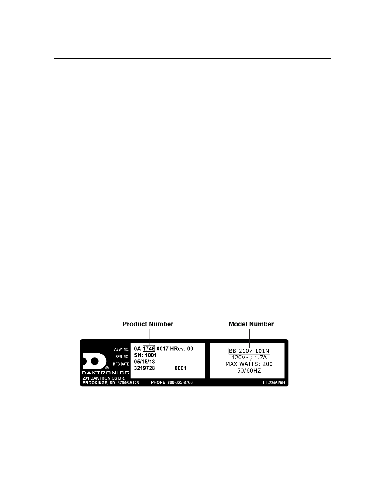
Figure 1: Specifications Label
Section 1: Introduction
This manual explains the troubleshooting of Daktronics Tuff Sport® Indoor LED Scoreboards,
Game/Shot Clocks, Statistics Panels, and Timing Displays. For additional information regarding the
safety, installation, operation, or service of these displays, refer to the Daktronics Customer Service
contact information in Section 4. This manual is not specific to a particular installation.
IMPORTANT SAFEGUARDS
Read and understand all instructions before servicing the scoreboard.
Disconnect display power when not in use or when servicing.
Disconnect display power before servicing power supplies to avoid electrical shock.
Power supplies run on high voltage and may cause physical injury if touched
while powered.
Do not modify the scoreboard structure or attach any panels or coverings to the
scoreboard without the express written consent of Daktronics.
Do not disassemble control equipment or electronic controls of the display; failure to
follow this safeguard will make the warranty null and void.
Do not drop control equipment or allow it to get wet.
Project-specific information takes precedence over any other general information found in
this manual. Such information may include:
Shop Drawings: describe mounting methods to structural elements, access method
(front or rear), and power and signal entrance points
System Risers: describe power and signal connections between display components
and the control location; may also include control room layout and schematic
To request project-specific information, contact a Daktronics sales coordinator or project manager.
1.1 Specifications Label
Power specifications as well as serial and model number information can be found on an ID
label on the display, similar to the one shown in Figure 1.
Please have the assembly number, model number, and the date manufactured on hand when
calling Daktronics customer service to ensure the request is serviced as quickly as possible.
Knowing the facility name and/or job number will also be helpful. Note that the Product
Number(s) are sometimes used to distinguish different generations of the scoreboards having
the same model number.
Introduction 1
Page 8
Main Component Labels
Part Type
Part Number
Individual circuit board
0P-XXXX-XXXX
Assembly; a collection of
circuit boards
0A-XXXX-XXXX
Wire or cable
W-XXXX
Fuse
F-XXXX
Transformer
T-XXXX
Metal part
M-XXX
Fabricated metal assembly
0S-XXXXXX
Specially ordered part
PR-XXXXX-X
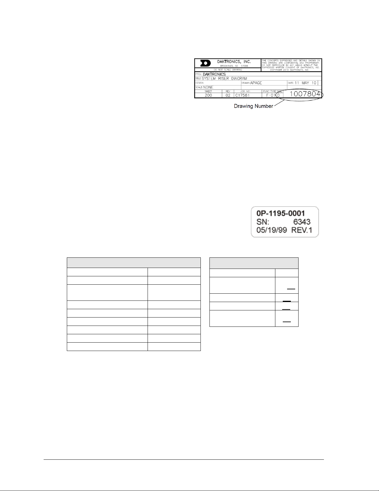
Figure 2: Daktronics Drawing Label
Figure 3: Part Label
Accessory Labels
Component
Label
Termination block for
power or signal cable
TBXX
Grounding point
EXX
Power or signal jack
JXX
Power or signal plug
for the opposite jack
PXX
1.2 Resources
Figure 2 illustrates a Daktronics drawing
label. The drawing number is located in the
lower-right corner of a drawing. This
manual refers to drawings by listing the last
set of digits and the letter preceding them.
In the example, the drawing would be
referred to as Drawing D-1007804. Any
drawings referenced in a particular section
are listed at the beginning of it as shown below:
Reference Drawing:
System Riser Diagram ..........................................................................Drawing D-1007804
Daktronics identifies manuals by the DD or ED number located on the cover page of each
manual. For example, this manual would be referred to as DD2481648.
1.3 Daktronics Nomenclature
Most components within this display carry a white label that lists
the part number of the unit. If a component is not found in the
Replacement Parts List in Section 2.8, use the label to order a
replacement. Figure 3 illustrates a typical label. The part number
is in bold.
Following the Replacement Parts List is the Daktronics Exchange Policy and the Repair &
Return Program. Refer to these instructions if replacing or repairing any display component.
1.4 Product Safety Approval
Daktronics indoor scoreboards are ETL-listed, tested to CSA standards and CE-labeled for
indoor use. Contact Daktronics with any questions regarding testing procedures.
2 Introduction
Page 9
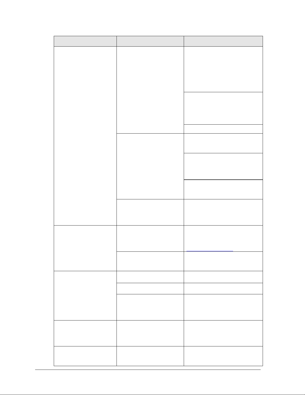
Problem
Possible Cause
Solution/Items to Check
Scoreboard doesn’t light
and console doesn’t work
No power to the scoreboard
Check that the main circuit breaker
for the scoreboard is on.
Check that the scoreboard is
receiving 120 (or 240) VAC power
(see Appendix A).
No power to console
Ensure the console is plugged into a
120 (or 240) VAC power supply.
Exchange the console with a
working one, and enter the correct
sport code and/or radio settings to
test. Replace console if necessary.
Scoreboard digits don’t light,
but console works
No wired signal from console
Check that the scoreboard is
receiving 120 (or 240) VAC power
(see Appendix A).
Check that the red DS5 (or DS2)
LED on the driver lights up when
sending commands from the control
console (see Section 2.4).
No radio signal from console
Cycle power to the scoreboard and
watch for radio receiver broadcast/
channel settings (see Section 2.5).
Section 2: Scoreboard Troubleshooting
IMPORTANT NOTES:
1. Always disconnect power before doing any repair work on the scoreboard.
2. Permit only qualified service personnel to access internal display electronics.
3. Disconnect power when not using the scoreboard.
Note: For assistance in the maintenance of team name message centers (TNMCs) or other optional
scoreboard message centers, refer to Section 3 or the service manual that accompanies those units.
2.1 Troubleshooting Table
The table below lists potential problems with the scoreboard and indicates possible causes
and corrective actions. This list does not include every symptom that may be encountered,
but it does present several of the most common situations that may occur.
Many of the solutions offered below provide references to other sections within this manual
or to supplemental product manuals with further detail on how to fix the problem.
If a problem occurs that is not listed or that cannot be resolved using the solutions in the
following table, contact Daktronics using the information provided in Section 4.
Scoreboard Troubleshooting 3
Page 10
Problem
Possible Cause
Solution/Items to Check
Check that the green POWER and
amber RADIO IN RANGE indicators
on the radio receiver in the
scoreboard light up when the control
console is powered on (see Section
2.5). Keep the console between 20500' (6-152 m) from the scoreboard.
Move the console 20-30' (6-9 m)
from the scoreboard and test again.
Verify that both the console and
scoreboard antennae are securely
tightened and in a vertical position.
Replace the radio receiver.
No signal to driver
Check that the scoreboard is
receiving 120 (or 240) VAC power
(see Appendix A).
Check that the red DS5 (or DS2)
LED on the driver lights up when
sending commands from the control
console (see Section 2.4).
Exchange the driver with a working
one of the same part #. Replace if
necessary (see Section 2.4).
No power to driver
Check that the red DS8 (or green
DS1) LED on the driver is always lit
up when the scoreboard is powered
on (see Section 2.4).
Scoreboard digits light, but
not in the correct order
Incorrect sport code
Ensure the correct sport code is
being used for the scoreboard
model. Refer to the appropriate
control console manual.
Incorrect driver address
Check that all scoreboard drivers
are set to the correct addresses
(see Section 2.4)
Scoreboard digits light,
console works, but no
display on scoreboard
No wired signal from console
(see solution on previous page)
No radio signal from console
(see solution on previous page)
Bad/damaged field wiring
Check that the red DS5 (or DS2)
LED on the driver lights up when
sending commands from the control
console (see Section 2.4)
Scoreboard works, but some
LEDs always stay on
Short in digit or indicator circuit
Exchange the digit/indicator with a
working one of the same part # to
verify the problem. Replace if
necessary (see Section 2.3).
Scoreboard works, but some
LEDs do not light or they
blink
Bad connection
Verify the connector on the back of
the digit circuit board is secure
(see Section 2.3).
4 Scoreboard Troubleshooting
Page 11
Problem
Possible Cause
Solution/Items to Check
Bad digit or driver
Exchange the digit/driver with a
working one of the same part # to
verify the problem. Replace if
necessary (see Section 2.3 for
digits or Section 2.4 for drivers).
Scoreboard works, but some
digits do not light
Bad digit or driver
(see solution above)
Incorrect sport code
(see solution on previous page)
Incorrect driver address
(see solution on previous page)
Wrong console controlling
scoreboard
Another console’s radio signal may
be transmitting to the scoreboard.
Radio interference
There may be other radio
transmissions in the area that
overpower the console. If it is not
possible to disable the interfering
device, It may be necessary to run a
wired signal connection instead.
Scoreboard works, but a
certain section of digits do
not light
Bad multi-section connection
Verify power/signal interconnects
between scoreboard sections are
properly connected. Refer to the
appropriate schematic drawings.
Bad transformer
Exchange the transformer with a
working one of the same part # to
verify the problem. Replace if
necessary.
Figure 4: Power Warning Label
2.2 Component Locations & Access
All indoor scoreboards are front-access, meaning that internal electronic components and
digits are reached by opening a digit panel on the front of the display.
Digit panels are typically held in place on the scoreboard face by screws. To remove a digit,
simply unfasten the screws and carefully lift it from the cabinet. The power/signal plug can
then be removed from the connector on the back of the digit to completely free the digit and
access internal components.
Component location varies with each scoreboard model,
but drivers and power and signal components are
typically mounted inside the scoreboard behind a digit
panel. To locate the driver(s), look for a warning label
similar to that shown in Figure 4.
For model-specific component layouts and access
locations, refer to the electrical and signal or component
location drawings attached to the product specifications
Scoreboard Troubleshooting 5
sheets listed in Appendix A.
Page 12
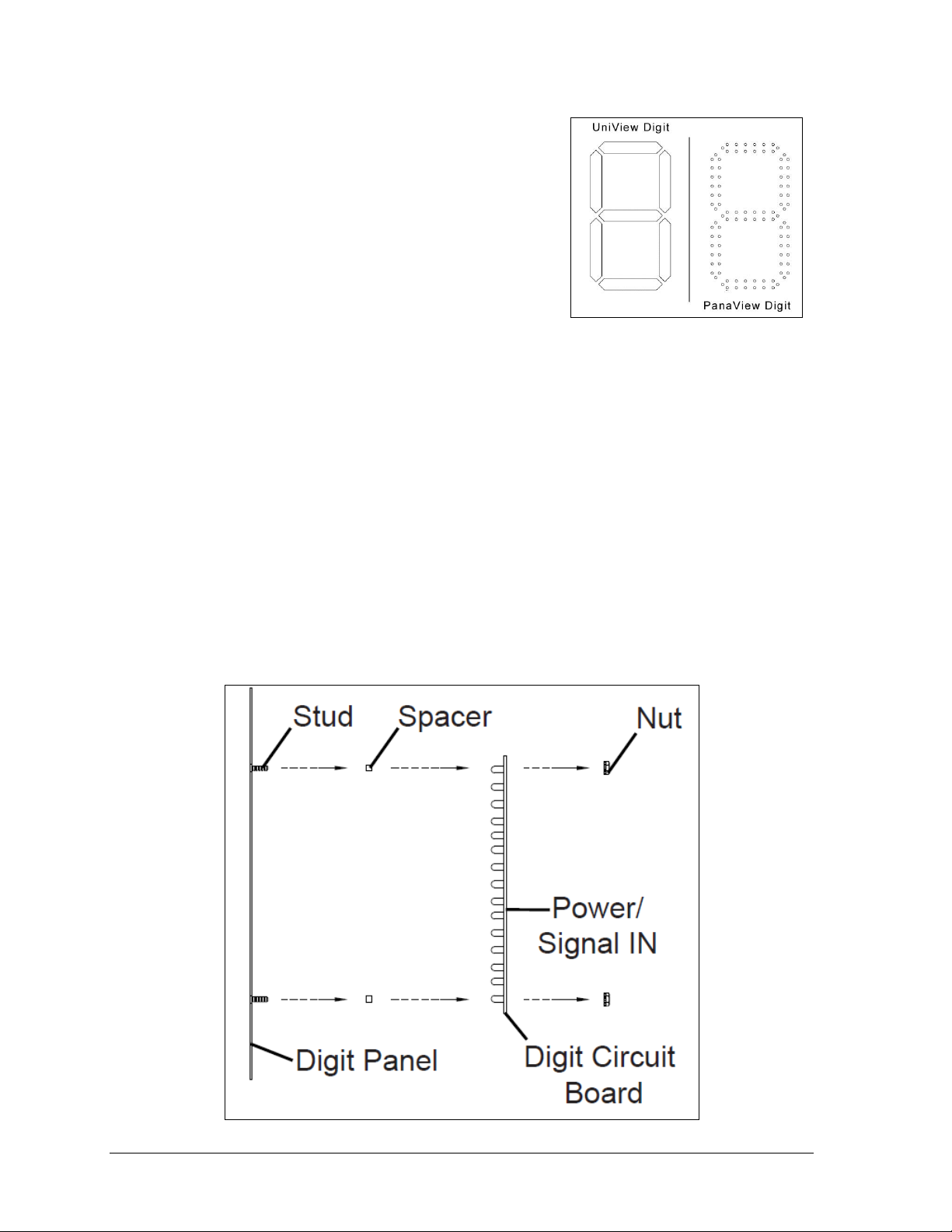
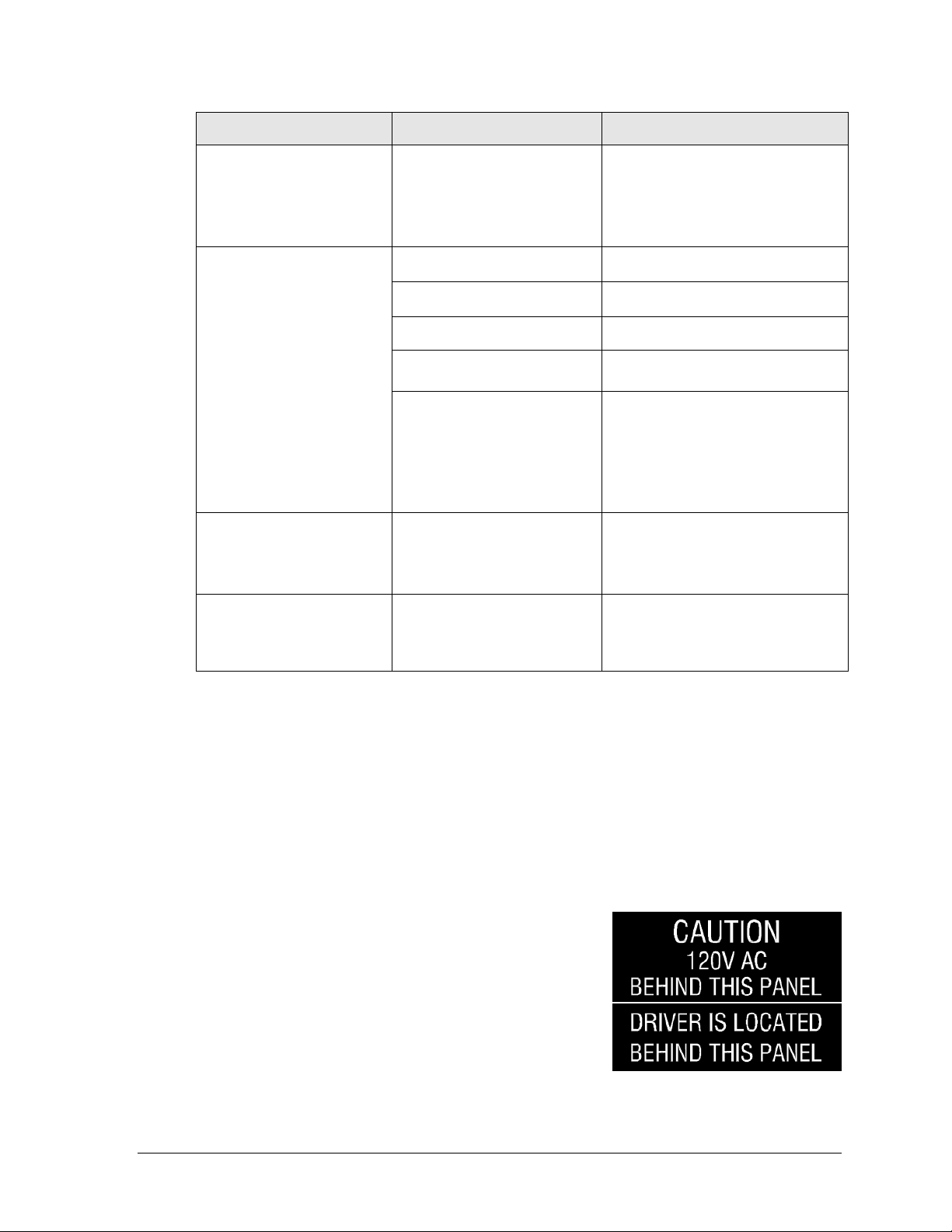
Figure 5: Digit Types
Figure 6: PanaView Digit Assembly
2.3 Replacing Digits
LEDs are embedded in a circuit board that is mounted
to the back of the digit panel. Do not attempt to remove
individual LEDs. In the case of a malfunctioning LED or
digit segment, replace the entire digit circuit board.
The process of replacing digits varies by whether it is a
PanaView® digit or UniView® digit (Figure 5).
PanaView
To replace a PanaView digit circuit board (Figure 6):
1. Open the digit panel as described in Section 2.2.
2. Disconnect the power/signal connector from the back of the digit by squeezing
together the locking tabs and pulling the connector free.
3. Use a
4. Position a new digit over the studs (making sure the small plastic spacers are still in
5. Reconnect the power/signal connector.
6. Secure the digit panel to the display with the screws, then power up and test the
9
/32" nut driver to remove the nuts securing the digits to the inside of the panel,
and then lift the digit off the stud inserts.
place) and tighten the nuts.
Note: This is a keyed connector and it will attach in one way only. Do not attempt to
force the connection.
display to see if changing the digit has resolved the problem.
6 Scoreboard Troubleshooting
Page 13

Figure 7: UniView Digit Assembly
UniView
To replace a UniView digit circuit board (Figure 7):
1. Open the digit panel as described in Section 2.2.
2. Disconnect the power/signal connector from the back of the digit by squeezing
together the locking tabs and pulling the connector free.
3. Use a
4. Position a new digit over the standoffs, and tighten the nuts. It may be necessary to
5. Reconnect the power/signal connector.
6. Secure the digit panel to the display with the screws, then power up and test the
9
/32" nut driver to remove the nuts securing the digits to the aluminum
standoffs, and then lift the digit off the standoff/diffuser assembly.
also tighten the standoffs if they became loose while removing the nuts.
Note: This is a keyed connector and it will attach in one way only. Do not attempt to
force the connection.
display to see if changing the digit has resolved the problem.
Scoreboard Troubleshooting 7
Page 14

Figure 8: 16-Column Driver Tray Components
2.4 LED Drivers
In each scoreboard, one or more LED drivers perform the task of switching LEDs on and off.
LED drivers are mounted to a driver tray. Refer to Figure 8 to view the typical components of
a Tuff Sport driver tray.
All Tuff Sport scoreboards and statistics displays use 16-column drivers (Figure 8), while
some smaller displays use 4-column drivers. Several scoreboard models contain more than
one driver to accommodate all of the digits and indicators. Refer to the drawings attached to
the product specification sheets listed in Appendix A to determine the type and number of
drivers for a particular scoreboard model. Also refer to Appendix B to find the scoreboard’s
schematic drawings.
8 Scoreboard Troubleshooting
Page 15

LED
Function
Operation
Summary
DS1
Radio/
RS-232 RX
Blinking
or off
DS1 will be blinking when the driver is receiving radio signal
and off when there is no signal.
DS2
Status
Blinking
DS2 will be blinking at one second intervals to indicate the
driver is running.
DS5
Signal RX
Blinking
or off
DS5 will be blinking when the driver is receiving current loop
signal and off when there is no signal.
DS8
Power
Steady on
DS8 will be on and steady to indicate the driver has power.
LED
Color
Function
Operation
Summary
DS1
DS2
DS7
Green
Power
Steady on
DS1 (16-column) / DS2 (4-column) / DS7 (4column MASC) will be on and steady to indicate
the driver has power.
DS2
DS1
DS8
Red
Signal RX
Steady on
or blinking
DS2 (16-column) / DS1 (4-column) / DS8 (4column MASC) will be on or blinking when the
driver is receiving a signal and off when there is no
signal.
DS3
Amber
Status
Blinking
DS3 will be blinking at one second intervals to
indicate the driver is running (not available on 4-
column LED drivers).
When troubleshooting driver problems, several LEDs provide diagnostic information.
The number of LEDs and their function depends on the driver type.
Note: While it is necessary to have the scoreboard powered on to check the LED indicators,
always disconnect scoreboard power before servicing.
16-Column “Gyrus” Drivers
16-Column Drivers (prior to April 2015) & 4-Column Drivers
Multiple Drivers
Scoreboards that require multiple drivers operate using a primary/secondary driver
configuration. The two drivers have been designed to simply plug into one another, and this
is done at the factory, so no additional on-site connection is necessary.
If it appears as though only a certain group of digits on the scoreboard is not functioning,
there may be a problem with the secondary driver(s) or the power/signal connection from
the other driver(s).
Note: The BB-2117 and BB-2119 require an interconnect cable between their driver
and the driver in the BB-2116. Refer to appropriate schematics listed in Appendix B.
Scoreboard Troubleshooting 9
Page 16

Figure 9: Driver Address Dials
Figure 10: Address Jack J19,
16-Column Driver
Replacing a Driver
If the driver status indicators do not appear to be working correctly, it may be necessary to
replace the driver.
1. Open the digit panel or scoreboard face panel as described in Section 2.2.
2. Disconnect all connectors from the driver by squeezing together the locking tabs and
pulling the connectors free. It may be helpful to label the cables to know which cable
goes to which connector when reattaching the driver.
3. Remove the wing nuts securing the driver to the driver tray.
4. Carefully lift the driver from the display and place it on a clean, flat surface.
5. Position a new driver over the screws and tighten the nuts.
6. Reconnect all power/signal connectors.
Note: The connectors are keyed and will attach in one way only. Do not attempt to
force the connections.
7. Ensure the driver is set to the correct address (refer to Setting the Driver Address).
8. Close and secure the access panel, then power up and test the scoreboard to see if
changing the driver has resolved the problem.
Setting the Driver Address
Since the same LED drivers can be used for many scoreboard models, each driver must be set
to receive the correct signal input, or address, for the model being used. The way the address
is set depends on the driver type:
For 16-column “Gyrus” drivers, addresses
For older 16-column and 4-column drivers, addresses
10 Scoreboard Troubleshooting
are set through the S2 (L) and S3 (H) rotary
switches on the driver (Figure 9) using a
small flathead screwdriver.
Refer to the tables on the following pages to
determine the correct address setting of the
driver(s) in a particular scoreboard model
and see Drawing B-1198765 in Appendix C
for addressing information of driver
addresses 1 – 255.
are set with jumper wires in a 12-pin plug which mates
with jack J19 on the driver (Figure 10).
It may be possible to reuse the same address plug from
the driver that was replaced. If not, first refer to the
table on the following page to determine the correct
address setting of the driver(s) in a particular
scoreboard model. Then see Drawing A-115078 in
Appendix C for a listing of the wire/pin connections
for driver addresses 1 – 128.
Page 17

Model
Driver #
& Address
BB-2101
BB-2102
BB-2103
BB-2104
BB-2105
BB-2106
BB-2107
BB-2108
BB-2116
BB-2121
BB-2122
BB-2125
BB-2126
BB-2142
BB-2143
BB-2144
BB-2146*
BB-2147*
BB-2153
BB-2154
BB-2155
BB-2156
A1 17
BB-2109
BB-2114
BB-2115
BB-2130
BB-2131
BB-2152
A1 1
BB-2111
BB-2132
A1 1
A2 2
BB-2117
A2 14
BB-2119
A2 17
BB-2123
BB-2124
A1 17
A2 14
SD-2101
SD-2102
Left (Home):
A1 23
A2 24
Right (Guest):
A1 25
A2 26
SD-2103
SD-2104
Left (Home):
A1 23
A2 27
A3 24
Right (Guest):
A1 25
A2 28
A3 26
SD-2106
A1 15
Model
Driver #
& Address
CU-2001
A1 11
A2 12
SQ-2001
A1 11
H-2101
H-2111
H-2112
A1 71
H-2104
H-2105
H-2106
H-2107
H-2108
H-2109
A1 71
A2 72
A3 73
H-2102
H-2115
Left (Home):
A2 72
Right (Guest):
A3 73
H-2114
A1 74
H-2103
N/A
TI-2030
A1 11
TI-2101
TI-2200
A1 1
TI-2102
A1 4
TI-2103
A1 97
VB-2101
A1 17
Tennis (See Drawing B-3019367)
PN-2101
N/A
* These displays are composed of
scoreboards and LED message centers.
Refer to the message center manual for
more information on specifications,
operation, and servicing.
Scoreboard Troubleshooting 11
Page 18

Figure 11: All Sport Radio Settings (Clock)
Figure 12: RC-100 Radio Settings (Clock)
RA DI O S ETT I NGS
BC AST 1 CH AN 0 1
RA DI O C HAN NEL
DEFAULT: 01
2.5 Radio Connections
To determine the settings for radio connections between the scoreboard and control console:
1. Power off any radio-equipped consoles in the area.
2. Cycle power to the scoreboard, and watch for the radio settings. These settings
appear in different locations based on the scoreboard layout:
When using the All Sport 5000
controller, the scoreboard will
display “bX CY” where X is the
Broadcast group number and Y is
the Channel number. The default is
b1C1.
o If there is a clock, the settings
appear in the first four clock
digits (Figure 11).
o If there is no clock, the settings
should appear in the Home and
Guest score digits, but this may
vary by scoreboard model.
When using the RC-100 controller,
the scoreboard will display “CXX”,
where the XX is a channel from 0115 (Figure 12). The default is
channel 01.
Note: If these settings do not appear, the radio receiver may need to be
repaired/replaced.
To make sure the console radio settings match the receiver in the scoreboard, refer to the
appropriate control console manual.
All Sport Radio Settings RC-100 Radio Settings
Radio Interference
If it has been determined that a nearby scoreboard’s radio signal is interfering, the settings of
the radio receiver or wireless base station inside the scoreboard(s) must be changed.
1. To locate the radio receiver or base station, simply look for the black antenna sticking
out the front of the scoreboard. Component location drawings also show the exact
position where the radio receiver will be mounted.
2. Open the access panel to which the receiver is attached as described in Section 2.2.
The channel selection process varies depending on whether the scoreboard is equipped with
or a radio receiver (All Sport 5000) or a wireless base station (RC-100).
12 Scoreboard Troubleshooting
Page 19

Figure 13: Radio Receiver w/ Cover
Figure 14: Radio Receiver Switches
Radio Receiver (All Sport 5000)
1. The radio receiver has a plastic cover with a
window to view status indicators (Figure 13).
Note: While it is necessary for the scoreboard to
be powered on to check the indicators, always
disconnect scoreboard power before servicing.
2. Remove the four screws in each corner using a
#2 Philips screwdriver and lift off the cover.
3. The process of changing the radio settings
depends on the generation of the radio.
Refer to the instructions below and Figure 14.
Gen V (blue label): Use a small flathead screwdriver to set the CHAN switch to
a new channel (1-8). Move the jumper wire on the J4 or J5 BCAST jacks to a new
broadcast group (1-4) as needed.
Gen VI (gray label): Use a small flathead screwdriver to set the CHAN and
BCAST switches to a new channel and broadcast group (1-8) as needed. Be sure
to always leave FUNC set to “1”.
4. Screw the cover back on and securely close the access panel.
5. Enter the correct sport code and new radio settings into the console to test the radio
Refer to the Gen V Radio Installation Manual (ED-13831) or the Gen VI Radio Installation
Manual (DD2362277) for more information.
Scoreboard Troubleshooting 13
control (refer to the appropriate control console manual).
Page 20

Figure 15: Channel Select Switch (Internal Receiver)
Base Station (RC-100)
1. Use a small flathead screwdriver to set the S1 switch (Figure 15) to the desired
channel (1-15).
2. Securely close the scoreboard access panel.
3. Enter the correct channel setting and sport code into the RC-100 handheld controller
to test the radio connection.
For more information, refer to the Remote Control System RC-100 All Sport Operation Manual
(ED-15133).
2.6 Segmentation & Digit Designation
In each digit, certain LEDs always go on and off together. These groupings of LEDs are called
segments. Drawing A-38532 in Appendix C details which connector pin is wired to each digit
segment and the wiring color code used throughout the scoreboard.
The Electrical and Signal drawings and Component Location drawings also specify the driver
connectors controlling the digits. Numbers shown in hexagons in the upper half of each digit
indicate which connector is wired to that digit.
2.7 Schematics
For advanced scoreboard troubleshooting and repair, it may be necessary to consult the
schematic drawings. Listed in Appendix B, schematic drawings show detailed power and
signal wiring diagrams of internal display components such as drivers, horn interface cards,
and transformers as well as optional components like TNMCs, radio receivers, and end of
period (EOP) lighting.
14 Scoreboard Troubleshooting
Page 21

Description
Daktronics Part #
Horn, 120V with capacitor
0A-1152-0332
16-Column LED Driver
0A-1782-0100
PanaView Digit, 5" amber LED, 7-seg
0P-1150-0081
LED driver, 4-column (BB-2114 & TI-2103 only)
0P-1150-0130
PanaView Digit, 5" red LED, 7-seg
0P-1150-0200
PanaView Digit, 5" red LED, 2-seg
0P-1150-0254
16 VAC LED VHI
0P-1150-0267
LED driver, 4-column (TI-2200 only)
0P-1192-0067
PanaView Digit, 7" red LED, 7-seg
0P-1230-0048
PanaView Digit, 7" amber LED, 7-seg
0P-1230-0049
PanaView Digit, 7" red LED, 2-seg
0P-1230-0058
PanaView Digit, 7" amber LED, 2-seg
0P-1230-0059
PanaView Digit, 10" red LED, 7-seg
0P-1230-0050
PanaView Digit, 10" amber LED, 7-seg
0P-1230-0051
PanaView Digit, 10" red LED, 2-seg
0P-1230-0060
PanaView Digit, 10" amber LED, 2-seg
0P-1230-0061
PanaView Digit, 13" red LED, 7-seg
0P-1230-0052
PanaView Digit, 13" amber LED, 7-seg
0P-1230-0053
PanaView Digit, 13" red LED, 2-seg
0P-1230-0062
PanaView Digit, 13" amber LED, 2-seg
0P-1230-0063
PanaView Digit, 18" red LED, 7-seg
0P-1230-0056
PanaView Digit, 18" amber LED, 7-seg
0P-1230-0057
PanaView Digit, 18" red LED, 2-seg
0P-1230-0066
PanaView Digit, 18" amber LED, 2-seg
0P-1230-0067
PanaView B-Bonus Indicator, Amber
0P-1150-0217
PanaView Arrow, Amber, 3"
0P-1150-0164
PanaView Arrow, Red, 3"
0P-1150-0185
PanaView Colon, Red
0P-1230-0070
PanaView Colon, Amber
0P-1230-0071
UniView Digit, 7" Red LED, 7-seg
0P-1230-0023
UniView Digit, 7" Amber LED, 7-seg
0P-1230-0024
UniView Digit, 7" Red LED, 2-seg
0P-1230-0031
UniView Digit, 7" Amber LED, 2-seg
0P-1230-0032
UniView Digit, 10" Red LED, 7-seg
0P-1230-0025
UniView Digit, 10" Amber LED, 7-seg
0P-1230-0026
UniView Digit, 10" Red LED, 2-seg
0P-1230-0033
UniView Digit, 10" Amber LED, 2-seg
0P-1230-0034
UniView Digit, 13" Red LED, 7-seg
0P-1230-0027
UniView Digit, 13" Amber LED, 7-seg
0P-1230-0028
UniView Digit, 13" Red LED, 2-seg
0P-1230-0035
UniView Digit, 13" Amber LED, 2-seg
0P-1230-0036
UniView Digit, 18" Red LED, 7-seg
0P-1230-0040
UniView Digit, 18" Amber LED, 7-seg
0P-1230-0041
UniView Digit, 18" Red LED, 2-seg
0P-1230-0044
2.8 Replacement Parts
Refer to the following table for Daktronics scoreboard replacement parts.
Scoreboard Troubleshooting 15
Page 22

Description
Daktronics Part #
UniView Digit, 18" Amber LED, 2-seg
0P-1230-0045
UniView 1 Position Indicator, Red
0P-1230-0037
UniView 3 Position Indicator, Red & Amber
0P-1230-0038
UniView 1 Position Indicator, Amber
0P-1230-0039
UniView Colon, Red
0P-1230-0068
UniView Colon, Amber
0P-1230-0069
Digit; 13" Red LED, 7-seg w/ tenths, NBA
0P-1230-0143
2" Decimal, Red LED, NBA
0P-1230-0144
Power supply, 12V, 85-264VAC, 150W
A-2855
Transformer, 115/230 V @ 2 A
T-1063
Transformer, 115/230 V @ 6.25 A
T-1066
Cable, 20' phone plug
W-1236
Cable, 50' phone plug
W-1237
Cable, 30' phone plug
W-1238
Cable, 10' phone plug
W-1340
See Section 4 for information on Daktronics Exchange and Repair and Return program.
16 Scoreboard Troubleshooting
Page 23

Matrix Size
# of 8x16
Modules
Pixel Spacing
Active Display Area
Weight*
8x48
3
19 mm (0.75")
6" x 36" (152 mm x 914 mm)
15 lb (7 kg)
25 mm (1")**
8" x 48" (203 mm x 1219 mm)
20 lb (9 kg)
8x32
2
25 mm (1")***
8" x 32" (203 mm x 813 mm)
15 lb (7 kg)
8x16
1
19 mm (0.75")
6" x 12" (152 mm x 305 mm)
15 lb (7 kg)
Figure 16: Basketball Scoreboard with TNMCs and Electronic Captions
Section 3: TNMC & Electronic Caption
Troubleshooting & Maintenance
IMPORTANT NOTES:
1. Always disconnect scoreboard power before doing any repair work on the displays.
2. Permit only qualified service personnel to access internal display electronics.
3. Disconnect power when not using the scoreboard.
3.1 Display Overview
Team Name Message Centers (TNMCs) are programmable LED displays that allow users to
show custom Home and Guest names or messages of ~15 characters on the scoreboard in
place of static vinyl captions. TNMCs are typically ordered factory-installed, but they may
also be field-mounted after the scoreboard is in place. Characters are shown on one line using
single- or double-stroke fonts.
Electronic captions, on the other hand, are pre-programmed to only show specific labels to
match the captions for a particular sport mode, making it much simpler to switch between
sports. Characters are shown on one line using single-stroke fonts.
Primary matrix size is 8x48 with 0.75" pixel spacing. Figure 16 shows examples of both
TNMCs and electronic captions.
* Weight shown is for a pair of displays.
** Only used on BB-2116 and H-2101.
*** Only used on tennis scoreboards.
TNMC & Electronic Caption Troubleshooting & Maintenance 17
Page 24

Symptom/Condition
Possible Remedy
One or more LEDs on a single
module fails to light or turn off
Check/replace the ribbon cables on the module.
Replace the module (see Section 3.6).
A section of the display is not
working; section extends all the
way to the right side of the display
Check/replace the ribbon cables running to the first module
that is not working.
Replace the first module/driver on the left side of the first
module that is not working (see Section 3.6).
Replace the second module that is not working
(see Section 3.6).
Replace the power supply assembly on the first module that
is not working (see Section 3.6).
One row of modules does not work
or is garbled
Replace the first module (see Section 3.6).
Replace the display driver (see Section 3.6).
A group of modules which shares
the same power supply assembly
fails to work
Replace the power supply assembly (see Section 3.6).
Entire display fails to work
Check for proper line voltage into the power termination panel.
Check/replace the ribbon cable to the modules.
Check the voltage settings on the power supplies.
Check/replace the signal cable to the display driver.
Replace the display driver (see Section 3.6).
3.2 Initialization Information at Startup
Every time the display is powered up and there is no All Sport® signal present, the display
will run through an initialization process, during which it will test all LEDs and addresses.
First, the message center will display the proper address number.
If the entire display fails at startup, power may not be properly connected, or the address
setting may not be correct on the display driver. Check both in the event of a failure.
3.3 Display Troubleshooting Table
The table below lists potential problems with the display and indicates possible causes and
corrective actions. This list does not include every symptom that may be encountered, but it
does present several of the most common situations that may occur.
Many of the solutions offered below provide references to other sections within this manual
with further detail on how to fix the problem.
If a problem occurs that is not listed or that cannot be resolved using the solutions in the
following table, contact Daktronics using the information provided in Section 4.
18 TNMC & Electronic Caption Troubleshooting & Maintenance
Page 25

3.4 Power & Signal Summary
Refer to Drawing B-1132254 or B-1133209 in Appendix B for detailed schematics about
display power and signal routing.
Display signal routing can be summarized as follows:
1. Data from the All Sport
(or radio) into the scoreboard.
2. The signal then travels through the driver, typically re-driven from the driver TB-31 to
the current loop interface (CLI) cards located on the right-hand module of each display
and then to the first LED module via ribbon cable.
3. The signal relays from module to module via ribbon cable in daisy-chain style until it
reaches the last module in the display.
Display power routing can be summarized as follows:
1. Incoming power from the power cord terminates at the main scoreboard LED driver tray.
2. Using interconnect harnesses, the power for TNMCs is passed from the driver tray to
the Home display power supply, and then to the Guest display power supply. In stat
display electronic captions, each power supply receives power from a separate driver.
3. Power from the power supplies is relayed to all display modules.
4. The modules draw their power directly from the power supply assemblies; the
display driver receives power out from the first module via ribbon cable.
®
controller (or DakTennis™ software) travels via signal cable
3.5 Component Locations & Access
To access the internal components of the display, simply remove the screws on either side
of the face panel that secure it to the scoreboard. Carefully remove the face panel from
the scoreboard, as there will be several cables connected to it. Drawings B-1130367 and
B-1130784 in Appendix C provide a detailed view of each display component and the
connections between them.
3.6 Replacing a Component
1. Access the internal components as described in Section 3.5.
2. Disconnect all power/signal cables from the component by squeezing together the
locking tabs and pulling the connectors free. It may be helpful to label the cables to
know which cable goes to which connector when reattaching.
3. Remove the hardware securing the component to the display face panel.
Note: In order to replace the right-most module circuit board (when viewing the
display from the front), the power supply bracket and driver circuit board must be
removed from it first.
4. Position a new component on the display face panel and tighten the hardware.
5. Reconnect all power/signal connectors.
6. Power up and test the scoreboard/display to see if the problem has been resolved.
Refer to Figure 17 for display assembly, showing the power supply, driver, and modules.
TNMC & Electronic Caption Troubleshooting & Maintenance 19
Page 26

LED Name
Color
Illumination Summary
DS1 PWR
Green
Steady on or blinking when the driver has power
DS2 RX
Red
Steady on or blinking when the driver is receiving
and off when there is no current loop (CL) signal
Figure 17: Display Assembly, Top View
Figure 18: Display Driver
3.7 Display Drivers
Display drivers, also known as controllers
or shift cards, use a 12-pin plug that
mates with jack J4 to set the address.
For TNMCs, the address plug is set to 1
(221). A typical Player-Foul-Points
electronic caption for statistics displays
uses address 3 (223) while a scoreboard
with electronic captions uses address 8
(228). Pin 11 on the address plug selects
whether to show Home data (connected)
or Guest data (not connected). Refer to
Drawing A-123794 in Appendix C for
addressing information.
Note: Refer to Drawing A-3019367
for TNMC addressing information of
tennis systems with up to 12 courts.
Figure 18 illustrates some of the primary jacks and indicators of a display driver.
Diagnostic LEDs
The following table explains the functions of the primary diagnostic LEDs on the drivers:
20 TNMC & Electronic Caption Troubleshooting & Maintenance
Page 27

Part Description
Part Number
Indoor TNMC Card
0P-1150-0206
Module; 8x16, Amber (1")
0P-1186-0104
Module; 8x16, Red (1")
0P-1186-0111
Module; 8x16, Amber (0.75")
0P-1186-0112
Module; 8x16, Red (0.75")
0P-1186-02204
Power Supply; 12V @ 8.5A, 85-264VAC (for 1" mods)
A-1555
Power Supply; 5V @ 10A, 85-264VAC (for 0.75" mods)
A-1568
Cable; 18 pos, Ribbon, 6"
W-1320
3.8 Display Maintenance
Complete a yearly inspection to maintain safe and dependable display operation.
This inspection should address the following issues:
Loose Hardware: Verify that fasteners, such as bolts and rivets, have not come loose.
Check and tighten or replace fasteners as required.
Excessive Dust Buildup: It may be necessary to occasionally vacuum the inside of
the display cabinet to remove dust/dirt buildup that may interfere with airflow.
Corrosion: Check the paint, and look for possible corrosion
Make repairs or take corrective action immediately if any of the preceding conditions are present.
3.9 Replacement Parts List
The following table contains display components that may have to be replaced. Many of the
components within the display itself have attached part number labels.
See Section 4 for information on Daktronics Exchange and Repair and Return program.
TNMC & Electronic Caption Troubleshooting & Maintenance 21
Page 28

Page 29

Market Description
Customer Service Number
Schools (including community/junior colleges), religious
organizations, municipal clubs and community centers
877-605-1115
Universities and professional sporting events, live events
for auditoriums and arenas
866-343-6018
Section 4: Daktronics Exchange and Repair &
Return Programs
4.1 Exchange Program
The Daktronics Exchange Program is a service for quickly replacing key components in need
of repair. If a component fails, Daktronics sends a replacement part to the customer who, in
turn, returns the failed component to Daktronics. This decreases equipment downtime.
Customers who follow the program guidelines explained below will receive this service.
Before Contacting Daktronics
Identify these important numbers:
Display Assembly Number: ______________________________________________________
Display Model Number: _________________________________________________________
Job/Contract Number: __________________________________________________________
Date Manufactured/Installed: ___________________________________________________
Daktronics Customer ID Number: ________________________________________________
To participate in the Exchange Program, follow these steps:
1. Call Daktronics Customer Service.
2. When the exchange part is received, mail the old part to Daktronics.
If the replacement part fixes the problem, send in the problem part being replaced.
a. Package the old part in the same shipping materials in which the replacement
part arrived.
b. Fill out and attach the enclosed UPS shipping document.
c. Ship the part to Daktronics.
3. The defective or unused parts must be returned to Daktronics within 5 weeks of
initial order shipment.
If any part is not returned within five (5) weeks, a non-refundable invoice will be
presented to the customer for the costs of replenishing the exchange parts inventory
with a new part.
Daktronics reserves the right to refuse parts that have been damaged due to acts of
nature or causes other than normal wear and tear.
Daktronics Exchange and Repair & Return Programs 23
Page 30

4.2 Repair & Return Program
For items not subject to exchange, Daktronics offers a Repair & Return Program. To send a
part for repair, follow these steps:
1. Call or fax Daktronics Customer Service:
Refer to the appropriate market phone number in the chart on the previous page.
Fax: 605-697-4444
2. Receive a case number before shipping.
This expedites repair of the part.
3. Package and pad the item carefully to prevent damage during shipment.
Electronic components, such as printed circuit boards, should be placed in an
antistatic bag before boxing. Daktronics does not recommend using packing ‘peanuts’
when shipping.
4. Enclose:
name
address
phone number
the case number
a clear description of symptoms
Shipping Address
Daktronics Customer Service
[Case #]
201 Daktronics Drive, Dock E
Brookings, SD 57006
4.3 Daktronics Warranty and Limitation of Liability
The Daktronics Warranty and Limitation of Liability is located in Appendix D. The Warranty
is independent of Extended Service agreements and is the authority in matters of service,
repair, and display operation.
24 Daktronics Exchange and Repair & Return Programs
Page 31

Model
Spec Sheet
Model
Spec Sheet
Model
Spec Sheet
Model
Spec Sheet
BB-2101
DD2481847
BB-2126
DD2481913
H-2106
DD2541499
TN-2501
DD2650450
BB-2102
DD2481850
BB-2130
DD2481915
H-2107
DD2541501
TN-2503
DD2650454
BB-2103
DD2481852
BB-2131
DD2481917
H-2108
DD2541505
TN-2504
DD2650457
BB-2104
DD2481853
BB-2132
DD2481921
H-2109
DD2541516
TN-2505
DD2650463
BB-2105
DD2481855
BB-2142
DD2481922
H-2111
DD2541518
TN-2560
DD2650465
BB-2106
DD2481859
BB-2143
DD2481927
H-2112
DD2541519
TN-2561
DD2650467
BB-2107
DD2481865
BB-2144
DD2481929
H-2114
DD2541521
TN-2562
DD2650469
BB-2108
DD2481866
BB-2146
DD2481933
H-2115
DD2541522
TN-2563
DD2650470
BB-2109
DD2481869
BB-2147
DD2481936
PN-2101
DD2481946
VB-2101
DD2568754
BB-2111
DD2481872
BB-2152
DD2061941
SD-2101
DD2481954
BB-2114
DD2481873
BB-2153
DD2213495
SD-2102
DD2481956
BB-2115
DD2481875
BB-2154
DD2475304
SD-2103
DD2481959
BB-2116
DD2481881
BB-2155
DD2457495
SD-2104
DD2481962
BB-2117
DD2481884
BB-2156
DD2475313
SD-2106
DD2481964
BB-2119
DD2481889
CU-2001
DD1862875
SQ-2001
DD2962304
BB-2121
DD2481893
H-2101
DD2541481
TI-2030
DD1747844
BB-2122
DD2481896
H-2102
DD2541488
TI-2101
DD2594852
BB-2123
DD2481901
H-2103
DD2541491
TI-2102
DD2594853
BB-2124
DD2481909
H-2104
DD2541494
TI-2103
DD2889079
BB-2125
DD2481911
H-2105
DD2541497
TI-2200
DD2594855
Appendix A: Specifications
Click the links below to view the product specification sheets for the scoreboards in this manual.
Product-specific mechanical and electrical drawings are included with each spec sheet.
Note: Refer to Figure 1 to determine a scoreboard’s model number.
Specifications 25
Page 32

Page 33

Models
Schematic Drawing
120 VAC
240 VAC
BB-2101
BB-2102
BB-2103
BB-2104
BB-2105
BB-2106
BB-2107
BB-2108
BB-2121
BB-2122
BB-2125
BB-2126
BB-2142
BB-2143
BB-2144
BB-2146
BB-2147
A-3013427
A-3022578
BB-2153
BB-2154
BB-2155
BB-2155
B-1130381
B-1130382
BB-2116
BB-2117
BB-2119
B-3024355
B-3024737
BB-2123
BB-2124
B-3024247
B-3024671
SD-2101
SD-2102
SD-2103
SD-2104
B-3022678
B-3024710
SD-2106
A-3013427
A-3022578
PN-2101
N/A
Hockey
Models
Schematic Drawing
120 VAC
240 VAC
H-2101
H-2111
H-2112
A-3013427
A-3022578
H-2104
H-2105
H-2106
H-2107
H-2108
H-2109
B-3024247
B-3024671
H-2102
H-2114
H-2115
A-3024301
A-3024645
H-2103
N/A
Shot Clocks
Models
Schematic Drawing
120 VAC
240 VAC
BB-2109
BB-2131
B-1046900
B-1046897
BB-2111
BB-2132
B-1046901
B-1046898
BB-2114
B-1045157
B-1045160
BB-2115
BB-2130
BB-2152
B-1045024
B-1045148
Team Name Message Centers
& Electronic Captions
Pixel Spacing
Schematic Drawing
3/4"
B-1132254
1"
B-1133209
Appendix B: Schematic Drawings
Use the tables below to determine the schematic drawing for a particular scoreboard model.
Click the links to view the schematic drawings.
Basketball & Stat Displays
Schematic Drawings 27
Page 34

Curling
Models
Schematic Drawing
120 VAC
240 VAC
CU-2001
B-3024247
B-3024671
Tennis
Models
Schematic Drawing
120 VAC
240 VAC
TN-2501
A-1196490
TN-2503
TN-2504
TN-2505
A-3013427
A-3022578
TN-2560
TN-2561
Team Score: B-1097081
TN-2562
TN-2563
Team Score: B-1110522
Squash
Models
Schematic Drawing
120 VAC
240 VAC
SQ-2001
A-1196490
Timing Displays
Models
Schematic Drawing
120 VAC
240 VAC
TI-2030
TI-2101
TI-2102
A-3013427
A-3022578
TI-2103
B-1184553
N/A
TI-2200
A-195063
N/A
Volleyball
Models
Schematic Drawing
120 VAC
240 VAC
VB-2101
A-3013427
A-3022578
28 Schematic Drawings
Page 35

Appendix C: Reference Drawings
Click the links below to view additional drawings referenced in this manual.
Drawing Title Drawing Number
Segmentation, 7 Segment Bar Digit ........................................................................................... A-38532
Address Table, 1 Through 128 ................................................................................................. A-115078
A/S 5000 Capable TNMC Shift Card; Specifications ................................................................ A-123794
Assembly and PWR/SIG Routing; 3/4" TNMC ....................................................................... B-1130367
Assembly and PWR/SIG Routing; 1" TNMC .......................................................................... B-1130368
Assembly and PWR/SIG Routing; Elec Captions ................................................................... B-1130784
Address Table; Rotary Switches H and L ............................................................................... B-1198765
Power and Address Details; Indoor Tennis Scoreboards ....................................................... B-3019367
Note: Site-specific system diagrams take precedence over any general setup drawings listed.
Reference Drawings 29
Page 36

Page 37

Appendix D: Daktronics Warranty and Limitation
of Liability
Daktronics Warranty and Limitation of Liability 31
Page 38

Page 39

DAKTRONICS WARRANTY & LIMITATION OF LIABILITY
This Warranty and Limitation of Liability (the “Warranty”) sets forth the warranty provided by Daktronics with respect to the Equipment. By accepting delivery of the
Equipment, Purchaser agrees to be bound by and accept these terms and conditions. Unless otherwise defined herein, all terms within the Warranty shall have the
same meaning and definition as provided elsewhere in the Agreement.
DAKTRONICS WILL ONLY BE OBLIGATED TO HONOR THE WARRANTY SET FORTH IN THESE TERMS AND CONDITIONS UPON RECEIPT OF FULL PAYMENT FOR THE
EQUIPMENT.
1. Warranty Coverage
2. Exclusion from Warranty Coverage
A. Daktronics warrants to the original end-user that the Equipment will be free from Defects (as defined below) in materials and
workmanship for a period of one (1) year (the “Warranty Period”). The Warranty Period shall commence on the earlier of: (i) four weeks from the date
that the Equipment leaves Daktronics’ facility; or (ii) Substantial Completion as defined herein. The Warranty Period shall expire on the first anniversary
of the commencement date.
“Substantial Completion” means the operational availability of the Equipment to the Purchaser in accordance with the Equipment’s specifications,
without regard to punch-list items, or other non-substantial items which do not affect the operation of the Equipment.
B. Daktronics’ obligation under this Warranty is limited to, at Daktronics’ option, replacing or repairing, any Equipment or part thereof that is found by
Daktronics not to conform to the Equipment’s specifications. Unless otherwise directed by Daktronics, any defective part or component shall be
returned to Daktronics for repair or replacement. This Warranty does not include on-site labor charges to remove or install these components.
Daktronics may, at its option, provide on-site warranty service. Daktronics shall have a reasonable period of time to make such replacements or repairs
and all labor associated therewith shall be performed during regular working hours. Regular working hours are Monday through Friday between 8:00
a.m. and 5:00 p.m. at the location where labor is performed, excluding any holidays observed by either Purchaser or Daktronics.
C. Daktronics shall pay ground transportation charges for the return of any defective component of the Equipment. All such items shall be shipped by
Purchaser DDP Daktronics; designated facility. If returned Equipment is repaired or replaced under the terms of this warranty, Daktronics will prepay
ground transportation charges back to Purchaser and shall ship such items DDP Purchaser’s designated facility; otherwise, Purchaser shall pay
transportation charges to return the Equipment back to the Purchaser and such Equipment shall be shipped Ex Works Daktronics designated facility. All
returns must be pre-approved by Daktronics before shipment. Daktronics shall not be obligated to pay freight for any unapproved return. Purchaser
shall pay any upgraded or expedited transportation charges.
D. Any replacement parts or Equipment will be new or serviceably used, comparable in function and performance to the original part or Equipment, and
warranted for the remainder of the Warranty Period. Purchasing additional parts or Equipment from the Seller does not extend the Warranty Period.
E. Defects shall be defined as follows. With regard to the Equipment (excepting LEDs), a “Defect” shall refer to a material variance from the design
specifications that prohibit the Equipment from operating for its intended use. With respect to LEDs, “Defects” are defined as LED pixels that cease to
emit light. The limited warranty provided by Daktronics does not impose any duty or liability upon Daktronics for partial LED pixel degradation nor does
the limited warranty provide for the replacement or installation of communication methods including but not limited to, wire, fiber optic cable, conduit,
trenching, or for the purpose of overcoming local site interference radio equipment substitutions.
EXCEPT AS OTHERWISE EXPRESSLY SET FORTH IN THIS WARRANTY, TO THE MAXIMUM EXTENT PERMITTED BY APPLICABLE LAW, DAKTRONICS DISCLAIMS
ANY AND ALL OTHER PROMISES, REPRESENTATIONS AND WARRANTIES APPLICABLE TO THE EQUIPMENT AND REPLACES ALL OTHER WARRANTIES OR
CONDITIONS, EXPRESS OR IMPLIED, INCLUDING, BUT NOT LIMITED TO ANY IMPLIED WARRANTIES OR CONDITIONS OF MERCHANTABILITY, FITNESS FOR A
PARTICULAR PURPOSE, ACCURACTY OR QUALITY OF DATA. NO ORAL OR WRITTEN INFORMATION, OR ADVICE GIVEN BY THE COMPANY, ITS AGENTS OR
EMPLOYEES, SHALL CREATE A WARRANTY OR IN ANY WAY INCREASE THE SCOPE OF THIS LIMITED WARRANTY.
THIS LIMITED WARRANTY IS NOT TRANSFERABLE.
The limited warranty provided by Daktronics does not impose any duty or liability upon Daktronics for:
A. Any damage occurring, at any time, during shipment of Equipment unless otherwise provided for in the Agreement. When returning Equipment to
Daktronics for repair or replacement, Purchaser assumes all risk of loss or damage, and agrees to use any shipping containers that might be provided by
Daktronics and to ship the Equipment in the manner prescribed by Daktronics;
B. Any damage caused by the improper installation, adjustment, repair or service of the Equipment by anyone other than personnel of Daktronics or its
authorized repair agents;
C. Damage caused by the failure to provide a continuously suitable environment, including, but not limited to: (i) neglect or misuse, (ii) a failure or
sudden surge of electrical power, (iii) improper air conditioning, humidity control, or other environmental conditions outside of the Equipment’s
technical specifications such as extreme temperatures, corrosives and metallic pollutants, or (iv) any other cause other than ordinary use;
D. Damage caused by fire, flood, earthquake, water, wind, lightning or other natural disaster, strike, inability to obtain materials or utilities, war,
terrorism, civil disturbance or any other cause beyond Daktronics’ reasonable control;
Copyright © Daktronics, Inc. SL-02374 Rev 12 27Jun14 Page 1 of 2
Page 40

DAKTRONICS WARRANTY & LIMITATION OF LIABILITY
E. Failure to adjust, repair or replace any item of Equipment if it would be impractical for Daktronics personnel to do so because of connection of the
Equipment by mechanical or electrical means to another device not supplied by Daktronics, or the existence of general environmental conditions at the
site that pose a danger to Daktronics personnel;
3. Limitation of Liability
4. Assignment of Rights
5. Governing Law
6. Availability of Extended Service Agreement
F. Any statements made about the product by any salesperson, dealer, distributor or agent, unless such statements are in a written document signed by
an officer of Daktronics. Such statements as are not included in a signed writing do not constitute warranties, shall not be relied upon by Purchaser and
are not part of the contract of sale;
G. Any damage arising from the use of Daktronics products in any application other than the commercial and industrial applications for which they are
intended, unless, upon request, such use is specifically approved in writing by Daktronics;
H. Any performance of preventive maintenance;
J. Third-party systems and other ancillary equipment including without limitation front-end video control systems, audio systems, video processors and
players, HVAC equipment, batteries and LCD screens;
K. Incorporation of accessories, attachments, software or other devices not furnished by Daktronics; or
L. Paint or refinishing the Equipment or furnishing material for this purpose.
Daktronics shall be under no obligation to furnish continued service under this Warranty if alterations are made to the Equipment without the prior
written approval of Daktronics.
It is specifically agreed that the price of the Equipment is based upon the following limitation of liability. In no event shall Daktronics (including its
subsidiaries, affiliates, officers, directors, employees, or agents) be liable for any special, consequential, incidental or exemplary damages arising out of or
in any way connected with the Equipment or otherwise, including but not limited to damages for lost profits, cost of substitute or replacement
equipment, down time, lost data, injury to property or any damages or sums paid by Purchaser to third parties, even if Daktronics has been advised of
the possibility of such damages. The foregoing limitation of liability shall apply whether any claim is based upon principles of contract, tort or statutory
duty, principles of indemnity or contribution, or otherwise.
In no event shall Daktronics be liable to Purchaser or any other party for loss, damage, or injury of any kind or nature arising out of or in connection with
this Warranty in excess of the purchase price of the Equipment actually delivered to and paid for by the Purchaser. The Purchaser’s remedy in any
dispute under this Warranty shall be ultimately limited to the Purchase Price of the Equipment to the extent the Purchase Price has been paid.
The Warranty contained herein extends only to the original end-user (which may be the Purchaser) of the Equipment and no attempt to extend the
Warranty to any subsequent user-transferee of the Equipment shall be valid or enforceable without the express written consent of Daktronics.
The rights and obligations of the parties under this warranty shall not be governed by the provisions of the United Nations Convention on Contracts for
the International Sales of Goods of 1980. Both parties consent to the application of the laws of the State of South Dakota to govern, interpret, and
enforce all of Purchaser and Daktronics rights, duties, and obligations arising from, or relating in any manner to, the subject matter of this Warranty,
without regard to conflict of law principles.
For Purchaser’s protection, in addition to that afforded by the warranties set forth herein, Purchaser may purchase extended warranty services to cover
the Equipment. The Extended Service Agreement, available from Daktronics, provides for electronic parts repair and/or on-site labor for an extended
period from the date of expiration of this warranty. Alternatively, an Extended Service Agreement may be purchased in conjunction with this warranty
for extended additional services. For further information, contact Daktronics Customer Service at 1-800-DAKTRONics (1-800-325-8766).
Copyright © Daktronics, Inc. SL-02374 Rev 12 27Jun14 Page 2 of 2
 Loading...