

Page 1
Models
TI-2031
TI-3031
4-Inch LED Bar-Digit
Locker Room Clock
Display Manual
DD1732287 Rev 3 – 26 August 2011
201 Daktronics Drive PO Box 5128 Brookings, SD 57006-5128
Tel: 1-800-DAKTRONICS (1-800-325-8766) Fax: 605-697-4700
Web: www.daktronics.com
Page 2

Page 3

DD1732287
Please fill in the information below to use for reference when calling Daktronics for assistance.
Display Serial No. _______________________________________________________
Display Model No. _______________________________________________________
Date Installed ___________________________________________________________
Product 1237
Rev 3 – 26 August 2011
DAKTRONICS, INC.
Copyright 2011
All rights reserved. While every precaution has been taken in the preparation of this manual, the publisher
assumes no responsibility for errors or omissions. No part of this book covered by the copyrights hereon may be
reproduced or copied in any form or by any means – graphic, electronic, or mechanical, including photocopying,
taping, or information storage and retrieval systems – without written permission of the publisher.
All trademarks used in this manual are the property of their respective owners.
Page 4

Page 5

Table of Contents
Section 1: Introduction ................................................................................................................. 1
1.1 Resources .................................................................................................................................. 1
1.2 Daktronics Nomenclature ...................................................................................................... 2
1.3 Control Consoles ..................................................................................................................... 2
Section 2: Mechanical & Electrical Installation .......................................................................... 3
2.1 Surface Mount Method........................................................................................................... 3
2.2 Flush Mount Method .............................................................................................................. 4
Section 3: Maintenance & Troubleshooting ............................................................................... 5
3.1 Component Access .................................................................................................................. 5
3.2 LED Drivers ............................................................................................................................. 5
3.3 Replacement Parts ................................................................................................................... 5
3.4 Troubleshooting ...................................................................................................................... 6
Section 4: Daktronics Exchange and Repair & Return Programs ........................................... 7
4.1 Exchange Program .................................................................................................................. 7
Before Contacting Daktronics......................................................................................... 7
4.2 Repair & Return Program ...................................................................................................... 8
Shipping Address ............................................................................................................ 8
4.3 Daktronics Warranty and Limitation of Liability ............................................................... 8
Appendix A: Reference Drawings ................................................................................................... 9
Appendix B: Daktronics Warranty and Limitation of Liability .................................................... 11
Table of Contents i
Page 6

Page 7
Section 1: Introduction
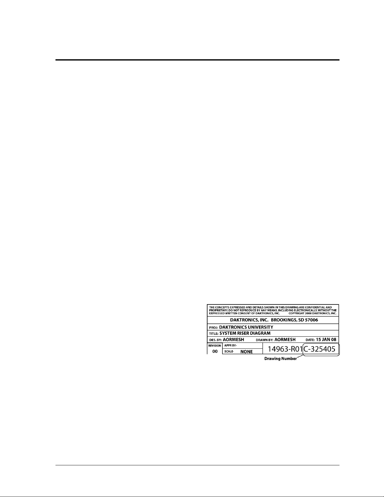
Figure 1: Daktronics Drawing Label
This manual explains the installation, maintenance, and troubleshooting of the TI-2031 and TI-3031
locker room clocks. For additional information regarding the safety, installation, operation, or service
of this system, refer to the telephone numbers listed in Section 4. This manual is not specific to a
particular installation.
Important Safeguards:
Please read and understand all instructions before beginning the installation process.
Do not drop control equipment or allow it to get wet.
Do not disassemble control equipment or electronic controls of the display; failure to
follow this safeguard will make the warranty null and void.
Disconnect display power when not in use or when servicing.
Disconnect display power before servicing power supplies to avoid electrical shock.
Power supplies run on high voltage and may cause physical injury if touched while
powered.
Do not modify the scoreboard structure or attach any panels or coverings to the
scoreboard without the express written consent of Daktronics, Inc.
Project-specific information takes precedence over any other general information found in
this manual.
1.1 Resources
Figure 1 illustrates a Daktronics drawing
label. The drawing number is located in the
lower-right corner of a drawing. This
manual refers to drawings by listing the last
set of digits and the letter preceding them.
In the example, the drawing would be
referred to as Drawing C-325405.
Reference Drawing:
System Riser Diagram ........................................................................... Drawing C-325405
Daktronics identifies manuals by the DD or ED number located on the cover page of each
manual. For example, this manual would be referred to as DD1732287.
The serial and model numbers of a Daktronics scoreboard can be found on the ID label on the
display as shown in Figure 2. Please list the model number, display serial number, and the
date this display became operational in the blanks provided on the second page of this
manual. When calling Daktronics customer service, please have this information available to
ensure the request is serviced as quickly as possible.
Introduction 1
Page 8

Main Component Labels
Part Type
Part Number
Individual circuit board
0P-XXXX-XXXX
Assembly; a collection of circuit boards
0A-XXXX-XXXX
Wire or cable
W-XXXX
Fuse
F-XXXX
Transformer
T-XXXX
Metal part
M-XXX
Fabricated metal assembly
0S-XXXXXX
Specially ordered part
PR-XXXXX-X
Accessory Labels
Component
Label
Termination block for power
or signal cable
TBXX
Grounding point
EXX
Power or signal jack
JXX
Power or signal plug for the
opposite jack
PXX
Model
Control Console
TI-2031
All Sport 5000 Series Control Console Operation Manual (ED-11976)
All Sport 4000 Series Control Console Operation Manual (ED-9999)
All Sport 1600 Series Control Console Operation Manual (ED-12462)
TI-3031
All Sport 5500 Series Control Console Operations Manual (ED-16809)
Figure 2: Scoreboard ID Label
Figure 3: Typical Label
1.2 Daktronics Nomenclature
Most components within this display carry a white label that lists the part number of the unit.
If a component is not found in the Replacement Parts List in Section 3.3, use the label to order
a replacement. Figure 3 illustrates a typical label. The part number is in bold.
Following the Replacement Parts List is the Daktronics Exchange Policy and the Repair &
Return Program. Refer to these instructions if replacing or repairing any display component.
1.3 Control Consoles
Daktronics locker room clocks are typically controlled by the same control console as the
scoreboard(s) in the facility. Refer to Drawing A-102198 for an example of how all the
equipment works together. The locker room clocks are designed for use with All Sport® 1600,
4000, 5000 or 5500 series consoles. Refer to the following manuals for operating instructions:
All manuals are available online at http://www.daktronics.com/manuals.
2 Introduction
Page 9

Section 2: Mechanical & Electrical Installation
The TI-2031 and TI-3031 locker room clocks are equipped with 4" (102 mm) red LED digits. The displays
are connected to the signal from the main scoreboard in the facility and will display the same time that is
shown on the scoreboard.
There are two primary methods of installing these locker room clocks: 1) surface mounted on the wall
with mounting screws or anchors, or 2) flush mounted in the wall between standard spaced 16" studs.
Reference Drawing:
Installation DWG; TI-2031/3031 Locker Room Clock .......................... Drawing B-1064515
2.1 Surface Mount Method
The surface mount cabinet mounts centered over an electrical outlet and uses the deep rear
mounting panel.
1. Drill holes in the wall and install anchors or screws at the locations shown in Drawing
B-1064515. The customer is responsible for providing mounting anchors or screws.
2. Install a 120 V AC, 15 amp electrical outlet or use an existing outlet that is located where
the display will be installed. The outlet should be positioned behind the clock cabinet so
that the wall pack transformer fits in the recessed area of the rear mounting panel.
3. Mount the rear panel on anchor screws and tighten snuggly.
4. Route the signal cable to the clock mounting location and allow it to extend at least 12"
(305 mm) beyond the wall.
5. Connect the signal wire to plug P-1388 signal terminal on the left side of the display
(when viewed from the rear). Connect the red signal wire to the positive (+) jack labeled
“CL-IN” and the white signal wire to the negative (-) jack labeled “CL-IN”.
6. Plug the wall pack transformer into the power jack located below the signal terminal, and
plug the wall pack into the electrical outlet.
7. Line up and mate the rear and front cabinet pieces. Attach the pieces together with
included screws.
Mechanical & Electrical Installation 3
Page 10

2.2 Flush Mount Method
The flush mount cabinet mounts between two 2x4 studs and uses the flush mount rear panel.
1. Drill holes in the wall and install anchors or screws at the locations shown in Drawing
B-1064515. The customer is responsible for providing mounting anchors or screws.
2. Rough out the power supply and signal recess behind cabinet mounting location as
depicted in Drawing B-1064515.
3. Install a 120 V AC, 15 amp electrical outlet on the stud behind the drywall behind the
opening for the clock. This will allow the wall pack transformer to be plugged in and be
out of the way of the clock when the clock is installed in the wall.
4. Route the signal cable to the clock mounting location and allow it to extend at least 12"
(305 mm) beyond the wall.
5. Plug the wall pack transformer into the outlet.
6. Mount the flush-style rear cabinet panel and tighten the anchor screws as needed.
7. Connect the signal wire to plug P-1388 signal terminal on the left side of the display
(when viewed from the rear). Connect the red signal wire to the positive (+) jack labeled
“CL-IN” and the white signal wire to the negative (-) jack labeled “CL-IN”.
8. Plug the wall pack transformer into the power jack located below the signal terminal.
9. Line up and mate the rear and front cabinet pieces. Attach the pieces together with
included screws.
4 Mechanical & Electrical Installation
Page 11

Section 3: Maintenance & Troubleshooting
Connector #
Function
J2
Power Input
TB1
Signal in and out
Description
Daktronics Part #
AS5K 4 Col Clock w/ Driver
0P-1150-0259
Transformer; 12 V AC
T-1118
IMPORTANT NOTES:
1. Disconnect power before doing any repair or maintenance work on the display.
2. Permit only qualified service personnel to access internal display electronics.
3. Disconnect power when not using the display.
3.1 Component Access
To gain access to the internal components of the display (surface mount):
1. Remove top and bottom screws connecting front and rear cabinet.
2. Separate the front and rear cabinet pieces.
3. Unplug both the signal and power wires from the rear of the display.
4. Remove screws holding circuit board to front of the cabinet.
3.2 LED Drivers
The LED driver performs the task of switching digits on and off. Locker room clock drivers
contain all four LED digits together in one assembly. Locker room clock drivers have two
connectors that provide power and signal to and from the driver:
3.3 Replacement Parts
Refer to the following table for replacement parts.
Maintenance & Troubleshooting 5
Page 12

Symptom/Condition
Possible Cause
Display will not light
Console not connected or poor connection
No power to the control console
No power to the display
Loose incoming signal terminal at the display
Garbled display
Control console malfunction
Driver malfunction
Digit will not light
Driver malfunction
Segment will not light or
stays lit
Driver malfunction
3.4 Troubleshooting
This section lists potential problems with the display and indicates possible causes. This list
does not include every possible problem, but does represent some of the more common
situations that may occur.
6 Maintenance & Troubleshooting
Page 13

Section 4: Daktronics Exchange and Repair &
Market Description
Customer Service Number
Schools (including community/junior colleges), religious
organizations, municipal clubs and community centers
877-605-1115
Universities and professional sporting events, live events
for auditoriums and arenas
866-343-6018
Return Programs
4.1 Exchange Program
The Daktronics Exchange Program is a service for quickly replacing key components in need
of repair. If a component fails, Daktronics sends a replacement part to the customer who, in
turn, returns the failed component to Daktronics. This decreases equipment downtime.
Customers who follow the program guidelines explained below will receive this service.
Before Contacting Daktronics
Identify these important numbers:
Display Serial Number: _________________________________________________________
Display Model Number: _________________________________________________________
Job/Contract Number: __________________________________________________________
Date Installed: _________________________________________________________________
Daktronics Customer ID Number: ________________________________________________
To participate in the Exchange Program, follow these steps:
1. Call Daktronics Customer Service.
2. When the exchange part is received, mail the old part to Daktronics.
If the replacement part fixes the problem, send in the problem part being replaced.
a. Package the old part in the same shipping materials in which the replacement
part arrived.
b. Fill out and attach the enclosed UPS shipping document.
c. Ship the part to Daktronics.
3. The defective or unused parts must be returned to Daktronics within 5 weeks of
initial order shipment.
If any part is not returned within five (5) weeks, a non-refundable invoice will be
presented to the customer for the costs of replenishing the exchange parts inventory
with a new part.
Daktronics reserves the right to refuse parts that have been damaged due to acts of
nature or causes other than normal wear and tear.
Daktronics Exchange and Repair & Return Programs 7
Page 14

4.2 Repair & Return Program
For items not subject to exchange, Daktronics offers a Repair & Return Program. To send a
part for repair, follow these steps:
1. Call or fax Daktronics Customer Service:
Refer to the appropriate market phone number in the chart on the previous page.
Fax: 605-697-4444
2. Receive a case number before shipping.
This expedites repair of the part.
3. Package and pad the item carefully to prevent damage during shipment.
Electronic components, such as printed circuit boards, should be placed in an
antistatic bag before boxing. Daktronics does not recommend using packing „peanuts‟
when shipping.
4. Enclose:
name
address
phone number
the case number
a clear description of symptoms
Shipping Address
Daktronics Customer Service
[Case #]
201 Daktronics Drive, Dock E
Brookings, SD 57006
4.3 Daktronics Warranty and Limitation of Liability
The Daktronics Warranty and Limitation of Liability is located in Appendix B. The Warranty
is independent of Extended Service agreements and is the authority in matters of service,
repair, and display operation.
8 Daktronics Exchange and Repair & Return Programs
Page 15

Appendix A: Reference Drawings
Riser Diagram: A/S 5000 Series High End System ................................................... Drawing A-102198
Installation DWG; TI-2031/3031 Locker Room Clock.............................................. Drawing B-1064515
Reference Drawings 9
Page 16

Page 17

Page 18

Page 19

Appendix B: Daktronics Warranty and Limitation
of Liability
Daktronics Warranty and Limitation of Liability 11
Page 20

Page 21

Copyright © Daktronics, Inc. SL-02374 Rev 10 02-Mar-2009 Page 1 of 2
DAKTRONICS
WARRANTY AND LIMITATION OF LIABILITY
This Warranty and Limitation of Liability (the “Warranty”) sets forth the warranty provided by Daktronics with respect to the Equipment. By
accepting delivery of the Equipment, Purchaser agrees to be bound by and accept these terms and conditions. All defined terms within
the Warranty shall have the same meaning and definition as provided elsewhere in the Agreement.
DAKTRONICS WILL ONLY BE OBLIGATED TO HONOR THE WARRANTY SET FORTH IN THESE TERMS AND CONDITIONS UPON RECEIPT OF FULL
PAYMENT FOR THE EQUIPMENT.
1. Warranty Coverage
2. Exclusion from Warranty Coverage
A. Daktronics warrants to the original end-user that the Equipment will be free from Defects (as defined below) in materials and
workmanship for a period of one (1) year (the “Warranty Period”). The warranty period shall commence on the earlier of: (i) four
weeks from the date that the equipment leaves Daktronics’ facility; or (ii) Substantial Completion as defined herein. The warranty
period shall expire on the first anniversary of the commencement date.
“Substantial Completion” means the operational availability of the Equipment to the Purchaser in accordance with the
Equipment’s specifications, without regard to punch-list items, or other non-substantial items which do not affect the operation of
the Equipment.
B. Daktronics’ obligation under this Warranty is limited to, at Daktronics’ option, replacing or repairing, any Equipment or part
thereof that is found by Daktronics not to conform to the Equipment’s specifications. Unless otherwise directed by Daktronics,
any defective part or component shall be returned to Daktronics for repair or replacement. Daktronics may, at its option,
provide on-site warranty service. Daktronics shall have a reasonable period of time to make such replacements or repairs and
all labor associated therewith shall be performed during regular working hours. Regular working hours are Monday through
Friday between 8:00 a.m. and 5:00 p.m. at the location where labor is performed, excluding any holidays observed by either
Purchaser or Daktronics.
C. Daktronics shall pay ground transportation charges for the return of any defective component of the Equipment. If returned
Equipment is repaired or replaced under the terms of this warranty, Daktronics will prepay ground transportation charges back to
Purchaser; otherwise, Purchaser shall pay transportation charges to return the Equipment back to the Purchaser. All returns must
be pre-approved by Daktronics before shipment. Daktronics shall not be obligated to pay freight for any unapproved return.
Purchaser shall pay any upgraded or expedited transportation charges.
D. Any replacement parts or Equipment will be new or serviceably used, comparable in function and performance to the
original part or Equipment, and warranted for the remainder of the Warranty Period. Purchasing additional parts or Equipment
from the Seller does not extend this Warranty Period.
E. Defects shall be defined as follows. With regard to the Equipment (excepting LEDs), a “Defect” shall refer to a material
variance from the design specifications that prohibit the Equipment from operating for its intended use. With respect to LEDs,
“Defects” are defined as LED pixels that cease to emit light. The limited warranty provided by Daktronics does not impose any
duty or liability upon Daktronics for partial LED pixel degradation. Nor does the limited warranty provide for the replacement or
installation of communication methods including but not limited to, wire, fiber optic cable, conduit, trenching, or for the purpose
of overcoming local site interference radio equipment substitutions.
THIS LIMITED WARRANTY IS THE ONLY WARRANTY APPLICABLE TO THE EQUIPMENT AND REPLACES ALL OTHER WARRANTIES OR
CONDITIONS, EXPRESS OR IMPLIED, INCLUDING, BUT NOT LIMITED TO, THE IMPLIED WARRANTIES OR CONDITIONS OF
MERCHANTABILITY AND FITNESS FOR A PARTICULAR PURPOSE. SPECIFICALLY, EXCEPT AS PROVIDED HEREIN, THE SELLER
UNDERTAKES NO RESPONSIBILITY FOR THE QUALITY OF THE EQUIPMENT OR THAT THE EQUIPMENT WILL BE FIT FOR ANY PARTICULAR
PURPOSE FOR WHICH PURCHASER MAY BE BUYING THE EQUIPMENT. ANY IMPLIED WARRANTY IS LIMITED IN DURATION TO THE
WARRANTY PERIOD. NO ORAL OR WRITTEN INFORMATION, OR ADVICE GIVEN BY THE COMPANY, ITS AGENTS OR EMPLOYEES,
SHALL CREATE A WARRANTY OR IN ANY WAY INCREASE THE SCOPE OF THIS LIMITED WARRANTY.
THIS LIMITED WARRANTY IS NOT TRANSFERABLE.
The limited warranty provided by Daktronics does not impose any duty or liability upon Daktronics for:
A Any damage occurring, at any time, during shipment of Equipment unless otherwise provided for in the Agreement. When
returning Equipment to Daktronics for repair or replacement, Purchaser assumes all risk of loss or damage, and agrees to use
any shipping containers that might be provided by Daktronics and to ship the Equipment in the manner prescribed by
Daktronics;
B. Any damage caused by the unauthorized adjustment, repair or service of the Equipment by anyone other than personnel of
Daktronics or its authorized repair agents;
Page 22

Copyright © Daktronics, Inc. SL-02374 Rev 10 02-Mar-2009 Page 2 of 2
C. Damage caused by the failure to provide a continuously suitable environment, including, but not limited to: (i) neglect or
misuse, (ii) a failure or sudden surge of electrical power, (iii) improper air conditioning or humidity control, or (iv) any other cause
other than ordinary use;
D. Damage caused by fire, flood, earthquake, water, wind, lightning or other natural disaster, strike, inability to obtain materials
or utilities, war, terrorism, civil disturbance or any other cause beyond Daktronics’ reasonable control;
E. Failure to adjust, repair or replace any item of Equipment if it would be impractical for Daktronics personnel to do so because
of connection of the Equipment by mechanical or electrical means to another device not supplied by Daktronics, or the
existence of general environmental conditions at the site that pose a danger to Daktronics personnel;
F. Any statements made about the product by salesmen, dealers, distributors or agents, unless such statements are in a written
document signed by an officer of Daktronics. Such statements as are not included in a signed writing do not constitute
warranties, shall not be relied upon by Purchaser and are not part of the contract of sale;
G. Any damage arising from the use of Daktronics products in any application other than the commercial and industrial
applications for which they are intended, unless, upon request, such use is specifically approved in writing by Daktronics; or
H. Any performance of preventive maintenance.
3. Limitation of Liability
4. Assignment of Rights
5. Dispute Resolution
6. Governing Law
7. Availability of Extended Service Agreement
Daktronics shall be under no obligation to furnish continued service under this Warranty if alterations are made to the Equipment
without the prior written approval of Daktronics.
It is specifically agreed that the price of the Equipment is based upon the following limitation of liability. In no event shall
Daktronics (including its subsidiaries, affiliates, officers, directors, employees, or agents) be liable for any special, consequential,
incidental or exemplary damages arising out of or in any way connected with the Equipment or otherwise, including but not
limited to damages for lost profits, cost of substitute or replacement equipment, down time, lost data, injury to property or any
damages or sums paid by Purchaser to third parties, even if Daktronics has been advised of the possibility of such damages. The
foregoing limitation of liability shall apply whether any claim is based upon principles of contract, tort or statutory duty, principles
of indemnity or contribution, or otherwise.
In no event shall Daktronics be liable to Purchaser or any other party for loss, damage, or injury of any kind or nature arising out of
or in connection with this Warranty in excess of the purchase price of the Equipment actually delivered to and paid for by the
Purchaser. The Purchaser’s remedy in any dispute under this Warranty shall be ultimately limited to the Purchase Price of the
Equipment to the extent the Purchase Price has been paid.
The Warranty contained herein extends only to the original end-user (which may be the Purchaser) of the Equipment and no
attempt to extend the Warranty to any subsequent user-transferee of the Equipment shall be valid or enforceable without the
express written consent of Daktronics.
Any dispute between the parties will be resolved exclusively and finally by arbitration administered by the American Arbitration
Association (“AAA”) and conducted under its rules, except as otherwise provided below. The arbitration will be conducted
before a single arbitrator. The arbitration shall be held in Brookings, South Dakota. Any decision rendered in such arbitration
proceedings will be final and binding on each of the parties, and judgment may be entered thereon in any court of competent
jurisdiction. This arbitration agreement is made pursuant to a transaction involving interstate commerce, and shall be governed
by the Federal Arbitration Act.
The rights and obligations of the parties under this warranty shall not be governed by the provisions of the United Nations
Convention on Contracts for the International Sales of Goods of 1980. Both parties consent to the application of the laws of the
State of South Dakota to govern, interpret, and enforce all of Purchaser and Daktronics rights, duties, and obligations arising
from, or relating in any manner to, the subject matter of this Warranty, without regard to conflict of law principles.
For Purchaser’s protection, in addition to that afforded by the warranties set forth herein, Purchaser may purchase extended
warranty services to cover the Equipment. The Extended Service Agreement, available from Daktronics, provides for electronic
parts repair and/or on-site labor for an extended period from the date of expiration of this warranty. Alternatively, an Extended
Service Agreement may be purchased in conjunction with this warranty for extended additional services. For further information,
contact Daktronics Customer Service at 1-800-DAKTRONics (1-800-325-8766).
 Loading...