

Page 1

201 Daktronics Drive PO Box 5128 Brookings, SD 57006-5128
Tel: 1-800-DAKTRONICS (1-800-325-8766) Fax: 605-697-4700
Web: www.daktronics.com Email: helpdesk@daktronics.com
Daktronics T-7000 Series
Touchpads
Installation & Maintenance Manual
DD1953274 Rev 1 – 4 March 2011
Models
T-7060
FT-7150
T-7078
FT-7190
T-7096
FT-7190T
FT-7240T
Page 2

Page 3

Please fill in the information below to use for reference when calling Daktronics for assistance.
Touchpad 1
Date _______________________________
Serial #_____________________________
Touchpad 2
Date _______________________________
Serial #_____________________________
Touchpad 3
Date _______________________________
Serial #_____________________________
Touchpad 4
Date _______________________________
Serial #_____________________________
Touchpad 5
Date _______________________________
Serial #_____________________________
Touchpad 6
Date _______________________________
Serial #_____________________________
Touchpad 7
Date _______________________________
Serial #_____________________________
Touchpad 8
Date _______________________________
Serial #_____________________________
Touchpad 9
Date _______________________________
Serial #_____________________________
Touchpad 10
Date _______________________________
Serial #_____________________________
Touchpad 11
Date _______________________________
Serial # ____________________________
Touchpad 12
Date _______________________________
Serial # ____________________________
Touchpad 13
Date _______________________________
Serial # ____________________________
Touchpad 14
Date _______________________________
Serial # ____________________________
Touchpad 15
Date _______________________________
Serial # ____________________________
Touchpad 16
Date _______________________________
Serial # ____________________________
Touchpad 17
Date _______________________________
Serial # ____________________________
Touchpad 18
Date _______________________________
Serial # ____________________________
Touchpad 19
Date _______________________________
Serial # ____________________________
Touchpad 20
Date _______________________________
Serial # ____________________________
DAKTRONICS, INC.
Copyright 2011
All rights reserved. While every precaution has been taken in the preparation of this manual, the publisher
assumes no responsibility for errors or omissions. No part of this book covered by the copyrights hereon may be
reproduced or copied in any form or by any means – graphic, electronic, or mechanical, including photocopying,
taping, or information storage and retrieval systems – without written permission of the publisher.
OmniSport® is a trademark of Daktronics, Inc. All other trademarks in this manual are the property of their
respective owners.
DD1953274
Product 1040
Rev 1 – 4 March 2011
Page 4

Page 5

Table of Contents
Section 1: Introduction ............................................................................................................................ 1
1.1 Controllers ................................................................................................................................ 1
1.2 Touchpad Identification ......................................................................................................... 1
Specifications .................................................................................................................... 2
1.3 Resources .................................................................................................................................. 2
Section 2: Mechanical Installation ........................................................................................................ 3
2.1 Touchpad Installation ............................................................................................................. 3
Section 3: Connections............................................................................................................................. 5
3.1 Deck Cabling and Lane Modules .......................................................................................... 5
3.2 Functional Test ........................................................................................................................ 6
Section 4: Maintenance & Troubleshooting ........................................................................................ 7
4.1 Basic Maintenance of Timing System ................................................................................... 7
4.2 Touchpad Cleaning ................................................................................................................. 7
4.3 Inspection Procedure .............................................................................................................. 8
4.4 Advanced Touchpad Troubleshooting ................................................................................ 8
4.5 Side & Bottom Vinyl Edge Cover Replacement ................................................................ 11
4.6 Cable Replacement................................................................................................................ 14
4.7 Replacement Parts ................................................................................................................. 18
4.8 Aquatics Systems Warranty and Limitation of Liability ................................................. 18
Section 5: Contact Information ............................................................................................................ 19
Appendix A: Aquatics Systems Warranty and Limitation of Liability .............................................. 21
Table of Contents i
Page 6

Page 7
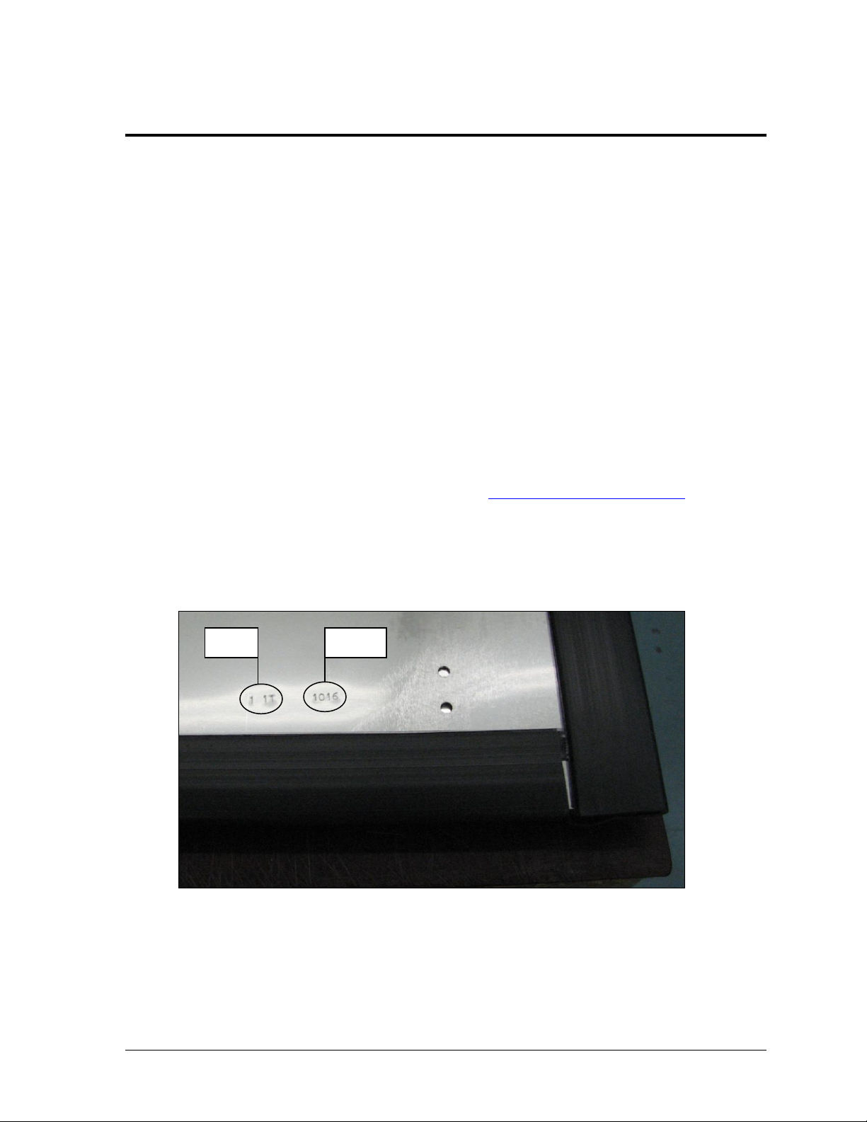
Figure 1: ID Stamp
Date
Serial #
Section 1: Introduction
This manual explains the installation of Daktronics T-7000 series touchpads and provides details for
maintenance and troubleshooting. For additional information regarding the safety, installation,
operation, or service of this system, refer to the contact information listed in Section 5.
This manual is not specific to a particular installation. Project-specific information takes precedence
over any other general information found in this manual.
Please read and understand all instructions before beginning the installation process.
1.1 Controllers
Daktronics touchpads are typically used with an OmniSport® 2000 timing system. The
OmniSport 2000 timer uses keyboard overlays (sport inserts) to control numerous sports and
scoreboard models. Refer to the following manual for operating instructions:
OmniSport 2000 Timing Console Operations Manual (ED-13312)
This control console manual is available online at www.daktronics.com/manuals.
1.2 Touchpad Identification
A date (month / year) and serial number can be found stamped in the lower-right corner of
the rear of the touchpad as shown in Figure 1.
Please list the date and serial number for each touchpad in the system in the blanks provided
on the second page of this manual. When calling Daktronics customer service, please have
this information available to ensure the request is serviced as quickly as possible.
Introduction 1
Page 8

Model
Dimensions:
Height, Width, Depth (of top flange)
Weight
T-7060
H 1'-10", W 5'-0", D 2.8"
(559 mm, 1524 mm, 71 mm)
28.25 lb
(12.8 kg)
T-7078
H 1'-10", W 6'-6", D 2.8"
(559 mm, 1981 mm, 71 mm)
37.5 lb
(17 kg)
T-7096
H 2'-0", W 8'-0", D 2.8"
(610 mm, 2438 mm, 71 mm)
50 lb
(22.7 kg)
FT-7150
H 3'-0", W 5'-0", D 2"
(914 mm, 1524 mm, 51 mm)
44.7 lb
(20.3 kg)
FT-7190
H 3'-0", W 6'-3", D 2"
(914 mm, 1905 mm, 51 mm)
56.8 lb
(25.8 kg)
FT-7190T
H 3'-0", W 6'-3", D 3.9"
(914 mm, 1905 mm, 99 mm)
57 lb
(25.9 kg)
FT-7240T
H 3'-0", W 7'-11", D 3.9"
(914 mm, 2413 mm, 99 mm)
72.5 lb
(32.9 kg)
Specifications
Note: All touchpad models have a thickness of 0.3" (8 mm).
1.3 Resources
Daktronics identifies manuals by the DD or ED number located on the cover page of each
manual. For example, this manual would be referred to as DD1953274.
2 Introduction
Page 9
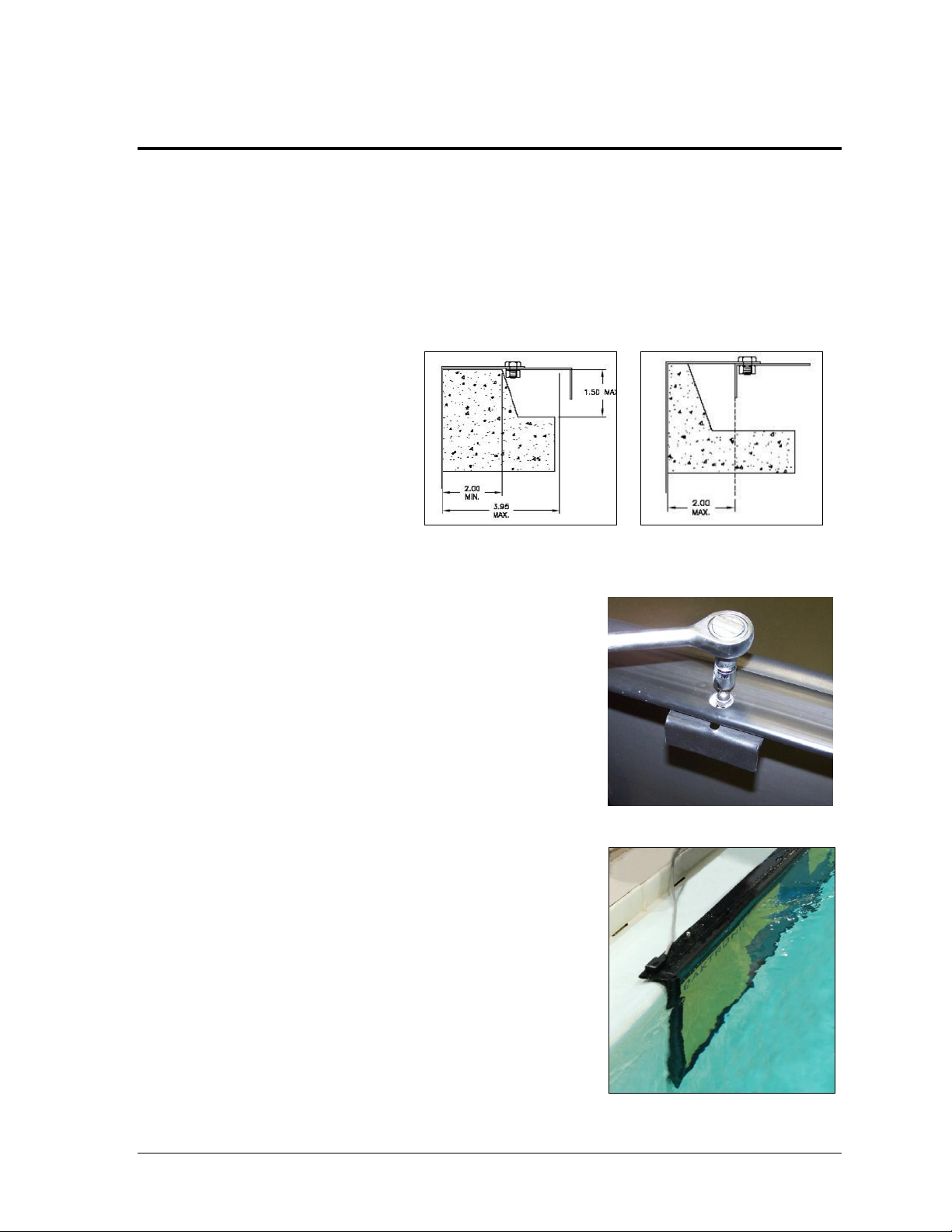
Figure 2: Universal Bracket for
Wider Gutter Lip
Figure 3: Universal Bracket for
Narrow Gutter Lip
Figure 4: Securing the Bracket
Figure 5: Touchpad Next to Wall
Section 2: Mechanical Installation
2.1 Touchpad Installation
1. Before the meet, install the touchpads in the pool. With one person on each end of the
touchpad, carefully lower the touchpad into the pool. Center the touchpad in the lane.
Secure the supplied adjustable bracket to the pool gutter. If the pool does not have a
gutter, secure the touchpad by running a cord through the holes on top of the touchpad
and tying it to the starting block.
2. The universal bracket
adjusts to both a narrow or
wider gutter lip. (Figure 2
and Figure 3).
3. Use a 7/16" socket wrench to secure the brackets in
place on the touchpad (Figure 4).
4. A Daktronics touchpad is designed to fill with water
to aid in its stabilization. When properly installed, the
touchpad should “hug” the pool wall (Figure 5).
5. Connect the touchpads to the lane modules or deck
plates. Read and follow instructions in Section 3.
Do not allow swimmers to use paddles, fins or kick
boards with touchpads in the pool!
Mechanical Installation 3
Page 10

Figure 6: Touchpad with Spacers
If the pool wall has obstructions or the gutter protrudes from the wall, use spacers (PVC
board may be cut in strips) to create a stable support for the touchpad (Figure 6). Spacer size
is determined by the height and the extra depth required. Use 3M™ VHB™ Tape 5930
(Daktronics part number AT-1089 [¾"]) to adhere the spacers to the touchpad.
Ensure the spacers do not cover the drainage holes on the back of the touchpad!
Note: Daktronics does not provide these spacers.
For more information on the care and maintenance of touchpads, refer to Section 4.
4 Mechanical Installation
Page 11

Figure 7: Insert GND Side to Black
Female Jack
Figure 8: Daktronics Lane Module
Figure 9: Individual Lane Deck Plate
Section 3: Connections
3.1 Deck Cabling and Lane Modules
Always place cables and equipment in areas of minimal
traffic. Cover wires and cables with a mat to prevent
accidents. Figure 7 illustrates an important detail to
always remember when plugging dual banana
connectors. The GND (ground) tab on the plug must
line up with the black female jack for the timing
system to work.
If some touchpads are connected backwards and some
connected correctly, it may cause touchpads to register
times when the pad has not been touched.
For an On-Deck System, connect the plug from
the touchpad to the TOUCHPAD jack on a lane
module (Figure 8).
After the system has been completely set up,
test each touchpad (refer to Section 3.2).
For an In-Deck System, connect the plug from the
touchpad into the TP jack on the lane deck plate
(Figure 9).
After the system has been completely set up, test
each touchpad (refer to Section 3.2).
For more information about any additional input device connections and connecting to the
OmniSport 2000 timer, refer to the OmniSport 2000 Timing Console Operations Manual
(ED-13312).
This control console manual is available online at www.daktronics.com/manuals.
Electrical Installation 5
Page 12

3.2 Functional Test
1. Plug the touchpad into the touchpad input on the lane module or deck plate. Make sure
that the GND tab on the touchpad connector is lined up with the black jack on the lane
module/deck plate touchpad input.
2. Make sure that the lane modules/deck plates are connected to the OmniSport 2000
console and the console is powered on.
3. Enter the swimming mode of the OmniSport 2000 console and select Menu 5, then 2 to
display the lane data test menu. When the touchpad is pressed, a “T” should flash for 2
seconds in the lane corresponding to the touchpad.
4. With the touchpad hanging in place on the pool wall, bend down and with an open hand,
touch the touchpad with just finger tips. Do this by brining the hand in with the same
amount of energy a swimmer in the water would have. If this is done too lightly, or to
slowly, expect that a touch may not register. Also, because the touchpad needs to charge
back up, count “1001, 1002, 1003” before touching again.
5. Watching the lane data test screen, repeat this test across the entire touchpad surface,
from left to right and top to bottom. This will ensure that there are no dead spots in the
touchpad.
6 Electrical Installation
Page 13

Figure 10: Touchpad cart
Section 4: Maintenance & Troubleshooting
IMPORTANT NOTES:
1. Always disconnect the touchpad, remove it from the water, and allow it to dry before doing
any repair work.
2. Disconnect touchpad and remove it from water when not in use.
4.1 Basic Maintenance of Timing System
After each meet, it is crucial to follow these basic maintenance procedures to ensure the
longevity of the timing equipment.
Turn off the power to all equipment associated with the system.
When the system is set up for an event, touchpads should be removed from the water
every 48 hours, inspected, and allowed to dry for 6 hours.
o Inspect the cable and connector for nicks, cuts, and corrosion. Use the brush
provided in the maintenance kit to remove any corrosion from the banana
connections. After cleaning, apply silicone grease to the connectors. Replace cable
if necessary (refer to Section 4.6).
o Verify that all edge protectors are securely in place. Replace edge protectors if
necessary (refer to Section 4.5).
o Verify the boot along the top front bend is not cut.
o Refer to Section 4.3 for additional inspection procedures.
At the end of each meet, remove the
touchpads from the pool, place them onto
their storage cart (Figure 10). Store
touchpads in a room outside of the pool
environment and chemicals. Recommended
temperatures in storage area should range
between 33°F and 90° F (55° C and 32.2° C)
with adequate fresh air circulation.
4.2 Touchpad Cleaning
Maintenance & Troubleshooting 7
After each meet, rinse the touchpad with non-chlorinated tap water. If possible the touchpad
should be submerged in a tank of fresh water, otherwise use a hose or pour buckets of water
onto the touchpad.
DO NOT use a pressure washer.
DO NOT use treated pool water.
Page 14

Problem
Possible Cause
Solution/Items to Check
Voltage measured on the
banana plug of the touchpad
cable when it is plugged into
the lane module or deck
plate is 0 V DC or close to it
Bad connection between the
banana plug and the lane
module (on-deck) or
deck plate (in-deck)
1) Clean both the male banana
plug on the touchpad cable and
the female jack on the lane
module or deck plate.
2) Using a small straight screw
driver, bow out the center of
each of the 4 leafs on the male
banana pin so that it provides
more pressure on the contact
when the banana plug is
inserted into the lane module or
deck plate (see Figure 11).
3) If cleaning the connections
doesn’t resolve the problem,
check the next Possible Cause.
4.3 Inspection Procedure
Visually inspect:
Banana plug for corrosion – if corrosion is found, refer to Section 4.6
Cable for cuts – if cuts are found, refer to Section 4.6
All edge protectors are securely in place
Rubber boot across the top of the touchpad is not ripped/torn and is adhered in place
Non-slip surface on the face of the touchpad is not cut, torn or peeling
The touchpad is not delaminating. This will be evident if the face of the touchpad
looks like it is ballooning, with big bubbles (6 + inches in diameter) or when pressed,
it is loose.
For sharp edges; remove any sharp edges with a file
Touchpad brackets are adjusted correctly for the gutter type
Touchpad is flat against the pool wall, with no water inlets or other obstructions
between the touchpad and the wall
4.4 Advanced Touchpad Troubleshooting
1. Plug the touchpad into the touchpad input on the lane module or deck plate. Make sure
that the GND tab on the touchpad connector is lined up with the black jack on the lane
module/deck plate touchpad input.
2. Make sure that the lane modules/deck plates are connected to the OmniSport 2000
console and that the console is powered on and in swimming mode.
3. Using a DC voltmeter, connect the red probe to the positive connector of the touchpad,
and connect the black probe to the GND connector of the touchpad.
With the touchpad installed and not being pressed, 0.25 V DC should be measured.
When the touchpad is pressed, the voltage should drop to approximately 0 V DC.
When the press is released, the voltage should start climbing for approximately 1.5 -
If the readings are different from those described above, use the following table to
determine the possible cause and solution. If a problem occurs that is not listed or that
cannot be resolved, contact Daktronics using the information provided in Section 5.
8 Maintenance & Troubleshooting
3 seconds and level out at 0.25 V DC again.
Page 15

Problem
Possible Cause
Solution/Items to Check
On-deck:
Bad lane module input
1) Disconnect the touchpad from
the lane module and clean the
connections if not already
performed.
2) Measure the voltage between
the red and black connectors on
the TOUCHPAD input of the
lane module:
If the voltage is 0 V DC, the
touchpad input on the lane
module is probably bad.
Swap the module with one
known to work correctly to
verify. Contact Daktronics
to order a replacement lane
module if needed.
If the voltage is 0.25 V DC,
it is probably a shorted
touchpad. Refer to Possible
Cause: Shorted Touchpad.
In-deck:
High resistance in the cable
between the deck plate and
lane interface, the termination
of the cable to the green
phoenix connector, the mating
of the green phoenix
connector onto the lane
interface, or a bad touchpad
input on the lane interface
With the touchpad connected,
use a voltmeter to measure V
DC on pins 1 and 5 of the green
phoenix connector. If the
reading is 0.25 V DC at the lane
interface and 0 V DC at the
deck plate, there is a break or
high resistance in the cabling or
termination of the cable to the
phoenix connector.
With the touchpad
disconnected, use a voltmeter
to measure V DC on pins 1 and
5 of the green phoenix
connector. If the reading is 0 V
DC or close to it, it is probably
corrosion between the green
phoenix connector and the lane
interface, or a bad touchpad
input on the lane interface.
In either instance, contact
Daktronics using the information
provided in Section 5.
Shorted Touchpad
If a shorted touchpad is suspected,
Contact Daktronics using the
information provided in Section 5.
Maintenance & Troubleshooting 9
Page 16

Problem
Possible Cause
Solution/Items to Check
Touchpad is not registering
a touch, and the voltage
stays at 0.25 V DC when the
touchpad is pressed
Bad touchpad cable
1) Unplug the touchpad from the
lane module/deck plate.
2) Set the meter to continuity.
3) Touch the red probe of the
meter to the GND tab of the
touchpad connector, and touch
the black probe of the meter to
the back sheet of the touchpad.
The meter should read 0 ohms.
If it is open, the cable is bad.
4) Next touch the red probe
against the positive connector of
the touchpad and touch the
black probe to the center sheet
of the touchpad (accessed
through one of the drain holes
on the back side of the
touchpad). The meter should
read 0 ohms. If there is no
continuity, the cable is bad.
5) Refer to Section 4.6 to replace
the bad touchpad cable.
Figure 11: Bowing Banana Plug Pins
10 Maintenance & Troubleshooting
Page 17

Figure 12: Removing Old Tape
Figure 13: Cleaning Edge Protector
Figure 14: Marking Touchpad
4.5 Side & Bottom Vinyl Edge Cover Replacement
1. Remove any remaining tape/adhesive residue from front and back surfaces of touchpad.
Note: Stretch the tape along its length to easily remove (Figure 12).
2. Clean areas where tape was removed with 70/30 Isopropyl alcohol (Figure 13).
3. Snap a new vinyl edge cover onto the touchpad.
a. Using the vinyl edge cover as a guide, use a pencil to make a reference mark along
the entire length of the back of the touchpad (Figure 14). This will be used as a
reference for applying new tape on the back surface.
b. Remove the vinyl edge cover from the touchpad for now.
Maintenance & Troubleshooting 11
Page 18

Figure 15: Applying & Cutting New Tape (Rear)
Figure 16: Applying & Cutting New Tape (Front)
Figure 17: Folding Tape Over Edge Protector
Figure 18: Securing Tape
Pencil Line along
This Edge of Tape
4. Apply supplied double-sided tape to back surface of touchpad along the line that was
just made and cut to length. Ensure the tape is lined up between the pencil line and the
outside edge of the touchpad (Figure 15).
5. Apply supplied double-sided tape to front surface of touchpad on the raised portion of
the stainless steel edge protector and cut to length (Figure 16).
6. Fold tape over the raised portion of stainless steel edge protector (Figure 17).
7. Apply firm finger pressure to the tape on both front and back surfaces across entire
length to ensure proper adhesion (Figure 18).
12 Maintenance & Troubleshooting
Page 19
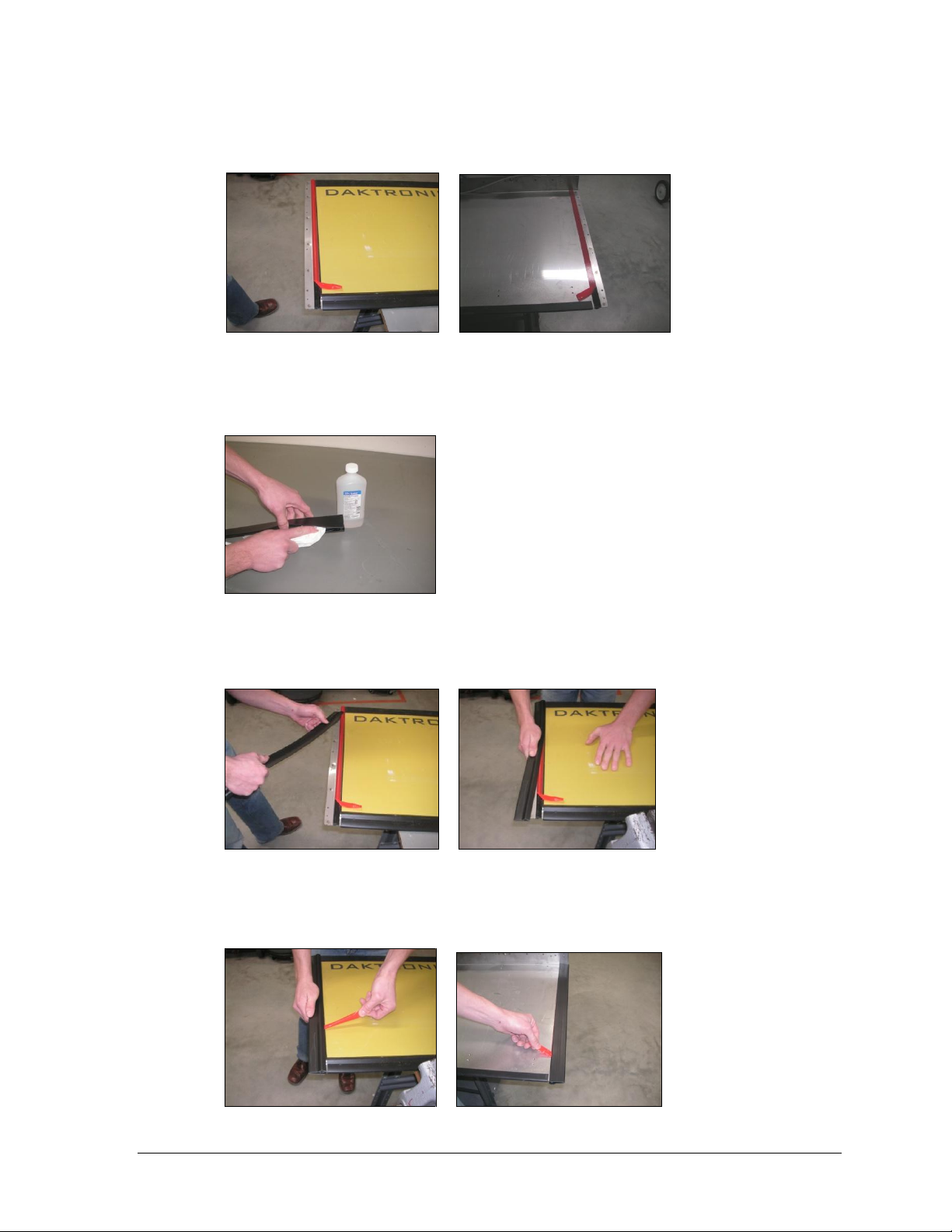
Figure 19: Partially-Peeled Tape Liner
Figure 20: Cleaning Vinyl Edge Cover
Figure 21: Applying Vinyl Edge Cover
Figure 22: Removing Tape Liner
8. Partially peel back tape liner on both front and back surfaces and fold over towards the
center of the touchpad (Figure 19).
9. Clean the inside of the vinyl edge cover with 70/30 Isopropyl alcohol (Figure 20). Allow
the vinyl edge cover to dry before proceeding.
10. Place the vinyl edge cover back on the touchpad by first inserting the corner on the
touchpad, and then continue pushing along its length (Figure 21).
11. Once the vinyl edge cover is fully seated on the touchpad, peel off the remaining tape
liner on both front and back surfaces (Figure 22).
Maintenance & Troubleshooting 13
Page 20

Figure 23: Securing Vinyl Edge Cover
Figure 24: Top & Bottom Rear View of Touchpad
Figure 25: Removing Four Corner Screws
12. After tape liner has been completely removed, apply firm finger pressure to both the
front and back surfaces of the vinyl edge cover to ensure proper adhesion (Figure 23).
13. Repeat steps 1-12 for all vinyl edge covers that need replacing.
4.6 Cable Replacement
If the control cable develops cuts or it has been determined that it has gone bad, it must be
replaced. Follow the steps below.
1. When viewing the touchpad from the rear, locate the black box on the right-hand side
where the input cable is connected. On the underside of this box are 5 screws (Figure 24).
2. Use a screwdriver to remove the 4 corner screws only (Figure 25).
14 Maintenance & Troubleshooting
Page 21

Figure 26: Lifting Box Away from Touchpad
Figure 27: Removing Black (Ground) Wire
Figure 28: Removing Red (Positive) Wire
3. Carefully turn and lift the box away from the touchpad (Figure 26).
4. The remaining screw on the underside of the touchpad is securing the black (ground)
wire. Remove this wire using a screwdriver and ¼" nut driver (Figure 27).
5. Remove the red (positive) wire from the metal tab with a screwdriver; the box and cable
will be free from the touchpad (Figure 28).
Note: Be careful once the box is removed as the exposed stainless steel tabs can be sharp.
Maintenance & Troubleshooting 15
Page 22

Figure 29: Attaching Black (Ground) Wire
Figure 30: Proper Cable Position
Figure 31: Attaching Red (Positive) Wire
6. Attach the black (ground) wire from the replacement cable first.
a. Hang the cable off the right side of the touchpad.
b. Push the grounding screw up from the bottom side of the touchpad.
c. Place the black (ground) wire terminal ring over the screw, followed by the lock
washer and nut.
d. Tighten with a screwdriver and ¼" nut driver (Figure 29).
e. Swing the cable over to the left side of the touchpad so that the black (ground) wire is
now bent in half (Figure 30).
7. Place the box back on top of the touchpad. Bring the screw through the red (positive)
wire terminal ring, then the metal tabs, and secure to the box (Figure 31).
16 Maintenance & Troubleshooting
Page 23

Figure 32: Proper Rubber Boot Position
Figure 33: Folding Box into Position
Figure 34: Securing Box to Touchpad
8. Slide the rubber boot on the cable up into position and ensure the groove in the boot is
firmly seated into the rounded collar of the box (Figure 32).
9. Fold the box down onto the metal surface of the touchpad (Figure 33).
10. On the underside of the box, start the two left screws first, and then start the two right
screws. Tighten the screws in the same order (Figure 34).
Maintenance & Troubleshooting 17
Page 24

Description
Daktronics Part #
Touchpad Cable Replacement Kit
0A-1040-0115
OmniSport 2000 Maintenance Kit
0A-1240-0003
Side/Bottom Edge Cover Replacement; T-7060
0A-1040-0117
Side/Bottom Edge Cover Replacement; T-7078
0A-1040-0118
Side/Bottom Edge Cover Replacement; T-7096
0A-1040-0119
Side/Bottom Edge Cover Replacement; FT-7150
0A-1040-0120
Side/Bottom Edge Cover Replacement; FT-7190
0A-1040-0121
Side/Bottom Edge Cover Replacement; FT-7240
0A-1040-0122
Tape, VHB, 5930, ¼"
AT-1087
Tape, VHB, 5930, ½"
AT-1088
Tape, VHB, 5930, ¾"
AT-1089
4.7 Replacement Parts
Refer to the following table for replacement touchpad parts:
4.8 Aquatics Systems Warranty and Limitation of Liability
The Daktronics Aquatics Systems Warranty and Limitation of Liability is located in
Appendix A. The Warranty is independent of Extended Service agreements and is the
authority in matters of service, repair, and equipment operation.
18 Maintenance & Troubleshooting
Page 25

Mail: Daktronics, Inc., Customer Service
201 Daktronics Drive
P.O. Box 5128
Brookings, SD 57006
Phone: 1-800-DAKTRONICS (1-800-325-8766)
Fax: 1-605-697-4700
Email: helpdesk@daktronics.com
Section 5: Contact Information
If there are any questions or concerns about the touchpad or any part of the timing system, please
contact Daktronics Customer Service.
Note: Be sure to fill out the information on the second page of this manual for each touchpad
prior to contacting Daktronics.
Contact Information 19
Page 26

Page 27

Appendix A: Aquatics Systems Warranty and
Limitation of Liability
Aquatics Systems Warranty and Limitation of Liability 21
Page 28

Page 29

Copyright ©2009 Daktronics, Inc. Publication DD1628366 072109
AQUATICS SYSTEMS - SCOREBOARDS AND TIMING EQUIPMENT WARRANTY AND LIMITATION OF LIABILITY
This Warranty and Limitation of Liability (the “Warranty”) sets forth the warranty provided by Daktronics with respect to the Equipment. By accepting delivery of the Equipment, Purchaser agrees to
be bound by and accept these terms and conditions. All defined terms within the Warranty shall have the same meaning and definition as p rovided elsewhere in the Agreement.
DAKTRONICS WILL ONLY BE OBLIGATED TO HONOR THE WARRANTY SET FORTH IN THESE TERMS AND CONDITIONS UPON RECEIPT OF FULL PAYMENT FOR THE EQUIPMENT.
1. Warranty C o v e r a g e
A. Except as otherwise provided herein, Daktronics warrants to the origin al end -user that the Equipment will be free from Defects (as defined below) in materials and workmanship for a period
of two (2) years for timing equipment and permanently mounted scoreboards and one (1) year for portable scoreboards and clocks. This Warranty shall commence on the earlier of: (i) four
weeks from the date that the Equipment leaves Daktronics’ facility; or (ii) Substantial Completion as defined herein.
“S ubs tantial Completion” means th e o perational av ail abilit y of the Equipment to the Purchaser in accordance with the Equipment’s specifications, without regard to punch-list items, or other
non-substantial items which do not affect the operation of the Equipment.
B. Batteries, battery-packs, battery recharging equipment, solar panels, pushbuttons, speakers, test meters, data cables and handheld control consoles/units are warranted for one (1) year
from date of shipment from Daktronics’ f acility.
C. Where a third party’s equipment or software is supplied, such manufacturer’s warranty and warranty period shall apply in place of the above, and Seller hereby assigns to Purchaser all of
the rights under transferable third party warranties for such equipment and/or software.
D. Daktronics’ obligations under this Warranty are limited to replacing or repairing any electronics component or part thereof that is found by Daktronics not to conform to the Equipment’s
specifications. Unless otherwise directed by Daktronics, any defective part or component shall be returned to Daktronics for rep air or replacement in accordance with paragraph E. This
Warranty does not include on-site labor charges to remove or install these components.
E. Purchaser shall pay ground transportation charges for the return of any defective component of the Equipment to Daktronics. If returned Equipment is repaired or replaced under the terms
of this Warranty, Daktronics will prepay ground transportation charges back to Purchaser; otherwise, Purchaser shall pay transportation charges to return the Equipment back to the Purchaser.
All returns must be pre-approved by Daktronics before shipment. Daktronics shall not be obligated to pay freight for any unapproved return. Purchaser shall pay any upgraded or expedited
transportation charges.
F. Any replacement parts or Equipment will be new or serviceably used, comparable in function and performance to the original part or Equipment, and warranted for the remainder of this
Warranty. Purchasing additional parts or Equipment from Daktronics does not extend this Warranty.
G. Defects shall be defined as follows: With regard to the Equipment (excepting LEDs), a “Defect” shall refer to a material variance from the design specifications that prohibits the Equipment
from operating for its intended use. With respect to LEDs, “Defects” are defined as LED pixels that cease to emit light. This Warranty does not impose any duty or liability upon Daktronics for
partial LED pixel degradation. Nor does this Warranty provide for the replacement or installation of communication methods including but not limited to, wire, fiber optic cable, conduit,
trenching, or radio equipment substitutions (for the purpose of overcoming local site interference).
H. THIS WARRANTY IS THE ONLY WARRANTY APPLICABLE TO THE EQUIPMENT AND REPLACES ALL OTHER WAR R A N T I E S O R C O N D I T I O N S , E X P R E S S O R I M P L I E D , I N C L U D I N G , B U T N O T
LIMITED TO, THE IMPLIED WARRANTIES OR CONDITIONS OF MERCHANTABILITY AND FITNESS FOR A PARTICULAR PURPOSE. SPECIFICALLY, EXCEPT AS PROVIDED HEREIN, THE SELLER
U N D E R T A K E S N O R E S P O N S I B I L I T Y F O R T HE QUALITY OF THE EQUIPMENT OR THAT THE EQUIPMENT WILL BE FIT FOR ANY PARTICULAR PURPOSE FOR WHICH PURCHASER MAY BE BUYING
THE EQUIPMENT. ANY IMPLIED WARRANTY IS LIMITED IN DURATION TO THIS WARRANTY PERIOD. NO ORAL OR WRITTEN INFORMATION, OR ADVICE GIVEN BY THE COMPANY, ITS AGENTS
OR EMPLOYEES, SHALL CREATE OR IN ANY WAY INCREASE THE SCOPE OF THIS WARRANTY.
2. Exclusions from Warranty Coverage
This Warranty does not impose any duty or liability upon Daktronics for any of the following:
A. Damage occurring, at any time, during shipment of Equipment unless otherwise provided for in the Agreement. When returning Equipment to Daktronics for repair or replacement,
Purchaser assumes all risk of loss or damage, and agrees to use any shipping containers that might be provided by Daktronics and to ship the Equipment in the manner prescribed by
Daktronics;
B. Damage caused by the unauthorized adjustment, repair or service of the Equipment by anyone other than personnel of Daktronics or its authorized repair agents;
C. Damage caused by the failure to provide a continuously suitable environment, including, but not limited to: (i) neglect or misuse, (ii) a failure or sudden surge of electrical power, (iii)
im proper air co nditio nin g o r humidity control, or (iv) any other cause other than ordinary use;
D. Damage caused by fire, flood, earthquake, water, wind, lightning strike or other natural disaster, inability to obtain mater ials or utilities, war , terrorism, civ il dis tur bance or a ny other
cause beyond Daktronics’ reasonable control;
E. Any statements made about the product by salesmen, dealers, distributors or agents, unless such statements are in a written document signed by an officer of Daktronics. Such
statements as are not included in a signed writing do not constitute warranties and shall not be relied upon by Purchaser and are not part of the contract of sale;
F. Damage arising from the use of Daktronics products in any application other than the commercial and industrial applications for which they are intended, unless, upon request, such use is
sp ecific all y approved in writing b y Dakt ronics ; o r
G. Any performance of preventive maintenance.
3. Limitation of Liability
Daktronics shall be under no obligation to furnish continued service under this Warranty if: (i) the Equipment is not installed in accordance with the Equipment’s manual, including, but not
limit ed to the earth gro unding req uir eme nts, (ii) a lte rations are made to the Equipment without the prior written approval of Daktronics, or (iii) if the equipment is moved from its location of
initi al installation or reinst alled without the pr ior wr itt en approval of Daktron ics , unless the displays wer e d esigned by Daktronics to be mobile.
It is specifically agreed that the price of the Equipment is based upon the following limitation of liability. In no event sha ll Da ktr onics (incl uding its subsid iar ies , affiliates, of fic ers , dir ect ors,
employees, or agents) be liable for any special, consequential, incidental or exemplary damages arising out of or in any way connected with the Equipment or otherwise, including but not
limited to damages for lost profits, cost of substitute or replacement equipment, down time, lost data, injury to property or any damages or sums paid by Purchaser to third parties, even if
Daktronics has been advised of the possibility of such damages. The foregoing limitation of liability shall apply whether any claim is based upon principles of contract, tort or statutory duty,
pr inciples of indemnity or contribution, or other wis e.
In no event shall Daktronics be liable to Purchaser or any other party for loss, damage, or injury of any kind or nature arising out of or in connection with this Warranty in excess of the
purchase price of the Equipment actually delivered to and paid for by the Purchaser. The Purchaser’s remedy in any dispute under this Warranty shall be ultimately limited to the Purchase
Price of the Equipment to the extent the Purchase Price has been paid.
4. Dispute Resolution
Any dispute between the parties will be resolved exclusively and finally by arbitration administered in accordance with the rules of the American Arbitration Association (“AAA”), except as
otherwise provided below. The arbitration will be conducted before a single arbitrator. The arbitration shall be held in Sioux Falls, South Dakota. Any decision rendered in such arbitration
proceedings will be final and binding on each of the parties, and judgment may be entered thereon in any court of competent jurisdiction. This arbitration agreement is made pursuant to a
transaction involving interstate commerce, and shall be governed by the Federal Arbitration Act.
5. Governing Law
Th e rig hts an d obliga tions of the parties under this Warranty shall not be governed by the provisions of the United Nations Convention on Contracts for the International Sales of Goods of
1980. Both parties consent to the application of the laws of the State of South Dakota to govern, interpre t, a nd enfor ce a ll o f Pu rchaser and Dak tro nic s rights, du ties, a nd o bligations arising
from, or relating in any manner to, the subject matter of this Warranty, without regard to conflict of law principles.
6. Availability of Extended Service Agreement
For Purchaser’s protection, in addition to that afforded by this Warranty set forth herein, Purchaser may purchase extended services to cover the Equipment. The Extended Service Agreement,
available from Daktronics, provides for electronic parts repair and/or on-site labor for an extended period from the date of expiration of this Warranty. Alternatively, an Extended Service
Agreement may be purchased in conjunction with this Warranty for extended additional services. For further information, contact Daktronics Customer Service at 1-877-605-1116.
 Loading...