

Page 1

LED Aquatics/Track Displays
SW-2000 Series
10" Numeric Digit
Display Manual
ED-12156 Rev 13 – 9 December 2014
331 32nd Ave PO Box 5128 Brookings SD 57006
Tel 605-697-4036 or 877-605-1115 Fax 605-697-4444
www.daktronics.com/support
Page 2

Page 3

ED-12156
Please fill in the information below for your display; use it for reference
when calling Daktronics for assistance.
Display Serial No. ______________________________________
Display Model No. ______________________________________
Date Installed __________________________________________
P1153
Rev 13 – 9 December 2014
DAKTRONICS, INC.
Copyright 2003-2014
All rights reserved. While every precaution has been taken in the preparation of this manual,
the publisher assumes no responsibility for errors or omissions. No part of this book covered
by the copyrights hereon may be reproduced or copied in any form or by any means –
graphic, electronic, or mechanical, including photocopying, taping, or information storage and
retrieval systems – without written permission of the publisher.
OmniSport® and All Sport® are registered trademarks of Daktronics, Inc. Omega®,
FinishLynx®, and Colorado Time System® are registered trademarks of their owners.
Page 4

Page 5

Table of Contents
Section 1: Introduction ........................................................................................ 1
1.1 How to Use This Manual ...............................................................................1
1.2 Product Overview ..........................................................................................2
1.3 Model Identification ......................................................................................3
1.4 System Layout ...............................................................................................4
Section 2: Mechanical Installation ....................................................................... 5
2.1 Installing Caption Modules ............................................................................5
2.2 Mounting Digit Modules ...............................................................................6
Vertical Wall Mounting, Indoors or Outdoors ........................................6
Horizontal Wall Mounting, Indoors Only ...............................................7
Corner-Mounting Modules, Indoors Only ..............................................7
Beam Mounting Digit Modules, Outdoors .............................................8
Section 3: Electrical Installation ........................................................................ 11
3.1 Grounding Indoor Displays .........................................................................11
3.2 Connecting Power and Signal, Indoor Displays ...........................................11
3.3 Internal Cable Routing .................................................................................12
3.4 Grounding Outdoor Displays .......................................................................13
3.5 Installing Load Centers, Outdoor Displays ..................................................13
3.6 Setting Driver Addresses and Protocols ......................................................14
Address settings, LED Fixed-Digit Aquatics/Track Displays ...............14
Section 4: Maintenance and Troubleshooting .................................................... 21
4.1 Cabinet Specifications .................................................................................21
4.2 LED Driver ..................................................................................................21
4.3 Segmentation ...............................................................................................22
4.4 Component Location and Access .................................................................22
4.5 Schematic .....................................................................................................22
4.6 Troubleshooting ...........................................................................................23
4.7 Replacement Parts List ................................................................................23
Appendix A: Reference Drawings .......................................................................... 25
Appendix B: Daktronics Warranty and Limitation of Liability .............................. 27
Table of Contents i
Page 6

Page 7
Figure 1: Daktronics Drawing Label
Section 1: Introduction
This manual explains the installation and maintenance of Daktronics SW-2000 Series
Aquatics/Track Displays. The SW-2000 Series includes models in the 2000, 2100, and the
2200 lines.
1.1 How to Use This Manual
The manual is divided into four main sections:
Introduction offers basic explanations and provides a brief overview.
Mechanical Installation details techniques for proper mounting of the
scoreboards.
Electrical Installation shows the method for completing power and control
signal connections to the scoreboards.
Maintenance and Troubleshooting highlights some common problems
encountered with scoreboard operation.
If you have questions regarding the safety, installation, operation, or service of these
systems, contact Daktronics. Customer Service Help Desk telephone numbers are
listed on the cover page of this manual.
Important Safeguards
1. Read and understand these instructions before installing the display.
2. Do not drop the controller or allow it to get wet.
3. Disconnect power to the display when the unit is not in use.
4. Disconnect power when servicing the display.
5. Do not modify the scoreboard structure or attach any panels or coverings to
the scoreboard without the express written consent of Daktronics, Inc.
Figure 1 illustrates Daktronics drawing numbering system. Daktronics identifies
individual engineering drawings by the drawing number (7087-P08A-69945 in the
example), located in the lower right corner of the drawing. This manual refers to
drawings by the last set of numbers and the letter preceding them. An example would
be Drawing A-69945.
Introduction 1
Reference drawings are grouped and inserted in alphanumeric order in Appendix A.
Page 8
The serial and model number of a Daktronics scoreboard can be found on the ID
Figure 2: Scoreboard ID Label
label, located on the display. This label will be similar to the one shown in Figure 2.
When calling Daktronics Customer Service, please have this information available to
ensure that your request is serviced as quickly as possible. For future reference, write
your scoreboard model number, serial number, and installation date on the front page
of this manual.
1.2 Product Overview
Daktronics SW-2000 aquatics and track scoreboards belong to a system of modular
scoring and timing displays designed to offer easy installation, readability, and
reliability. Microprocessor control assures consistent operation and accuracy.
Based on one- and two-line modules, the SW-2000 displays feature easy-to-read 10"
digits in red and amber. Light emitting diodes, or LEDs, illuminate the display.
(LEDs are tiny, solid-state components that use a semiconductor chip to transform
electrical current into light; they are high-intensity, low-energy lighting units.)
Outdoor displays use red LEDs. Indoor boards are available with all red digits or
with an amber and red digit combination.
Because the series is based on a modular design, several display combinations are
available. Some scoreboards utilize a single module, while others consist of multiple
modules arranged either vertically or horizontally. As noted previously, the
scoreboards are manufactured for both indoor and outdoor settings, with 120 V and
230 V versions to accommodate both American and European use.
Caption modules are units without power that attach to the top or bottom of a digit
module. They hold changeable captions for several events. The SW-2000 assemblies
may also contain optional ad panels, which can be attached to the board to display
team logos, sponsor names or other advertising messages.
The aluminum cabinets have a 1’2" display face and measure 6" deep by 9’0" long.
The front face of the two-line module cabinet is 2’4". The single-line and two-line
modular units have mounting weights of 45 and 80 pounds, respectively.
2 Introduction
Page 9

1.3 Model Identification
Reference Drawings:
Module Model Descriptions & LED
Aquatics/Track Displays ................................. Drawing A-129639
Model Configurations, Swim/Track Timing ............ Drawing A-130101
Model Configurations, Aquatics Multisport ............. Drawing A-130102
SW-2000 Series scoreboards are differentiated by their model numbers. The digit
modules are the building blocks for each new system:
SW-2001 and SW-2002 are timing building blocks, featuring one- and two-
line LED displays showing lane, place and time information.
SW-2003 is the multisport timing module, incorporating an extra digit into
its display for judged events such as diving.
SW-2004 – 2009 are auxiliary display modules.
SW-2004 and SW-2005 are one- and two-line scoring displays.
SW-2006 is a one-line event/heat display.
SW-2007 is a one-line record timer.
SW-2008 is a one-line lengths/record timer.
SW-2009 is an add-on module for additional scoring.
SW-21xx displays are the models created by using different combinations of
the SW-2001 and SW-2002 modules.
SW-22xx multisport displays are created by adding the SW-2003 and
additional caption panels to the SW-2001 and SW-2002 modules.
Daktronics scoreboards and timing displays are identified by model numbers: TN-
2007, for example, designates a specific tennis scoreboard. The two-letter prefix for
displays in this manual, SW-, identifies aquatics/track scoreboards.
Model numbers for both the SW-2100 and SW-2200 series typically reflect the
number of lanes – six, eight, or 10 – in swimming or track events served by that
display. For example, the SW-2106 refers to a six-lane aquatics display. Model SW-
2108 is a swimming/track timing display, used for events with up to eight lanes.
The last two numbers comprising SW-2100 and SW-2200 model names differentiate
between vertical and horizontal displays. Horizontal model numbers add 10 to the
number of lanes. For example, SW-2218 is a multisport, horizontal display used for
events with up to eight lanes. SW-2120 refers to a 10-lane horizontal aquatics display.
All displays also carry a two-number suffix, which refers to indoor/outdoor status and
power supply: -13 and -14 are indoor displays, 120 V and 230 V respectively; -11
and -12 are outdoor displays, 120 V and 230 V. To correctly identify your display,
refer to Drawings A-129639, A-130101 and A-130102.
Introduction 3
Page 10

1.4 System Layout
Reference Drawings:
Track Scbd. w/ Finish LynxTM,
in Press Box .................................................... Drawing A-104300
Scan'O'Vision LED Driver Address
Configuration on 12 Pin ................................... Drawing A-118398
Equipment Layout, 50 M Swim,
Course #1, indeck ........................................... Drawing A-121329
Riser Diagram with OmniSport® 6000 ................... Drawing A-130977
Riser Diagram with OmniSport 1000 ..................... Drawing A-130978
Riser Diagram with CTS® Timer ............................ Drawing B-130979
Riser Diagram with Ares or OSM6 ........................ Drawing A-131037
Riser Diagram with All Sport® 4000 ....................... Drawing A-131226
System Riser; Track Scbd w/
Omni 2000, in field .......................................... Drawing A-186548
The Daktronics SW-2000 Series LED displays can be interfaced with a variety of
timers. Identify your timer and refer to the appropriate layout diagram. The drawing
has information on how to connect your timer and any restrictions for your model
scoreboard and controller. Refer to the operator's controller manual for information
on setup, operation, and scoreboard output.
4 Introduction
Page 11

Section 2: Mechanical Installation
Mechanical installation involves the following procedures:
Erecting the mounting structure or preparing the wall surface for mounting
Mounting the caption modules to the digit modules
Mounting the digit modules to the wall or mounting structure
These steps are described in greater detail in the following sections.
Refer to the electrical installation drawing before beginning the mechanical installation
procedure. It is important to recognize where the electrical wires are located so knockouts can
be removed respectively before the display has been mounted. It will be easier to install
electrical hookup items, route conduits and attach hookup boxes before mechanical
installation.
2.1 Installing Caption Modules
Reference Drawings:
Caption Layout, 6-Lane Multisport Systems ........... Drawing A-130319
Caption Layout, 8-Lane Multisport Systems ........... Drawing A-130321
Caption Layout, 10-Lane Multisport Systems ......... Drawing A-130801
Caption Module Detail ............................................ Drawing A-130840
Attach the caption module to the digit module before attaching the digit module to
the wall.
The caption modules are attached to the top or bottom of a digit module with #10
machine screws (refer to Drawing A-130319). Before attaching the caption module,
note its orientation. The top and bottom guides for holding the caption panel are
different sizes. Be sure the module is oriented so that the deeper guide is toward the
top.
To insert a caption panel, fit the top edge of the caption panel into the module's upper
guide, and then slide the bottom edge under the lower guide (refer to Drawing A-
130840). The construction of the guides allows the caption panels to be lifted out for
changing, rather than having to slide them out one end.
The caption panels must be properly positioned in relation to the scoreboard digits
for different activities. Refer to Drawings A-130319, A-130321, and A-130801 for
caption layouts. The drawings indicate the location of the digits that will be used for
the various events and sports. The captions may be positioned accordingly.
Mechanical Installation 5
Page 12

2.2 Mounting Digit Modules
Figure 3: Strut nut with spring
Scoreboard digit modules may be mounted directly to a wall, to universal mounting
struts (channels), or to other support structures. Modular construction permits varied
configurations, and the unique requirements of each facility will determine the setup
and anchoring method best suited for the display.
Daktronics recommends using universal mounting struts (channels). Use 3/8" bolts
through the holes in both ends of the module frame. For displays with multiple digit
modules, mount the lowest module first and work upward.
There are two basic methods to mount the display to a wall: corner mounting and
flush wall mounting. Corner mounting requires an additional bracket, which can be
ordered from Daktronics. Flush wall mounting requires standard bolts and anchors,
found in most hardware stores.
Before installing any wall anchors or the mounting structure, determine where all of
the mounting holes will be located on the display modules. Holes provided on the
modules should be convenient for most installations.
Vertical Wall Mounting, Indoors or Outdoors
Reference Drawing:
Vertical Wall Mounting .................................... Drawing A-130545
Use this method when the overall display requires that the digit modules be mounted
on top of one another.
1. Attach the mounting struts to the wall. Refer to Drawing A-130545 to
determine the strut length and the distance between struts.
2. Attach the caption module to the digit module before attaching the digit
module to the wall. Note: Caption modules do not require extra strut length
when they are mounted at either top or bottom of the column.
3. Use 3/8" bolts to attach the modules to the struts (refer to Drawing A-
130545). Mount the lowest module first, and then add modules working
upward. Note: Strut nuts should be equipped with springs, to hold nuts in
place until ready to install to bolts. (Refer to Figure 3 below)
6 Mechanical Installation
Page 13

Horizontal Wall Mounting, Indoors Only
Reference Drawings:
Strut Spacing, Horizontal Wall Mounting ......... Drawing A-129905
End Bracket Attachment, Horizontal Wall
Mounting ................................................... Drawing A-129906
Horizontal Wall Mounting, Final Steps ............. Drawing A-129907
Use this method when the overall display requires that digit modules be mounted side
by side.
1. Attach the mounting struts to the wall. Refer to Drawing A-130545 to
determine the strut length and the distance between the struts.
2. Attach the caption module to the digit module before attaching the digit
module to the wall. Note: Caption modules do not require extra strut length
when they are mounted at either top or bottom of the column.
3. Start with the left column of modules. Attach the end brackets to the right
end of all the modules in the left column. Next, attach brackets to the left
end of all the modules in the right column. (Refer to Drawing A-129906).
4. Attach the modules in the left column first:
Use
3
/8" bolts to attach the struts (Refer to Drawing A-129907).
Mount the lowest module first, and then add modules working
upward until the left column is complete.
5. Starting at the bottom, attach the modules in the right column. Join the left
and right columns using the end brackets:
Insert the screw heads on the end brackets into the keyholes on the
mating bracket and press down on the right side (Refer to Drawing
A-129907).
As the modules are joined, use
3
/8" bolts to attach the right end of
each module to the struts (Refer to Drawing A-129907).
Complete the lowest module first. Add any remaining modules,
working upward until the right column is completed.
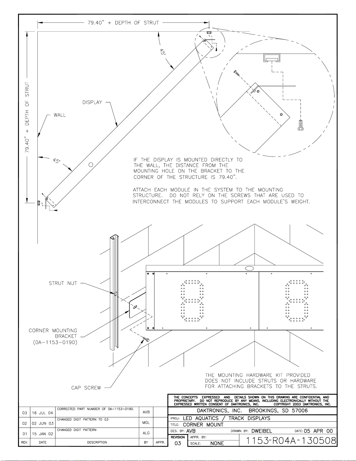
Corner-Mounting Modules, Indoors Only
Reference Drawing:
Corner Mount ................................................... Drawing A-130508
If the display is to be mounted across the corner of adjoining walls, you may order
special corner-mounting brackets as an option. Drawing A-130508 shows the
procedure for this type of mounting.
Mechanical Installation 7
Page 14

Multi-line display models that use a single vertical arrangement of modules may be
mounted with corner brackets. Horizontal display configurations, however, cannot be
mounted across a corner using the simple brackets. Such displays must be attached to
a structure or framework that spans across the corner and safely supports the entire
display. This type of mounting must be designed by a qualified engineer.
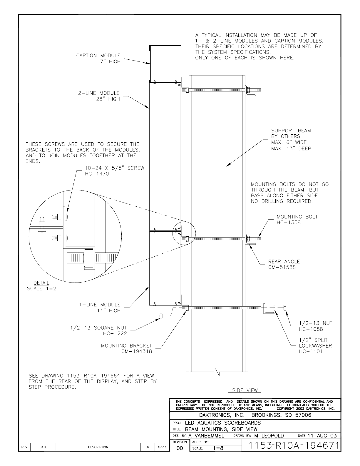
Beam Mounting Digit Modules, Outdoors
Reference Drawings:
Beam Mounting Procedure ............................. Drawing A-194664
Beam Mounting, Side View ............................. Drawing A-194671
Beam Mounting, Top View .............................. Drawing A-194674
Beam Mounting, Rear, Horizontal Display ...... Drawing A-194678
Beam Mounting, Rear, Vertical Display........... Drawing A-194677
SW-2000 Series scoreboards are frequently displayed as freestanding units, mounted
on steel beams. Because every display is different in terms of module configuration,
scoreboard options and environments, every installation will be unique.
Such beam-mounted installations require that a qualified engineer provide
specifications for both the reinforced concrete footings and the steel support beams.
Two beams are required for each column of display modules, and they must be set 4'6” apart, center-to-center. Installations of vertical and horizontal displays are shown
in Drawings A-194678 and A-194677, both of which specify the overall space
requirements for the scoreboards as well as their specific dimensions.
Each digit module has knockouts in both the rear and the end for power and signal
entrance. Power and signal are brought into one module through these external
knockouts, and connections to other modules are made internally.
Once the support beams have been installed, the scoreboard-mounting procedure is
typically a six-step process (Refer to Drawing A-194664):
1. Begin by attaching mounting brackets to the top and bottom of the lowest
digit module in the display. The brackets are fastened to the modules by
inserting 10-24 x 5/8" screws through the holes in each bracket and threading
them into the captivated nuts on the back of the module.
2. With the brackets attached, position the module against the beam and secure
it with the 15" long threaded rods with the washers and nuts provided. These
1
/2-13 x 15 threaded rods, or mounting bolts, do not go through the beam but
pass along either side; no drilling is required (Refer to Drawings A-194671
and A-194674). The square nuts go inside the bracket, and the hex nuts are
used inside the rear mounting angles that straddle the back of each support
beam. Tighten the assembly with a 3/4" socket, taking care not to over
tighten.
Note: Over tightening can deform the brackets and angles.
8 Mechanical Installation
Page 15

3. Attach the upper mounting bracket to the next module and set it on top of
the first module.
4. Insert screws through the upper bracket of the first module to secure the
bottom of the second module. This secures the bracket to the back of both
modules. (The modules will also be joined later at each end.)
5. Secure the upper bracket of the second module to the beams with bolts,
washers and nuts.
6. Join the modules together at the ends by inserting screws up through the
holes in the top of the lower module and into the captivated nuts in the
bottom of the upper module.
The building process continues in the same manner for any remaining modules.
Caption modules are attached directly to their adjoining digit modules and do not use
beam mounting brackets (Refer to Drawing A-194671).
Mechanical Installation 9
Page 16

Page 17

Section 3: Electrical Installation
Electrical installation involves the following procedures:
Providing power to the display and control locations.
Routing signal cable from the control location to the display location.
Connecting power and signal wiring between digit modules.
Installing the address and protocol plugs into each digit module.
Connecting the signal input to the first digit module.
Connecting power to the first digit module.
It may be helpful to open the front panels on the digit modules before mounting them and
installing the address and protocol plugs. This will determine the order in which the digit
module will be installed.
These steps are described in greater detail in the following sections.
3.1 Grounding Indoor Displays
Connect the scoreboard to earth ground. Proper grounding assures reliable equipment
operation and protects the equipment against damaging electrical disturbances and
lightning.
Note: It is the customer’s responsibility to properly ground the 120 V AC outlet.
Failure to ground the 120 V AC outlet connection voids the warranty for the timing
display.
3.2 Connecting Power and Signal, Indoor Displays
Reference Drawings:
Electrical Hookup, Indoor Display, 120 V ............... Drawing A-130661
Electrical Hookup, Indoor Display, 230 V ............... Drawing A-130676
The SW-2000 Series of aquatics/track scoreboards have been designed for easy
access to components, and the power and control signal hookup has been simplified.
Refer to Drawings A-130661 and A-130676 to determine where the power and
signal cable will be brought into the display. Daktronics recommends that
connections begin with the lowest module in the system, on the left side of the
cabinet. If the scoreboard is two or more modules wide, start connections with the
lowest module on the farthest left-hand side.
Front panels can be removed to allow access to the digits, cabling and other
electronic components.
Electrical Installation 11
Page 18

Electrical hookup for both 120 V and 230 V indoor scoreboards consist of a simple,
seven-step process. Begin by opening the left access panel of the module (Refer to
Drawing A-130661):
1. Mount the power/signal plate in the left side of the lowest digit module in
the display. Remove both the 2" knockout and the upper 7/8" knockout from
the left end of the module. Run the power cord out of the module through
the knockout and position the plate inside, on the end. Secure the plate with
two screws, inserting them externally through the pre-drilled holes.
2. Route the cable from the power/signal plate into the driver enclosure and
connect the 12-pin plug to the mating plug.
Note: All the connectors are “keyed”— they can only fit into the jacks one
way.
3. Insert 2'' bushings into the holes between modules.
4. Pull the power/signal cable from the lower module through the 2" hole in
the top of the cabinet up into the next module and connect the 12-pin plug to
the mating connector in the driver enclosure.
5. Repeat the connection process in Step 4 with any other modules in the
system.
6. Connect the power cord to a 120 V AC power outlet, and connect signal to
the 1/4" phone jack in the end of the bottom module.
7. Replace cover and panels. Insert a 2" hole plug in the bottom hole of the
lowest module.
The hookup procedure for a 230 V display is identical; the only difference
between the two electrical systems is the 230 V power cord (Refer to Drawing
A-130676).
3.3 Internal Cable Routing
Reference Drawing:
Internal Cable Routing ........................................... Drawing A-130679
Section 3.1 describes signal and power connections for scoreboard digit modules
arranged vertically. Horizontal, or side-by-side, modules additionally require
installation of a power/signal interconnect cable. Only one interconnect cable is
needed for each installation (Refer to Drawing A-130679).
Connect the modules by running the interconnect cable from the driver of the bottom
left module to the driver of the bottom right module. There are knockouts in the ends
of the modules through which the cable may be run. The cable is connected with
mating 12-pin plugs in each module.
12 Electrical Installation
Page 19

3.4 Grounding Outdoor Displays
Displays MUST be grounded according to the provisions outlined in Article 250 of
the National Electrical Code and according to the specifications in this manual
Daktronics recommends a resistance-to-ground of 10 ohms or less.
The electrical contractor who is performing the electrical installation can verify ground
resistance. Daktronics Sales and Service personnel can also perform this service.
The display system must be connected to an earth electrode installed at the display.
Proper grounding is necessary for reliable equipment operation. It also protects the
equipment from damaging electrical disturbances and lightning. The display must be
properly grounded or the warranty will be void.
The material for an earth-ground electrode differs from region to region and may
vary according to conditions present at the site. Consult the National Electrical Code
and any local electrical codes that may apply. The support structure of the display
cannot be used as an earth-ground electrode. The support is generally embedded in
concrete, and if it is in earth, the steel is usually primed or it corrodes, making it a
poor ground in either case.
3.5 Installing Load Centers, Outdoor Displays
Reference Drawing:
Electrical Hookup, Outdoor Display ....................... Drawing A-129998
Outdoor displays have a fully enclosed load center that brings power and signal to the
scoreboard. The harsher environment and outdoor electrical hookup requirements
mandate the use of this component. The load center is mounted in the cabinet during
display installation. The procedure is as follows:
1. Remove the lower left panels from the lowest digit module in the display,
and remove the nuts from the three screws already installed in the cabinet. If
the load center cover is on, remove it. Position the load center on the back
panel screws, and complete the mounting by tightening the nuts.
2. Route the cable from the load center into the driver enclosure and connect
the 12-pin plug to the mating plug.
3. Insert 2" bushings into the holes between modules.
4. Pull the power/signal cable from the lower module up into the module above
it and connect the cable to the 12-pin plug on its driver.
5. Follow the same procedure for the other modules.
6. Make main power and signal connections in the load center (See the detail
of the unit's interior in the lower right corner of Drawing A-129998).
7. Replace covers and panels.
Electrical Installation 13
Page 20
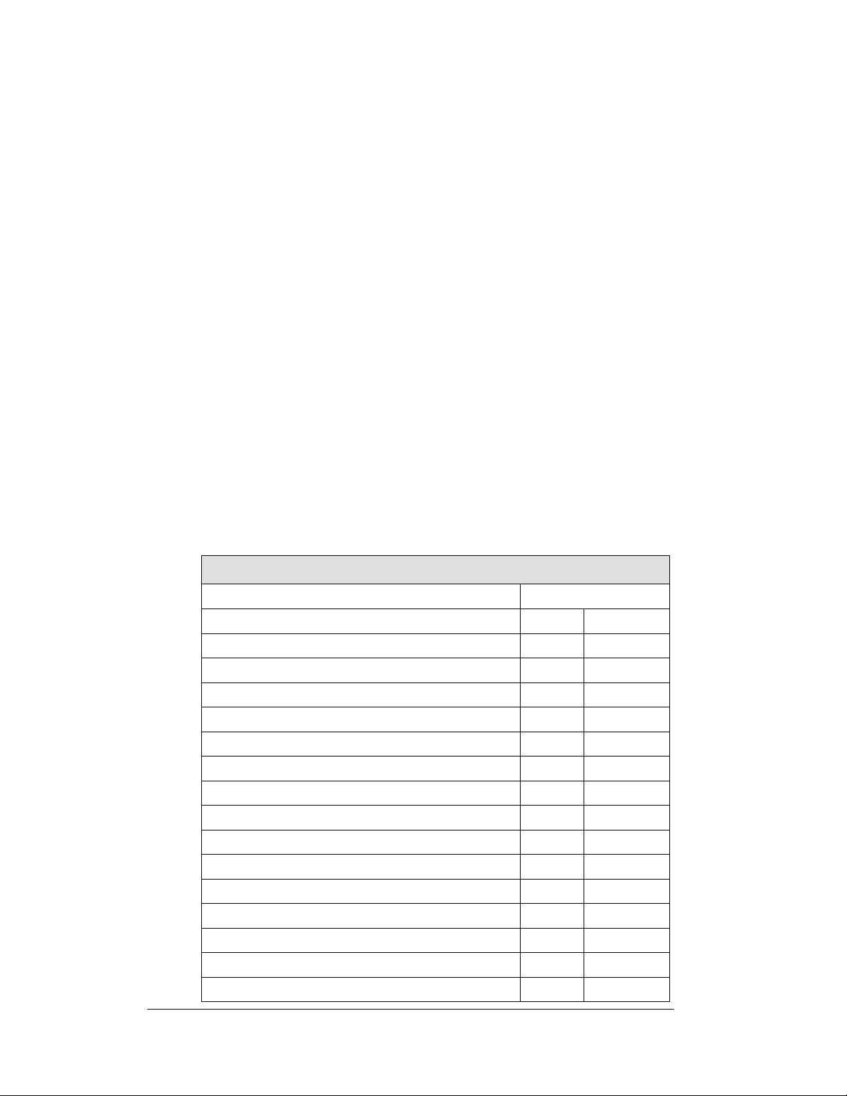
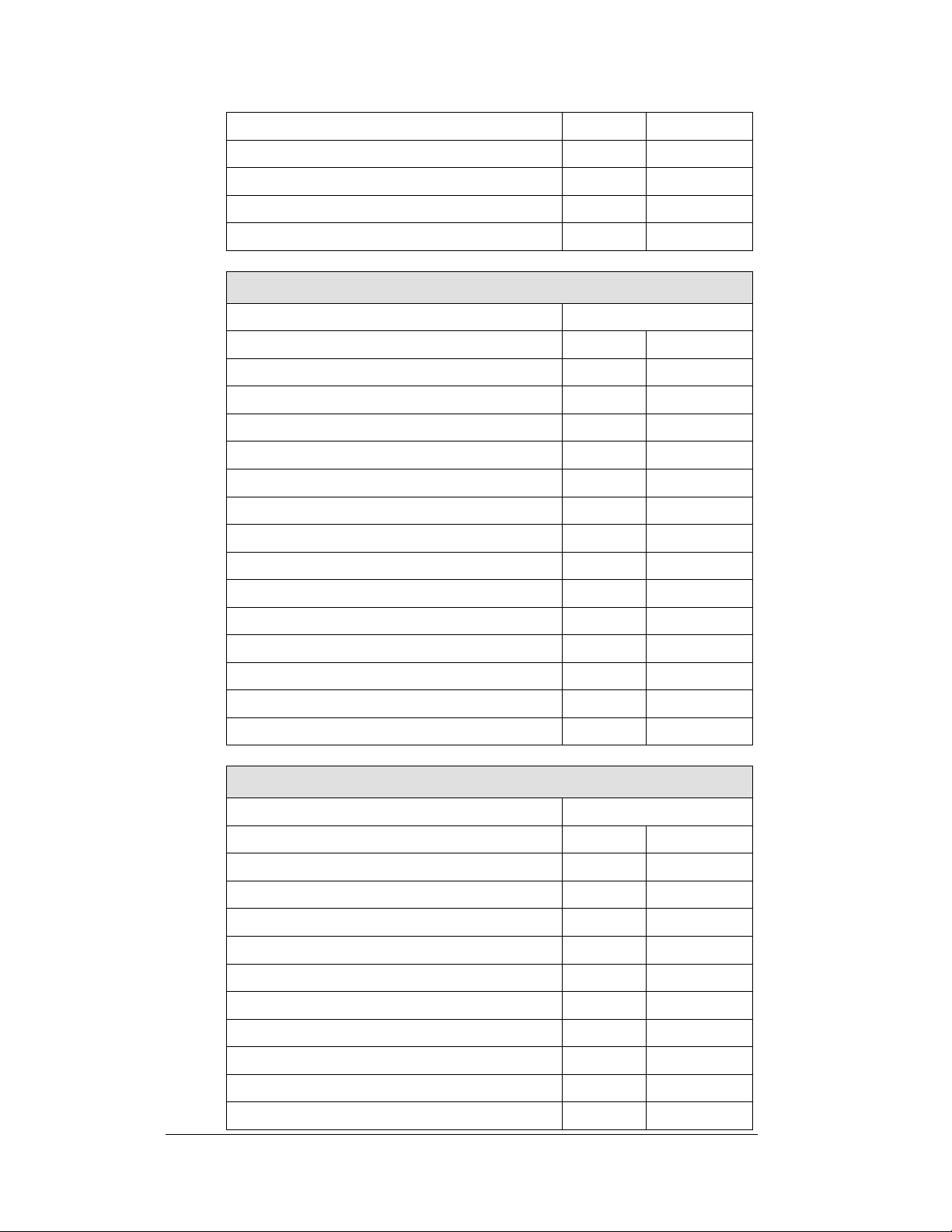
3.6 Setting Driver Addresses and Protocols
Daktronics Omni Sport 1000
Protocol=1
Address
Function
Dec.
Binary
Line 1 or 1 and 2
1
00000001
Line 2 or 2 and 3
2
00000010
Line 3 or 3 and 4
3
00000011
Line 4 or 4 and 5
4
00000100
Line 5 or 5 and 6
5
00000101
Line 6 or 6 and 7
6
00000110
Line 7 or 7 and 8
7
00000111
Line 8 or 8and 9
8
00001000
Line 9 or 9 and 10
9
00001001
Line 10
10
00001010
Event/Heat or Home/Guest, Record Time
11
00001011
N.A
12
00001100
Running Time
13
00001101
N.A
14
00001110
Line 4 MS w/ horn
15
00001111
Reference Drawings:
16 Column LED Driver II Specifications ................ Drawing A-126174
Address Configurations, Timing Displays .............. Drawing B-130318
For the scoreboard to receive signal and function properly, the driver must be set to
the correct address and protocol. This address is set with jumper wires in a 12-pin
plug which mates with jack J19 on the driver. Address and protocol plugs are
supplied in a separate kit for field installation. Plugs are marked with address or
protocol numbers. Select the appropriate plugs and connect them to the jacks on the
driver.
The LED scoreboard can be interfaced to a variety of timers. Identify your timer and
refer to the appropriate address configurations for various timing displays. This
information is also presented in the tables at the end of Section 3. (Note that Protocol
1 is used with all Daktronics Omega and Finish Lynx timing systems, Protocol 2 is
used with Colorado Time System units; one-line displays controlled by Daktronics
OmniSport 1000 or 6000 timers require no protocol or address plug; all displays
controlled by the Daktronics OmniSport 2000 require no protocol. OmniSport 2000
requires an address plug for single line displays.
Address settings, LED Fixed-Digit Aquatics/Track Displays
Multi-line Display Addresses
14 Electrical Installation
Page 21
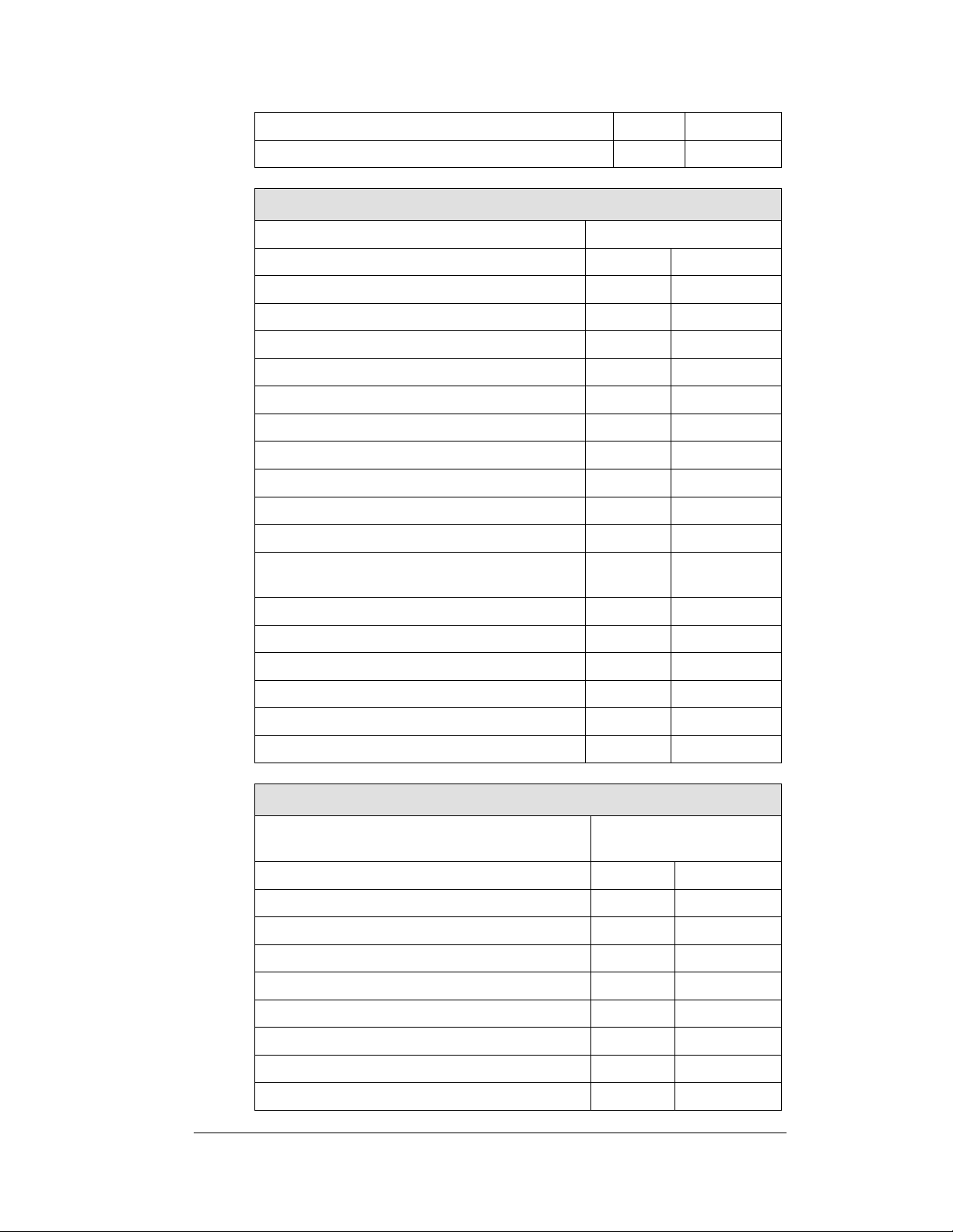
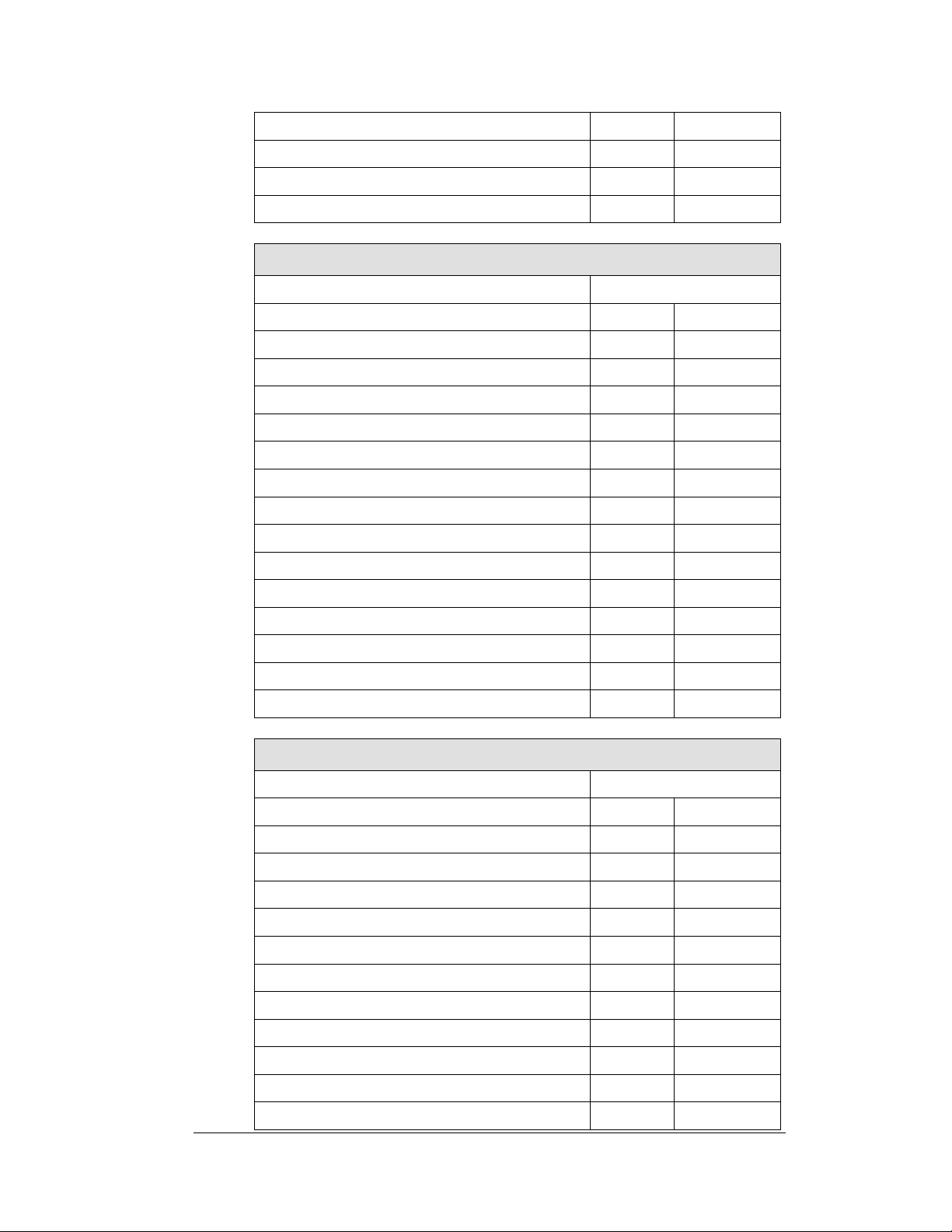
Line 6 MS w/ horn
16
00010000
Line 8 MS w/ horn
17
00010001
Daktronics Omni Sport 6000
Protocol=1
Address
Function
Dec.
Binary
Line 1 or 1 and 2
1
00000001
Line 2 or 2 and 3
2
00000010
Line 3 or 3 and 4
3
00000011
Line 4 or 4 and 5
4
00000100
Line 5 or 5 and 6
5
00000101
Line 6 or 6 and 7
6
00000110
Line 7 or 7 and 8
7
00000111
Line 8 or 8and 9
8
00001000
Line 9 or 9 and 10
9
00001001
Line 10
10
00001010
Event/Heat or Home/Guest, Lengths, Record
Time
11
00001011
Home/Guest 1/Guest 2/Guest 3
12
00001100
Running Time
13
00001101
N.A
14
00001110
Line 4 MS w/ horn
15
00001111
Line 6 MS w/ horn
16
00010000
Line 8 MS w/ horn
17
00010001
Daktronics Omni Sport 2000
Protocol=Multidrop protocol does not require a
protocol plug
Address
Function
Dec.
Binary
Stand Alone Single Line
40
101000
Line 1 or 1 and 2
41
101001
Line 2 or 2 and 3
42
101010
Line 3 or 3 and 4
43
101011
Line 4 or 4 and 5
44
101100
Line 5 or 5 and 6
45
101101
Line 6 or 6 and 7
46
101110
Line 7 or 7 and 8
47
101111
Electrical Installation 15
Page 22
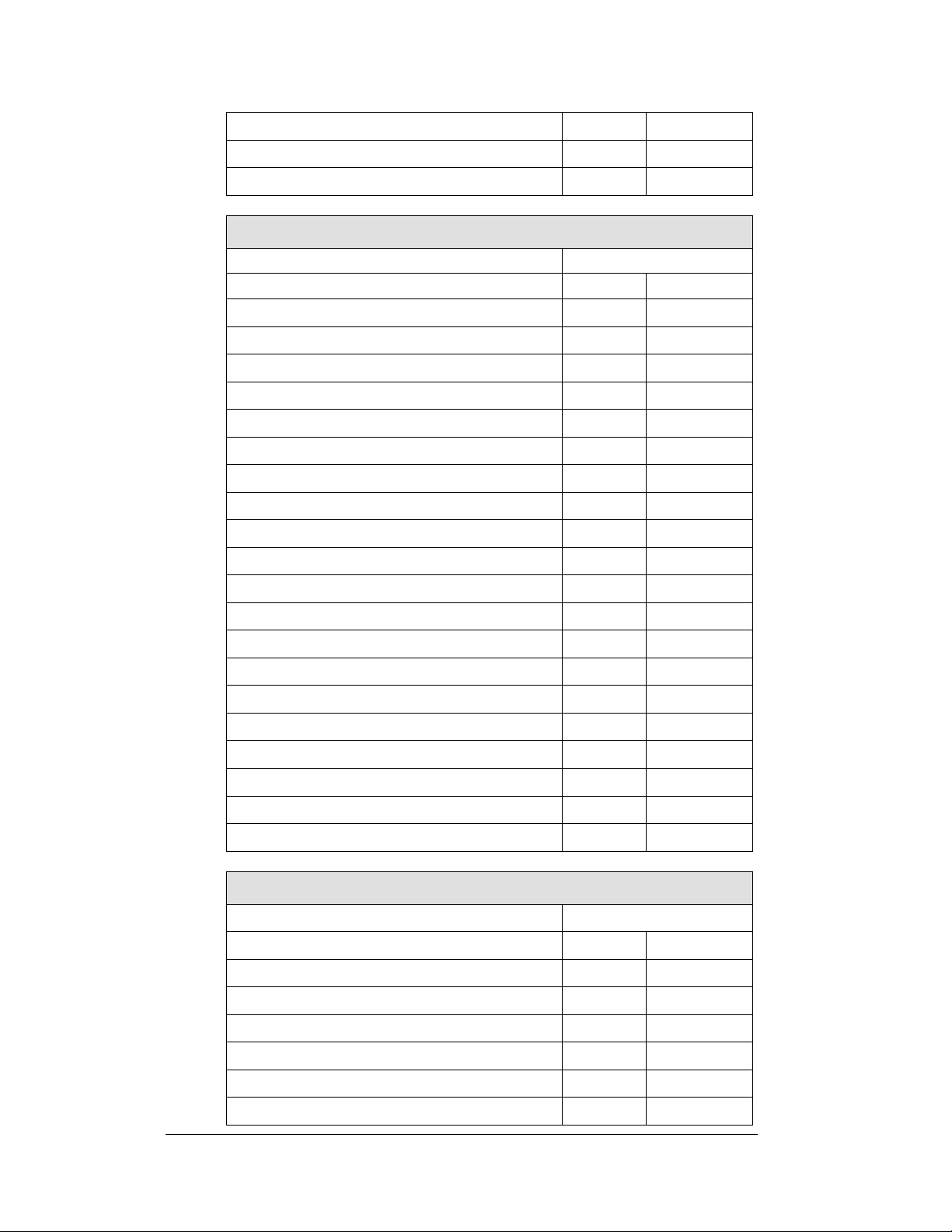
Line 8 or 8 and 9
48
110000
Line 9 or 9 and 10
49
110001
Line 10
50
110010
Home, Guest 1, Guest 2, Guest 3
31
11111
Event/Heat, Lengths, Record Time
32
100000
Omega Ares
Protocol=1
Address
Function
Dec.
Binary
1-line Timing Display
1
00000001
Line 1 or 1 and 2
1
00000001
Line 2 or 2 and 3
2
00000010
Line 3 or 3 and 4
3
00000011
Line 4 or 4 and 5
4
00000100
Line 5 or 5 and 6
5
00000101
Line 6 or 6 and 7
6
00000110
Line 7 or 7 and 8
7
00000111
Line 8 or 8and 9
8
00001000
Line 9 or 9 and 10
9
00001001
N.A.
10
00001010
Event/Heat, or Home/Guest, Rec. Time
11
00001011
Home, Guest, Guest, Guest
12
00001100
Running Time
13
00001101
Omega OSM6 or Scan’O’Vision
Protocol=1
Address
Function
Dec.
Binary
1-line Timing Display
1
00000001
Line 1 or 1 and 2
1
00000001
Line 2 or 2 and 3
2
00000010
Line 3 or 3 and 4
3
00000011
Line 4 or 4 and 5
4
00000100
Line 5 or 5 and 6
5
00000101
Line 6 or 6 and 7
6
00000110
Line 7 or 7 and 8
7
00000111
Line 8 or 8and 9
8
00001000
Line 9 or 9 and 10
9
00001001
16 Electrical Installation
Page 23
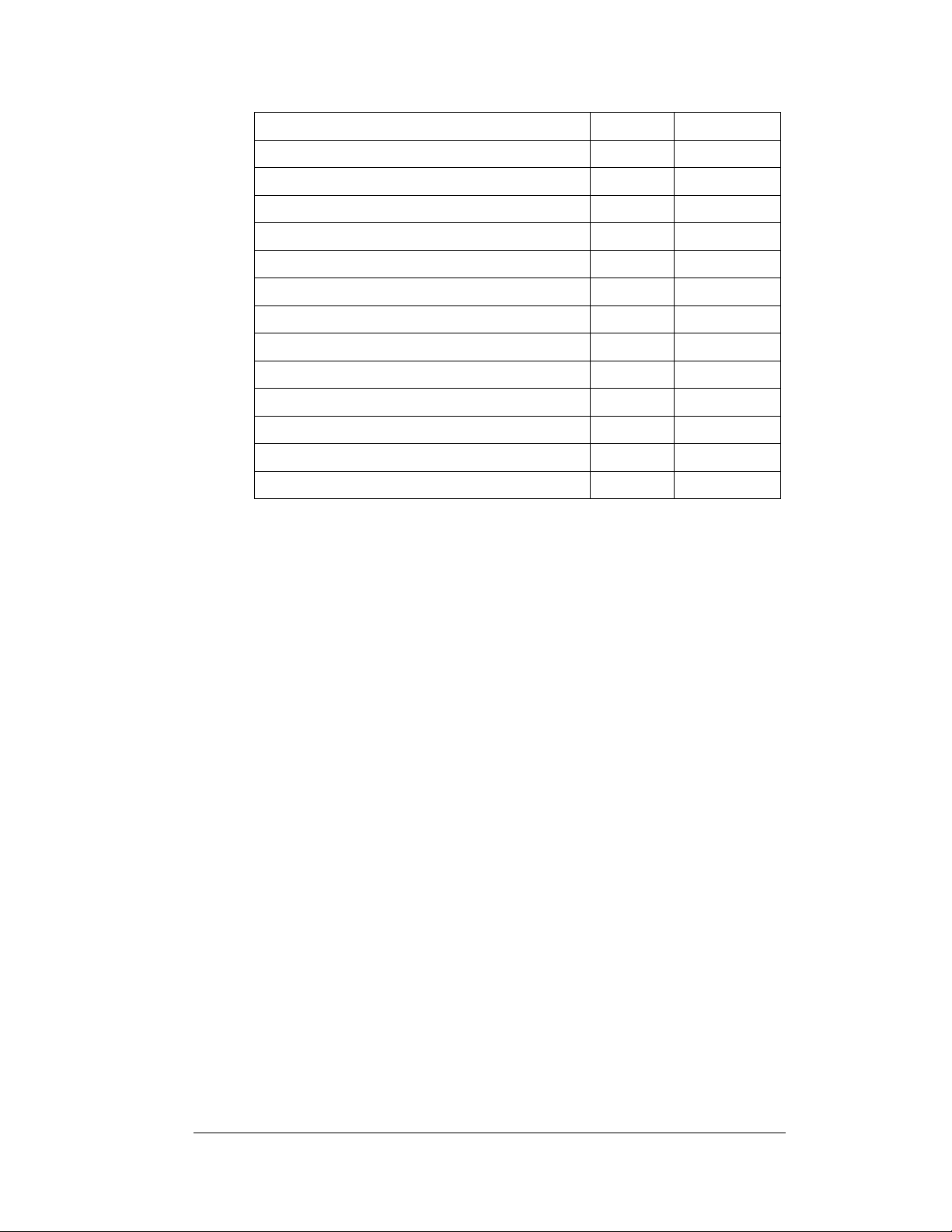
N.A.
10
00001010
N.A.
11
00001011
N.A.
12
00001100
N.A.
13
00001101
Omega Power Time
Protocol=1
Address
Function
Dec.
Binary
1-line Timing Display
1
00000001
Line 1 or 1 and 2
1
00000001
Line 2 or 2 and 3
2
00000010
Line 3 or 3 and 4
3
00000011
Line 4 or 4 and 5
4
00000100
Line 5 or 5 and 6
5
00000101
Line 6 or 6 and 7
6
00000110
Line 7 or 7 and 8
7
00000111
Line 8
8
00001000
N.A.
9
00001001
N.A.
10
00001010
Event/Heat
11
00001011
N.A.
12
00001100
Running Time
13
00001101
FinishLynx
Protocol=1
Address
Function
Dec.
Binary
1-line Timing Display
1
00000001
Line 1 or 1 and 2
1
00000001
Line 2 or 2 and 3
2
00000010
Line 3 or 3 and 4
3
00000011
Line 4 or 4 and 5
4
00000100
Line 5 or 5 and 6
5
00000101
Line 6 or 6 and 7
6
00000110
Line 7 or 7 and 8
7
00000111
Line 8 or 8 and 9
8
00001000
Line 9 or 9 and 10
9
00001001
N.A.
10
00001010
Electrical Installation 17
Page 24
Event/Heat
11
00001011
N.A.
12
00001100
Running Time
13
00001101
Colorado Timing, 9600 BAUD
Protocol=2
Address
Function
Dec.
Binary
Line 1 or 1 and 2
1
00000001
Line 2 or 2 and 3
2
00000010
Line 3 or 3 and 4
3
00000011
Line 4 or 4 and 5
4
00000100
Line 5 or 5 and 6
5
00000101
Line 6 or 6 and 7
6
00000110
Line 7 or 7 and 8
7
00000111
Line 8 or 8and 9
8
00001000
Line 9 or 9 and 10
9
00001001
Line 10
10
00001010
Lengths, Record Time
11
00001011
Event/Heat
11
00001011
Home, Guest
13
00001101
N.A
14
00001110
1-line timing
15
00001111
N.A.
16
00010000
N.A.
17
00010001
N.A.
18
00010010
N.A.
19
00010011
Home, Guest, Guest, Guest
20
00010100
Colorado Timing, 2400 BAUD
Protocol=2
Address
Function
Dec.
Binary
Line 1 or 1 and 2
33
01000001
Line 2 or 2 and 3
34
01000010
Line 3 or 3 and 4
34
01000011
Line 4 or 4 and 5
35
01000100
Line 5 or 5 and 6
36
01000101
Line 6 or 6 and 7
37
01000110
18 Electrical Installation
Page 25
Line 7 or 7 and 8
38
01000111
Line 8 or 8and 9
39
01001000
Line 9 or 9 and 10
40
01001001
Line 10
41
01001010
Lengths, Record Time
42
01001011
Event/Heat
42
01001011
Home, Guest
44
01001101
N.A
45
01001110
1-line timing
46
01001111
N.A.
47
01010000
N.A.
48
01010001
N.A.
49
01010010
N.A.
50
01010011
Home, Guest, Guest, Guest
51
01010100
One-Line Timing Display Controlled by Daktronics OmniSport 1000, or 6000 Timers
Protocol= 0 (No protocol plug required)
Address= 0 (No protocol plug required)
Auxiliary Scoring Display Modules Controlled By Daktronics All Sport 4000 Series Controller
Protocol= 1
Event/Heat, Lengths, Record Time Address= 11
Home/Guest 1/Guest 2/Guest 3 Address= 12
Electrical Installation 19
Page 26

Page 27
Connector No.
Function
1 through 16
Output to digits and indicators
17
Control signal and power input
18
Control for horn
19
Address
Section 4: Maintenance and
Troubleshooting
IMPORTANT NOTES:
1. Disconnect power before doing any repair or maintenance
work on the display!
2. Allow only qualified service personnel access to internal
display electronics.
3. Disconnect power when the display is not in use.
4.1 Cabinet Specifications
Reference Drawings:
Mechanical Specifications, 2-Line Digit Module ..... Drawing A-194679
Mechanical Specifications, 1-Line Digit Module ..... Drawing A-194673
Mechanical Specifications, Ad Panels ................... Drawing A-194676
Cabinets for the modules in the SW-2000 Series are of all-aluminum construction.
The drawings referenced above, A-194673, A-194679, and A-194676, give exact
dimensions, screw and knockout locations, and other mechanical specifications. The
illustrations include details for the one-line digit module, the two-line digit module,
and for ad panels that may be attached to the display as well.
4.2 LED Driver
Reference Drawing:
16 Column LED Driver II Specifications ................. Drawing A-126174
The task of switching LEDs on and off is performed by the LED driver (Refer to
Drawing A-126174). Each driver has 19 connectors providing power and signal
inputs/outputs to digits and indicators. The function of each of these connectors is as
follows.
Maintenance and Troubleshooting 21
Page 28

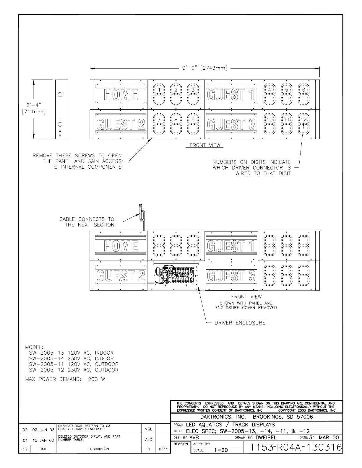
Output connectors 1 through 16 each have nine pins. Pin 7 provides power to the
digit or indicators wired to that connector. The other eight pins provide switching
connections. The electrical specification drawings for each of the models in the SW2000 Series, shown at the beginning of this section, specify the driver connectors
controlling the digits. Numbers on each digit indicate which connector is wired to
that digit. Scoreboard model numbers are shown on the lower left side of each
drawing.
4.3 Segmentation
Reference Drawing:
Digit Service ........................................................... Drawing A-130891
In each digit, certain LEDs always go on and off together. These groupings of LEDs
are referred to as segments. Drawing A-130891 shows which connector pin number
is wired to each digit segment and the wiring color code used throughout the display
(illustrated at the lower left corner of the drawing).
4.4 Component Location and Access
Reference Drawings:
Electrical Hookup, Indoor Display, 120 V .............. Drawing A-130661
Electrical Hookup, Indoor Display, 230 V .............. Drawing A-130676
Digit Service ........................................................... Drawing A-130891
Drawings A-130661, A-130676, and A-130891 show front views of display
modules. The digit circuit board, the platform for the LEDs, is mounted on the front
panel in each section. The panels are easily removed for front access.
The drivers are located on the left side of each module (typically behind the second
panel), and the load center, if present, is immediately to the left of the driver. The
power/signal plate used in indoor scoreboards is usually mounted on the left end of
the module cabinet.
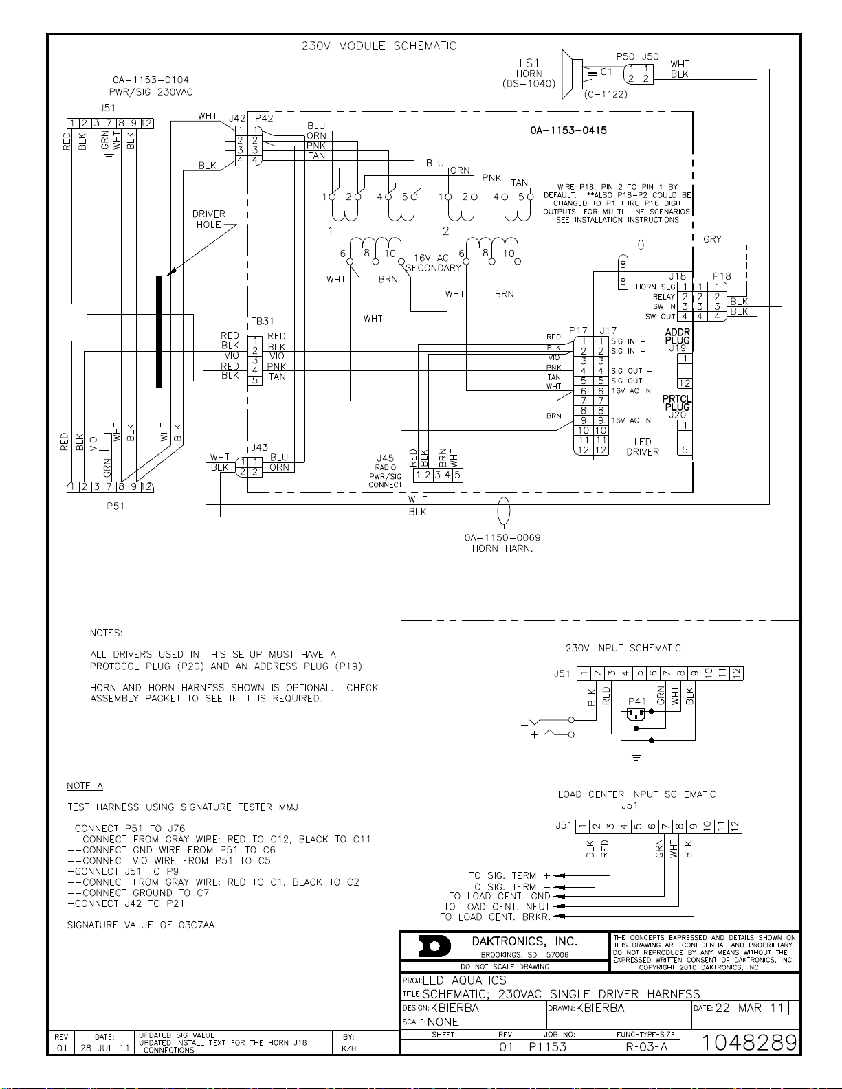
4.5 Schematic
Reference Drawing:
Schematic; 120VAC Single Driver, Harness ....... Drawing A-1048280
Schematic; 230VAC Single Driver, Harness ....... Drawing A-1048289
Drawing A-1048280 is the schematic diagram of the power and signal inputs and all
wiring in 120VAC SW-2000 Series displays. Drawing A-1048289 is the schematic
diagram of the power and signal inputs and all wiring in 230VAC SW-2000 Series
displays.
Disconnect power before servicing the display.
Disconnect power when the display is not in use. Prolonged power-on may shorten
the life of some electronic components.
22 Maintenance and Troubleshooting
Page 29

Symptom/Condition
Possible Cause
Scoreboard will not light
Console not connected or poor connection
No power to control console
No power to the scoreboard
Driver fuse blown
Main fuse blown
Garbled display
Internal driver logic malfunction
Control console malfunction
Digit will not light
Black wire to digit broken
Poor contact at driver connection
Driver malfunction
Segment will not light
Broken LED or connection
Driver shift register failure
Broken wire between lamp driver and digit
Poor contact at driver connector
Segment stays lit
Driver shift register failure
Short circuit on digit
Date appears in the wrong
place on the display
Incorrect address settings on drivers
(consult tables and set correct addresses)
Description
Part Number
Load center
0A-1153-0177
Power/signal plate, 120 V
0A-1153-0105
Power/signal plate, 230 V
0A-1153-0106
Address Protocol Plug Set
0A-1153-0187
Horn; 120 V AC 60Hz LS1
0A-1152-0332
4.6 Troubleshooting
This section lists some symptoms and problems that may be encountered with
scoreboard operation. For these symptoms, possible cause and corrective actions are
indicated. This list does not include every possible problem, but it does represent
some of the more common situations that may occur.
4.7 Replacement Parts List
To prevent loss due to theft, Daktronics recommends purchasing a lockable cabinet
to store manuals and replacement or spare parts. Refer to the appropriate
supplementary manual for a complete list of replacement parts.
Maintenance and Troubleshooting 23
Page 30

Cable, 22 AWG, one pair
W-1077
Junction box; phone jack
0A-1009-0038
LED driver
0P-1150-0127
Digit, 10” Red, Outdoor
0P-1192-0265 (prior to January 2013)
0A-1192-5121 (after January 2013)
Digit, 10” Amber, Outdoor
0P-1192-0266 (prior to January 2013)
0A-1192-5221 (after January 2013)
Digit 10”, Red, Indoor
0P-1150-0240 (prior to January 2013)
0A-1192-5122 (after January 2013)
Digit 10”, Amber, Indoor
0P-1150-0241 (prior to January 2013)
0A-1192-5222 (after January 2013)
Transformer, 16 V
T-1066
Signal cable, 10'
W-1340
Signal cable, 20'
W-1236
Signal cable, 30'
W-1238
Signal cable, 50'
W-1237
Signal cable, 100'
W-1381
24 Maintenance and Troubleshooting
Page 31

Appendix A: Reference Drawings
A Drawing Title Drawing Number
Track Scbd. w/ Finish Lynx, in Press Box....................................................... A-104300
Address Table, 1 through 128 ........................................................................ A-115078
Scan’O’Vision LED Driver Address Configuration on 12 Pin. ......................... A-118398
Equipment Layout, 50 M Swim, Course #1, indeck ........................................ B-121329
16 Column LED Driver II Specifications.......................................................... A-126174
Module Model Descriptions, LED Aquatics/Track .......................................... A-129639
Elec Spec: SW-2101-11, -12, -13 & -14 ......................................................... A-129652
Strut Spacing, Horizontal Wall Mount. ............................................................ A-129905
End Bracket Attach, Horizontal Wall ............................................................... A-129906
Horizontal Wall Mount, Final Steps. ................................................................ A-129907
Elec Spec: SW-2001-11, -12, -13 & -14 ......................................................... A-129984
Electrical Hookup, Display .............................................................................. A-129998
Elec Spec: SW-2003-11, -12, -13 & -14 ......................................................... A-130053
Elec Spec: SW-2004-11, -12, -13 & -14 ......................................................... A-130054
Model Configurations, Swim/Track Timing ..................................................... A-130101
Model Configurations, Aquatics Multi-sport .................................................... A-130102
Elec Spec: SW-2006-11, -12, -13 & -14 ......................................................... A-130284
Elec Spec: SW-2007-11, -12, -13 & -14 ......................................................... A-130286
Elec Spec: SW-2008-11, -12, -13 & -14 ......................................................... A-130309
Elec Spec: SW-2002-11, -12, -13 & -14 ......................................................... A-130312
Elec Spec: SW-2005-11, -12, -13 & -14 ......................................................... A-130316
Address Configurations, Timing Displays ....................................................... B-130318
Caption Layout, 6-Lane Multisport Systems. .................................................. A-130319
Caption Layout, 8-Lane Multisport Systems. .................................................. A-130321
Corner Mount .................................................................................................. A-130508
Vertical Wall Mounting .................................................................................... A-130545
Electrical Hookup, Indoor Display, 120 V ....................................................... A-130661
Electrical Hookup, Indoor Display, 230 V ....................................................... A-130676
Internal Cable Routing .................................................................................... A-130679
Caption Layout, 10-Lane Multisport Systems. ................................................ A-130801
Caption Module Detail..................................................................................... A-130840
Digit Service .................................................................................................... A-130891
Riser Diagram with OmniSport 6000 .............................................................. A-130977
Riser Diagram with OmniSport 1000 .............................................................. A-130978
Riser Diagram with CTS Timer ....................................................................... B-130979
Riser Diagram with Omega Timer .................................................................. A-131037
Elec Spec: SW-2009-11, -12, -13 & -14 ......................................................... A-131039
Riser Diagram with All Sport 4000 .................................................................. A-131226
System Riser; Track Scbd w/ Omni 2000, in field .......................................... A-186548
Beam Mounting Procedure. ............................................................................ A-194664
Beam Mounting, Side View ............................................................................. A-194671
Mechanical Specifications, 1-Line Digit Module ............................................. A-194673
Beam Mounting, Top View .............................................................................. A-194674
Mechanical Specifications, Ad Panels ............................................................ A-194676
Beam Mounting Rear, Vertical Display ........................................................... A-194677
Beam Mounting, Rear, Horizontal Display ...................................................... A-194678
Reference Drawings 25
Page 32

Mechanical Specifications, 2-Line Digit Module .............................................. A-194679
Electrical Hookup, Radio Hookup ................................................................... A-305509
Schematic; 120VAC Single Driver, Harness ................................................. A-1048280
Schematic; 230VAC Single Driver, Harness ................................................. A-1048289
26 Reference Drawings
Page 33

Page 34

Page 35

Page 36

%+
83'$7('3$57180%(563(55('/,1(6
'$7(5(9 %<
)(% --/
'$.7521,&6,1&
(48,30(17/$<28706:,0&2856(,1'(&.
-:$51(
121(
6+((7 -2%125(9
83'$7('%2$5'(5$1'7,7/(%/2&.
'5$:1 '$7(
+%21(5 6(3
3 5
7+(&21&(376(;35(66('$1''(7$,/66+2:1217+,6
'5$:,1*$5(&21),'(17,$/$1'35235,(7$5<'2127
5(352'8&(%<$1<0($16:,7+2877+((;35(66('
:5,77(1&216(172)'$.7521,&6,1&
&23<5,*+7'$.7521,&6,1&
%
Page 37

Page 38

Page 39

Page 40

Page 41

Page 42

Page 43

Page 44

Page 45

Page 46

Page 47

Page 48

Page 49

Page 50

Page 51

Page 52

Page 53
Page 54

Page 55

Page 56

Page 57
Page 58

Page 59

Page 60

Page 61

Page 62

Page 63

Page 64

Page 65

Page 66

Page 67

%+
&767,0(5:,5(':,7+'$.7521,&66,*1$/&$%/(&767,0(5:,5('86,1*&2/25$'26,*1$/&$%/(
$
$
(;,67,1*
&2/25$'2-%2;
(;,67,1*&2/25$'2
0212-$&.
-%2;
:'$.7521,&6
67(527267(52&$%/(
'$.7521,&6
,1'225',63/$<
9$&259$&9$&259$&
'$.7521,&6
,1'225',63/$<
$
:'$.7521,&6
67(527267(52&$%/(
$
'$.7521,&6
287'225',63/$<
6,*1$/685*(&$5'
6,*1$/,1
'$.7521,&6
287'225',63/$<
6,*1$/685*(&$5'
6,*1$/,1
25
$
(;,67,1*
&2/25$'2-%2;
(;,67,1*&2/25$'2
0212720212&$%/(
5(3/$&((;,67,1*&2/25$'2
0212-$&.:,7+'$.7521,&6
-%2;
$67(5(2-%2;
:,5('723/8*,172'$.7521,&6
-%2;)25),;('',*,76&%'
$
$'$.7521,&6
67(527267(5(2
&$%/(
',63/$<66:,00,1*,1)221/<
121
&767,0(5:,//12723(5$7(''',*,76
2108/7,63257/,1(,1',9,1*02'(
$''5(66('&255(&7/<,7:,//6281'
7+(+251)25:$7(532/25()(572
7+(',63/$<0$18$/)25$''5(66,1*
:,5('723/8*,172&767,0(5
83'$7('6,*1$/&211(&7,21)5207,0(5726&%'
'$7(5(9 %<
129 &0(
/('$48$7,&66&25(%2$5'
5,6(5',$*5$0:,7+&767,0(5
121(
$''('7:2',))(5(170(7+2'62)&211(&7,21
'$.7521,&6,1&
$9%
6+((7 -2%125(9
7+(&21&(376(;35(66('$1''(7$,/66+2:1217+,6
'5$:,1*$5(&21),'(17,$/$1'35235,(7$5<'2127
5(352'8&(%<$1<0($16:,7+2877+((;35(66('
:5,77(1&216(172)'$.7521,&6,1&
&23<5,*+7'$.7521,&6,1&
'5$:1 '$7(
':(,%(/ $35
3 5
$
Page 68

Page 69

Page 70

Page 71

STANDS
W-1238 (30')
0A-1056-0156 BUTTON W/
12' TYPICAL @ 8
0A-1240-0010 BUTTON INTERFACE
W/ 20' CORD
OMNISPORT
J13 POWER
J15 FAR
J14 NEAR
J12 START
J11 FAR
J10 NEAR
J9-S-SWITCH
J8-M-SWITCH
J7-S-INPUT
J6-RESULTS
J4-E-PORT
J3-SCBD
J2-SCBD
2000E
LL-2573 TRACK
J5-RTD
0A-1091-0227,
SCBD J-BOX
TRACK SYSTEM RISER DIAGRAM
TRACK SCBD WITH
OMNISPORT 2000E, TRACK SIDE
A
A
TRACK EQUIPMENT BOM:
0A-1240-0082 OMNISPORT 2000E (TRACK TIMER) @ 1
W-1238 30' SIGNAL CABLE @ 1
0A-1091-0227 TRACK SIDE J-BOX @ 1
0A-1240-0010 BUTTON INTERFACE @ 1
0A-1056-0156 12' PUSH BUTTON @ 9
-IF MORE THAN 8 LANES ARE REQUIRED, OR MORE
THAN 1 BUTTON PER LANE, REPLACE 0A-1240-0010
WITH 0A-1240-0016 AND ORDER THE NUMBER OF
BUTTONS NEEDED.
SCOREBOARD SIGNAL CABLE OPTIONS:
- W-1234, 2 PAIR SIGNAL CABLE.
CONDUIT REQUIRED.
LAPTOP COMPUTER
BY
COMPUTER
HYTEK
PRINTER
NETWORKUSB
COMM1*
OTHERS
PRESS BOX
AH
OMNI SPORT 2000E TIMER
SYSTEM RISER: TRACK SCBD /W OMNI 2K- TRACK SIDE
MMILLER 08 APR 03
P1240 R
01 A
1=1
MMILLER
186548
06
01 13 MAY 03 SAL
ADDED TYPICAL FOR ALL CABLE
REQUIREMENTS IN NOTE
02 10 FEB 04 MWM
UPDATED TITLE BLOCK AND DRAWING TEXT.
03 28 DEC 05 SAL
DELETED START CABLE AND START
EQUIPMENT OPTIONS
04 15 SEPT 09 CME
ADDED RADIO TO HYTEK OPTION
05 18 APR 12 KZB
UPDATED CABLES FROM RADIOS
0A-1240-0065
CONNEXLINK PRO
900MHZ
W-1267
**RADIO TO HYTEK OPTION**
W-2060
**RADIO TO HYTEK OPTION**
*A-2221
USB/SERIAL
ADAPTER
W-1267 - 9 PIN DB MALE TO FEMALE
STRAIGHT THROUGH SERIAL CABLE
FEM
W-2060 - 9 PIN DB MALE TO MALE
NULL MODEM SERIAL CABLE
0A-1240-0065
CONNEXLINK PRO
900MHZ
FEM
06 14 FEB 14 SMB
UPDATED HYTEK RADIO EQUIPMENT.
0A-1240-0082
OMNISPORT 2000 WITH E-NET
Page 72

Page 73
Page 74

Page 75

Page 76

Page 77

Page 78

Page 79

Page 80

4424
LL-2567
POWER
RADIO IN RANGE
DATA OUT
DAKTRONICS
WIRELESS RECEIVER
HORN
2
3
4
1
Page 81

Page 82
Page 83

Appendix B: Daktronics Warranty and
Limitation of Liability
Daktronics Warranty and Limitation of Liability 27
Page 84

Page 85

DAKTRONICS WARRANTY & LIMITATION OF LIABILITY
This Warranty and Limitation of Liability (the “Warranty”) sets forth the warranty provided by Daktronics with respect to the Equipment. By accepting delivery of the
Equipment, Purchaser agrees to be bound by and accept these terms and conditions. Unless otherwise defined herein, all terms within the Warranty shall have the
same meaning and definition as provided elsewhere in the Agreement.
DAKTRONICS WILL ONLY BE OBLIGATED TO HONOR THE WARRANTY SET FORTH IN THESE TERMS AND CONDITIONS UPON RECEIPT OF FULL PAYMENT FOR THE
EQUIPMENT.
1. Warranty Coverage
2. Exclusion from Warranty Coverage
A. Daktronics warrants to the original end-user that the Equipment will be free from Defects (as defined below) in materials and
workmanship for a period of one (1) year (the “Warranty Period”). The Warranty Period shall commence on the earlier of: (i) four weeks from the date
that the Equipment leaves Daktronics’ facility; or (ii) Substantial Completion as defined herein. The Warranty Period shall expire on the first anniversary
of the commencement date.
“Substantial Completion” means the operational availability of the Equipment to the Purchaser in accordance with the Equipment’s specifications,
without regard to punch-list items, or other non-substantial items which do not affect the operation of the Equipment.
B. Daktronics’ obligation under this Warranty is limited to, at Daktronics’ option, replacing or repairing, any Equipment or part thereof that is found by
Daktronics not to conform to the Equipment’s specifications. Unless otherwise directed by Daktronics, any defective part or component shall be
returned to Daktronics for repair or replacement. This Warranty does not include on-site labor charges to remove or install these components.
Daktronics may, at its option, provide on-site warranty service. Daktronics shall have a reasonable period of time to make such replacements or repairs
and all labor associated therewith shall be performed during regular working hours. Regular working hours are Monday through Friday between 8:00
a.m. and 5:00 p.m. at the location where labor is performed, excluding any holidays observed by either Purchaser or Daktronics.
C. Daktronics shall pay ground transportation charges for the return of any defective component of the Equipment. All such items shall be shipped by
Purchaser DDP Daktronics; designated facility. If returned Equipment is repaired or replaced under the terms of this warranty, Daktronics will prepay
ground transportation charges back to Purchaser and shall ship such items DDP Purchaser’s designated facility; otherwise, Purchaser shall pay
transportation charges to return the Equipment back to the Purchaser and such Equipment shall be shipped Ex Works Daktronics designated facility. All
returns must be pre-approved by Daktronics before shipment. Daktronics shall not be obligated to pay freight for any unapproved return. Purchaser
shall pay any upgraded or expedited transportation charges.
D. Any replacement parts or Equipment will be new or serviceably used, comparable in function and performance to the original part or Equipment, and
warranted for the remainder of the Warranty Period. Purchasing additional parts or Equipment from the Seller does not extend the Warranty Period.
E. Defects shall be defined as follows. With regard to the Equipment (excepting LEDs), a “Defect” shall refer to a material variance from the design
specifications that prohibit the Equipment from operating for its intended use. With respect to LEDs, “Defects” are defined as LED pixels that cease to
emit light. The limited warranty provided by Daktronics does not impose any duty or liability upon Daktronics for partial LED pixel degradation nor does
the limited warranty provide for the replacement or installation of communication methods including but not limited to, wire, fiber optic cable, conduit,
trenching, or for the purpose of overcoming local site interference radio equipment substitutions.
EXCEPT AS OTHERWISE EXPRESSLY SET FORTH IN THIS WARRANTY, TO THE MAXIMUM EXTENT PERMITTED BY APPLICABLE LAW, DAKTRONICS DISCLAIMS
ANY AND ALL OTHER PROMISES, REPRESENTATIONS AND WARRANTIES APPLICABLE TO THE EQUIPMENT AND REPLACES ALL OTHER WARRANTIES OR
CONDITIONS, EXPRESS OR IMPLIED, INCLUDING, BUT NOT LIMITED TO ANY IMPLIED WARRANTIES OR CONDITIONS OF MERCHANTABILITY, FITNESS FOR A
PARTICULAR PURPOSE, ACCURACTY OR QUALITY OF DATA. NO ORAL OR WRITTEN INFORMATION, OR ADVICE GIVEN BY THE COMPANY, ITS AGENTS OR
EMPLOYEES, SHALL CREATE A WARRANTY OR IN ANY WAY INCREASE THE SCOPE OF THIS LIMITED WARRANTY.
THIS LIMITED WARRANTY IS NOT TRANSFERABLE.
The limited warranty provided by Daktronics does not impose any duty or liability upon Daktronics for:
A. Any damage occurring, at any time, during shipment of Equipment unless otherwise provided for in the Agreement. When returning Equipment to
Daktronics for repair or replacement, Purchaser assumes all risk of loss or damage, and agrees to use any shipping containers that might be provided by
Daktronics and to ship the Equipment in the manner prescribed by Daktronics;
B. Any damage caused by the improper installation, adjustment, repair or service of the Equipment by anyone other than personnel of Daktronics or its
authorized repair agents;
C. Damage caused by the failure to provide a continuously suitable environment, including, but not limited to: (i) neglect or misuse, (ii) a failure or
sudden surge of electrical power, (iii) improper air conditioning, humidity control, or other environmental conditions outside of the Equipment’s
technical specifications such as extreme temperatures, corrosives and metallic pollutants, or (iv) any other cause other than ordinary use;
D. Damage caused by fire, flood, earthquake, water, wind, lightning or other natural disaster, strike, inability to obtain materials or utilities, war,
terrorism, civil disturbance or any other cause beyond Daktronics’ reasonable control;
Copyright © Daktronics, Inc. SL-02374 Rev 12 27Jun14 Page 1 of 2
Page 86

DAKTRONICS WARRANTY & LIMITATION OF LIABILITY
E. Failure to adjust, repair or replace any item of Equipment if it would be impractical for Daktronics personnel to do so because of connection of the
Equipment by mechanical or electrical means to another device not supplied by Daktronics, or the existence of general environmental conditions at the
site that pose a danger to Daktronics personnel;
3. Limitation of Liability
4. Assignment of Rights
5. Governing Law
6. Availability of Extended Service Agreement
F. Any statements made about the product by any salesperson, dealer, distributor or agent, unless such statements are in a written document signed by
an officer of Daktronics. Such statements as are not included in a signed writing do not constitute warranties, shall not be relied upon by Purchaser and
are not part of the contract of sale;
G. Any damage arising from the use of Daktronics products in any application other than the commercial and industrial applications for which they are
intended, unless, upon request, such use is specifically approved in writing by Daktronics;
H. Any performance of preventive maintenance;
J. Third-party systems and other ancillary equipment including without limitation front-end video control systems, audio systems, video processors and
players, HVAC equipment, batteries and LCD screens;
K. Incorporation of accessories, attachments, software or other devices not furnished by Daktronics; or
L. Paint or refinishing the Equipment or furnishing material for this purpose.
Daktronics shall be under no obligation to furnish continued service under this Warranty if alterations are made to the Equipment without the prior
written approval of Daktronics.
It is specifically agreed that the price of the Equipment is based upon the following limitation of liability. In no event shall Daktronics (including its
subsidiaries, affiliates, officers, directors, employees, or agents) be liable for any special, consequential, incidental or exemplary damages arising out of or
in any way connected with the Equipment or otherwise, including but not limited to damages for lost profits, cost of substitute or replacement
equipment, down time, lost data, injury to property or any damages or sums paid by Purchaser to third parties, even if Daktronics has been advised of
the possibility of such damages. The foregoing limitation of liability shall apply whether any claim is based upon principles of contract, tort or statutory
duty, principles of indemnity or contribution, or otherwise.
In no event shall Daktronics be liable to Purchaser or any other party for loss, damage, or injury of any kind or nature arising out of or in connection with
this Warranty in excess of the purchase price of the Equipment actually delivered to and paid for by the Purchaser. The Purchaser’s remedy in any
dispute under this Warranty shall be ultimately limited to the Purchase Price of the Equipment to the extent the Purchase Price has been paid.
The Warranty contained herein extends only to the original end-user (which may be the Purchaser) of the Equipment and no attempt to extend the
Warranty to any subsequent user-transferee of the Equipment shall be valid or enforceable without the express written consent of Daktronics.
The rights and obligations of the parties under this warranty shall not be governed by the provisions of the United Nations Convention on Contracts for
the International Sales of Goods of 1980. Both parties consent to the application of the laws of the State of South Dakota to govern, interpret, and
enforce all of Purchaser and Daktronics rights, duties, and obligations arising from, or relating in any manner to, the subject matter of this Warranty,
without regard to conflict of law principles.
For Purchaser’s protection, in addition to that afforded by the warranties set forth herein, Purchaser may purchase extended warranty services to cover
the Equipment. The Extended Service Agreement, available from Daktronics, provides for electronic parts repair and/or on-site labor for an extended
period from the date of expiration of this warranty. Alternatively, an Extended Service Agreement may be purchased in conjunction with this warranty
for extended additional services. For further information, contact Daktronics Customer Service at 1-800-DAKTRONics (1-800-325-8766).
Copyright © Daktronics, Inc. SL-02374 Rev 12 27Jun14 Page 2 of 2
 Loading...