

Page 1

201 Daktronics Drive PO Box 5128 Brookings, SD 57006-5128
Tel: 1-800-DAKTRONICS (1-800-325-8766) Fax: 605-697-4746
Web: www.daktronics.com/support
Sportsound® Rack
SSR-300
Operation Manual
DD2324779 Rev 2 – 12 March 2014
Page 2

Page 3

DD1798485
P1340
Rev 2 – 12 March 2014
DAKTRONICS, INC.
Copyright 2012-2014
All rights reserved. While every precaution has been taken in the preparation of this manual, the publisher
assumes no responsibility for errors or omissions. No part of this book covered by the copyrights hereon may be
reproduced or copied in any form or by any means—graphic, electronic, or mechanical, including photocopying,
taping, or information storage and retrieval systems—without written permission of the publisher.
Sportsound® is a registered trademark of Daktronics, Inc. All other trademarks used in this manual are property of their
respective owners.
Page 4

Page 5

Table of Contents
Section 1: Introduction ................................................................................................................. 1
1.1 Resources.................................................................................................................................. 1
1.2 Daktronics Nomenclature ...................................................................................................... 2
Section 2: SSR-300 Components .................................................................................................. 3
2.1 Overview .................................................................................................................................. 3
2.2 Standard Equipment ............................................................................................................... 6
Audio Mixer ..................................................................................................................... 6
Professional CD/Media Player ...................................................................................... 6
Wireless Microphone System ......................................................................................... 7
Distribution Amplifier .................................................................................................... 7
Feedback Reducer ............................................................................................................ 8
Announcer’s Interface ..................................................................................................... 8
Laptop Interface ............................................................................................................... 8
High Gain Antenna Kit ................................................................................................... 8
Single-Muff Headset ........................................................................................................ 9
Self-Powered Monitor Speaker ...................................................................................... 9
USB Audio Interface ........................................................................................................ 9
ADA-Hearing Assist System .......................................................................................... 9
Wireless Personal Stereo Monitor System .................................................................. 10
2.3 Signal Cables .......................................................................................................................... 10
Section 3: Setup & Operation .................................................................................................... 11
3.1 Power & Signal Connections ............................................................................................... 11
3.2 Setup ....................................................................................................................................... 11
3.3 Powering ON ......................................................................................................................... 11
3.4 Powering Down .................................................................................................................... 12
3.5 Mixer Operation .................................................................................................................... 12
3.6 Announcer’s Interface Operation ....................................................................................... 14
3.7 Wireless Mic System Operation .......................................................................................... 16
Wireless Receiver ........................................................................................................... 16
Wireless Mic & Bodypack Operation .......................................................................... 17
3.8 Microphone Best Practices ................................................................................................... 18
3.9 Personal Monitor System Operation .................................................................................. 18
3.10 Hearing Assist System Operation ....................................................................................... 20
Section 4: Maintenance and Troubleshooting .......................................................................... 21
4.1 Maintenance ........................................................................................................................... 21
4.2 Troubleshooting .................................................................................................................... 21
Section 5: Replacement Parts ..................................................................................................... 23
5.1 SSR-300 Components ............................................................................................................ 23
5.2 Optional Components .......................................................................................................... 24
Section 6: Daktronics Exchange and Repair & Return Programs ............................................. 25
6.1 Exchange Program ................................................................................................................ 25
Before Contacting Daktronics ...................................................................................... 25
6.2 Repair & Return Program .................................................................................................... 26
Shipping Address .......................................................................................................... 26
Table of Contents i
Page 6

6.3 Daktronics Warranty and Limitation of Liability ............................................................. 26
Appendix A: Reference Drawings ................................................................................................... 27
Appendix B: Supplementary Manuals ........................................................................................... 29
Appendix C: Daktronics Warranty and Limitation of Liability..................................................... 31
ii Table of Contents
Page 7

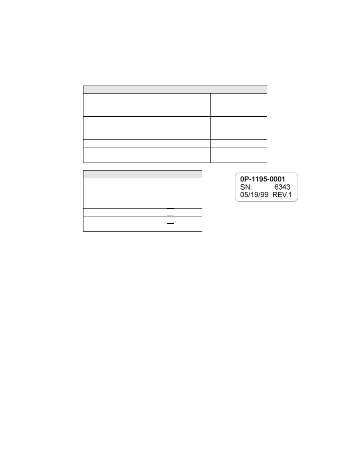
Figure 1: Daktronics Drawing Label
Section 1: Introduction
This manual explains the operation of the Sportsound® Rack (SSR) 300. For additional information
regarding the safety, installation, operation, or service of this system, refer to the telephone numbers
listed in Section 6. This manual is not specific to a particular installation. Project-specific information
takes precedence over any other general information found in this manual.
IMPORTANT SAFEGUARDS:
Please read and understand all instructions before beginning the installation process.
Do not drop control equipment or allow it to get wet.
Do not disassemble control equipment or electronic controls of the system; failure to
follow this safeguard will make the warranty null and void.
Always turn off and/or unplug the control equipment when it is not in use.
Never yank the power cord to pull the plug from the outlet. Grasp the plug and pull to
disconnect.
Do not let any power cord touch hot surfaces or hang over the edge of a table that would
damage or cut the cord. Arrange the cord with care so that it will not be tripped over or
pulled out.
Inspect control equipment for shipping damage such as rattles and dents, and verify that
all equipment is included as itemized on the packing slip. Immediately report any
problems to Daktronics; save all packing materials if exchange is necessary.
1.1 Resources
Figure 1 illustrates a Daktronics
drawing label. The drawing number
is located in the lower-right corner of
a drawing. This manual refers to
drawings by listing the last set of
digits and the letter preceding them.
In the example, the drawing would
be referred to as Drawing C-752494.
Reference drawings in this manual are inserted in alphanumeric order in Appendix A.
This manual may include references to other Daktronics manuals or documents throughout.
Daktronics identifies manuals by the DD or ED number located on the cover page of each
manual. For example, this manual would be referred to as DD2324779.
Daktronics has a searchable knowledgebase of common questions and troubleshooting tips:
www.daktronics.com/support
Visit the Daktronics Support YouTube channel to learn
how to properly operate Sportsound racks:
www.youtube.com/DaktronicsSupport/
Introduction 1
Page 8
Main Component Labels
Part Type
Part Number
Individual circuit board
0P-XXXX-XXXX
Assembly; a collection of circuit boards
0A-XXXX-XXXX
Wire or cable
W-XXXX
Fuse
F-XXXX
Transformer
T-XXXX
Metal part
M-XXX
Fabricated metal assembly
0S-XXXXXX
Specially ordered part
PR-XXXXX-X
Accessory Labels
Component
Label
Termination block for power or
signal cable
TBXX
Grounding point
EXX
Power or signal jack
JXX
Power or signal plug for the
opposite jack
PXX
Figure 2: Typical Label
1.2 Daktronics Nomenclature
Most components within this system carry a white label that lists the part number of the unit.
If a component is not found in the Replacement Parts List in Section 5, use the label to order
a replacement. Figure 2 illustrates a typical label. The part number is in bold.
Following the Replacement Parts List is the Daktronics Exchange Policy and the Repair &
Return Program. Refer to these instructions if replacing or repairing any system component.
2 Introduction
Page 9
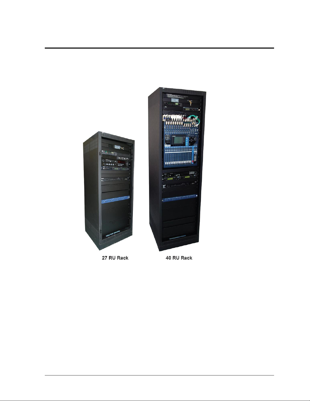
Figure 3: SSR-300 Announcer's Racks
Section 2: SSR-300 Components
2.1 Overview
The SSR-300 announcer’s rack is available in two different sizes: 40 RU and 27 RU (Figure 3).
The SSR-300-40 is 70" (1778 mm) tall, 22" (559 mm) wide, and 25" (635 mm) deep.
The SSR-300-27 is 48" (1219 mm) tall, 22" (559 mm) wide, 20" (508 mm) deep. The
mixer is located remotely from the other rack components, up to 50' (15.2 m) away.
In Appendix A, refer to Drawing B-1102368 for component locations and Drawing
B-1102367 for a detailed wiring schematic.
SSR-300 Components 3
Page 10
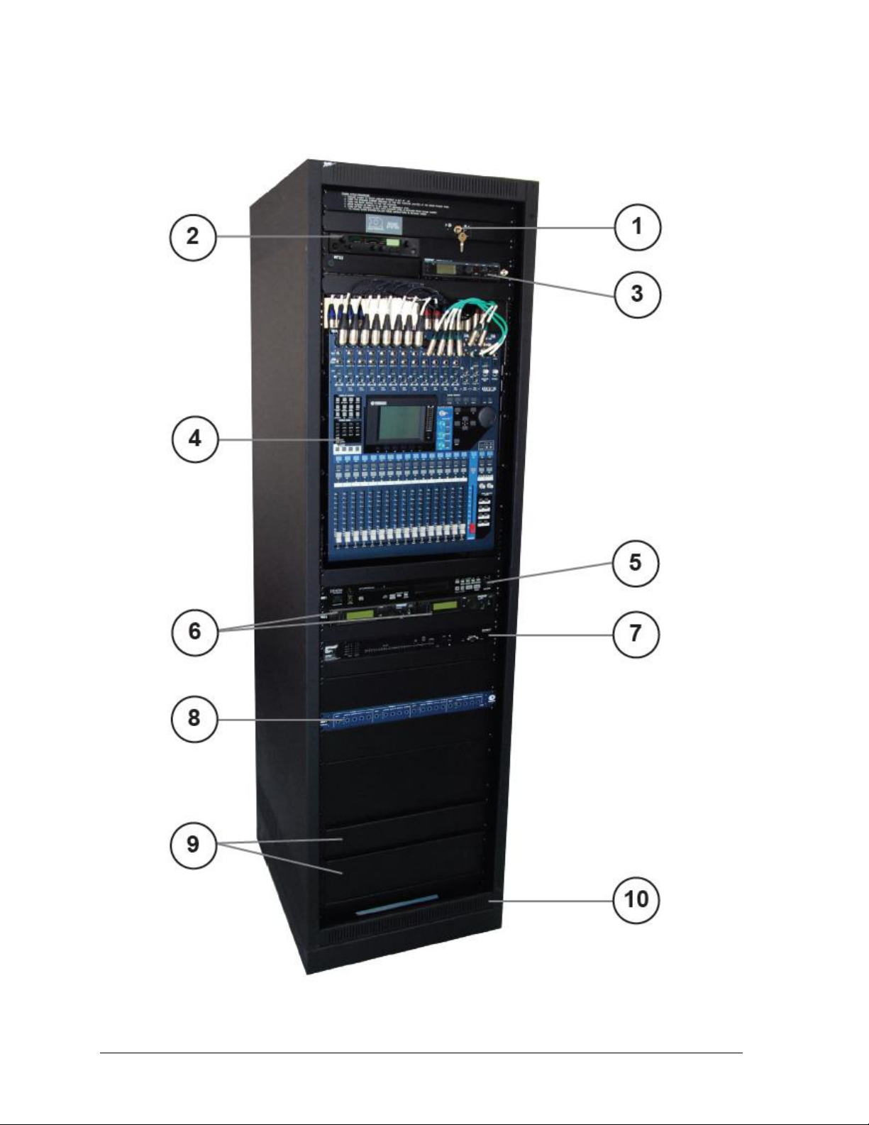
Figure 4: SSR-300-40 Components (door removed)
Figure 4 displays the various announcer’s rack components and how they are arranged.
4 SSR-300 Components
Page 11

#
Component
Reference
Supplementary Manual
1
Sound System ON/OFF Key
N/A
N/A
2
ADA Hearing Assist System
Section
3.10
Listen® LT-800, LR-400 & LA-122 Users Manuals
3
Wireless Personal Stereo
Monitor System
Section 3.9
Shure® PSM®900 Personal Wireless Monitor
System User Guide
4
Audio Mixer
Section 3.5
Yamaha 01V96 Digital Mixing Console Owner’s
Manual
5
Professional CD Player
N/A
DENON Professional CD/Media Player DN-501C
Owner’s Manual
6
Wireless Receiver System
Section 3.7
Shure® ULX® Wireless System User Guide
7
Feedback Reducer
N/A
Shure® Model DFR22 Installation Guide
8
Distribution Amplifier
N/A
ATI DA416 Distribution Amplifier User Manual
9
Storage Drawers
N/A
N/A
10
120 VAC UPS
(Optional, not shown)
N/A
N/A
All supplementary manuals are listed in Appendix B.
SSR-300 Components 5
Page 12
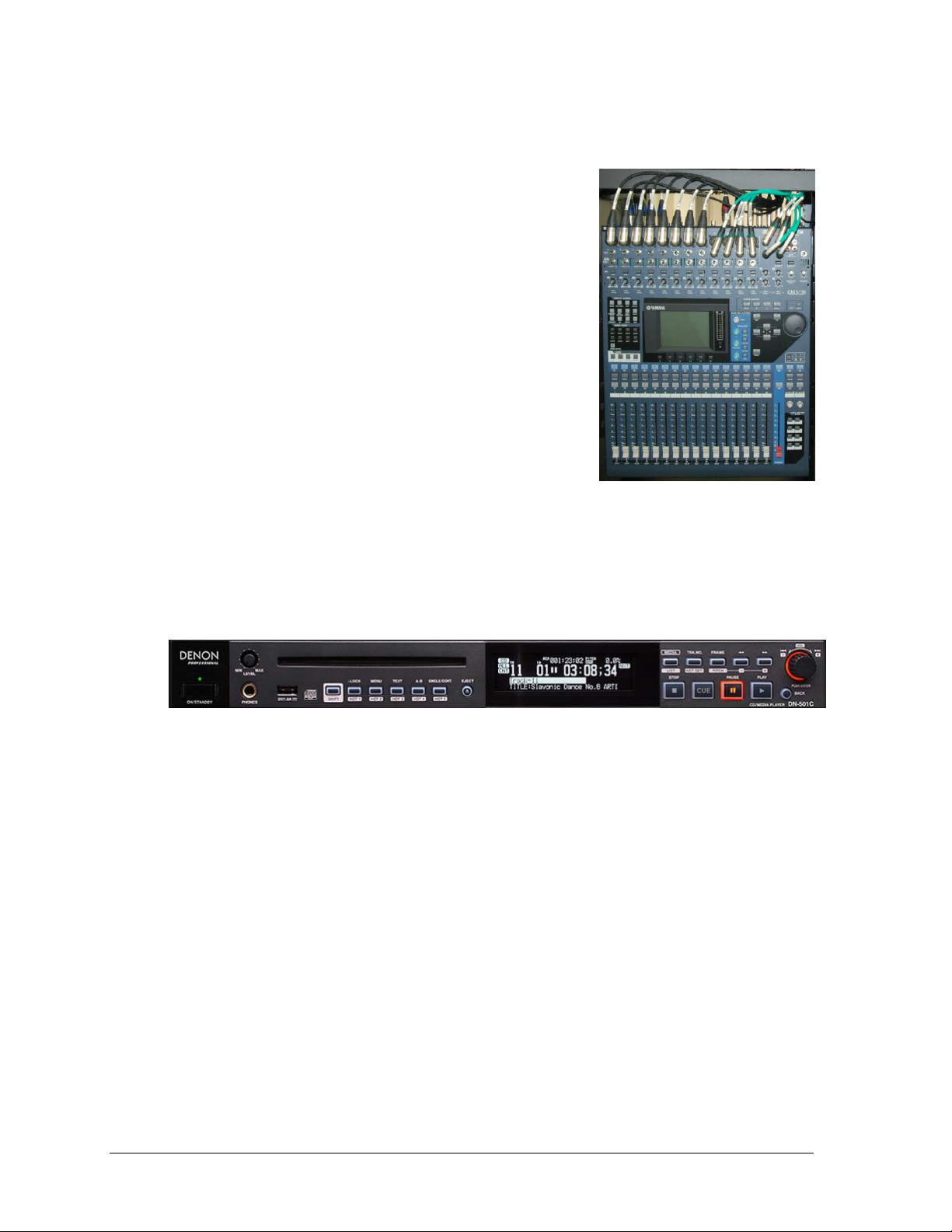
Figure 5: Audio Mixer
Figure 6: Professional CD Player
2.2 Standard Equipment
Audio Mixer
The Yamaha 01V96 Digital Mixer (Figure 5) provides the
performance and reliability of digital live sound in a
compact design. Small but powerful, this mixer handles up
to 40 inputs and offers 24 bit/96 kHz operation for optimum
resolution and quality of sound. Other features include:
Precise 24-bit/96-kHz audio and high-performance
head amps
Up to 40 simultaneous inputs and 20 mix buses in a
compact rack-size mixer
Flexible, independent compression and
gating/ducking processors
Top-performance 24-bit/96kHz effect processors
built-in
Powerful channel functions with flexible control
and digital patching capability
Comprehensive interface with large LCD, 100 mm
motor faders, and dedicated scene memory keys (up to 99 scenes)
Professional CD/Media Player
The DN-501C (Figure 6) is a professional, rack-mount CD/Media Player with a combination
of flexible file formats and comprehensive inputs and outputs. Other features include:
Supports CD-DA/WAV/MP3/AAC/AIFF audio file formats
USB mass storage device playback, including direct digital playback from iPod/iPhone
Balanced analog and digital AES/EBU outputs (XLR)
Unbalanced analog and digital coaxial outputs (RCA)
±16% Pitch Control
IR, RS-232c (9-pin D-sub), and GPIO (25-pin D-sub) controllable
6 SSR-300 Components
Page 13
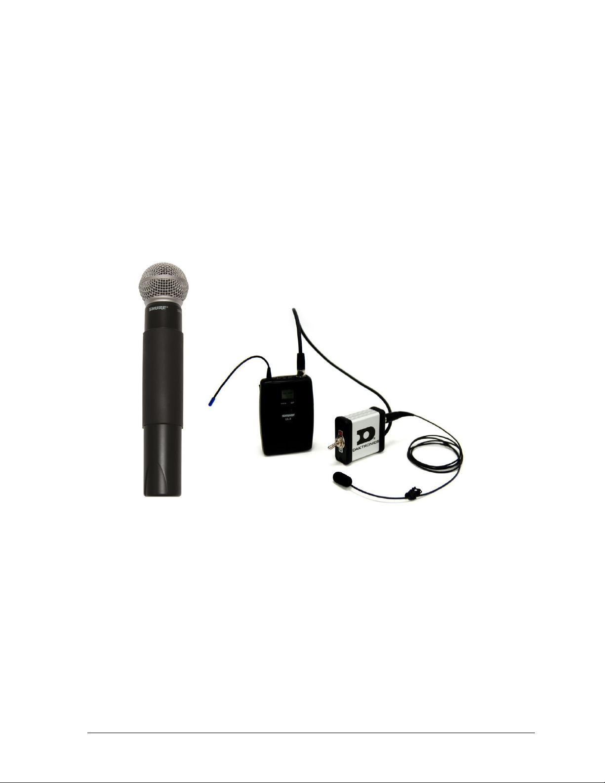
Figure 7: Wireless Microphone & Bodypack Transmitter w/ Mute Switch
Wireless Microphone System
The Shure® ULX® is a professional UHF wireless microphone system. The Sportsound SSR300 Rack is equipped with dual receivers to allow operation of two wireless transmitters
simultaneously (Figure 7). Up to 1400 selectable, pre-programmed frequencies are available.
Automatic Frequency Selection technology detects the clearest frequencies in the area. Other
features include:
Lockable settings
Battery power gauges
Effective Range: 300' (91 m) under optimal conditions
Audio Frequency Response: 25Hz to 15kHz, ±2dB
System Distortion (±38kHz deviation, 1kHz modulation): 0.3% (typical)
RF Sensitivity: 1.26µV for 12 dB SINAD (typical)
Distribution Amplifier
The ATI DA416S Quad Distribution Amplifier is a four-input, sixteen-output distribution
amplifier that accepts four input signals and distributes each input to four individually
adjustable, active balanced outputs. Other features include:
Separate LEDs for each 1x4 channel indicate input signal presence
Phoenix connectors for easy pre-wiring and flexible output channel assignment
Individual wide range audio taper output level controls
SSR-300 Components 7
Page 14
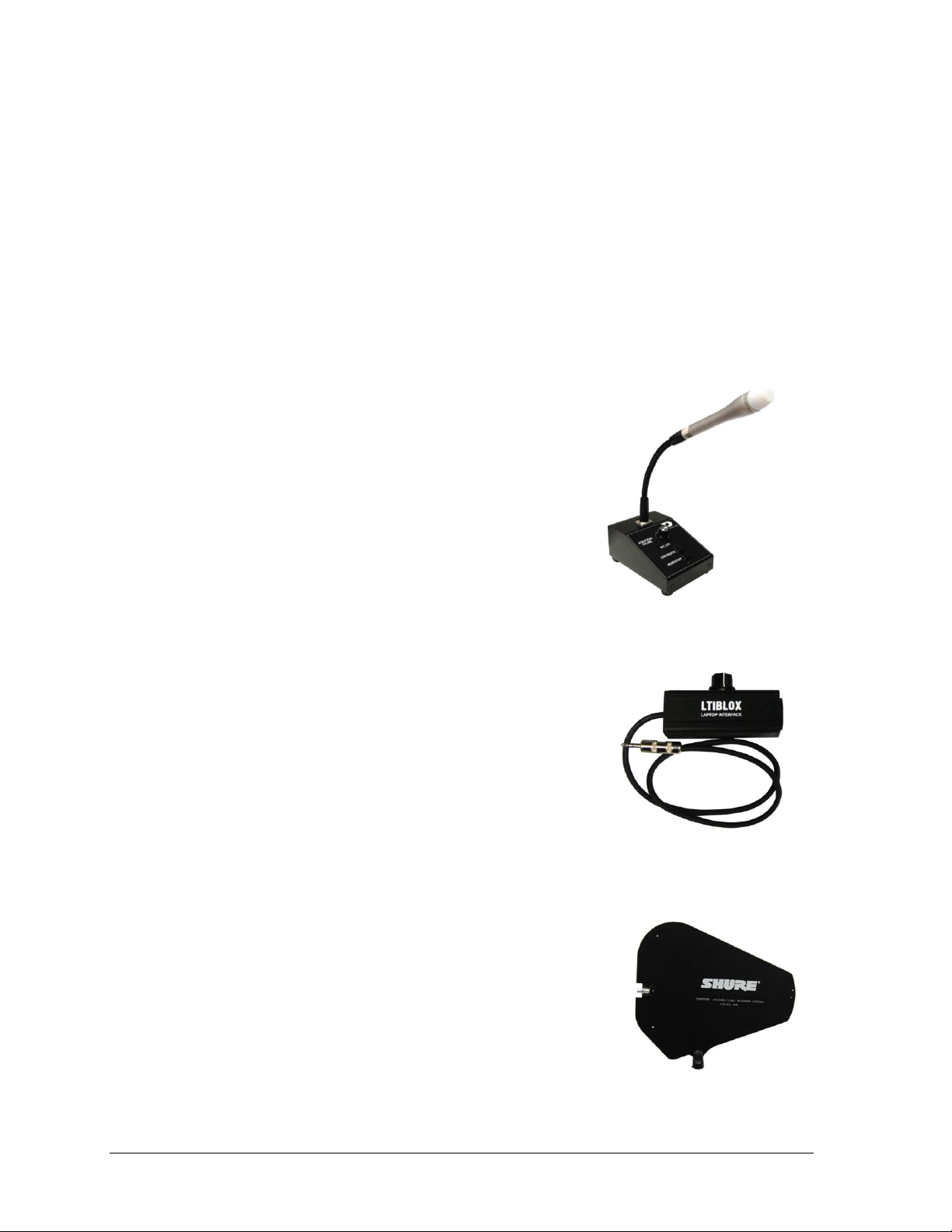
Figure 8: Announcer’s Interface
Figure 9: Laptop Interface
Figure 10: Directional Antenna
Feedback Reducer
The Shure® DFR22 is a two-input, two-output digital audio processor with feedback
reduction. The 2 x 2 matrix mixer allows either or both inputs to be routed to either or both
outputs, with additional controls for levels and polarity. The unit stores sixteen presets and
provides 24-bit conversion, 48kHz sampling and a minimum dynamic range of 100 dB.
Other features include:
Digital feedback reducer, in both mono and stereo processors
Automatic gain control
Parametric and graphic equalizers
Mono & stereo compressor/limiter
Ducker
Two-way crossover & splitter
Subwoofer control
Peak stop limiter
Announcer’s Interface
The Daktronics Announcer’s Interface (Figure 8) includes
one (1) balanced MIC output, one (1) balanced AUX input,
and one (1) headphone jack; headphone volume control
knob; and momentary or continuous microphone activation
buttons. Microphone and headphones are provided.
Laptop Interface
This portable, durable balanced audio converter allows
connection of a laptop or mp3/music player into pro-level
mixers (Figure 9). Other features include:
1/8" (3.5 mm) male input
Balanced XLR male output
Adjustable output volume control
Black powder-coated aluminum chassis
High Gain Antenna Kit
The Shure® PA805 (Figure 10) is a directional antenna for
increased range and reduced interference. The “gain” of this
antenna enables it to receive signals from a greater distance than
at typical “whip” type antenna. The antenna allows for increased
performance of wireless microphones with 6 db of gain. The
directional antennas may be located up to 50' (15.2 m) away from
the announcer’s rack.
8 SSR-300 Components
Page 15

Figure 12: SelfPowered Speaker
Figure 14: Portable FM
Receiver
Figure 11: Single-Muff Headset
Figure 13: USB
Audio Interface
Single-Muff Headset
The professional single-muff headset (Figure 11) may be used
in place of the standard announcer’s interface wired
microphone and headphones. Other features include:
Ambient noise attenuation
Neodymium magnet system for high reproduction
precision
Soft, circumaural ear pads
Cardioid condenser microphone
Self-Powered Monitor Speaker
The Yamaha MSP3 monitor speaker (Figure 12) features a compact bass
reflex cabinet, with a 3.94" (100 mm) two-way cone speaker and a 0.87"
(22 mm) dome speaker. Other features include:
Three inputs: one ¼" phone, one RCA, one XLR
Tone control (High/Low)
USB Audio Interface
The Radial ® Engineering USB-Pro™ (Figure 13) provides an interface
from various input types to balanced outputs. Other features include:
24-bit, 96 kHz quality audio
Two balanced XLR outputs (left and right)
3.5mm TRS headphone output
Ground lift and mono-sum switches
ADA-Hearing Assist System
The Listen® LT-800 Stationary Transmitter allows individuals to
experience every word at an event. This system is designed to broadcast
the audio signal throughout the facility. It is capable of transmitting to
multiple receiver types and its adjustable receivers allow each user to
have full volume control.
SSR-300 Components 9
The Listen LT-400 Portable FM Receiver (Figure 14) provides users with
the choice of 57 channels, a complete antenna, and accessory options
ideal for a wide range of applications. The receivers are digitally tuned so
transmission will not drift.
Page 16

Figure 15: PSM
Receiver
Wireless Personal Stereo Monitor System
The Shure® PSM®900 Wireless in-ear monitor system is used for onfield/on-stage talent. The system allows for personal adjustment of
mix and volume and compensates for delay from the sound system.
Sound travels at 1120' (341 m) per second. This produces a noticeable
delay as one moves away from the speaker. Even experienced
performers have trouble adjusting to this delay. A wireless in-ear
monitor system provides a real-time signal to the talent and blocks the
sound delay from their ears.
Note: If more receivers are required and the transmitter is already
installed, additional receiver packs and headphones are available
to purchase.
2.3 Signal Cables
Cable specifications are as follows:
30' (9.1 m) XLR cable from rack to fiber box or wall plate (part # 0A-1340-0301)
25' (7.6 m) snake cable (part # W-1950) or 50' (15.2 m) snake cable (part # W-1951)
from 27 RU rack to remote mixer
5' (1.5 m) XLR cable for auxiliary audio input (part # W-1627)
15' (4.6 m) XLR cable from announcer’s interface to wall plate (part # W-2074)
25' (7.6 m) XLR cable for connecting additional wired microphones (part # W-1560)
10 SSR-300 Components
Page 17

Figure 16: Power Key Switch
Section 3: Setup & Operation
3.1 Power & Signal Connections
All connections are made upon installation. Some equipment may be connected and
disconnected each time it is used. Drawing C-1102369 in Appendix A shows a general
overview of how standard and optional equipment connects to the rack. Note that every
project is unique, so be sure to follow any site-specific riser drawings and documentation for
the facility to determine the exact layout of system components.
3.2 Setup
The announcer’s interface equipment is typically kept in the bottom storage drawers along
with other accessories. Follow the steps below to properly reconnect it to the rack.
1. Connect one end of the XLR gooseneck to the wired microphone and the other end
into the jack on top of the announcer’s interface. Also plug the wallpack transformer
into a standard power outlet.
Note: The headset microphone may be connected to the announcer’s interface via the
XLR jack and the HEADPHONES jack (on rear).
2. Connect the 15' (4.6 m) XLR cable (part # W-2074) from MIC 1 & AUX 1 on the
announcer’s interface to Mic 1 & Aux 1 on the announcer’s plate.
For the 27 RU rack only, there will be a 25' (7.6 m) or 50' (15.2 m) cable harness factory wired
to the rack. Route this cable to the desired mixer location and connect each plug to the
appropriate jack on the mixer according to the wire labels. Plug the mixer into a standard
power outlet.
3.3 Powering ON
Unlock the door of the rack, and turn the SOUND SYSTEM key switch (Figure 16) to the
ON (vertical) position.
Note: Keep both sets of keys in a safe location to prevent tampering/theft of rack equipment!
Setup & Operation 11
Page 18

Figure 17: OFF Key
Figure 18: GAME Key
Figure 19: Gain Knobs & PEAK/SIGNAL Indicators
3.4 Powering Down
3. Press the USER DEFINED KEY on mixer labeled OFF
(Figure 17).
4. Turn the SOUND SYSTEM key switch to the OFF
(horizontal) position.
5. If the system will not be used for some time, unplug the
power cord.
6. Place all accessories back in the appropriate slots of the
storage drawers to keep them safe and organized.
7. Close and lock the rack door.
3.5 Mixer Operation
Basic instructions are described below. For more information about
audio mixer operation, refer to the Yamaha 01V96 Digital Mixing
Console Owner’s Manual.
1. Press the USER DEFINED KEY labeled GAME
(Figure 18).
Note: Custom keys (presets) may have been set up during
training. Press the desired key as needed for a specific
application. The creation of additional presets is
recommended for advanced users only.
2. Ensure all source equipment is turned on and operational (refer to the appropriate
sections of this manual and/or manufacturers’ manuals).
3. Verify gain knobs for the channels in use are adjusted so the SIGNAL light is green
and the PEAK light is not lit (Figure 19).
12 Setup & Operation
Page 19

Figure 20: Channel & SOLO Buttons
Figure 21: Channel Sliders
Figure 22: Output Meter
4. Ensure the ON buttons for the channels in use and for the STEREO slider are
illuminated; also verify no SOLO buttons are illuminated (Figure 20).
5. Bring sliders up slowly and listen for the signal (Figure 21).
6. The signal should be visible on the STEREO output meter
(Figure 22):
The amber LEDs indicate that the level is near clip.
The red LEDs indicate that the signal has reached the
digital limit.
REMEMBER: Bad input = bad output. No adjustment on the mixer
can make a poor source sound better. For best results, be sure to
use high-quality audio files from your MP3 player or laptop, and
set the device to near full volume.
Setup & Operation 13
Page 20

3.6 Announcer’s Interface Operation
Refer to Figure 23 for locations of the following controls and jacks.
1. XLR input jack - connect gooseneck or headset microphone
2. HEADPHONE VOLUME – Turn this knob clockwise to increase and counter-
clockwise to decrease headphone volume.
3. MIC LIVE – This LED indicator lights up when the microphone is live.
4. CONTINUOUS – Press this button once to activate the microphone and turn on the
MIC LIVE indicator. Press this button again to deactivate the microphone and turn
off the MIC LIVE indicator.
5. MOMENTARY – Hold down this button to activate the microphone. Release this
button to deactivate the microphone. The MIC LIVE indicator will remain on as long
as the button is pressed.
6. HEADPHONES – ¼" jack for headphones (or single-muff headset)
7. MIC 1 – XLR output jack to audio mixer
8. AUX 1 – XLR input jack from audio mixer
9. POWER INPUT – plug in provided 24 VDC wallpack transformer
10. MIC ONLY/MIXED AUDIO – Located on the bottom of the console, this switch
determines whether the announcer can hear only their microphone or all audio
sources through the headphones. Leave this set to MIXED AUDIO.
14 Setup & Operation
Page 21

Figure 23: Announcer's Interface Controls & Jacks
Setup & Operation 15
Page 22

Figure 24: Wireless Receiver LCD & Controls
3.7 Wireless Mic System Operation
Basic instructions are described below. For more information about wireless mic system
operation, refer to the Shure® ULX® Wireless System User Guide.
Wireless Receiver
1. Ensure all transmitters are powered off. Flip the power on/off switch to turn on one
receiver if it is not already on.
The unit can display the following information (Figure 24):
a) Group Number
b) Channel Number
c) Transmitter Battery Life
d) RF Signal Strength
e) Transmitted Audio Signal Strength
f) Frequency
2. Hold the SET button and then press MODE once. The word SCAN will appear on
the display. To begin scanning, simply rotate the control knob clockwise. When all
groups have been scanned, the group with the most open channels will appear. Press
SET to accept the recommended GROUP and assign the clearest CHANNEL.
3. Turn on the second receiver unit. Press MODE twice and use the control knob to
select the same GROUP as the first receiver. Press SET and select a different
CHANNEL than the first receiver. The next highest number should work, but it may
be necessary to select another. Press SET again to save the settings.
Note: Perform a scan on all of the wireless units just minutes before the game! If a
scan is performed too far ahead of time, frequencies set up by the media later on may
interfere with previously configured wireless microphone settings.
16 Setup & Operation
Page 23

Figure 25: Wireless Mic & Bodypack Controls
Wireless Mic & Bodypack Operation
1. Open the battery cover. Insert new or fully-charged 9V batteries prior to each use,
and always have spares on hand.
2. Power on the device (Figure 25). Note that with the handheld mic, you must remove
the protective sleeve to access the power and control buttons. Hold MODE until only
the GROUP number is visible. Use SET to select the same group number as the first
receiver unit. Press MODE to continue.
3. Use SET to select the same CHANNEL number as the first receiver unit and then
press MODE to save the settings.
4. Repeat steps 1-3 with the second transmitting device, using the GROUP and
CHANNEL settings of the second receiver unit.
Note: Plug the mic switch into the jack on top of the bodypack unit and plug
headphones/lapel mic into the mic switch.
Verify Reception: With a transmitter and the receiver both turned on and having matching
GROUP and CHANNEL numbers, the RF meter on the receiver should be indicating signal.
Speak into the microphone and the TX AUDIO meter should indicate signal presence.
Setup & Operation 17
Page 24

3.8 Microphone Best Practices
Keep handheld microphones 4-6 inches (102-152 mm) from the mouth (about the width
of a hand).
“P-pops” are loud sounds created by the release of breath when saying letters like “p” or
“b”. To avoid P-pops, keep handheld microphones below the mouth, angled toward the
nose at a 45° angle. Do not point the front of the microphone straight at the mouth.
Position headset microphones as close to the mouth as comfortable.
The referee bodypack kit includes both headset and lapel microphones. In general it is
recommended to use the headset mic for best results. If the lapel mic is desired, clip it
onto a lapel, as close to the center of the chest as possible.
The softer or louder the speaker’s voice, move the microphone closer or further away,
respectively.
Never hit or intentionally blow into a microphone as it could quite easily be damaged.
3.9 Personal Monitor System Operation
Basic instructions are described below and shown in Figure 26. For more information, refer to
the Shure® PSM®900 Personal Wireless Monitor System User Guide.
1. Flip the transmitter POWER switch to ON if it is not already on; ensure the RF
switch to the left of it is OFF at this time.
2. Power on the handheld receiver using the volume knob.
3. Attach the antenna and earphones to the top of the handheld receiver.
4. Flip open the battery cover to expose the control buttons. Press SCAN and the
display will show “SYNC NOW”.
Note: Insert new or fully-charged batteries prior to each use, and always have spares
on hand.
5. Hold the bodypack up to the transmitter with the sync IR windows facing each other,
and press the SYNC button on the transmitter. The display will show “SYNC
SUCCESS” when finished.
6. Flip the transmitter RF switch to ON. The blue LED on the receiver should illuminate
to indicate that it is detecting the transmitter.
18 Setup & Operation
Page 25

Figure 26: Optional Personal Stereo Monitor System
Setup & Operation 19
Page 26

Figure 27: Optional Hearing Assist System
3.10 Hearing Assist System Operation
Basic instructions are described below and shown in Figure 27. For more information, refer to
the Listen® LT-800 Stationary Transmitter, Listen® LR-400 FM Receiver, and Listen® LA-122
Universal Antenna Kit Users Manuals.
1. Press POWER to turn on the transmitter if it is not already on.
2. Use the CHANNEL SELECT buttons to select a channel.
3. Plug the earphones into the jack on top of the handheld receiver.
4. Rotate the volume dial counterclockwise to power on the handheld receiver.
5. Flip open the battery cover to expose the control buttons. Use the CHANNEL
SELECT buttons to select the same channel that was set on the transmitter, or press
SEEK to locate the active channel.
Note: Insert new or fully-charged batteries prior to each use, and always have spares
on hand.
6. Repeat steps 3-5 for any additional receivers.
20 Setup & Operation
Page 27

Symptom/Condition
Possible Cause
Potential Solution
Announcer’s microphone signal does
not appear at mixer
Announcer’s interface does
not have power
Verify the interface is
plugged into the wall
Announcer’s interface is not
plugged into appropriate
inputs on the announcer’s
interface plate
Plug announcer’s interface
into AUX 1 and MIC 1 on the
announcer’s interface plate
(part # EN-2416)
Improper mixer slider settings
for MIC 1
Adjust mixer slider settings
No phantom power from
mixer
Turn on phantom power
from mixer
The announcer’s interface
“press to talk” button is not
being pressed
Hold the “MOMENTARY”
button while speaking into
the microphone
Announcer only hears self through
headphones
Switch on the bottom of the
announcer’s interface is set
to MIC ONLY
Move switch to MIXED
AUDIO
Section 4: Maintenance and Troubleshooting
4.1 Maintenance
Unplug rack and fiber box from power during periods of non-use.
Store equipment in a clean dry place free from moisture, debris, and extreme temperatures.
Keep announcers rack and equipment covered from dust and debris when not in use.
Clean equipment annually or as needed using electronic equipment duster and a dry cloth.
4.2 Troubleshooting
This section lists potential problems with the system, indicates possible causes, and suggests
corrective action. This list does not include every possible problem, but it does represent
some of the more common situations that may occur. If individual components fail to work,
refer to troubleshooting sections in the manufacturers’ manuals. If the problem persists,
please contact Daktronics for assistance.
Note: Be sure to power on the announcer’s rack, fiber box, and cabinet breakers.
Make sure all connections from source to the fiber box are complete.
Maintenance & Troubleshooting 21
Page 28

Symptom/Condition
Possible Cause
Potential Solution
Announcer hears nothing through
headphones
Announcer’s interface is not
plugged into appropriate
inputs the announcer’s
interface plate
Plug announcer’s interface
into AUX 1 and MIC 1 on the
announcer’s interface plate
(part # EN-2416)
AUX 1 settings are
improperly set on mixer
Check MIC 1 and AUX 1
mixer settings
Announcer’s interface
HEADPHONE VOLUME is
turned down
Turn HEADPHONE
VOLUME knob to an
appropriate level
Announcer’s mic muting circuit does
not work
No phantom power from
mixer
Turn on phantom power
from mixer
For Wireless
No signal present at mixer from
wireless microphones
The battery is not installed
properly in the transmitter
Reinstall the battery properly
The battery is not providing
full power
Charge or replace battery
The transmitter is not
switched to the on position
Switch the transmitter to the
on position
The transmitter and receiver
are set to different channels
Set to same channel
Interference on wireless equipment
Competing RF equipment
within frequency band
1. Scan for clearest
group/channel on
microphone receiver.
2. Switch wireless receiver
and transmitter to an
available clear channel.
(Section 3.7)
Low audio signal from wireless
device
Improper gain adjustment on
mixer input
Set proper mixer input gain
levels
Improper gain adjustment on
transmitter output
Set proper transmitter output
gain levels (refer to Shure®
ULX® Wireless System
User Guide)
22 Maintenance & Troubleshooting
Page 29

Part Description
Part Number
Announcer’s Interface
3-Pin Announcers Interface
0A-1534-0010
Dynamic Vocal Microphone
A-1953
Headphones, ¼" Phone
A-1962
12" Black Gooseneck, XLR M to F
A-3073
Wallpack Transformer, 12VAC; 6' Cord
T-1118
15’ Cable, Announcer Box to Mixer
W-2074
System Switch Panel
0A-1340-2028
High Gain Antenna Kit
0A-1340-0325 &
0A-1340-0326
Passive Directional Antenna, 470-952 MHz
A-3124
50’ Coaxial Antenna Cable w/ BNC
W-2476
Middle Atlantic PD-2415SC; 24 Outlet Power Strip (40 RU Model Only)
A-1937
Referee Headset Microphone
A-1972
Listen ADA Hearing Assist Transmitter/Receiver Kit
A-2016
In Ear Speaker (4 included in kit)
A-1908
FM Receiver (4 included in kit)
A-2050
Yamaha Digital Mixing Console (01V96)
A-2027
Telex Wall Plate Microphone (WP300)
A-2082
Yamaha Self-Powered Monitor Speaker
A-2206
Shure DFR22 Audio Processor with Feedback Reduction
A-2261
DENON DN-501C CD Player
A-2262
Single Muff Microphone Headset
A-2382
Condenser Microphone
A-2474
USB Audio Interface
A-2493
Shure PSM900 Personal Monitor System; Band L6 – 656-692 MHz
A-2719
Transmitter
A-2720
Bodypack Receiver
A-2721
Section 5: Replacement Parts
5.1 SSR-300 Components
Replacement Parts 23
Page 30

Shure PSM900 Personal Monitor System; Band K1 – 596-632 MHz
A-2722
Transmitter
A-2723
Bodypack Receiver
A-2724
Middle Atlantic PD-91R; 9 Outlet Power Strip (27 RU Model Only)
A-2740
LTIBLOX Laptop Interface
A-2755
Shure Wireless Bodypack Package For G3 Band
A-3115
Shure Wireless Bodypack Package For J1 Band
A-3116
Shure Wireless Bodypack Package For M1 Band
A-3117
Shure Wireless Microphone Handheld Package For G3 Band
A-3118
Shure Wireless Microphone Handheld Package For J1 Band
A-3119
Shure Wireless Microphone Handheld Package For M1 Band
A-3120
Shure Wireless Accessories
Passive Antenna Combiner
A-3121
Black Cloth Pouch for ULX1
A-3123
Referee Mute Switch
A-3122
ATI Quad Distribution Amplifier (DA416S)
A-3235
Media Panel Jack Plate
EN-2156
Announcer’s Interface Plate
EN-2416
Cable, 25’ XLR M to F
W-1560
Cable, 5’ XLR M to F
W-1627
Part Description
Part Number
UPS; 120 VAC, SMARTRM, 1000VA
A-2360
5.2 Optional Components
24 Replacement Parts
Page 31

Market Description
Customer Service Number
Schools (including community/junior colleges), religious
organizations, municipal clubs and community centers
877-605-1115
Universities and professional sporting events, live events
for auditoriums and arenas
866-343-6018
Section 6: Daktronics Exchange and Repair &
Return Programs
6.1 Exchange Program
The Daktronics Exchange Program is a service for quickly replacing key components in need
of repair. If a component fails, Daktronics sends a replacement part to the customer who, in
turn, returns the failed component to Daktronics. This decreases equipment downtime.
Customers who follow the program guidelines explained below will receive this service.
Before Contacting Daktronics
Identify these important numbers:
Model Number: ________________________________________________________________
Job/Contract Number: __________________________________________________________
Date Manufactured/Installed: ___________________________________________________
Daktronics Customer ID Number: ________________________________________________
To participate in the Exchange Program, follow these steps.
1. Call Daktronics Customer Service.
2. When the new exchange part is received, mail the old part to Daktronics.
If the replacement part fixes the problem, send in the problem part being replaced.
a. Package the old part in the same shipping materials in which the replacement
part arrived.
b. Fill out and attach the enclosed UPS shipping document.
c. Ship the part to Daktronics.
3. The defective or unused parts must be returned to Daktronics within 5 weeks of
initial order shipment.
If any part is not returned within five (5) weeks, a non-refundable invoice will be
presented to the customer for the costs of replenishing the exchange parts inventory
with a new part.
Daktronics reserves the right to refuse parts that have been damaged due to acts of
nature or causes other than normal wear and tear.
Daktronics Exchange and Repair & Return Programs 25
Page 32

6.2 Repair & Return Program
For items not subject to exchange, Daktronics offers a Repair & Return Program. To send a
part for repair, follow these steps:
1. Call or fax Daktronics Customer Service:
Refer to the appropriate market number in the chart listed on the previous page.
Fax: 605-697-4444
2. Receive a case number before shipping.
This expedites repair of the part.
3. Package and pad the item carefully to prevent damage during shipment.
Electronic components, such as printed circuit boards, should be placed in an
antistatic bag before boxing. Daktronics does not recommend using packing
‘peanuts’ when shipping.
4. Enclose:
name
address
phone number
the case number
a clear description of symptoms
Shipping Address
Daktronics Customer Service
[Case #]
201 Daktronics Drive, Dock E
Brookings, SD 57006
6.3 Daktronics Warranty and Limitation of Liability
The Daktronics Warranty and Limitation of Liability is located in Appendix C. The Warranty
is independent of Extended Service agreements and is the authority in matters of service,
repair, and display operation.
26 Daktronics Exchange and Repair & Return Programs
Page 33

Appendix A: Reference Drawings
Drawing Title Drawing Number
Schematic; Sportsound Rack 300 .......................................................................................... B-1102367
Rack Layout; Sportsound Rack 300 ....................................................................................... B-1102368
Installation Riser; Sportsound Rack 300 ................................................................................. C-1102369
Reference Drawings 27
Page 34

Page 35

ALL CONNECTIONS FROM
MIXER TO CARDS ARE WITH
MIXER HARNESS
(W-1949/W-1950/W-1951)
OP1
OP1
PWS2 POWER STRIP TO ALL
EQUIPMENT
LABELS
0A-1340-2029
EN-2156
ADA1-OP1'S ADA1-OP2'S ADA1-OP3'S
EN-2156 EN-2156
EC-1021
POWER-JBOX
JB01
S-1215
SYSTEM_RPS
SWT1
ANT2
0A-1340-2028
(USE EC-1033 'J-BOX' WHEN
MOUNTING)
RACK PACKETS
0A-1340-2042
0A-1340-2043
0A-1340-2044
0A-1340-2045
0A-1340-2046
0A-1340-2047
0A-1340-2048
0A-1340-2049
0A-1340-2050
OP9T OP10T OP11 OP13OP12 OP14 OP15 OP16 IP9T IP10T IP11 IP12 IP13 IP14 IP15 IP16
LINE INLINE OUT
INSRT9
INSRT10
INSRT9 INSRT10
INSERT INSERT
TERMINATION
MADE ON SITE
PLUG IN OP9T-OP16 WITH
SUPPLIED MIXER HARNESS
TERMINATE TO
ASE1
LEAVE IP11-IP14
UNTERMINATED
ADA1-OP4'S
EN-2156
YAMAHA/01V-CA
IP1 ANNC.
IP2 MIC2
IP3 MIC3
IP4 HAND
OP AUX 1
OP AUX 2
OP AUX 3
OP AUX 4
IP7
IP5 REF
IP6
IP9 VID 1
IP8 CROWD
OP ST L
OP ST R
OP MNTR L
OP MNTR R
IP10 VID 2
IP11
IP12
IP13 IPOD
IP14 TAPE
IP15 CD L
IP16 CD R
A-2027
O
M
N
I
OP AUX 1
OP AUX 2
OP AUX 3
OP AUX 4
M
Y
4
D
A
MIX1
CH1
CH2
CH3
CH4
CH5
CH6
CH7
CH8
CH9
CH10
CH11
CH12
CH13
CH14
CH15
CH16
AUX1
AUX2
AUX3
AUX4
AUX5
AUX6
AUX7
AUX8
STL
STR
MONL
MONR
SHURE/DFR22
IP1 OP1
OP2
A-2261
IP2
DSP1
A005
A006
A007
A008
W-1917
0A-1340-2018
0A-1340-0076
0A-1340-0076
LISTEN/LS-03-216
IPL ANT
A-2016
WTX1
A022
0A-1340-0075
INCLUDED
AUX OUT
0A-1340-0218
CH3
CH4
CH5
CH6
CH7
CH8
CH2
CH1
BOP2
AUX1
AUX2
AUX3
AUX4
AUX5
AUX6
AUX7
AUX8
A030
A021
A022
A023
A024
A025
A026
W-1614R
W-1615
W-1615
W-1615
W-1615
LINE IN
0A-1340-0217
CH11
CH12
CH13
CH14
CH15
CH16
CH10
CH9
CH9 INS
CH10 INS
BOP4
A011
A014
A015
A016
A019
CH9
CH10
CH11
CH12
CH13
CH14
CH15
CH16
A016
A019
W-1615
W-1615
W-1615
MIC IN
0A-1340-0216
CH3
CH4
CH5
CH6
CH7
CH8
CH2
CH1
BOP3
A031
A032
A033
A007
A008
A013
CH1
CH2
CH3
CH4
CH5
CH6
CH7
CH8
W-1614B
W-1614B
W-1614R
W-1615
ANT A MIC OUT
SHURE ULXP4
ANT B
HIGH Z OUT
PWR IN
WRX1
A-3118/A-3119/A-3120
A003
A009
A005
W-1917
ANT A MIC OUT
SHURE ULXP4
ANT B
HIGH Z OUT
PWR IN
WRX2
A-3115/A-3116/A-3117
A004
A010
A006
0A-1340-2018
CD PLAYER
XLR L
XLR R
ASE1
A-2262
A014
A015
0A-1340-0076
0A-1340-0076
HEADPHONES AUX1
ANNOUNCER'S INTERFACE
MIC MIC1
T-1118
12VAC
PWR
0A-1534-0069
MIC1
W-2074-MIC
W-2074-AUX
0A-1534-0010
ANNCR'S PLATE
AUX1
MIC1
MIC2
EN-2416
MIC3
JBT1
A030
A031
A032
A033
W-2074
W-2074
W-1614R
W-1614B
W-1614B
W-1614R
SHURE PSM900
IP1
IP2
LOOP OUT L
LOOP OUT R
ANTENNA
WTX2
A-2719/A-2722
A021
0A-1340-0075
W-2476
YAMAHA/MSP3-CA
A-2206
SPK01
A029
TERMINATION
MADE ON SITE
W-1615
SHURE UA221
ANT R1
R2
SPLITTER
A001
A003
A004
SHURE UA221
ANT R1
R2
SPLITTER
A002
A009
A010
INCLUDED WITH A-3121 SPLITTERS- INSTALLED IN FACTORY
CONNECT ANTENNA ON SITE
IN BEST FIELD LOCATION,
USING THIS ORIENTATION
HIGH GAIN ANTENNA KIT
0A-1340-0325
W-2476
50' ANTENNA
CABLES @2
INCL.
A-3124
ANT1
A-3124
HIGH GAIN ANTENNA KIT
0A-1340-0326
A-3124
ANT3
W-2476
50' ANTENNA
CABLE INCL.
ANT4
W-1614@2
FIELD INSTALLED
P-1227
POWER CORD CUT
FROM POWER STRIP
MA/PD-915R
INPUT
OUTPUT
OUTPUT
OUTPUT
OUTPUT
OUTPUT
OUTPUT
OUTPUT
OUTPUT
PWS2
A-2740
MA/PD-915R
INPUT
OUTPUT
OUTPUT
OUTPUT
OUTPUT
OUTPUT
OUTPUT
OUTPUT
OUTPUT
PWS3
A-2740
INCLUDED IN 0A-1340-0337
THE CONCEPTS EXPRESSED AND DETAILS SHOWN ON THIS
DRAWING ARE CONFIDENTIAL AND PROPRIETARY. DO NOT
REPRODUCE BY ANY MEANS WITHOUT THE EXPRESSED
WRITTEN CONSENT OF DAKTRONICS, INC.
COPYRIGHT 2010 DAKTRONICS, INC.
DAKTRONICS, INC.
BH
DRAWN: DATE:
SHEET JOB NO:REV
SPORTSOUND SYSTEMS
SCHEMATIC; SPORTSOUND RACK 300
JWCARLSO 15 JUN 12
P1340 R
03 B
NONE
JWCARLSO
1102367
02
DATE:REV BY:
01 11 JAN 13 JWC
REPLACED A-2118 WITH A-3235 AUDIO DISTRIBUTION AMPLIFIER
SOUND CARD
USB
LEFT OUT
RIGHT OUT
A-2493 R01
USB1
A011
INCLUDED
W-1615
J-1125 @1 FOR END
DATE:REV BY:
02 4 SEP 13 KCS
UPDATED SOUND CARD A-2493 BLOCK PER EC-11519
ST L
ST R
MON L
MON R
ST IN R ST OUT R
ST OUT L
ST OUT R
SYSTEM OUT
0A-1340-0219
MON IN L
MON IN R
MON OUT L
MON OUT R
ST IN L ST OUT L
BOP1
A029
A028
ATI/DA416S
IP A
OP B1
OP B2
OP A1
OP A2
OP A3
OP A4
OP B3
OP B4
IP B
OP C1
OP C2
IP C
OP C3
OP C4
OP D1
OP D2
OP D3
OP D4
IP D
ADA1
A023
A024
A025
A026
W-1615
W-1615
W-1615
W-1615
W-1614
W-1614
W-1614
W-1614
A-3235
Page 36

SHURE
SET
POWER
SHURE
SET
POWER
SHURE
SET
POWER
SHURE
SET
POWER
ON
OFF
115 VOLT
15 AMP
60 HZ
POWER CENTER PD-915R
MASTER
ON
OFF
115 VOLT
15 AMP
60 HZ
POWER CENTER PD-915R
MASTER
DATE:REV BY:
01 10 JAN 13 JWC
REPLACED A-2118 WITH A-3235 AUDIO DISTRIBUTION AMP
A
1 2 3 4
B
4321
D
4321
C
1 2 3 4
Quad Distribution Amplifier
Encore Series
DA416
A
1 2 3 4
B
4321
D
4321
C
1 2 3 4
Quad Distribution Amplifier
Encore Series DA416
DATE:REV BY:
02 24 OCT 13 KCS
REMOVED EN-2288 FROM THE REAR OF THE RACK
PER EC-11519
Page 37

&+
5()(57262:''
6&+(0$7,&':*
ANNCR
MEDIA PANEL
+6 BALANCED
REFCROWD
PROGRAM
Mic 2
Mic 1
Aux 1
Mic 3
HEADPHONE
VOLUME
MIC LIVE
CONTINUOUS
MOMENTARY
Mic 2
Mic 1
Aux 1
Mic 3
HEADPHONE
VOLUME
MIC LIVE
CONTINUOUS
MOMENTARY
'$.7521,&6,1&
'$.7521,&6$8',2+'
5(3/$&('0$8',26281'&$5'$:,7+
'$7(5(9 %<
6(3 .&6
5$',$/3$573(5(&
,167$//$7,215,6(5632576281'5$&.
-:&
121(
6+((7 -2%125(9
'5$:1 '$7(
3 5 &
MEDIA PANEL
REFCROWD
ANNCR
PROGRAM
+6 BALANCED
7+(&21&(376(;35(66('$1''(7$,/66+2:1217+,6
'5$:,1*$5(&21),'(17,$/$1'35235,(7$5<'2127
5(352'8&(%<$1<0($16:,7+2877+((;35(66('
:5,77(1&216(172)'$.7521,&6,1&
&23<5,*+7'$.7521,&6,1&
-:& -81
Page 38

Page 39

Component
Model #
Manufacturer’s Manual
Audio Mixer
01V96
Yamaha
www.yamaha.com
Professional CD Player
DN-501C
Denon
www.denon.com
Wireless Receiver
System
ULX
Shure
www.shure.com
Directional Antenna
PA805
Shure
www.shure.com
Wireless Personal
Stereo Monitor System
PSM900
Shure
www.shure.com
Feedback Reducer
DFR22
Shure
www.shure.com
Distribution Amplifier
DA416S
ATI
www.atiaudio.com
Stationary FM
Transmitter
LT-800
Listen
www.listentech.com
Portable FM Receiver
LR-400
Listen
www.listentech.com
Universal Antenna Kit
LA-122
Listen
www.listentech.com
USB Audio Interface
USB-Pro
Radial Engineering
www.radialeng.com
Appendix B: Supplementary Manuals
Manuals for all standard and optional components are shipped along with the audio system.
If any product manuals are missing, lost, or damaged, visit the manufacturer’s website or
perform a web search for the component model number.
When viewing a digital copy of this manual (at www.daktronics.com/manuals), click on the
appropriate manufacturer link below to view a component’s manual. If the link is broken,
visit the manufacturer’s website or perform a web search for the component model number.
Supplementary Manuals 29
Page 40

Page 41

Appendix C: Daktronics Warranty and Limitation
of Liability
Daktronics Warranty and Limitation of Liability 31
Page 42

Page 43

Copyright © Daktronics, Inc. SL-02374 Rev 10 02-Mar-2009 Page 1 of 2
DAKTRONICS
WARRANTY AND LIMITATION OF LIABILITY
This Warranty and Limitation of Liability (the “Warranty”) sets forth the warranty provided by Daktronics with respect to the Equipment. By
accepting delivery of the Equipment, Purchaser agrees to be bound by and accept these terms and conditions. All defined terms within
the Warranty shall have the same meaning and definition as provided elsewhere in the Agreement.
DAKTRONICS WILL ONLY BE OBLIGATED TO HONOR THE WARRANTY SET FORTH IN THESE TERMS AND CONDITIONS UPON RECEIPT OF FULL
PAYMENT FOR THE EQUIPMENT.
1. Warranty Coverage
2. Exclusion from Warranty Coverage
A. Daktronics warrants to the original end-user that the Equipment will be free from Defects (as defined below) in materials and
workmanship for a period of one (1) year (the “Warranty Period”). The warranty period shall commence on the earlier of: (i) four
weeks from the date that the equipment leaves Daktronics’ facility; or (ii) Substantial Completion as defined herein. The warranty
period shall expire on the first anniversary of the commencement date.
“Substantial Completion” means the operational availability of the Equipment to the Purchaser in accordance with the
Equipment’s specifications, without regard to punch-list items, or other non-substantial items which do not affect the operation of
the Equipment.
B. Daktronics’ obligation under this Warranty is limited to, at Daktronics’ option, replacing or repairing, any Equipment or part
thereof that is found by Daktronics not to conform to the Equipment’s specifications. Unless otherwise directed by Daktronics,
any defective part or component shall be returned to Daktronics for repair or replacement. Daktronics may, at its option,
provide on-site warranty service. Daktronics shall have a reasonable period of time to make such replacements or repairs and
all labor associated therewith shall be performed during regular working hours. Regular working hours are Monday through
Friday between 8:00 a.m. and 5:00 p.m. at the location where labor is performed, excluding any holidays observed by either
Purchaser or Daktronics.
C. Daktronics shall pay ground transportation charges for the return of any defective component of the Equipment. If returned
Equipment is repaired or replaced under the terms of this warranty, Daktronics will prepay ground transportation charges back to
Purchaser; otherwise, Purchaser shall pay transportation charges to return the Equipment back to the Purchaser. All returns must
be pre-approved by Daktronics before shipment. Daktronics shall not be obligated to pay freight for any unapproved return.
Purchaser shall pay any upgraded or expedited transportation charges.
D. Any replacement parts or Equipment will be new or serviceably used, comparable in function and performance to the
original part or Equipment, and warranted for the remainder of the Warranty Period. Purchasing additional parts or Equipment
from the Seller does not extend this Warranty Period.
E. Defects shall be defined as follows. With regard to the Equipment (excepting LEDs), a “Defect” shall refer to a material
variance from the design specifications that prohibit the Equipment from operating for its intended use. With respect to LEDs,
“Defects” are defined as LED pixels that cease to emit light. The limited warranty provided by Daktronics does not impose any
duty or liability upon Daktronics for partial LED pixel degradation. Nor does the limited warranty provide for the replacement or
installation of communication methods including but not limited to, wire, fiber optic cable, conduit, trenching, or for the purpose
of overcoming local site interference radio equipment substitutions.
THIS LIMITED WARRANTY IS THE ONLY WARRANTY APPLICABLE TO THE EQUIPMENT AND REPLACES ALL OTHER WARRANTIES OR
CONDITIONS, EXPRESS OR IMPLIED, INCLUDING, BUT NOT LIMITED TO, THE IMPLIED WARRANTIES OR CONDITIONS OF
MERCHANTABILITY AND FITNESS FOR A PARTICULAR PURPOSE. SPECIFICALLY, EXCEPT AS PROVIDED HEREIN, THE SELLER
UNDERTAKES NO RESPONSIBILITY FOR THE QUALITY OF THE EQUIPMENT OR THAT THE EQUIPMENT WILL BE FIT FOR ANY PARTICULAR
PURPOSE FOR WHICH PURCHASER MAY BE BUYING THE EQUIPMENT. ANY IMPLIED WARRANTY IS LIMITED IN DURATION TO THE
WARRANTY PERIOD. NO ORAL OR WRITTEN INFORMATION, OR ADVICE GIVEN BY THE COMPANY, ITS AGENTS OR EMPLOYEES,
SHALL CREATE A WARRANTY OR IN ANY WAY INCREASE THE SCOPE OF THIS LIMITED WARRANTY.
THIS LIMITED WARRANTY IS NOT TRANSFERABLE.
The limited warranty provided by Daktronics does not impose any duty or liability upon Daktronics for:
A Any damage occurring, at any time, during shipment of Equipment unless otherwise provided for in the Agreement. When
returning Equipment to Daktronics for repair or replacement, Purchaser assumes all risk of loss or damage, and agrees to use
any shipping containers that might be provided by Daktronics and to ship the Equipment in the manner prescribed by
Daktronics;
B. Any damage caused by the unauthorized adjustment, repair or service of the Equipment by anyone other than personnel of
Daktronics or its authorized repair agents;
Page 44

Copyright © Daktronics, Inc. SL-02374 Rev 10 02-Mar-2009 Page 2 of 2
C. Damage caused by the failure to provide a continuously suitable environment, including, but not limited to: (i) neglect or
misuse, (ii) a failure or sudden surge of electrical power, (iii) improper air conditioning or humidity control, or (iv) any other cause
other than ordinary use;
D. Damage caused by fire, flood, earthquake, water, wind, lightning or other natural disaster, strike, inability to obtain m aterials
or utilities, war, terrorism, civil disturbance or any other cause beyond Daktronics’ reasonable control;
E. Failure to adjust, repair or replace any item of Equipment if it would be impractical for Daktronics personnel to do so because
of connection of the Equipment by mechanical or electrical means to another device not supplied by Daktronics, or the
existence of general environmental conditions at the site that pose a danger to Daktronics personnel;
F. Any statements made about the product by salesmen, dealers, distributors or agents, unless such statements are in a written
document signed by an officer of Daktronics. Such statements as are not included in a signed writing do not constitute
warranties, shall not be relied upon by Purchaser and are not part of the contract of sale;
G. Any damage arising from the use of Daktronics products in any application other than the commercial and industrial
applications for which they are intended, unless, upon request, such use is specifically approved in writing by Daktronics; or
H. Any performance of preventive maintenance.
3. Limitation of Liability
4. Assignment of Rights
5. Dispute Resolution
6. Governing Law
7. Availability of Extended Service Agreement
Daktronics shall be under no obligation to furnish continued service under this Warranty if alterations are made to the Equipment
without the prior written approval of Daktronics.
It is specifically agreed that the price of the Equipment is based upon the following limitation of liability. In no event shall
Daktronics (including its subsidiaries, affiliates, officers, directors, employees, or agents) be liable for any special, con sequential,
incidental or exemplary damages arising out of or in any way connected with the Equipment or otherwise, including but not
limited to damages for lost profits, cost of substitute or replacement equipment, down time, lost data, injury to property or any
damages or sums paid by Purchaser to third parties, even if Daktronics has been advised of the possibility of such damages. The
foregoing limitation of liability shall apply whether any claim is based upon principles of contract, tort or statutory duty, principles
of indemnity or contribution, or otherwise.
In no event shall Daktronics be liable to Purchaser or any other party for loss, damage, or injury of any kind or nature arising out of
or in connection with this Warranty in excess of the purchase price of the Equipment actually delivered to and paid for by the
Purchaser. The Purchaser’s remedy in any dispute under this Warranty shall be ultimately limited to the Purchase Price of the
Equipment to the extent the Purchase Price has been paid.
The Warranty contained herein extends only to the original end-user (which may be the Purchaser) of the Equipment and no
attempt to extend the Warranty to any subsequent user-transferee of the Equipment shall be valid or enforceable without the
express written consent of Daktronics.
Any dispute between the parties will be resolved exclusively and finally by arbitration administered by the American Arbitration
Association (“AAA”) and conducted under its rules, except as otherwise provided below. The arbitration will be conducted
before a single arbitrator. The arbitration shall be held in Brookings, South Dakota. Any decision rendered in such arbitration
proceedings will be final and binding on each of the parties, and judgment may be entered thereon in any court of competent
jurisdiction. This arbitration agreement is made pursuant to a transaction involving interstate commerce, and shall be governed
by the Federal Arbitration Act.
The rights and obligations of the parties under this warranty shall not be governed by the provisions of the United Nations
Convention on Contracts for the International Sales of Goods of 1980. Both parties consent to the application of the laws of the
State of South Dakota to govern, interpret, and enforce all of Purchaser and Daktronics rights, duties, and obligations arising
from, or relating in any manner to, the subject matter of this Warranty, without regard to conflict of law principles.
For Purchaser’s protection, in addition to that afforded by the warranties set forth herein, Purchaser may purchase extended
warranty services to cover the Equipment. The Extended Service Agreement, available from Daktronics, provides for electronic
parts repair and/or on-site labor for an extended period from the date of expiration of this warranty. Alternatively, an Extended
Service Agreement may be purchased in conjunction with this warranty for extended additional services. For further information,
contact Daktronics Customer Service at 1-800-DAKTRONics (1-800-325-8766).
 Loading...