

Page 1
Sportsound SSR-300 Quick Start Guide 1 of 6
This guide will assist with starting up and operating a Sportsound® SSR-300 audio rack. For detailed operation, conguration, and troubleshooting, refer to
the Sportsound Rack SSR-300 Operation Manual (DD2324779). Note that every project is unique, so be sure to follow any site-specic riser drawings and
documentation for the facility.
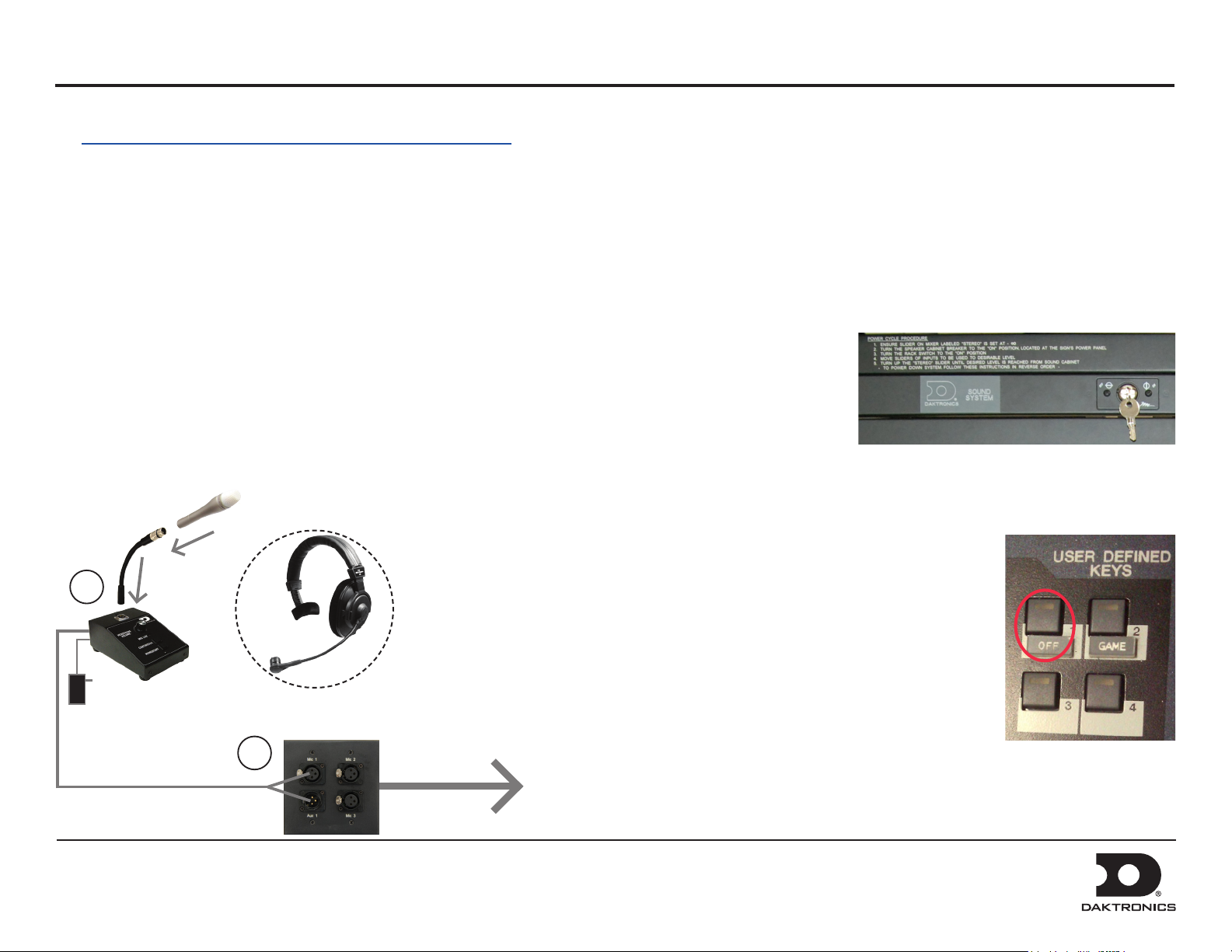
Setup
The announcer’s interface equipment is typically kept in the bottom
storage drawers along with other accessories. Follow the steps below to
properly reconnect it to the rack.
1. Connect one end of the XLR gooseneck to the wired microphone
and the other end into the jack on top of the announcer’s interface.
Also plug the wallpack transformer into a standard power outlet.
Note: The headset microphone may be connected to the announcer’s
interface via the XLR jack and the HEADPHONES jack (on rear).
2. Connect the 15' (4.6 m) XLR cable (part # W-2074) from MIC 1 &
AUX 1 on the announcer’s interface to Mic 1 & Aux 1 on the
announcer’s plate.
1
27 RU Rack Only
For the 27 RU rack, there will be a 25' (7.6 m) or 50' (15.2 m) cable harness factory
wired to the rack. Route this cable to the desired mixer location and connect each
plug to the appropriate jack on the mixer according to the wire labels. Plug the mixer
into a standard power outlet.
Powering On
Unlock the door of the rack, and turn
the SOUND SYSTEM key switch to
the ON (vertical) position.
Note: Keep both sets of keys in a safe
location to prevent tampering/theft
of rack equipment!
Powering Down
1. Press the USER DEFINED KEY on mixer labeled OFF.
2. Turn the SOUND SYSTEM key switch to the OFF
(horizontal) position.
3. If the system will not be used for some time, unplug
the power cord.
Announcer’s
Interface
DD2222144 Rev 2
05 March 2014
2
Announcer’s
Plate
4. Place all accessories back in the appropriate slots of the
storage drawers to keep them safe and organized.
5. Close and lock the rack door.
To Rack
201 Daktronics Drive PO Box 5128, Brookings, SD 57006-5128
Tel: 1-800-DAKTRONICS (1-800-325-8766) Fax: 605-697-4746
Web: www.daktronics.com/support
Page 2
Sportsound SSR-300 Quick Start Guide 2 of 6
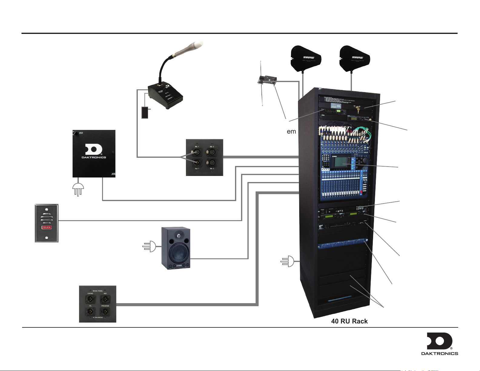
This page shows the most common
components and accessories for the
40 RU SSR-300 rack. Locations of
equipment will vary by facility.
Fiber Box
Announcer’s
Interface
Announcer’s
Plate
Hearing
Assist System
High Gain
Antennas
Sound System
ON/OFF Control
Personal
Monitor
System Receiver
Pro Mixer
(remotely located
with 27 RU Rack)
CD Player
Wireless Mic
Receiver
Crowd
Mic
(home/guest
radio, press,
truck dock)
DD2222144 Rev 2
05 March 2014
Media
Distribution
Plates
(up to 4)
Self-Powered
Monitor
(@ 1 or 2)
201 Daktronics Drive PO Box 5128, Brookings, SD 57006-5128
Tel: 1-800-DAKTRONICS (1-800-325-8766) Fax: 605-697-4746
Web: www.daktronics.com/support
40 RU Rack
Feedback
Reducer
Distribution
Amplier
Storage
Drawers
Page 3

Sportsound SSR-300 Quick Start Guide 3 of 6
Audio Mixer Operation
With the SOUND SYSTEM key switch in the ON position:
Press the USER
1. 2.
DEFINED KEY
labeled GAME.
Custom keys may
have been set up
during training.
Press the desired
key as needed for a
specic application.
Ensure the ON buttons
4.
for the channels in use
and for the STEREO
slider are illuminated.
Also verify no SOLO
buttons are illuminated.
5.
Bring sliders up
slowly and listen
for your signal.
Ensure all source equipment is
turned on and operational (refer to
the appropriate pages of this guide).
The signal should be visible on the STEREO output meter:
6.
• The amber LEDs indicate that the level is near clip.
• The red LEDs indicate that the signal has reached the digital limit.
REMEMBER: Bad input = bad output.
No adjustment on the mixer can make
a poor source sound better. For best
results, be sure to use high-quality audio
les from your MP3 player or laptop,
and set the device to near full volume.
Verify gain knobs for the
3.
channels in use are adjusted
so the SIGNAL light is green
and the PEAK light is not lit.
DD2222144 Rev 2
05 March 2014
201 Daktronics Drive PO Box 5128, Brookings, SD 57006-5128
Tel: 1-800-DAKTRONICS (1-800-325-8766) Fax: 605-697-4746
Web: www.daktronics.com/support
Page 4

Sportsound SSR-300 Quick Start Guide 4 of 6
Wireless Receiver System Operation
a b
e fd
1. Ensure all transmitters are powered off. Flip the power on/off
switch to turn on one receiver if it is not already on.
The unit can display the following information:
a) Group Number
b) Channel Number
c) Transmitter Battery Life
2. Hold the SET button and then press MODE once. The word SCAN
will appear on the display. To begin scanning, simply rotate the
control knob. When all groups have been scanned, the group with
the most open channels will appear. Press SET to accept the
recommended GROUP and assign the clearest CHANNEL.
c
Control
Knob
d) RF Signal Strength
e) Transmitted Audio Signal Strength
f) Frequency
Power
ON/OFF
Wireless Microphone & Bodypack Operation
Power
ON/OFF
Control
Buttons
Power
ON/OFF
1. Open the battery cover. Insert new or fully-charged 9V batteries prior to each
use, and always have spares on hand.
2. Power on the device. Note that with the handheld mic, you must remove the
protective sleeve to access the power and control buttons.
3. Hold MODE until only the GROUP number is visible. Use SET to select
the same group number as the rst receiver unit. Press MODE to continue.
Use SET to select the same CHANNEL number as the rst receiver unit and
then press MODE to save the settings.
3. Turn on the second receiver unit. Press MODE twice and use the
control knob to select the same GROUP as the rst receiver.
Press SET and select a different CHANNEL than the rst receiver.
The next highest number should work, but it may be necessary
to select another. Press SET again to save the settings.
Note: Perform a scan on all of the wireless units just minutes before
the game! If a scan is performed too far ahead of time, frequencies set
up by the media later on may interfere with previously congured
wireless microphone settings.
DD2222144 Rev 2
05 March 2014
201 Daktronics Drive PO Box 5128, Brookings, SD 57006-5128
Tel: 1-800-DAKTRONICS (1-800-325-8766) Fax: 605-697-4746
Web: www.daktronics.com/support
4. Repeat steps 1-3 with the second transmitting device, using the GROUP and
CHANNEL settings of the second receiver unit.
Note: Plug the mic switch into the jack on top of the bodypack unit and plug
headphones/lapel mic into the mic switch.
Verify Reception: With a transmitter and the receiver both turned on and
having matching GROUP and CHANNEL numbers, the RF meter on the receiver
should be indicating signal. Speak into the microphone and the TX AUDIO meter
should indicate signal presence.
Page 5

Sportsound SSR-300 Quick Start Guide 5 of 6
Personal Monitor System Operation
3
1
2
5 6
1. Flip the transmitter POWER switch to ON if it is not already on; ensure the RF
switch to the left of it is OFF at this time.
2. Power on the handheld receiver using the volume knob.
3. Attach the antenna and earphones to the top of the handheld receiver.
4
4. Flip open the battery cover to expose the control buttons. Press SCAN and the
display will show “SYNC NOW”.
Note: Insert new or fully-charged batteries prior to each use, and always
have spares on hand.
4. Hold the bodypack up to the transmitter with the sync IR windows facing
each other, and press the SYNC button on the transmitter. The display will
show “SYNC SUCCESS” when nished.
5. Flip the transmitter RF switch to ON. The blue LED on the receiver should
illuminate to indicate that it is detecting the transmitter.
DD2222144 Rev 2
05 March 2014
201 Daktronics Drive PO Box 5128, Brookings, SD 57006-5128
Tel: 1-800-DAKTRONICS (1-800-325-8766) Fax: 605-697-4746
Web: www.daktronics.com/support
Page 6

Sportsound SSR-300 Quick Start Guide 6 of 6
Hearing Assist System Operation
1
1. Press POWER to turn on the transmitter if it is not already on.
2. Use the CHANNEL SELECT buttons to select a channel.
3. Plug the earphones into the jack on top of the handheld receiver.
4. Rotate the volume dial counterclockwise to power on the handheld receiver.
5. Flip open the battery cover to expose the control buttons. Use the CHANNEL
SELECT buttons to select the same channel that was set on the transmitter,
or press SEEK to locate the active channel.
Note: Insert new or fully-charged batteries prior to each use, and always
have spares on hand.
2
3
4
5
6. Repeat steps 3-5 for any additional receivers.
DD2222144 Rev 2
05 March 2014
201 Daktronics Drive PO Box 5128, Brookings, SD 57006-5128
Tel: 1-800-DAKTRONICS (1-800-325-8766) Fax: 605-697-4746
Web: www.daktronics.com/support
 Loading...