

Page 1
S SERIES OPERATION & MAINTENANCE MANUAL
Page 2

Page 3

S SERIES OPERATIONS MANUAL
Daktronics Automated Rigging System
Manufacturer’s contact info
7200 Rawson Road
Victor, New York 14564
tel 866-486-7835 585-924-5000
fax 585-924-0545
email sales@daktronics.com
web site www.daktronics.com/rigging
Page 4

TABLE OF CONTENTS
01 Theory of Operation ................................................................................ 01
Vortek S-Series Controller
Movements of the hoist
Power supply
02 Batten and Hoist Loading Information .........................................................02
Uniformly distribute loads
Understanding stage rigging
03 Motorized Batten Hoists ............................................................................ 02
Hoist unit composition
Patented load brake
VSC and the hand-held pendant controller
04 Daktronics S Series Controller .....................................................................04
Description
Operation
Recommended procedures
05 Troubleshooting Guide......................................................................................06
Symptoms
Causes
Corrective strategies
06 Maintenance Guide...........................................................................................07
07 Warranty ................................................................................................ 17
One year warranty
Responsibilities under warranty
Compliance with warranty
i
TABLE OF CONTENTS
Page 5
01 THEORY OF OPERATION
Each Vortek hoist is connected to the main high voltage power buss through a safety twistlocking plug. This plug brings in the main 208 or 480 VAC (refer to system riser), 3-phase
power that is connected to the motor contactors and motor brake located in each hoist
assembly. The high voltage power originates in the Master Control Cabinet (MCC). Also
connected to each Vortek hoist assembly through a safety locking connector are 24-volt DC
control and E-Stop circuit.
The reversing contactors control all movements of the hoist. Each S Series controlled
hoist with Push Button Control runs in open loop and is controlled at the main MCC via
momentary push buttons. Each hoist is protected via hardwired UP and DOWN control
signals, hard struck limit switches, emergency stop status and optional over/under capacity
sensors. The UP and DOWN control signals determine which contactor to energize for
direction to run the hoist (Figure 1). The limit switches are used for maximum up and
down travel. The emergency STOP status is used to detect the operation of the emergency
stop system and the
optional over/under
capacity sensors will
ensure that the hoist is
being operated within its
designed capacity.
Housed within the MCC
is a 24-volt DC power
supply that powers the
control circuit and the
E-Stop circuit. A fused
disconnect and a master
control contactor are also
mounted inside the MCC.
The 24-volt DC E-Stop
circuit is connected to the
E-STOP button located
on the front of the master
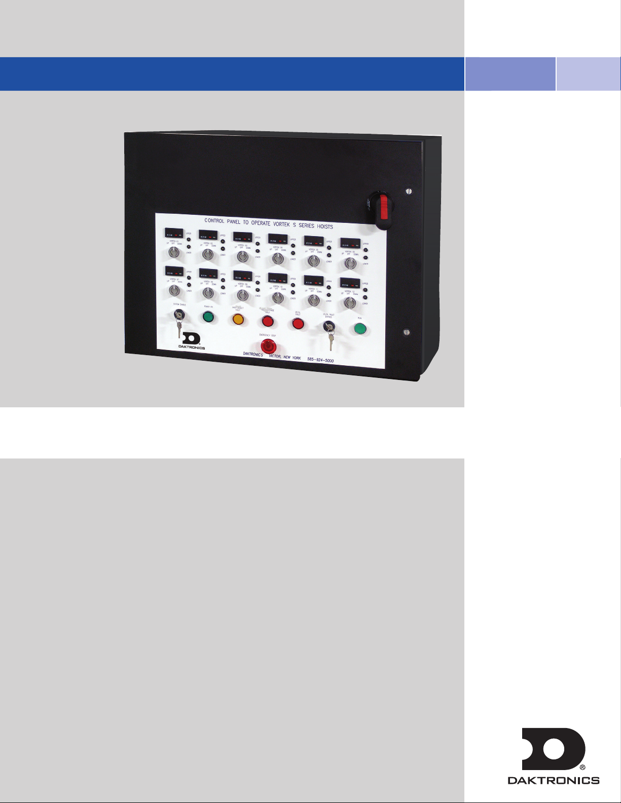
FIGURE 1: S Series Control panel
applicable.
control cabinet as well as
the E-STOP button located
on the pendant, if
THEORY OF OPERATION
1
Page 6

02 BATTEN AND HOIST LOADING INFO
Uniformly distribute loads.
Ensure loads are applied to 2 or more lift lines.
• Max. 1500 Pounds Total Applied Load Per Winch
• Maximum live load design capacity on each batten = 30 Pounds Per Linear Foot
• Do Not Concentrate Full-Capacity Point Loads on One Lift Line
Daktronics strongly recommend a thorough understanding of stage rigging practices
before any changes are made to batten loads. Many reference sources are available
that contain important information that will allow you to safely hang heavy loads
once you understand the limitations and dynamics of the materials used in rigging:
wire rope, pipe battens, etc.
03 MOTORIZED BATTEN HOISTS
The Vortek hoist system is a dead-haul system meaning that the load is not counterweighted. Each hoist can lift loads only up to the design capacity. Overloading
will result in electrical overload protection shut down of the hoist and possible
damage to rigging components.
Each hoist unit consists of an integral electric motor driven reducer, directly
coupled to a cable drum, which winds steel cables (wire ropes) leading over
sheaves installed within the hoist assembly and along the structural steel of the
building. The cables support battens for attaching the load. The battens can
be lowered to the lower hard struck limit to allow attachment of loads. Refer to
installation drawings for the exact location and dimensions.
Warning:
The VORTEK Batten Hoists are not designed to raise and
lower people. These hoists should NEVER be used for
this purpose.
2
Page 7

The Vortek S Series Hoist System consists of three basic parts:
1. The S Series controller - where the operator controls the system.
2. The Vortek hoist wireways - connect the controls to the
hoists themselves.
3. The Vortek hoist units - completely self-contained electrical and
mechanical equipment.
1. The hoist power panel assembly is located at the end of each Vortek motorized
hoist (the blue box at the end where the HV and LV cables plug in). There is a
resettable circuit breaker located at each power outlet on the High Voltage
wireway that also serves as a safety disconnect. The rated twist-locking plug on
each unit also acts as a main (local) high voltage disconnect.
2.
The Vortek hoist units are mounted on structural steel, usually at the top of the
stage house (refer to your project installation drawings for exact placement of the
hoist units). The gear motor, helically grooved cable drum, support bearing and
frame structure are all factory assembled and tested. On each hoist assembly
is one set of hard struck limit switches. These limits are the upper ultimate limit
and lower ultimate limit. These limit switches are adjusted by factory-trained
personnel at the factory test and are fine tuned on site by the installer during
installation and commissioning of the system. There is also one set of over travel
limits. Each hoist assembly is also equipped with our PATENTED LOAD BRAKE,
a unique safety feature provided exclusively by Daktronics. This brake is a
fully-mechanical, always engaged drive-through secondary brake. This greatly
reduces any possibility of a loaded batten to descend uncontrolled.
3. Control of all hoists is possible from the S Series controller or hand-held
pendant controller, located such that a clear line of site can be achieved.
4. The controller contains the main system disconnect, master control contactor,
control voltage power supply and control buttons.
5. Please see the Controls Operating portion of this manual for the operating
procedures.
Warning:
If it is necessary to operate a hoist from a location
where the operator’s view of the moving load is
obstructed, a second person must be used to observe
the load and communicate to the operator.
MOTORIZED BATTEN HOISTS
3
Page 8

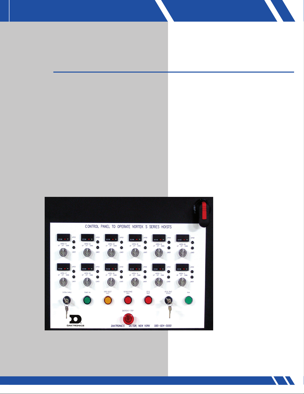
04 S SERIES CONTROLLER
Description:
The Daktronics S Series Controller is the most economical form of control available and should be
selected only if precise positioning and speed control is not required. The MCC will contain an “UP/
OFF/DOWN” switch for each Vortek hoist on the system, a main “Power On” key switch, one master
“RUN” button, an “Emergency Stop” button located on the bottom of the MCC, and indicator lights
for “POWER ON”, “OVERTRAVEL FAULT”, “OVERSELECT FAULT”, and “VOLTAGE/PHASE FAULT”.
A lockable main power disconnect handle will also be accessible on the front of the MCC for the
removal of all power from the system. The optional handheld pendant controller will contain “RUN”
and a locking “Emergency Stop” buttons along with indicator lights for “ACTIVE” and “Emergency
Stop”. The handheld pendant should be used where proper Line-of-Site is not feasible from the
location of the MCC.
Operation:
To power up the system:
Turn on the main disconnect switch located on the front of the master control cabinet and then turn
the key switch on. The green power light should now be illuminated. If the green power light does
not illuminate, check to make sure that the E-Stop button are not pressed.
If the red light stays illuminated, then one of the over travel limits has been engaged. Contact
Daktronics for instructions on resolving this issue.
4
Page 9

Hoist operation:
The MCC is the single point of operation for the Vortek S Series System.
There is one master RUN button located on the MCC along with an UP/OFF/DOWN selector switch
for each hoist in the system. There is an E-STOP button located at the bottom of the MCC as well.
To raise a hoist, turn the selector switch for the
desired hoist to the UP position (Figure 2) and
press RUN. The hoist will run at full speed in the
up direction. The hoist will run until the button is
released and/or the hoist reaches its upper hardstruck limit switch. When the move is completed,
return the selector switch back to OFF.
To lower a hoist, turn the UP/OFF/DOWN selector
switch for the desired hoist to the down position
and press RUN. The hoist will run at full speed. The
hoist will run until the button is released or the hoist
FIGURE 2: Selector switches
Up to 4 hoists can be run at one time using multiple selector switches. The hoists will run in the direction
selected, meaning that some could be running up and others down.
The position displays show the height above the floor for each batten (Figure 3). This is set during
initial installation and should not need to be changed.
reaches its lower hard-struck limit switch.
However, with these displays, whenever the red button is pushed, it re-sets the display to a pre-set
number which is 4.00 ft even if the batten is above or
below 4.00 ft.
To set the display so that the batten height above floor is correct, lower (or raise)
the batten to 4 ft (have someone measure with a tape measure to the BOTTOM
of the batten) and then push the red button on the display.
FIGURE 3: Position display
Warning:
If any problems arise during any hoist motions, depress
any of the EMERGENCY STOP buttons.
HOIST OPERATION
5
Page 10

Description and Operation of Indicator Lights
POWER ON: Indicates that Main Disconnect is turned on and the “System Enable” key switch is also
enabled.
OVERTRAVEL FAULT: Indicates that any one of the hoists has traveled too far and is causing a ‘Ground
Out’ condition. In the unlikely event when this light is illuminated, NO hoist will operate. Please call
Daktronics for help on resolving this issue.
OVER SELECT FAULT: Lights up when more than 4 hoists are selected to run at one time and will prevent any hoists from operating. Deselecting hoists will turn this indicator off and enable the hoists to
operate once more.
VOLTAGE/PHASE FAULT: Lights up when voltage is Under or Over by 10% of specified settings. (Set to
specified voltage per installation, either 208v or 480v). This light also lights up when phase reversal is
detected and will prevent the system from operating.
05 TROUBLESHOOTING GUIDE
Symptom
Green power light is NOT ON
Overtravel light is ON
Overtravel light is FLASHING
Vortek hoist will not move
when commanded
Possible Cause Corrective Action
Main power turned OFF
E-Stop button pressed
Key switch turned OFF
Over travel limit reached
Over/Under capacity (if load
sensing option is included)
Main power turned OFF
E-Stop button pressed
Motor overload
Hoist has reached limit switch
Circuit breaker tripped on
wireway
Too many hoists selected
Turn on Main Disconnect
Release E-Stop button
Turn key switch ON
Check over travel limits
Confirm that load is within
the capacity of the hoist
Turn main disconnect ON
Check all E-Stop buttons
Wait for automatic reset
Move hoist in opposite
direction of travel
Press red reset button at hoist end
(power panel assembly)
Reduce the number of hoists
selected
For service contact:
Daktronics
7200 Rawson Road
Victor, New York 14564
6
Telephone: 585-924-5000
Fax: 585-924-0545
www.daktronics.com/rigging email sales@daktronics.com
Page 11

06 MAINTENANCE
In order to maintain a safe and efficient hoist system, it is necessary to implement a regular and continual
preventative maintenance program. Listed below are the critical areas of the hoist system that need consistent review, inspection, and/or correction. This list is a guideline to assist in establishing a maintenance
program, but cannot replace ongoing visual inspection by operating personnel. Daktronics should be
contacted immediately if any irregularities are found.
To prevent accidents, injuries, or failures Daktronics recommends a professional inspection at least once
each year. Daktronics offers the most thorough preventative maintenance program in the motorized rigging
industry. This program will be offered to facility management after your hoist installation is complete.
The system should be run for a minimum of 2 minutes every month in order to ensure
proper lubrication. Neglect may result in damage to the rigging system.
Periodic inspections when operating the hoist should include the following:
SWAGED CONNECTORS Look for wire rope damage where the swaged connector contacts the cable.
Check for broken cable strands.
TURNBUCKLES: Check that cotterpins and pin nuts, or bolts and nuts are in place and secure.
Check that pins in jaws are not bent. If bent pins are found, the set has been
over-loaded and should be inspected professionally for more serious damage.
WIRE ROPE: Check for worn areas, kinks, broken wire strands, or any deformation.
Examine cable runs for any obstructions or sources of abrasion. Excessive
dirt will shorten the life of the cable. If cable has begun to rust it must be
replaced immediately.
REDUCERS: Check for visible oil leaks. If any noticeable oil leaks occur, please call
Daktronics immediately.
BRAKEMOTORS: Listen for unusual noises such as squeaking or grinding which may indicate
the need for lubrication or brake adjustments. Call a Vortek service
representative for any brakemotor service (585) 924-5000.
ELECTRICAL: Check to ensure that electrical flex connections are secure and that no wires
or connections have been pulled apart. WITH ALL POWER OFF, open starter
cabinets and verify that wires are clean and orderly. Check that all cabinet
doors are properly secured prior to energizing.
HOIST ASSEMBLY: Check that all cables are smoothly wrapped on drum. Cables should not climb
over adjacent wraps. If excessive dirt is accumulating on drum, steps must be
taken to remove and prevent this accumulation.
MAINTENANCE
7
Page 12

The Vortek hoist is designed for years of trouble-free service and maintenance servicing is enhanced by the
design. The components used in the Vortek hoist are industrial and engineered for 24/7 usage (hoists rated 25%
duty cycle) and require very little maintenance aside from some biannual lubrication.
SUPPLIES NEEDED
All supplies are available at most hardware stores.
White Lithium Grease for the
Acme screw (spray or hand applied)
3-in-1 oil for the drum shaft
Blue shop towels for cleaning and applying oil
Air duster for blowing out control panel (if required)
8
Page 13

MAINTENANCE PROCESS
• Access to the onstage portion of the hoist is important when doing part of the maintenance work
and also on the offstage side at the electrical cabinet.
• Remove the two 7/32" Allen head screws that are at
the onstage end of the hoist.
This is a cover for both the Drum Shaft and the
Acme Screw. The cover does not have to be
completely removed, instead pull it down
out of the channels.
• The pictures below show the end view of the Drum
Shaft and Acme Screw (albeit without covers on).
• Take a Blue Shop towel or clean
towel spread a small amount of
the 3-in1 oil onto the towel and
wipe it on/over the Drum Shaft.
Use this first towel to clean the shaft
of dust and grit. Use a 2nd towel
that is liberally anointed with the
3-in-1 oil to lubricate the shaft,
making sure to wipe all
around the shaft.
• Always use a clean towel when doing the first wipe down on the
Drum shaft to avoid spreading the grime from unit to unit.
• When lubricating the Acme Screw be sure to have as much of the screw showing as possible.
To achieve this, raise the batten to its highest point of travel. Take another Blue Shop Towel
as a backing towel to prevent overspray and spray the Acme Screw with White Lithium
lubricant. Just one quick pass usually suffices for lubricating this screw.
• Upon completing the lubrication, replace the cover making sure to fit the cover into the
channels on the aluminum backbone.
MAINTENANCE
9
Page 14

• The final step is blowing out the dust from the electrical enclosure with the compressed air.
• Turning off power at the circuit breaker and unplugging the communications plug from the top
of the Vortek hoist will make it safe to open up the enclosure.
• Using the same 7/32” hex key, remove the
2 Allen head screws from the top of the
electrical enclosure and swing down
the cover.
• Hint: pushing the cover up at the curved
hinges while swinging the cover down will
help in opening the enclosure.
• Using a low to medium pressure air stream,
gently blow any dirt and dust bunnies from
the ventilation holes from both sides of the
drive inverter.
Note: Safety glasses should be worn during this
procedure.
• Re-install the cover to complete this maintenance portion of the Vortek hoist.
• Last thing to check is the attachment connections for the hoist to the
structural steel.
Check these two 9/16” hex
head bolts for torque
values of 17-20ft/lbs.
Check both sets of clamps.
Check the nuts on the backbone stiffeners for tightness.
10
Page 15

LOFT BLOCK MAINTENANCE
3/4” Hex Nut
Axle “Circlip” (check both sides)
The Vortek Loft Block has sealed bearings and usually needs minimal maintenance but the mounting
hardware should be checked and a few other simple inspections will suffice.
1. Check for proper torque on the beam clamp bolt and nut. This should be
17-20 ft/lb of torque using a torque wrench to confirm.
2. There are ‘Circlips’ on both sides of the 2 axles on the loft block. Check to make
certain that the clips are seated in the groove on the axle.
3. Look to see that all of the plastic covers are snapped into place.
4. The loft block should be free to swing in both a side to side motion and up/down
to a small extent.
TURNBUCKLE MAINTENANCE
Turnbuckle maintenance requires checking the locknuts to make
sure they are tight to prevent the turnbuckle from loosening or, if
your turnbuckles do not have locknuts then make sure that they
are moused.
Also check to assure that the cable drops are plumb and
not angled. The hanger bracket that is attached to the A-14
Aluminum Batten and the turnbuckle also should not be bent.
MAINTENANCE
11
Page 16

VORTEK HOIST BRAKE ADJUSTMENTS
Occasionally the secondary mechanical brake may need some minor adjustment to alleviate noise that
could occur.
Remove the Locknut from here, and allow cover to swing down.
The motor cover will need to be opened up so that the brake can be adjusted.
What will be seen is shown in the picture below.
The locknut on the secondary
mechanical brake is what will
be adjusted.
Bronze Bearing
Belleville Washer
To adjust the brake, loosen the locknut on the gearbox shaft until the Bronze Bearing and the
Belleville Washer spin with a small amount of finger pressure.
12
Page 17

Run the hoist DOWN approximately two feet so that the secondary brake is engaged and then tighten
the locknut to 70 Inch/pounds with a Torque wrench. Run the hoist down and check for noise.
If there is still noise, tighten the nut 1/8 of a turn and then run the hoist down again. Repeat until
the noise has ceased.
Do not tighten the nut to where there is no more adjustment available.
CHECKING BRAKE PAD WEAR
The brake pads should be checked for wear on a routine basis. The pads may wear unevenly so
both sides need to be checked. Measure the distance between the brake disc and the ratchet wheel
(both sides). The distance (space) should be greater than .065”. If .065” or less the brake pads need
replacement at the factory.
BRAKE PAD THICKNESS
MEASURE HERE (2 PLACES)
IF .065” OR LESS REPLACE PADS
Ratchet WheelBrake Disc
After making the adjustment and checking the Brake Pads, re-install the cover making sure to fit the
cover into the slots on the backbone.
MAINTENANCE
13
Page 18

14
Page 19

MAINTENANCE
15
Page 20

16
Page 21

07 WARRANTY
The Daktronics Standard Warranty (the “Warranty”) sets forth the warranty provided by Daktronics with respect to the Equipment.
By accepting delivery of the Equipment, Purchaser agrees to be bound by and accept these terms and conditions. All defined terms
within the Warranty shall have the same meaning and definition as provided elsewhere in the Agreement.
DAKTRONICS WILL ONLY BE OBLIGATED TO HONOR THE WARRANTY SET FORTH IN THESE TERMS AND CONDITIONS UPON
RECEIPT OF FULL PAYMENT FOR THE EQUIPMENT.
1. Warranty Coverage
A. Daktronics warrants to the Purchaser that the Equipment will be free from Defects (as defined below) in materials and
Workmanship. Warranty period shall be for 15 months after date of shipment – parts and labor.
B. Daktronics’ obligation under this Warranty is limited to, at Daktronics’ option, replacing or repairing, any Equipment or part
that does not conform to the Equipment specifications. Unless otherwise directed by Daktronics, any defective part or component
shall be returned to Daktronics for repair or replacement. Daktronics may, at its option, provide on-site warranty service. Daktronics
shall have a reasonable period of time to make such replacements or repairs and all labor associated therewith shall be performed
during regular working hours. Regular working hours are Monday through Friday between 8:00 a.m. and 5:00 p.m. at the
location where labor is performed, excluding any holidays observed by either Purchaser or Daktronics.
C. Daktronics shall pay ground transportation charges for the return of any defective component of the Equipment. If returned
Equipment is repaired or replaced under the terms of this warranty, Daktronics will prepay ground transportation charges back to
Purchaser; otherwise, Purchaser shall pay transportation charges to return the Equipment back to the Purchaser. All returns must be
pre-approved by Daktronics before shipment. Daktronics shall not be obligated to pay freight for any unapproved return. Purchaser
shall pay any upgraded or expedited transportation charges.
D. Any replacement parts or Equipment will be new or serviceably used, comparable in function and performance to the original
part or Equipment, and warranted for the remainder of the Warranty Period. Purchasing additional parts or Equipment from the
Seller does not extend this Warranty Period.
E. Defects shall be defined as follows. A “Defect” shall refer to a material variance from the design specifications that prohibit the
Equipment from operating for its intended use. The Warranty does not provide for the replacement or installation of communication
methods including but not limited to, wire, fiber optic cable, conduit, trenching, or for the purpose of overcoming local site
interference radio equipment substitutions.
THIS LIMITED WARRANTY IS THE ONLY WARRANTY APPLICABLE TO THE EQUIPMENT AND REPLACES ALL OTHER WARRANTIES
OR CONDITIONS, EXPRESS OR IMPLIED, INCLUDING, BUT NOT LIMITED TO, THE IMPLIED WARRANTIES OR CONDITIONS
OF MERCHANTABILITY AND FITNESS FOR A PARTICULAR PURPOSE. SPECIFICALLY, EXCEPT AS PROVIDED HEREIN, THE SELLER
UNDERTAKES NO RESPONSIBILITY FOR THE QUALITY OF THE EQUIPMENT OR THAT THE EQUIPMENT WILL BE FIT FOR ANY
PARTICULAR PURPOSE FOR WHICH PURCHASER MAY BE BUYING THE EQUIPMENT. ANY IMPLIED WARRANTY IS LIMITED IN
DURATION TO THE WARRANTY PERIOD. NO ORAL OR WRITTEN INFORMATION, OR ADVICE GIVEN BY THE COMPANY, ITS
AGENTS OR EMPLOYEES, SHALL CREATE A WARRANTY OR IN ANY WAY INCREASE THE SCOPE OF THIS LIMITED WARRANTY.
WARRANTY
17
Page 22

2. Exclusion from Warranty Coverage
The Warranty does not impose any duty or liability upon Daktronics for:
A. Any damage occurring, at any time, during shipment of Equipment unless otherwise provided for in the
Agreement. When returning Equipment to Daktronics for repair or replacement, Purchaser assumes all risk of loss or
damage, and agrees to use any shipping containers that might be provided by Daktronics and to ship the Equipment
in the manner prescribed by Daktronics;
B. Any damage caused by the unauthorized adjustment, repair or service of the Equipment by anyone other than
personnel of Daktronics or its authorized repair agents;
C. Damage caused by the failure to provide a continuously suitable environment, including, but not limited to: (i)
neglect or misuse, (ii) a failure or sudden surge of electrical power, (iii) improper air conditioning or humidity control,
or (iv) any other cause other than ordinary use;
D. Damage caused by fire, flood, earthquake, water, wind, lightning or other natural disaster, strike, inability to
obtain materials or utilities, war, terrorism, civil disturbance or any other cause beyond Daktronics’ reasonable
control;
E. Failure to adjust, repair or replace any item of Equipment if it would be impractical for Daktronics personnel to
do so because of connection of the Equipment by mechanical or electrical means to another device not supplied
by Daktronics, or the existence of general environmental conditions at the site that pose a danger to Daktronics
personnel;
F. Any statements made about the product by salesmen, dealers, distributors or agents, unless such statements are in
a written document signed by an officer of Daktronics. Such statements as are not included in a signed writing do not
constitute warranties, shall not be relied upon by Purchaser and are not part of the contract of sale;
G. Any damage arising from the use of Daktronics products in any application other than the commercial and
industrial applications for which they are intended, unless, upon request, such use is specifically approved in writing
by Daktronics; or
H. Any performance of preventive maintenance.
18
3. Limitation of Liability
Daktronics shall be under no obligation to furnish continued service under this Warranty if alterations are made to the
Equipment without the prior written approval of Daktronics.
The use of any non-Daktronics controller or software shall void the Warranty.
It is specifically agreed that the price of the Equipment is based upon the following limitation of liability. In no event
shall Daktronics (including its subsidiaries, affiliates, officers, directors, employees, or agents) be liable for any
special, consequential, incidental or exemplary damages arising out of or in any way connected with the Equipment
or otherwise, including but not limited to damages for lost profits, cost of substitute or replacement equipment, down
time, lost data, injury to property or any damages or sums paid by Purchaser to third parties, even if Daktronics has
been advised of the possibility of such damages. The foregoing limitation of liability shall apply whether any claim is
based upon principles of contract, tort or statutory duty, principles of indemnity or contribution, or otherwise.
In no event shall Daktronics be liable to Purchaser or any other party for loss, damage, or injury of any kind or nature
arising out of or in connection with this Warranty in excess of the purchase price of the Equipment actually delivered
to and paid for by the Purchaser. The Purchaser’s remedy in any dispute under this Warranty shall be ultimately
limited to the Purchase Price of the Equipment to the extent the Purchase Price has been paid.
Page 23

4. Dispute Resolution
Any dispute between the parties will be resolved exclusively and finally by arbitration administered in accordance with the rules
of the American Arbitration Association (“AAA”), except as otherwise provided below. The arbitration will be conducted before
a single arbitrator. The arbitration shall be held in Rochester, New York. Any decision rendered in such arbitration proceedings
will be final and binding on each of the parties, and judgment may be entered thereon in any court of competent jurisdiction.
This arbitration agreement is made pursuant to a transaction involving interstate commerce, and shall be governed by the Federal
Arbitration Act.
5. Governing Law
The rights and obligations of the parties under this warranty shall not be governed by the provisions of the United Nations
Convention on Contracts for the International Sales of Goods of 1980. Both parties consent to the application of the laws of the
State of New York to govern, interpret, and enforce all of Purchaser and Daktronics rights, duties, and obligations arising from, or
relating in any manner to, the subject matter of this Warranty, without regard to conflict of law principles.
6. Availability of Service Agreement
For Purchaser’s protection, in addition to that afforded by the Warranty, Purchaser may purchase extended services to cover the
Equipment. A Service Agreement is available from Daktronics and may provide for electronic parts repair and/or on-site labor
for an extended period from the date of expiration of this Warranty. Alternatively, a Service Agreement may be purchased in
conjunction with this Warranty for extended additional services. For further information, contact Daktronics Customer Service at
1-800.325.8766.
WARRANTY
19
Page 24

Page 25

Daktronics
7200 Rawson Road Victor, New York 14564 USA
tel 866-486-7835 585-924-5000 fax 585-924-0545
www.daktronics.com/rigging email sales@daktronics.com
Copyright © 2013 Daktronics, Inc. DD1969094 REV3 17 July 2013
 Loading...