

Page 1

Display Manual
DataTrac
S-100 and S-200
0.7”, 1.2” and 2.1”
ED-10191
DataTrac is a trademark and Venus is a registered trademark of Daktronics, Inc.
All other trademarks are the property of their respective owners.
ED-10191
Product 1120
Rev 6 – 10 March 2002
Copyright 2001 Daktronics, Inc.
All rights reserved. While every precaution has been taken in the
preparation of this manual, the publisher assumes no responsibility for errors
or omissions. No part of this book covered by the copyrights hereon may be
reproduced or copied in any form or by any means – graphic, electronic, or
mechanical, including photocopying, taping, or information storage and retrieval
systems – without written permission of the publisher.
331 32nd Ave PO Box 5128 Brookings SD 57006
Tel 605-697-4036 or 877-605-1115 Fax 605-697-4444
www.daktronics.com e-mail: helpdesk@daktronics.com
Page 2

Page 3

Table of Contents
Section 1: Introduction....................................................................................................1-1
1.1 How to Use this Manual ..................................................................................... 1-1
1.2 Safety Precautions .............................................................................................. 1-4
1.3 Network Concepts..............................................................................................1-4
RS232 Network..................................................................................................1-4
RS422 Network..................................................................................................1-5
Modem Network................................................................................................1-5
TCP/IP Network................................................................................................1-5
1.4 Display Overview ............................................................................................... 1-5
1.5 Definitions..........................................................................................................1-7
1.6 Daktronics Nomenclature....................................................................................1-8
Section 2: Mechanical Installation.................................................................................2-1
2.1 Support Structure Design ....................................................................................2-1
2.2 Display Ventilation Requirements ........................................................................2-1
2.3 Display Mounting................................................................................................2-2
Hanging Mount...................................................................................................2-2
Wall Mount........................................................................................................2-2
Section 3: Electrical Installation.....................................................................................3-1
3.1 Common Connectors ..........................................................................................3-1
3.2 Signal.................................................................................................................3-2
Cables ...............................................................................................................3-2
Installing an RJ Connector ................................................................................... 3-2
Pin-Outs ............................................................................................................3-4
3.3 Power................................................................................................................3-4
Power Requirements ..........................................................................................3-4
Grounding ..........................................................................................................3-4
Power Connection B Pluggable Cord Connected Displays .....................................3-4
3.4 Computer to Sign ................................................................................................ 3-5
RS232 System....................................................................................................3-5
RS422 System....................................................................................................3-5
Modem System..................................................................................................3-7
TCP/IP or LAN System.....................................................................................3-7
3.5 Sign to Sign Connections .....................................................................................3-7
Section 4: Maintenance & Troubleshooting................................................................4-1
4.1 Opening the Display............................................................................................4-1
4.2 Accessing the Interior of the Display...................................................................4-2
4.3 Display Interior ................................................................................................... 4-3
LED Module Replacement .................................................................................. 4-3
Table of Contents
i
Page 4

Power Supply Replacement.................................................................................4-4
0.7" Displays ..........................................................................................4-4
1.2" & 2.1" Displays ...............................................................................4-5
Both 0.7” and 1.2/2.1” Displays ............................................................... 4-5
Display Controller ............................................................................................... 4-6
Modem..............................................................................................................4-6
Fans (0.7" Display, 8 & 12 Lines Only) ................................................................4-7
Light Detector....................................................................................................4-7
Fuse ..................................................................................................................4-8
4.4 Controller Address and Test Mode ......................................................................4-8
4.5 Troubleshooting..................................................................................................4-9
4.6 Replacement Parts ........................................................................................... 4-10
Common Parts (All Models) .............................................................................. 4-10
0.7" Display...................................................................................................... 4-10
1.2" Display...................................................................................................... 4-10
2.1" Display...................................................................................................... 4-11
4.7 Daktronics Exchange/Repair & Return Programs............................................... 4-11
Appendix A: Optional Temperature Sensor...................................................................... A-1
Appendix B: Reference Drawings......................................................................................B-1
ii
Table of Contents
Page 5

List of Figures
Figure 1: Drawing La bel............................................................................................................ 1-2
Figure 2: Display ID Label ....................................................................................................... 1-2
Figure 3: Removing Retaining Screws........................................................................................ 2-2
Figure 4: Eyebolt Insertion ......................................................................................................... 2-2
Figure 5: Attaching the Wall Mounting Clip ................................................................................. 2-2
Figure 6: Mounting Clip Placement; Rear View .......................................................................... 2-2
Figure 7: Mounting Bracket Placement; Rear View .................................................................... 2-3
Figure 8: Securing the Mounting Bracket.................................................................................... 2-3
Figure 9: RJ11/ RJ45 Connector ................................................................................................ 3-1
Figure 10: Mate -n-Lok Connector.............................................................................................. 3-1
Figure 11: Ribbon Cable Connector #2 ....................................................................................... 3-1
Figure 12: Ribbon Cable Connector #1 ....................................................................................... 3-1
Figure 13: 6-Conductor RJ-11 Connector, 8-Conductor RJ-45 Connector and Cable ...................... 3-2
Figure 14: Flipped Cable with RJ Connectors .............................................................................. 3-2
Figure 15: Wire with Outer Jacket Stripped................................................................................ 3-2
Fi gure 16: Power Cord Connection ............................................................................................ 3-4
Figure 17: Input Signal Cable Connection.................................................................................... 3-5
Figure 18: Output Signal Cable Connection................................................................................. 3-7
Figure 19: Removing the Face Panel Screws.............................................................................. 4-1
Figure 20: Face Panel Partially Removed................................................................................... 4-1
Figure 21: Loosening of 1/4-Turn Fasteners (0.7") ....................................................................... 4-2
Figure 22: Loosening of 1/4-Turn Fasteners (1.2" & 2.1")............................................................ 4-2
Figure 23: Removi ng LED Module Panel (0.7") .......................................................................... 4-2
Figure 24: Removing LED Module Panel (1.2" & 2.1") ................................................................ 4-2
Figure 25: Disconnecting LED Module Panel Power Cable ......................................................... 4-3
Figure 26: Disconnecting Signal from a Module (0.7” Display Shown).......................................... 4-3
Figure 27: Disconnecting a Power Supply from a Module (0. 7" Display Shown) ............................ 4-3
Figure 28: Loosening LED Module Attachment Screws (0.7") ..................................................... 4-4
Figure 29: Loosening LED Module Attachment Screws (1. 2" & 2.1") .......................................... 4-4
Figure 30: LED Module Removal (0.7") ..................................................................................... 4-4
Figure 31: LED Module Removal (1.2" & 2.1") ........................................................................... 4-4
Figure 32: Loosening Power Supply Screws (0.7") ...................................................................... 4-4
List of Figures
iii
Page 6

Figure 33: Power Supply & Plate (1.2" & 2.1" Displays) ............................................................. 4-5
Figure 34: Power Supply Cable Connections............................................................................... 4-5
Figure 35: Display Controller ..................................................................................................... 4-6
Figure 36: Modem .....................................................................................................................4-6
Figure 37: Installation of Modem................................................................................................ 4-6
Figure 38: Removing Fan Finger Guard...................................................................................... 4-7
Figure 39: Fan, Filter & Fan Cover............................................................................................. 4-7
Figure 40: Removing the Light Detector ..................................................................................... 4-7
Figure 41: Fuse......................................................................................................................... 4-8
Figure 42: Temperature Sensor Cable Connection .......................................................................... 1
Figure 43: Pin Orientation ............................................................................................................. 1
iv
Table of Contents
Page 7

Section 1: Introduction
1.1 How to Use this Manual
This manual explains the installation and maintenance of the Daktronics DataTrac displays. For
questions regarding the safety, installation, operation or service of this system, please refer to the
telephone numbers listed on the cover page of this manual.
KImportant Safeguards:
1. Read and understand these instructions before installing.
2. Do not drop the control console or allow it to get wet.
3. Be sure the display is properly grounded with a ground rod at the display location.
4. Disconnect power to the display when it is not in use.
5. Disconnect power when servicing the display.
6. Do not modify the display structure or attach any panels or coverings to the display without
the written consent of Daktronics, Inc.
The manual is divided into five sections: Introduction, Mechanical Installation, Electrical Installation,
Maintenance & Troubleshooting and Appendix.
• Introduction covers the basic information needed to make the most of the rest of this manual.
Take time to read the entire introduction as it defines terms and explains concepts used
throughout the manual.
• Mechanical Installation provides general guidance on display mounting.
• Electrical Installation provides general guidance on terminating power and signal cable at
the display.
• Maintenance & Troubleshooting addresses such things as removing basic display
components, troubleshooting the display, performing general maintenance and exchanging
display components.
• Appendix A: Optional Temperature Sensor provides instructions on installing the
temperature sensor, if it was purchased.
• Appendix B: Drawings at the end of this manual contains drawings specific to these types of
displays.
Listed below are a number of drawing types commonly used by Daktronics, along with the information
that each is likely to provide.
• System Riser Diagrams: overall system layout from control room to display, power and
phase requirements.
• Shop Drawings: fan locations, transformer locations, mounting information, power and signal
entrance points and access method (front or rear).
• Schematics: power wiring, signal wiring, load center or power termination panel assignments,
signal termination panel assignments and transformer assignments.
• Final Assembly: component locations, part numbers, display dimensions, and
assembly/disassembly instructions.
Introduction
1-1
Page 8
The following box, Figure 1, is an illustration of a Daktronics drawing label. The drawing number is
located in the lower-right corner of the drawing. This manual refers to drawings by listing the last set
of digits and the letter preceding them. In the following example, the drawing would be referred to as
Figure 1: Drawing Label
Drawing A-114667.
All references to drawing numbers, appendices, figures or other manuals are presented in bold
typeface, as shown below.
“Refer to Drawing A-114667 for the location of the load center.”
In addition, any drawings referenced within a particular sub-section are listed at the beginning of that
sub-section in the following manner:
Reference Drawing: Shop Drawing;16 High 2 ½” Small Matrix................Drawing A-114667
Referenced drawings are found in Appendix B .
Daktronics identifies manuals by an ED number located on the cover page of each manual. Any
manuals referenced in this manual will be identified by its ED number. For example, this manual would
be referred to as ED-10191.
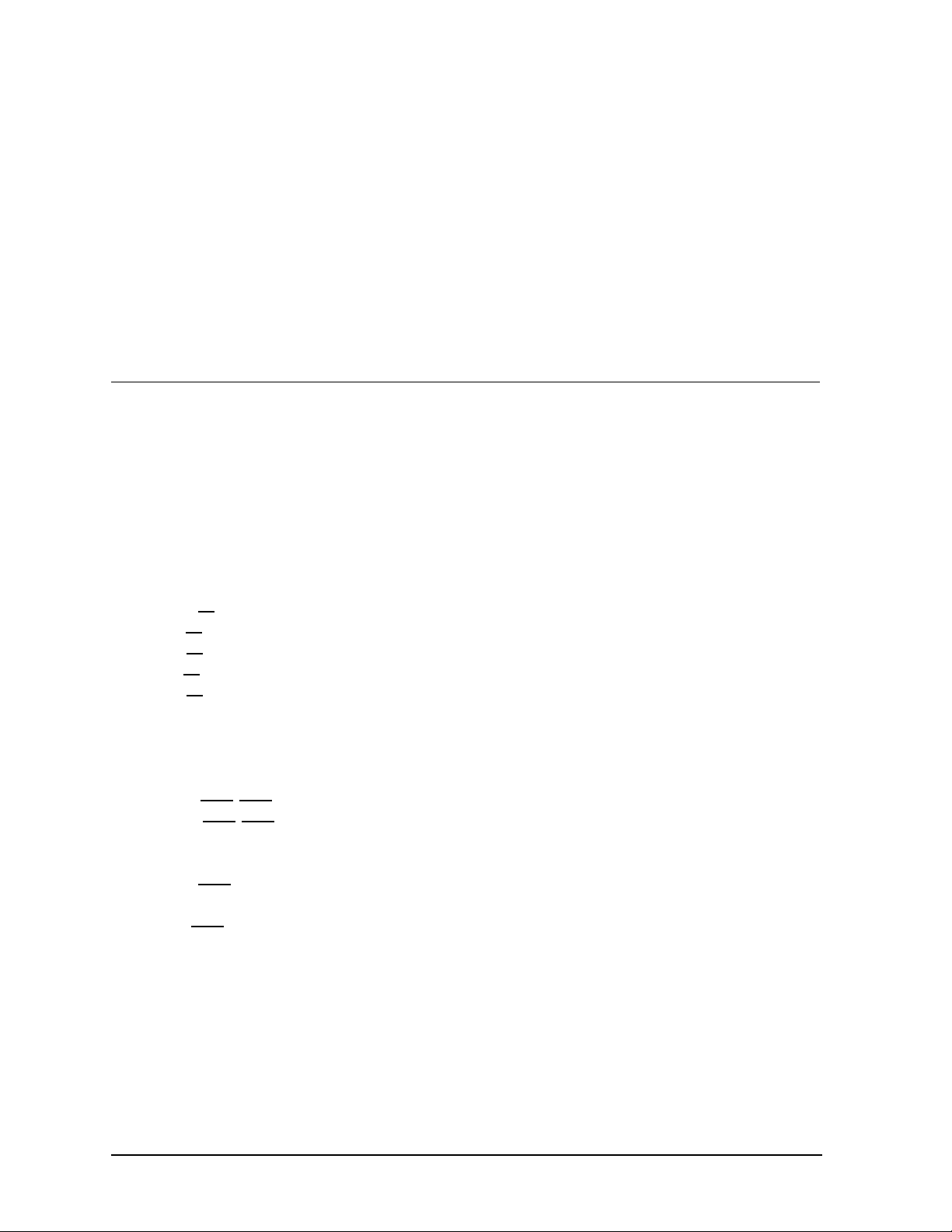
The serial number and model numbers can be found on the ID label, located on the display. This label
will look similar to the one shown in Figure 2. When calling Daktronics Customer Service, please have
this information available to ensure that your request is serviced as quickly as possible.
Figure 2: Display ID Label
Daktronics displays are built for long life and require little maintenance. However, from time to time,
certain display components will need replacing. The Replacement Parts List in Section 4.6 provides
the names and part numbers of components that may need to be ordered during the life of this display.
Following the Replacement Parts List is the Exchange/Replacement Procedure. Refer to these
instructions if any display component needs to be replaced or repaired.
1-2
Introduction
Page 9

Introduction
1-3
Page 10

1.2 Safety Precautions
1. Read and understand these instructions before installing.
2. Be sure that the display is properly grounded.
3. Disconnect power before working on the display.
4. Do not modify the displays or attach any panels or coverings to the display without the express
written consent of Daktronics, Inc.
5. Most products are equipped with a 3-wire grounding-type plug, a plug having a third
(grounding) pin. This plug will only fit into a grounding-type power outlet. This is a safety
feature. If you are unable to insert the plug into the outlet, contact a qualified electrician to
replace your obsolete outlet. Do not defeat the purpose of the grounding-type plug.
1.3 Network Concepts
Reference Drawings:
System Riser Diagram; RS/232................................................................Drawing A-91388
System Riser Diagram; RS/422................................................................Drawing A-91387
System Riser Diagram; Modem................................................................Drawing A-91386
V1500 System Riser Diagram...................................................................Drawing A-93904
The concept of using LED displays as a cost effective, high impact method of communication is rapidly
growing throughout many industries and businesses. The reasons for this growth are many, but the
need for additional features and complexity of multiple sign installations has emerged, and the
Daktronics display systems have been designed to meet those needs. The common thread to most
clients= requests is a means of programming and controlling a group of signs from a central control
point. Daktronics responded by developing a powerful system of interconnecting and controlling signs.
Great care has been taken to design products that will satisfy a wide variety of installations. Some of
the design goals of these systems include the following:
• Easy transfer of messages
• The ability to tell a sign in the network which message it should run
• The ability to determine the status of any sign on the network
• The ability to control multiple sign technologies on the same network
All of the programming features would seem insignificant if the installation of the systems could not be
accomplished with basic tools and without technical difficulty. Daktronics decided to use the very
popular and readily available RJ-11 connector. This connector is also used on modern home and office
telephone equipment.
All that is required for signal insta llation is standard six (6) conductor modular telephone wire. Tools
required for mounting the display depend on the location and size of the display. For some installations,
it may be possible to buy pre-terminated telephone cables for use with the displays.
There are four (4) network systems available: RS232, RS422, modem and TCP/IP.
RS232 Network
RS232 (EIA/TIA-232-E) is a standard communication interface that employs a single-ended serial
transmission scheme that uses a maximum cable length of 7.62 meters (25 feet). This interface
1-4
Introduction
Page 11

was designed for computer communication at short distances. All computers have an RS232
communications port. Refer to Drawing A-91388.
RS422 Network
RS422 (EIA/TIA-422-B) is a standard communication interface that utilizes a differential balanced
transmission scheme that uses a typical maximum cable length of 1.2 km (approximately 4000
feet). The main advantage to RS422 over RS232 is the longer cable length that is possible. A signal
converter is needed to convert the compute r’s RS232 to RS422. Refer to Drawing A-91387.
Modem Network
The modem is a standard communication interface that utilizes standard phone transmission lines.
The phone company assigns each phone line a number that the modem uses to communicate
between controller and display. Refer to Drawing A-91386.
TCP/IP Network
The TCP/IP protocol is an interface allowing the Ethernet network card (installed in the operator’s
computer) to communicate with the serial server via a Local Area Network (LAN). Information
for the individual displays is distributed from the serial server’s RS232 and output. Refer to
Drawing A-93904.
1.4 Display Overview
The Daktronics Indoor LED displays have been designed and manufactured for performance,
reliability, easy maintenance and lo ng life. The displays consist of an array of LED pixels. The
configuration of the LED pixels is dependent on the family of LED displays. The standard character is
seven pixels high by five pixels wide.
A typical system consists of a Windows-based personal computer (PC) running Venus 1500
software and one or more displays. The PC controls one ore more DataTrac displays. The displays are
offered as single-face displays, which are single-sided stand-alone units. They can become doublefaced by mounting the m back-to-back with a second unit.
The Venus 1500 is a software package that runs under Windows 3.1x or Windows 95 operating
systems on an IBM-compatible computer. Refer to the Venus 1500 controller manual, ED-12717, for
installation and maintenance of the Venus 1500 editing station.
DataTrac displays are character-based indoor LED displays that are available in monochrome red or
tri -color (red, green and amber) characters. This display family is for 5x7 single -stroke fonts and
graphic fonts. Daktronics offers the DataTrac displays with a 0.7@, 1.2@ or 2.1@ character in various
lengths. The DataTrac model numbers are described as follows: S-X00-LLL-CCC-DD
S
X00
LLL
CC
C
DD
= DataTrac Display
= 100 = Indoor Monochrome Red
200 = Indoor Tri-Color (Red, Green, Amber)
= Number of Lines Tall (4, 8 and 12 are available)
= Number of Characters per Line (18, 24, 30, 36, 42 or 48)
= Character Height (0.7”, 1.2” or 2.1”)
Introduction
1-5
Page 12

1-6
Introduction
Page 13

1.5 Definitions
Com Port: A Com Port is a connector on the back of the controller PC. The Com Port is used to
control the sign network through either a 9- or 25-pin serial connector.
Display Configuration: Display configuration refers to a display’s model number, address, etc.
This information will be automatically displayed when the display is powered up. Display configuration
is as follows:
1. Output Test (DDD’s)
2. Display Model Number (i.e. S-100-12-24-0.7)
3. Firmware Version
4. COM1 Configuration (typically V1500)
5. COM2 Configuration (either DataView or RTD)
6. Power Line Frequency (i.e. 60 Hz)
7. Display Address – displayed in binary code (i.e. 001)
8. Sign Name
9. Modem (if present)
Flipped Cable: The flipped cable is a six (6) conductor phone cable. Pin 1 of connector A connects
to pin 6 of connector B.
LAN: Local Area Network
Loop Back Test: The loop back te st is a troubleshooting test that connects the output to the input.
Contact Daktronics customer service for this test.
Module: A module is one unit of the display. A module for a 0.7@ display consists of 4 lines by 12
characters of LEDs. The 1.2@ and 2.1@ displays = modules consist of 4 lines by 6 characters.
Network: A network consists of multiple signs connected to each other. Up to 240 Venus 1500
controlled displays can exist on one network.
RS232: RS232 is a standard PC communication type with a maximum cable length of 25 feet (7.62
meters).
RS422: RS422 is a standard differential communication type with a maximum cable length of 4000
feet (1.2 kilometers).
RX LED: A RX LED is a LED on the signal converter that indicates if the display is sending data
back to the signal converter.
Serial Server: A serial server is a device used to obtain information off of a LAN.
Sign Address: The sign address is an identification number assigned to each sign of a network . The
control software uses the address to lo cate and communicate with each display. Displays that are on
the same network cannot have the same address.
Signal Cable Tester: The signal cable tester is used to test the cable connections and data
communication.
Introduction
1-7
Page 14
Signal Converter: The signal converter is a Daktronics supplied unit that converts the data from
RS232 to RS422. The signal converter is used in RS422 systems.
TCP/IP: The TCP/IP (Transmission Control Protocol/Internet Protocol) is a communications protocol
used for LANs.
TX LED: A TX LED is a LED on the serial converter that indicates the control PC is sending data to
the display.
Venus 1500: The Venus 1500 is a Daktronics designed, Windows-based software used to run the
displays.
1.6 Daktronics Nomenclature
To fully understand some Daktronics drawings, such as schematics, it is necessary to know how
various components are labeled in those drawings. You will find this information useful when trying to
communicate maintenance or troubleshooting efforts.
The label “A” on a drawing typically denotes an assembly. An assembly can be a single circuit board
or a collection of components that function together, usually mounted on a single plate or in a single
enclosure. Assemblies are divided into two types: those that route signal and those that route power.
In addition, the following labeling formats might be found on various Daktronics drawings:
• “TB??” denotes a termination block for power or signal cable.
• “F??” denotes a fuse.
• “E??” denotes a grounding point.
• “J??” denotes a power or signal jack.
• “P??” denotes a power or signal plug for the opposite jack.
Finally, Daktronics part numbers are commonly found on drawings. Those part numbers can be used
when requesting replacement parts from Daktronics Customer Service. Take note of the following part
number formats. (Not all possible formats are listed here.)
• “0P-????-????” denotes an individual circuit board.
• “0A-????-????” denotes an assembly, such as a circuit board and the plate or bracket to
which it is mounted. A collection of circuit boards wor king as a single unit may also carry an
assembly label.
• “W-????” denotes a wire or cable. Cables may also carry the assembly numbering format in
certain circumstances. This is especially true of ribbon cables.
• “F-????” denotes a fuse.
• “T-????” denotes a transformer
• “PR-?????-?” denotes a specially ordered part.
1-8
Introduction
Page 15
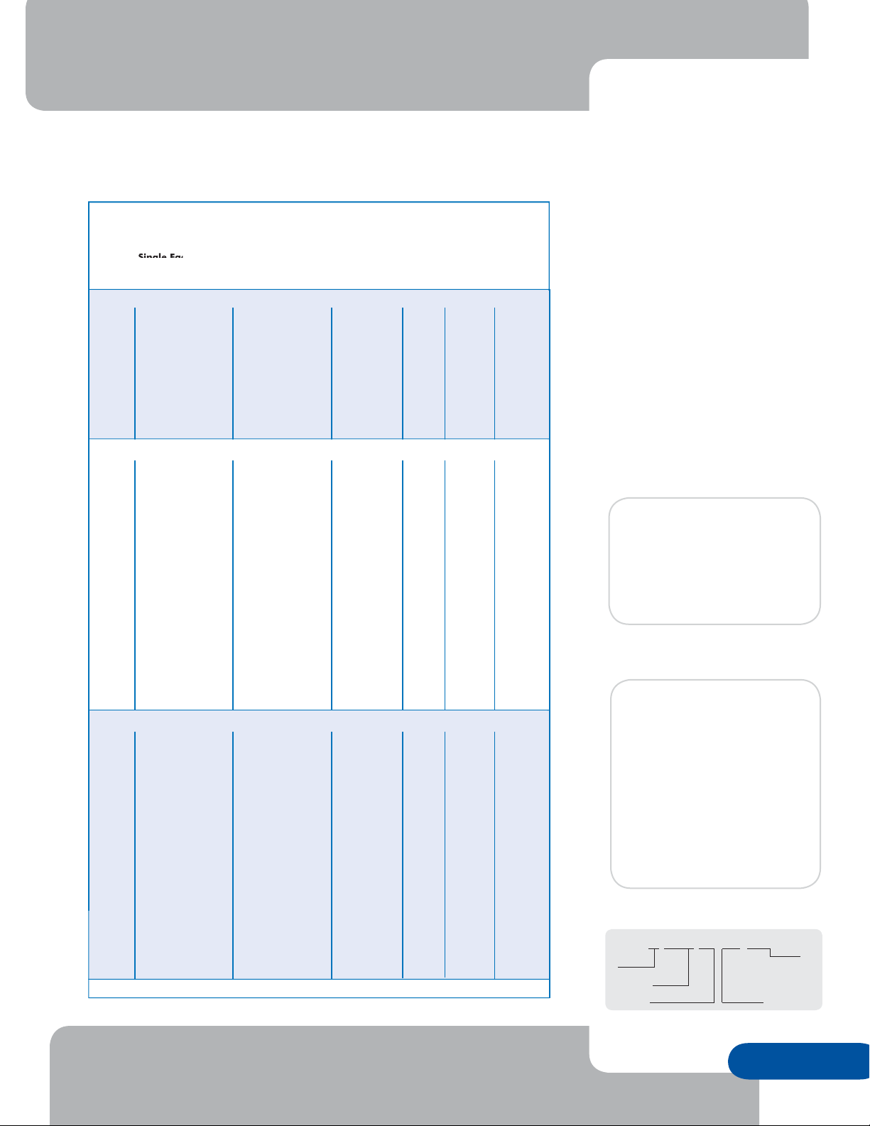
DataTrac™
Single Face Cabinet
RG Indoor Character-Based—S-100 and S-200 Series
DataTrac™ S-100 displays show text in red and S-200 displays show text in a combination
of red, green and amber characters. Both displays are programmed with Venus
display control software.
Model Specifications
(All Specifications are Approximate)
Matrix
Size
Feet -Inches
(H x W x D)
Single Face Cabinet
Meters
(H x W x D)
S-100 – 0.7" high characters
4x24
4x36
4x48
8x24
8x36
8x48
12x24
12x36
12x48
10" x 1'7" x 5"
10" x 2'3" x 5"
10" x 2'10" x 5"
1'4" x 1'7" x 5"
1'4" x 2'3" x 5"
1'4" x 2'10" x 5"
1'10" x 1'7" x 5"
1'10" x 2'3" x 5"
1'10" x 2'10" x 5"
.25 x .48 x .13
.25 x .69 x .13
.25 x .86 x .13
.41 x .48 x .13
.41 x .69 x .13
.41 x .86 x .13
.56 x .48 x .13
.56 x .69 x .13
.56 x .86 x .13
S-100 and S-200 – 1.2" high characters
4x18
4x24
4x30
4x36
4x42
4x48
8x18
8x24
8x30
8x36
8x42
8x48
12x18
12x24
12x30
12x36
12x42
12x48
11" x 2'4" x 5"
11" x 2'11" x 5"
11" x 3'6" x 5"
11" x 4'2" x 5"
11" x 4'9" x 5"
11" x 5'4" x 5"
1'6" x 2'4" x 5"
1'6" x 2'11" x 5"
1'6" x 3'6" x 5"
1'6" x 4'2" x 5"
1'6" x 4'9" x 5"
1'6" x 5'4" x 5"
2'1" x 2'4" x 5"
2'1" x 2'11" x 5"
2'1" x 3'6" x 5"
2'1" x 4'2" x 5"
2'1" x 4'9" x 5"
2'1" x 5'4"x 5"
.28 x .71 x .13
.28 x .89 x .13
.28 x 1.07 x .13
.28 x 1.27 x .13
.28 x 1.45 x .13
.28 x 1.63 x .13
.46 x .71 x .13
.46 x .89 x .13
.46 x 1.07 x .13
.46 x 1.27 x .13
.46 x 1.45 x .13
.46 x 1.63 x .13
.64 x .71 x .13
.64 x .89 x .13
.64 x 1.07 x .13
.64 x 1.27 x .13
.64 x 1.45 x .13
.64 x 1.63 x .13
S-100 and S-200 – 2.1" high characters
4x18
4x24
4x30
4x36
4x42
4x48
8x18
8x24
8x30
8x36
8x42
8x48
12x18
12x24
12x30
12x36
12x42
12x48
1'4" x 3'2" x 5"
1'4" x 4'1" x 5"
1'4" x 5'0" x 5"
1'4" x 5'11" x 5"
1'4" x 6'10" x 5"
1'4" x 7'8" x 5"
2'4" x 3'2" x 5"
2'4" x 4'1" x 5"
2'4" x 5'0" x 5"
2'4" x 5'11" x 5"
2'4" x 6'10" x 5"
2'4" x 7'8" x 5"
3'4" x 3'2" x 5"
3'4" x 4'1" x 5"
3'4" x 5'0" x 5"
3'4" x 5'11" x 5"
3'4" x 6'10" x 5"
3'4" x 7'8" x 5"
.41 x .97 x .13
.41 x 1.24 x .13
.41 x 1.52 x .13
.41 x 1.8 x .13
.41 x 2.08 x .13
.41 x 2.34 x .13
.71 x .97 x .13
.71 x 1.24 x .13
.71 x 1.52 x .13
.71 x 1.8 x .13
.71 x 2.08 x .13
.71 x 2.34 x .13
1.02 x .97 x .13
1.02 x 1.24 x .13
1.02 x 1.52 x .13
1.02 x 1.8 x .13
1.02 x 2.08 x .13
1.02 x 2.34 x .13
Additional matrix sizes are avail able
Measurements are approximate. For precise measurements, request a Daktronics shop drawing.
Single Face
Weight
Pounds (kg)
15 (7)
20 (9)
25 (11)
25 (11)
30 (14)
35 (16)
30 (14)
40 (18)
50 (23)
20 (9)
25 (11)
30 (14)
35 (16)
40 (18)
45 (20)
30 (14)
40 (18)
45 (20)
50 (23)
60 (27)
65 (29)
40 (18)
50 (23)
60 (27)
70 (32)
80 (36)
90 (41)
35 (16)
40 (18)
50 (23)
55 (25)
65 (29)
75 (34)
55 (25)
65 (29)
80 (36)
95 (43)
105 (48)
120 (54)
75 (34)
90 (41)
110 (50)
130 (59)
150 (68)
170 (77)
Char ac ters
per
Line
24
36
48
24
36
48
24
36
48
18
24
30
36
42
48
18
24
30
36
42
48
18
24
30
36
42
48
18
24
30
36
42
48
18
24
30
36
42
48
18
24
30
36
42
48
Character
Height
0.7"
0.7"
0.7"
0.7"
0.7"
0.7"
0.7"
0.7"
0.7"
1.2"
1.2"
1.2"
1.2"
1.2"
1.2"
1.2"
1.2"
1.2"
1.2"
1.2"
1.2"
1.2"
1.2"
1.2"
1.2"
1.2"
1.2"
2.1"
2.1"
2.1"
2.1"
2.1"
2.1"
2.1"
2.1"
2.1"
2.1"
2.1"
2.1"
2.1"
2.1"
2.1"
2.1"
2.1"
2.1"
®
1500
Max. Watts
per Face
100
150
190
190
280
370
280
420
550
140
180
220
260
300
350
260
350
430
510
590
680
390
510
630
760
880
1,000
140
180
220
260
300
350
260
350
430
510
590
680
390
510
630
760
880
1,000
S-100 & S-200
Technical Specifications
Character Heights:
S-100 – 0.7", 1.2" and 2.1"
S-200 – 1.2" and 2.1"
Color Capability:
S-100 – red
S-200 – RG: red, green and
amber
LEDs per Pixel: Monolithic block
Estimated LED Lifetime:
100,000+ hours
Viewing Angle:
140 degrees horizontal x
140 degrees vertical
Contrast Enhancement:
Polycarbonate face
Service Access: Front access
Control Software:
Venus
Power: 120 VAC single phase
Communication Options:
RS232, RS422, Modem and TCP/IP
Compliance Information: ETL Listed
Model Number Guide
®
1500
Ford Motor Company
Edison, New Jersey
8x42 matrix RG
Sysco Food Services
Fremont, California
12x42 matrix RG
S-200-12x24-1.2
Mod el
Se ries
Let ter
100 Red
200 RG
Number of Lines
Number of
Character
Blocks
per Line of
Display
Char ac ter
Height
WWW.DAKTRONICS.COM 888-DAKSIGN (888-325-7446)
Daktronics, Inc. 331 32nd Avenue, PO Box 5128, Brookings, SD 57006 Phone 605-697-4300 Fax 605-697-4700
e-mail: sales@daktronics.com DataTrac™ and Venus® are trademarks of Daktronics, Inc. Copyright © 2004 Daktronics, Inc.
SL041204-03025
Page 1 of 1
Page 16

Section 2: Mechanical Installation
LNote: Daktronics engineering staff must approve any changes made to the display. If any
modifications are made, detailed drawings of the changes must be submitted to Daktronics for
evaluation and approval, or the warranty may be void.
Refer to the appropriate shop drawing for your type of display during installation.
Reference Drawings:
Shop Drawing; S-***-4-24-0.7"..................................................................Drawing A-89791
Shop Drawing; S-***-4-36-0.7"..................................................................Drawing A-92153
Shop Drawing; S-***-4-48-0.7"..................................................................Drawing A-92154
Shop Drawing; S-***-8-24-0.7"..................................................................Drawing A-92155
Shop Drawing; S-***-8-36-0.7"..................................................................Drawing A-92156
Shop Drawing; S-***-8-48-0.7"..................................................................Drawing A-92157
Shop Drawing; S-***-12-24-0.7"................................................................Drawing A-89360
Shop Drawing; S-***-12-36-0.7"................................................................Drawing A-92158
Shop Drawing; S-***-12-48-0.7"................................................................Drawing A-92159
Shop Drawing; S-***-4-*-1.2".....................................................................Drawing A-96635
Shop Drawing; S-***-8-*-1.2".....................................................................Drawing A-96637
Shop Drawing; S-***-12-*-1.2"...................................................................Drawing A-96639
Shop Drawing; S-***-4-*-2.1".....................................................................Drawing A-77323
Shop Drawing; S-***-8-*-2.1".....................................................................Drawing A-77321
Shop Drawing; S-***-12-*-2.1"...................................................................Drawing A-77322
2.1 Support Structure Design
Support structure design depends on mounting methods, display size and weight. The structure design is
critical and should be done only by a qualified individual. It is the customer’s responsibility to ensure
that the structure and connectors are adequate. Daktronics is not responsible for the installations
or the structural integrity of support structures done by others.
2.2 Display Ventilation Requirements
Fresh air inlets and exhaust vents should not be obstructed in any way. Using the Daktronics suggested
mounting methods will ensure proper ventilation. If you are using a different mounting method, consult
a Daktronics sales representative for clearance requirements regarding your particular display. If
ventilation requirements are not met, the display warranty will be void.
Mechanical Installation
2-1
Page 17
2.3 Display Mounting
Reference Drawings:
Mtg. Detail; Top Hanging Mount, All Displays ............................................Drawing A-92315
Mtg. Detail; Rear Hanging Mount, 0.7” Displays........................................Drawing A-92292
Mtg. Detail; Rear Hanging Mount, 1.2” and 2.1” Displays..........................Drawing A-76158
It is the customer’s responsibility to ensure that the installation will meet local standards. The mounting
hardware must be capable of supporting all components to be mounted. Daktronics is not
responsible for the installations or the structural integrity of support structures done by others.
Daktronics recommends either a wall mount or a hanging mount method. A removable wall mounting
bracket and eyebolts for hanging are included with each display. Have all mounte d displays inspected
by a qualified structural engineer.
Hanging Mount
The DataTrac has two pre-drilled holes in the top of the
display for use in the hanging mounting method. To
hang a display refer to Drawing A-92315 and the
following instructions:
1. Remove the two retaining screws from the top
of the display using a 5/32" Allen wrench (refer
to Figure 3).
Figure 3: Removing Retaining Screws
2. Slide a washer over the threads of each eyebolt.
3. Insert the eyebolts into the pre-drilled holes on the display
(refer to Figure 4).
4. Hand-tighten the eyebolts.
Note: Hanging the display without using th e supplied eyebolts
will negate the warranty. Attaching or hanging anything from the
display will render the warranty null and void.
Wall Mount
The DataTrac has eight (8) or twelve (12) holes on the back of the
display for the attachment of the wall mounting clips. Refer to
Drawing A-92292 or Drawing A-76158 and the following instructions:
1. Using the #8-32 screws or ¼-20 bolts provided with the display, attach the mounting clips
to the rear of the display as shown (refer to Figure 5 and Figure 6). Use all clips
Figure 4: Eyebolt Insertion
Figure 5: Attaching the Wall Mounting Clip
2-2
Figure 6: Mounting Clip Placement; Rear View
Mechanical Installation
Page 18
supplied.
2. Mount the wall bracket or
brackets to the wall where the
display is to be located. Refer
to Drawing A-92292 or
Drawing A-76158 to
determine the location of the
bracket or brackets with
Figure 7: Mounting Bracket Placement; Rear View
respect to the display. Be sure the bracket is mounted to sufficiently support the
weight of the display. Have all mountings inspected by a qualified structural engineer.
3. Set the display on the wall-mounted bracket. The
bracket fits onto the wall mounting clips as shown in
Figure 7. Open the display as described in Section
4.1. Using two (2) #8 screws, fasten the mounting
bracket to the rear of the display (refer to Figure 8).
The display should now be attached to the wallmounted bracket.
Note: Mounting the display to the wall without using the
supplied mounting clips and bracket will negate the display
warranty. Attaching or hanging anything from the display will
render the warranty null and void.
Figure 8: Securing the
Mounting Bracket
Mechanical Installation
2-3
Page 19

Page 20
Section 3: Electrical Installation
3.1 Common Connectors
This display uses many different types of connectors for power and signal termination. Take special
care when disengaging any connector so as not to damage the connector, the cable or the circuit
board.
When pulling a connector plug from a jack, do not pull on the wire or cable; pull on the jack
itself. Pulling on the wires may damage the connector.
The following information presents some common connectors that may be encountered during display
maintenance. Not all of these connectors are found in every display.
1. Phone Jacks (RJ11/RJ45 Connectors):
RJ connectors, as seen in Figure 9, are similar to the telephone connectors found in
homes and are used on the ends of RJ45 cable. In order to remove this plug from the
jack, depress the small clip on the underside of the plug.
Before replacing an RJ connector, spray it with Deoxit™ contact cleaner to remove
any foreign matter that may cause signal problems. In addition, apply a generous
amount of Cailube™ protector paste to the plug before inserting it into the jack. This
paste will protect both the plug and the jack from corrosion.
2. Mate -n-LokJ Connectors:
The Mate -n-Lok connectors found in this display are white and
come in a variety of sizes. Circuit boards often used 9-pin Mate -n-Lok
connectors while four -pin connectors and two-pin connectors are often used for
power connection. Figure 10 shows a four -pin Mate-n-Lok connector. To
remove the plug form the jack, squeeze the plastics locking clasps of the side of
the plug and pull it from the jack.
3. Ribbon Cable Connectors:
Daktronics uses a variety of ribbon cables and ribbon cable connectors. Figure
Figure 10: Mate-nLok Connector
12 and Figure 11 illustrate two of the most commonly used ribbon cable
connectors. To disconnect ribbon cable connector #1,
squeeze the metal locking clips inward and pull the plug
out of the jack. To disconnect ribbon cable connector #2,
pull each of the plastic locking arms outward and remove
the plug.
Before replacing a ribbon cable connector, spray it with
Deoxit contact cleaner to remove any foreign matter that
may cause signal problems. In addition, apply a generous
amount of Cailube protector paste to the plug before
inserting it into the jack. This paste will protect both the
plug and the jack from corrosion.
Figure 12: Ribbon
Cable Connector #1
Figure 11: Ribbon
Cable Connector #2
Figure 9: RJ11/
RJ45 Connector
Electrical Installation
3-1
Page 21

3.2 Signal
Cables
The conductor connector used in the
network is an industry standard, 6-pin
RJ-11 or an 8-pin RJ-45. This
connector can be found on many
telephones and LANs.
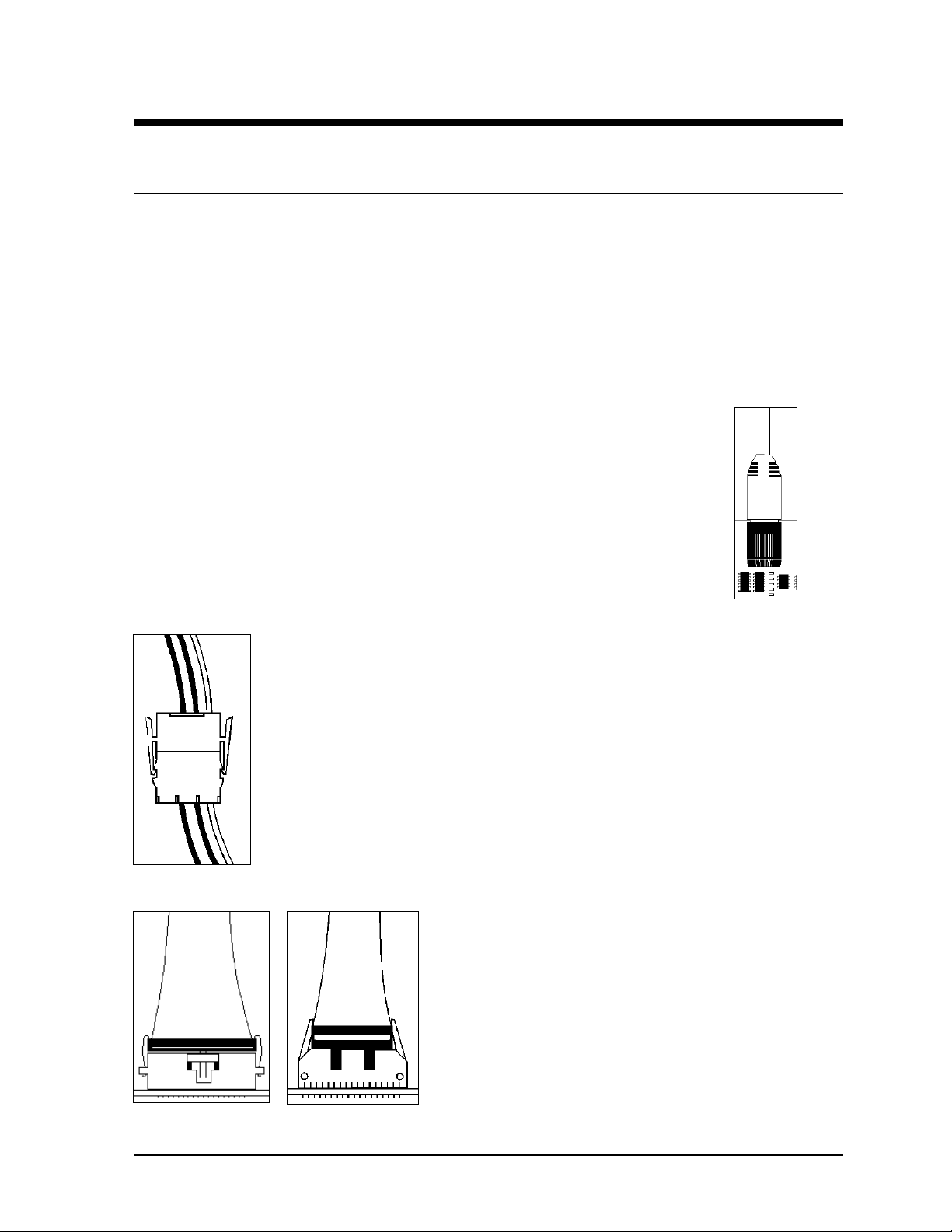
The cable used in the network is a
standard flat six -conductor telephone
cable (standard flipped cable). Refer
to Figure 13. This cable has one end that is the mirror image of the other end (i.e. the cable is
flipped). Refer to Figure 14 for a standard flipped cable.
Notice in Figure 14 that the color code on one connector must be made the opposite on the other
connector. When installing a network, it is not easy to remember in which direction the previous
end was oriented. One simple way to avoid confusion is to standardize the color code, having one
color for the connector going into the output of a sign and the opposite color for a connector going
into the in put of a sign. This will help ensure correct cabling since cables are always installed from
the output jack of one sign to the input jack of the next sign.
Figure 13: 6-Conductor RJ-11 Connector, 8-Conductor RJ-45
Connector and Cable
Figure 14: Flipped Cable with RJ Connectors
Installing an RJ Connector
Installing an RJ connector on the end of the conductor cable is a simple
task when the correct tools are used. The RJ crimping tool (Daktronics
part number TH-1033) performs two separate steps.
First, use the crimping tool to strip the outer insulation from the inner
wires. This does not result in bare wires since only the gray outer jacket is
removed. After correct stripping, the wire will appear as shown in Figure
Figure 15: Wire with
Outer Jacket Stripped
15.
The crimping tool is then used to crimp the RJ connector onto the cable. The RJ connector is
locked into a special socket in the tool. The stripped wire is inserted into the RJ connector. Finally,
the tool is squeezed like a pliers to crimp the connector onto the wire. This completes the
installation of an RJ connector onto the wire.
3-2
Electrical Installation
Page 22

Electrical Installation
3-3
Page 23

Pin-Outs
The RS422 jack’s pin out is as follows:
RJ11 RJ45 Function
1 N.C.
1 2 GROUND
2 3 D1OUT-P
3 4 D1OUT-N
4 5 D1IN-P
5 6 D1IN-N
6 7 GROUND
8 N.C.
3.3 Power
Power Requirements
Refer to the specifications sheet (SL-3025) for voltage and current requirements. The displays are
sufficiently powered by a 120VAC single-phase outlet.
Do not connect the display to any voltage other than that listed on the Daktronics product label
attached to the back of the display.
Grounding
Proper grounding is necessary for reliable equipment operation and provides some protection to the
equipment from damaging electrical disturbances. The displays are supplied with a power cord that
contains an earth ground conductor. Make sure to plug this cord into a grounded outlet. If the
proper grounding methods are not followed, the warranty will be void. KNote : Displays must be
earth grounded according to local electrical code.
Power Connection B Pluggable Cord Connected Displays
The DataTrac displays are supplied with a eight (8) foot power cor d. The socket-outlet should be
installed near the equipment and be easily accessible. Plug the power cord into the socket as
shown in Figure 16.
3-4
Figure 16: Power Cord Connection
Electrical Installation
Page 24

3.4 Computer to Sign
Reference Drawings:
System Riser Diagram; RS/232................................................................Drawing A-91388
System Riser Diagram; RS/422................................................................Drawing A-91387
System Riser Diagram; Modem................................................................Drawing A-91386
V1500 System Riser Diagram...................................................................Drawing A-93904
RS232 System
A RS232 system connects the first sign directly
to the computer with an adapter cable. The
adapter cable comes with both a 9 pin and a 25
pin connector. Refer to Drawing A-91388 and
the following steps.
1. Plug the 9-pin or 25-pin connector
(depending on your PC) to the PC’s
RS232 serial COM port.
2. Plug one end of the phone cable into
the adapter and the opposite end into
the “RS232 IN” jack on the rear of the
display (refer to Figure 17).
Note: The input connection is applicable for a RS232, RS422, modem or TCP/IP system. The
“SIGNAL IN” label will reflect the correct system.
The “RS232 IN” jack’s pin out is as follows:
Pin Function
1 RTS_OUT-P
2 RESET_OUT-P
3 TX_OUT-N
4 GND-N
5 RS_IN-N
6 DCD_IN-P
RS422 System
A RS422 system requires a signal converter to connect the first sign to the computer. Refer to
Drawing A-91387 and the following steps.
1. Plug the serial cable’s 25-pin connector into the signal converter as shown in Figure
17.
2. Plug either the 9-pin or the 25-pin connector (depending on your PC) into the RS232
COM port to be used.
3. Plug the signal converter’s power cord into a 120 VAC grounded outlet.
4. Plug a flipped phone cable into the “RS422 OUT” of the signal converter and the
opposite end into the “RS422 IN” of the first display.
Figure 17: Input Signal Cable Connection
Electrical Installation
3-5
Page 25

3-6
Electrical Installation
Page 26

The “RS422 IN” jack’s pin out is as follows:
Pin Function
1 N.C.
2 D1OUT-P
3 D1OUT-N
4 D1IN-P
5 D1IN-N
6 N.C.
Modem System
A modem system uses a standard phone line to connect the computer to the sign. At the display,
simply plug into a phone cable from the J-box into the jack labeled “PHONE IN” (the plug location
is at the same point as shown in Figure 17). Hook up the modem per the manufacturer’s
instructions, and then follow the Venus 1500 manual (ED-12717) to determine the modem’s
configuration. Refer to Drawing A-91386.
TCP/IP or LAN System
A LAN system requires a computer running on a LAN. Connect the serial server to the LAN.
The server has an RS232 output just as a PC would. Follow the steps for the setup of a RS232
system. Refer to Drawing A-93904.
3.5 Sign to Sign Connections
Reference Drawings:
System Riser Diagram; RS/232................................................................Drawing A-91388
System Riser Diagram; RS/422................................................................Drawing A-91387
System Riser Diagram; Modem................................................................Drawing A-91386
V1500 System Riser Diagram...................................................................Drawing A-93904
The sign-to-sign connections are the same for the
RS232 system, RS422 system, modem system and
TCP/IP. Refer to the riser diagrams listed above.
When wiring a sign to sign network, the cable and
connectors discussed earlier in this section are
used. Pay special attention to the information
regarding flipped cables to help ensure a successful
installation. The best method of wiring the signs
together is to start at the first sign, as it is
designated to begin the network.
Figure 18: Output Signal Cable Connection
1. Plug the cable into the “SIGNAL OUT” output jack of the first sign (refer to Figure 18) and
the other end of the cable into the input jack of the next sign.
2. Continue this procedure throughout the network. When the wiring is complete, the last sign will
have nothing in the output jack.
Electrical Installation
3-7
Page 27

3-8
Electrical Installation
Page 28

Section 4: Maintenance & Troubleshooting
IMPORTANT NOTES:
1. Disconnect power before any repair or maintenance work is done on
the display!
2. Any access to internal display electronics must be made by qualified
service personnel.
The DataTrac displays are FRONT ACCESS. The components within the displays are not field
repairable. In most cases, it is easiest to completely replace the failed part or return it to Daktronics for
repair.
Reference Drawings:
Schematic; S-***-4**-0.7..........................................................................Drawing B-89763
Schematic; S-***-8**-0.7..........................................................................Drawing B-89764
Schematic; S-***-12**-0.7........................................................................Drawing B-89765
Schematic; S-***-4-**-1.2/2.1...................................................................Drawing B-91350
Schematic; S-***-8-**-1.2/2.1...................................................................Drawing B-91585
Schematic; S-***-12-**-1.2/2.1.................................................................Drawing B-91586
4.1 Opening the Display
To open the DataTrac display:
1. Remove the socket head screws from the face panel using a 9/64" Allen wrench (refer to
Figure 19). There are two screws on each side of the display.
2. Gently pull the face panel from the body of the sign. The display opens as shown in Figure
20. The LED module panels can now be seen.
Figure 19: Removing the
Face Panel Screws
Maintenance &
Troubleshooting
Figure 20: Face Panel Partially
Removed
4-1
Page 29

4.2 Accessing the Interior of the Display
1. Using a #2 Philips screwdriver, turn the screws securing the LED module panel to the cabinet
of the display one -quarter turn counter-clockwise (refer to Figure 21 and Figure 22). The
screws are designed to remain in the LED module flanges, but release from the cabinet.
Figure 21: Loosening of 1/4-Turn Fasteners
(0.7")
2. Gently pull the LED module panel from the
body of the display. It will come forward as a
complete unit. Note: Use caution when
removing the LED module panel. The ribbon
cable connecting the LEDs to the inside of the
display will still be connected. Refer to Figure
23 and Figure 24.
Figure 22: Loosening of 1/4-Turn
Fasteners (1.2" & 2.1")
Figure 23: Removing LED Module Panel (0.7")
4-2
Figure 24: Removing LED
Module Panel (1.2" & 2.1")
Maintenance &
Troubleshooting
Page 30

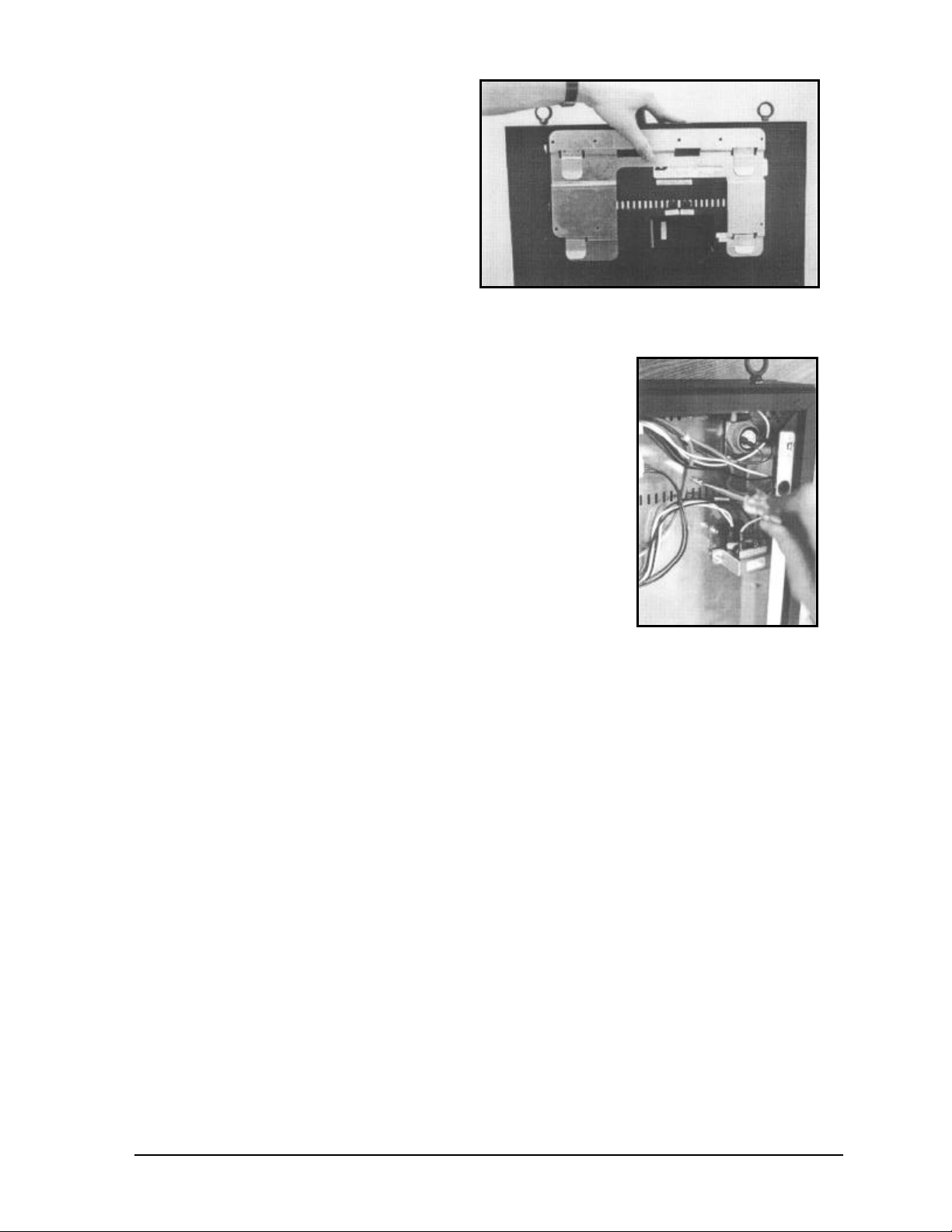
3. To completely remove the LED module
panel from the cabinet of the display, spread
the clasps of the 25-pin connector on the
rear side of the panel. Gently pull the cable
to disconnect it. Next, disconnect the four pin power connector. The power cable is
released by squeezing the tabs on each side
of the connector (refer to Figure 25).
Figure 25: Disconnecting LED Module Panel
Power Cable
4.3 Display Interior
Once the LED module panel is removed, the display interior is visible. Various internal components,
including the display controller, the modem (when applicable), the light detector, the fan (when
applicable), LED modules, the power supplies and the buzzer are now accessible for repair or
replacement.
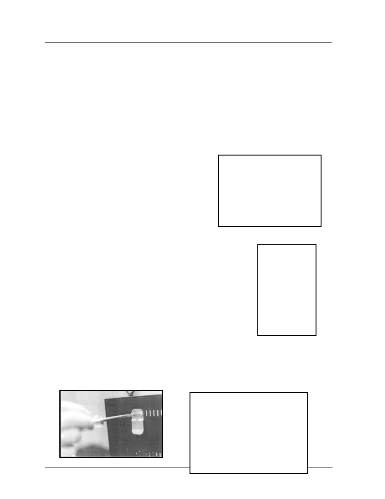
LED Module Replacement
If any LED modules fail, the recommended procedure is to replace the failed module or send it to
Daktronics or a certified dealer for repair. Refer to Section 4.7 for information on packaging
components for shipment.
To remove an individual LED module:
1. Disconnect the signal connection from the failed module. Gently pull the 25-pin ribbon
cable from the failed module (refer to Figure 26).
2. Disconnect the power supply (refer to Figure 27). Press the tabs on each side of the
four-pin connector to release it.
Figure 26: Disconnecting Signal from a Module
(0.7” Display Shown)
Maintenance &
Troubleshooting
Figure 27: Disconnecting a Power Supply from
a Module (0.7" Display Shown)
4-3
Page 31

3. Each module is held in place by #6 screws. Using a nut-driver, remove the module screws
from the panel (refer to Figure 28 and Figure 29).
Figure 28: Loosening LED Module Attachment
Screws (0.7")
Figure 29: Loosening LED Module Attachment
Screws (1.2" & 2.1")
4. Gently pull the failed module to remove it from the panel (Figure 30 and Figure 31).
Reverse the previous steps to attach a new module.
Figure 30: LED Module Removal (0.7")
Figure 31: LED Module
Removal (1.2" & 2.1")
Power Supply Replacement
Power to the LED modules and fans (8 and 12 line models only) is provided by small 5-volt power
supplies. Each power supply can support two modules. In 0.7" displays, they are located on the
rear side of the LED module panel. The 1.2" and 2.1" displays have the power supplies mounted to
the back sheet within the display cabinet.
0.7" Displays
To remove a power supply that has failed, first take off the
LED module opposite of the failed power supply as
described in LED Module Replacement, above.
Each power supply is secured to the module panel with two
(2) 3x10 metric screws as shown in Figure 32. Use a #1
Philips head screwdriver to remove the screws.
Figure 32: Loosening Power
Supply Screws (0.7")
4-4
Maintenance &
Troubleshooting
Page 32

1.2" & 2.1" Displays
To remove a power supply that has
failed, first remove the LED module in
front of the failed power supply as
described in LED Module
Replacement.
Each power supply is attached to a
power supply plate by two (2) 3x10
metric screws. The plate is secured to
the back sheet by two (2) #6 screws
and nuts as shown in Figure 33. Use a
Figure 33: Power Supply & Plate (1.2" & 2.1" Displays)
5/16” wrench to remove the #6 nuts
(the screws do not need to be removed).
Lift the power supply and plate off the #6 screws. The metric screws securing the power
supply to the plate are now accessible. Use a #1 Philips head screwdriver to remove the
screws and free the power supply.
Both 0.7” and 1.2/2.1” Displays
Disconnect the power cables as shown in Figure 34. The power supply is now fully released
and ready for replacement. Follow the previous steps in reverse order to reattach the new
power supply. Refer to your display’s schematic for the proper wiring configuration.
Maintenance &
Troubleshooting
Figure 34: Power Supply Cable Connections
4-5
Page 33

Display Controller
Temp
Light
OUT
IN
POWER
J1 Phone
The display controller is mounted to the rear of the display cabinet, near the top left corner as
viewed from the front for 0.7" displays (refer to Figure 35) and in the bottom left corner for 1.2"
and 2.1" displays. The controller receives information from the computer, interprets it and activates
the appropriate LEDs on the display.
DIP Switches
DS1
+5V
DS2
RUN
MDC
J1 J2 J3
Light Detector
Sensor
DS3
Buzzer
J2 J3
RS422
Detector
RS422
Figure 35: Display Controller
The display controller also has a set of eight (8) switches by which an address can be set using
standard binary code (refer to Section 4.4).
To replace a failed controller, first dis connect all attached cables. LTake note of their orientation.
Remove all #6 connecting screws. If the address switches are used, take note of the switch
configuration and set the same address on the new controller. Attach the new controller using
#6-32 Screws.
Modem
If the display was ordered with a modem, its location depends
Power
LED
Power
Connection
upon the display model: in 0.7" displays, it will be located in the
top frame of the display cabinet, near the display controller
(refer to Figure 36); or in 1.2" and 2.1" displays, it will be
mounted below the display controller. The modem is used in
lieu of a direct communication line with the computer.
The modem is held in place with the use of plastic rails known
Active
LED
as a “snap track.” To replace a failed modem, disconnect all
attached cables and carefully “snap” it out of the rails. Insert
the new modem by first laying one end into the rails of the
RS/232
OUT
Figure 36: Modem
IN
“snap track,” then pivot it up and snap into place (refer to
IN
4-6
Figure 37: Installation of Modem
Maintenance &
Troubleshooting
Page 34

Figure 37).
Fans (0.7" Display, 8 & 12 Lines Only)
In the 0.7" models, coolin g fans are located near the
bottom of the cabinet of the 8 and 12 line displays (the
4 line displays do not contain fans). The fan filters
should be removed and rinsed with water periodically
to clean any dust or debris that may accumulate during
use. If a fan fails, it must be removed and replaced
with a new fan.
To remove a filter for cleaning, first disconnect the
fan’s power supply. The filter lies between the fan and
the finger guard.
Gently remove the finger guard (refer to Figure 38).
The filter will now be easily accessible. Rinse the filter
Figure 38: Removing Fan Finger Guard
with warm water and allow it to dry before replacing it on the fan.
It is not recommended to operate the fan without
the filter or finger guard in place.
The fan can be removed by first taking off the finger
guard and filter. Each fan is held in place with four (4)
#6-32 by 1-1/2" long screws. Use a flat-head
screwdriver to remove the screws and release the fan
from the back sheet. Use the same screws to attach
the new fan. Replace the filter and finger guard.
Figure 39: Fan, Filter & Fan Cover
Light Detector
A light detector is located near the top of the display in the right support flange for 0.7" displays,
and in the bottom left flange for 1.2" and 2.1" displays. The light detector is used to measure light
levels outside the display and, when enabled through the Venus 1500 software, adjusts the
brightness level of the LEDs appropriately.
The light detector is mounted on a support
flange. To replace the light detector, first
remove the #6 screws from the support flange
(refer to Figure 40).
Disconnect the light detector’s wire to the
display controller. The light detector is attached
to the support flange with #4 screws, standoffs
and nuts. Remove the failed light detector from
the support flange.
Figure 40: Removing the Light Detector
Maintenance &
Troubleshooting
4-7
Page 35

Fuse
The MDL-7 fuse is located in the left end of the cabinet, near the display
controller (refer to Figure 41).
To replace the fuse, push and turn the fuse cap, insert the new fuse into the
cap and reattach.
Figure 41: Fuse
4.4 Controller Address and Test Mode
The controller has a set of “DIP” switches on the side of the controller as shown in Figure 35. These
switches set the hardware address. When replacing a controller board, be sure to set the DIP switches
in the same address configuration as the defective controller.
Note: A test mode can be activated by setting the DIP switches to address 0 (turn all the switches to
OFF by flipping them toward the printed switch numbers). The display’s power must be downed, and
then reconnected to run the test mode.
Switch 8 Switch 7 Switch 6 Switch 5 Switch 4 Switch 3 Switch 2 Switch
Off
Off
Off
Off
Off
Off
Off
Off
Off
Off
Off
...
On
Off
Off
Off
Off
Off
Off
Off
Off
Off
Off
Off
...
On
Off
Off
Off
Off
Off
Off
Off
Off
Off
Off
Off
...
On
Off
Off
Off
Off
Off
Off
Off
Off
Off
Off
Off
...
On
Off
Off
Off
Off
Off
Off
Off
On
On
On
On
...
Off
Off
Off
Off
On
On
On
On
Off
Off
Off
Off
...
Off
Off
On
On
Off
Off
On
On
Off
Off
On
On
...
Off
1
On
Off
On
Off
On
Off
On
Off
On
Off
On
...
Off
Address
1
2
3
4
5
6
7
8
9
10
11
…
240
4-8
Maintenance &
Troubleshooting
Page 36

4.5 Troubleshooting
This section contains some symptoms that may be encountered with the LED displays. Possib le
remedies are provided. This list does not include every possible problem, but does represent some of
the more common situations that may occur.
Symptoms/Conditions Possible Cause/Remedy
Cannot communicate with the display. • Check flipped phone cable co nnections.
• Check display configuration.
• Check Venus 1500 configuration.
• Check signal converter TX & RX LEDs
• Contact Daktronics Customer Service
Display will not run. • Check power cord.
• Power down, then power up the display.
• Contact Daktronics Customer Serv ice.
Entire display is garbled or a section of
the display is bad.
Section of the display network is not
working.
Note: The display configuration will be shown on power up and will contain the following information:
1. Output Test (DDD=s)
2. Display Model Number (i.e. S-100-12-24-0.7)
3. Firmware Version
4. COM1 Configuration (typically V1500)
5. COM2 Configuration (either DataView or RTD)
6. Power Line Frequency (i.e. 60 Hz)
7. Display Address--displayed in binary code (i.e. 001)
8. Sign Name
9. Modem (if present)
• Power down and then power up the display.
• Contact Daktronics Customer Service.
• Bad input on first bad display.
• Bad output on last good display.
• Switch the suspect display with a known good
display.
• Contact Daktronics Customer Service.
Maintenance &
Troubleshooting
4-9
Page 37

4.6 Replacement Parts
Common Parts (All Models)
Part Description Daktronics Part No.
Power Supplies, 5V A-1499
Cable; PC DB9-RJ11 0A -1115-0042
Cable; PC EB25-RJ11 0A -1115-0044
Controller (RS232) 0A -1120-0477
Controller (RS422) 0A -1120-0478
Signal Converter 0A -1127-0237
25’ RJ11 Cable W-1265
100’ RJ11 Cable 0A -1146-0002
500’ RJ11 Cable 0A -1146-0003
1000’ RJ11 Cable 0A -1146-0004
Internal Modem 0P-1146-0003
Light Detector 0P-1151-0002
Buzzer DS-1357
Fuse, MDL -7 F-1031
Venus 1500 Manual ED-12717
DataTrac Manual ED-10191
RJ11 Connector P-1071
120V Transformer T-1072
Crimp Tool TH-1033
Power Cord W-1181
Signal Converter Serial Cable W-1363
Six-Conductor Wire W-1368
Serial Server A-1557
10’ Patch Cable W-1383
0.7" Display
The list below only gives parts used on the 0.7" displays.
Part Description Daktronics Part No.
Module; 0.7” Mono Red 0A -1120-0024
Module; 0.7” Mono. Green 0A -1120-0127
Fan B-1014
Fan Filter EN-1705
1.2" Display
The list below only gives parts used on the 1.2" displays.
Part Description Daktronics Part No.
Module; 1.2” Mono Red 0A -1120-0002
Module; 1.2” Tri-Color 0A -1120-0022
4-10
Maintenance &
Troubleshooting
Page 38

Fuse; MDL -3 F-1042
2.1" Display
The list below only gives parts used on the 2.1" displays.
Part Description Daktronics Part No.
Module; 2.1” Mono Red 0A -1120-0003
Module; 2.1” Tri-Color 0A -1120-0023
Fuse; MDL -3, 250V F-1042
4.7 Daktronics Exchange/Repair & Return Programs
To serve customers’ repair and maintenance needs, Daktronics offers both an exchange and a repair
and return program. The exchange program reduces down time by providing timely replacement of key
components. This service is provided to qualified customers who follow the program guidelines
explained below. It is our pleasure to provide this service to ensure you get the most from your
Daktronics products. Please call our Help Desk (1-877 / 605-1113) if you have any questions regarding
the exchange program or any other Daktronics service.
When you call the Daktronics Help Desk, a trained service technician will work with you to solve the
equipment problem. You will work together to diagnose the problem and determine which exchange
replacement part to ship. If, after you make the exchange, the equipment still causes problems, please
contact our Help Desk immediately.
If the replacement part fixes the problem, package the defective part in the same packaging the
replacement part arrived in, fill out and attach the enclosed UPS shipping document and RETURN
THE PART TO DAKTRONICS. (You may use the same box and packing the exchange part was
sent in.) This will speed up the transaction and alleviate confusion when the failed component arrives at
Daktronics. (Daktronics expects immediate return of the exchange part if it does not solve the
problem.) For most equipment, you will be invoiced for the replacement part at the time it is shipped.
This invoice is due when you receive it.
Daktronics reserves the right to refuse equipment that has been damaged due to acts of nature or
causes other than normal wear and tear.
If the defective equipment is not shipped to Daktronics within 30 working days from the invoice
date, it is assumed you are purchasing the replacement part and you will be invoiced for it. This
second invoice represents the difference between the exchange pr ice and the purchase price of the
equipment. This amount is due when you receive the second invoice. If you return the exchange
equipment after 30 working days from invoice date, you will be credited for the amount on the second
invoice minus a restocking fee.
@To avoid a restocking charge, please return the defective equipment within 30 days from
the invoice date.
Daktronics also offers a Repair and Return program for items not subject to exchange.
Where to Send: To return parts for service, contact your local representative prior to shipment to
acquire a Return Material Authorization Number (RMA#). If you have no local representative, call the
Maintenance &
Troubleshooting
4-11
Page 39

Daktronics Help Desk for the RMA#. This will expedite the receiving process.
Packaging for Return: Package and pad the item well so that it will not be damaged in shipment.
Electronic components such as printed circuit boards should either be installed in an enclosure or should
be put in an anti-static bag before boxing. Please enclose your name, address, phone number and a
clear description of symptoms.
Mail: Daktronics, Inc., Customer Service
PO Box 5128
331 32nd Avenue
Brookings, SD 57006
Phone: Daktronics Help Desk: 1-877 / 605-1113 (toll free)
or 1-605 / 697-4034
Customer Service Fax: 1-605 / 697-4444
e -mail: helpdesk@daktronics.com
4-12
Maintenance &
Troubleshooting
Page 40

Appendix A: Optional Temperature Sensor
The DataTrac displays may be ordered with
an optional temperature sensor. Follow the
supplied mounting instructions to attach the
temperature sensor and housing.
The temperature sensor cable connects to the
back of the display using the removable green
jack (refer to Figure 42).
Figure 42: Temperature Sensor Cable Connection
The pin orientation of the jack is shown in Figure 43.
Figure 43: Pin Orientation
Connect the temperature sensor cable to the jack as follows:
Display
Pin 1 Green P
Pin 2 White N
Pin 3 Red +V
Pin 4 Black GND
Pin 5 Bare N/A
Appendix A: Optional
Temperature Sensor
Cable
Wires
Temperature
Sensor
A-1
Page 41

Page 42

Appendix B: Reference Drawings
System Riser Diagram; RS/232......................................................................Drawing A-91388
System Riser Diagram; RS/422......................................................................Drawing A-91387
System Riser Diagram; Modem......................................................................Drawing A-91386
V1500 System Riser Diagram.........................................................................Drawing A-93904
Mtg. Detail; Top Hanging Mount.......................................................................Drawing A-92315
Mtg. Detail; Rear Hanging Mount, .7”...............................................................Drawing A-92292
Mtg. Detail; Rear Hanging Mount, 1.2” and 2.1”...............................................Drawing A-76158
Shop Drawing; S-***-4-24-0.7"........................................................................Drawing A-89791
Shop Drawing; S-***-4-36-0.7"........................................................................Drawing A-92153
Shop Drawing; S-***-4-48-0.7"........................................................................Drawing A-92154
Shop Drawing; S-***-8-24-0.7"........................................................................Drawing A-92155
Shop Drawing; S-***-8-36-0.7"........................................................................Drawing A-92156
Shop Drawing; S-***-8-48-0.7"........................................................................Drawing A-92157
Shop Drawing; S-***-12-24-0.7"......................................................................Drawing A-89360
Shop Drawing; S-***-12-36-0.7"......................................................................Drawing A-92158
Shop Drawing; S-***-12-48-0.7"......................................................................Drawing A-92159
Shop Drawing; S-***-4-*-1.2"...........................................................................Drawing A-96635
Shop Drawing; S-***-8-*-1.2"...........................................................................Drawing A-96637
Shop Drawing; S-***-12-*-1.2".........................................................................Drawing A-96639
Shop Drawing; S-***-4-*-2.1"...........................................................................Drawing A-77323
Shop Drawing; S-***-8-*-2.1"...........................................................................Drawing A-77321
Shop Drawing; S-***-12-*-2.1".........................................................................Drawing A-77322
Schematic; S-***-4**-0.7................................................................................Drawing B-89763
Schematic; S-***-8**-0.7................................................................................Drawing B-89764
Schematic; S-***-12**-0.7..............................................................................Drawing B-89765
Schematic; S-***-4-**-1.2/2.1.........................................................................Drawing B-91350
Schematic; S-***-8-**-1.2/2.1.........................................................................Drawing B-91585
Schematic; S-***-12-**-1.2/2.1.......................................................................Drawing B-91586
Appendix B:
Reference Drawings
B-1
Page 43

Page 44

Page 45

Page 46

Page 47

Page 48

Page 49

Page 50

Page 51

Page 52

Page 53

Page 54

Page 55

Page 56

Page 57

Page 58

Page 59

Page 60

Page 61

Page 62

Page 63

Page 64

Page 65

Page 66

Page 67

Page 68

Page 69

Page 70

Page 71

 Loading...