

Page 1

Radar Gun
Speed of Pitch Interfaces
Configuration Manual
ED-12224 Rev 5 – 15 October 2012
201 Daktronics Drive PO Box 5128 Brookings, SD 57006-5128
Tel: 1-800-DAKTRONICS (1-800-325-8766) Fax: 605-697-4746
www.daktronics.com
Page 2

Page 3

ED-12224
Product 1157
Rev 5 – 15 October 2012
DAKTRONICS, INC.
Copyright 2003-2012
All rights reserved. While every precaution has been taken in the preparation of this manual, the publisher
assumes no responsibility for errors or omissions. No part of this book covered by the copyrights hereon may be
reproduced or copied in any form or by any means – graphic, electronic, or mechanical, including photocopying,
taping, or information storage and retrieval systems – without written permission of the publisher.
All Sport® and Venus® are trademarks of Daktronics, Inc. Other trademarks used in this manual are the property of their
respective owners.
Page 4

Page 5

Table of Contents
Section 1: Introduction ............................................................................................................................ 1
1.1 General Pitch & Speed Information ...................................................................................... 1
1.2 Resources .................................................................................................................................. 1
Section 2: Radar Gun Placement & Mounting .................................................................................... 3
Section 3: Wired Speed of Pitch Configurations ................................................................................ 5
3.1 Interface Configurations ........................................................................................................ 5
Kit #1: Remote Radar Gun – Current Loop Scoreboard & RTD ................................ 5
Kit #2: Remote Radar Gun – Current Loop Scoreboard & RS-232 RTD ................... 6
Kit #3: Radar Gun Near All Sport – Current Loop Scoreboard & RS-232 RTD ....... 7
Kit #4: Radar Gun Near All Sport – Current Loop Scoreboard & RTD .................... 7
Section 4: Radio Speed of Pitch Configurations ................................................................................. 9
4.1 Radio Settings .......................................................................................................................... 9
4.2 Interface Configurations ........................................................................................................ 9
Kit #1: Remote Radar Gun – Radio Scoreboard & Current Loop RTD ................... 10
Kit #2: Remote Radar Gun – Radio Scoreboard & RS-232 RTD .............................. 10
Kit #3: Radar Gun Near All Sport – Radio Scoreboard & RS-232 RTD .................. 11
Kit #4: Radar Gun Near All Sport – Radio Scoreboard & Current Loop RTD ...... 12
Section 5: Troubleshooting ................................................................................................................... 13
5.1 Troubleshooting .................................................................................................................... 13
5.2 Replacement Parts ................................................................................................................. 14
Appendix A: Reference Drawings ............................................................................................................ 15
Table of Contents i
Page 6

Page 7
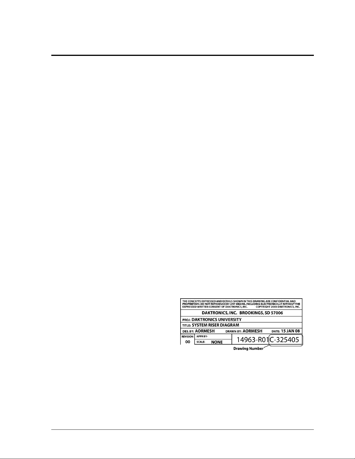
Figure 1: Daktronics Drawing Label
Section 1: Introduction
This manual explains the installation of several baseball speed of pitch systems. By connecting a
JUGS radar gun to an All Sport 5000 control console, the user is able to output data to Daktronics
scoreboards, matrix display controllers (Venus, Show Control), and the Daktronics Scoring-Timing
Interface (DSTI). This manual is not specific to a particular installation.
Important Safeguards:
Please read and understand all instructions before beginning the installation process.
Do not drop control equipment or allow it to get wet.
Do not disassemble control equipment; failure to follow this safeguard will make the
warranty null and void.
Disconnect display power when not in use or when servicing.
Disconnect display power before servicing power supplies to avoid electrical shock.
Power supplies run on high voltage and may cause physical injury if touched while
powered.
Project-specific information takes precedence over any other general information found in
this manual.
1.1 General Pitch & Speed Information
Section 5 of the All Sport 5000 control console manual (ED-11976) contains complete
instructions for operating the Pitch & Speed mode. Drawing A-130895 in Appendix A shows
the All Sport insert (LL-2482) used to operate this mode.
The manufacturers of the Jugs and Stalker radar guns also provide fully detailed operating
instructions in their respective manuals.
1.2 Resources
Figure 1 illustrates a Daktronics
drawing label. The drawing number is
located in the lower-right corner of a
drawing. This manual refers to
drawings by listing the last set of digits
and the letter preceding them. In the
example, the drawing would be
referred to as Drawing C-325405.
Reference Drawing:
System Riser Diagram ........................................................................... Drawing C-325405
Daktronics identifies manuals by the DD or ED number located on the cover page of each
manual. For example, this manual would be referred to as ED-12224.
Introduction 1
Page 8

Page 9
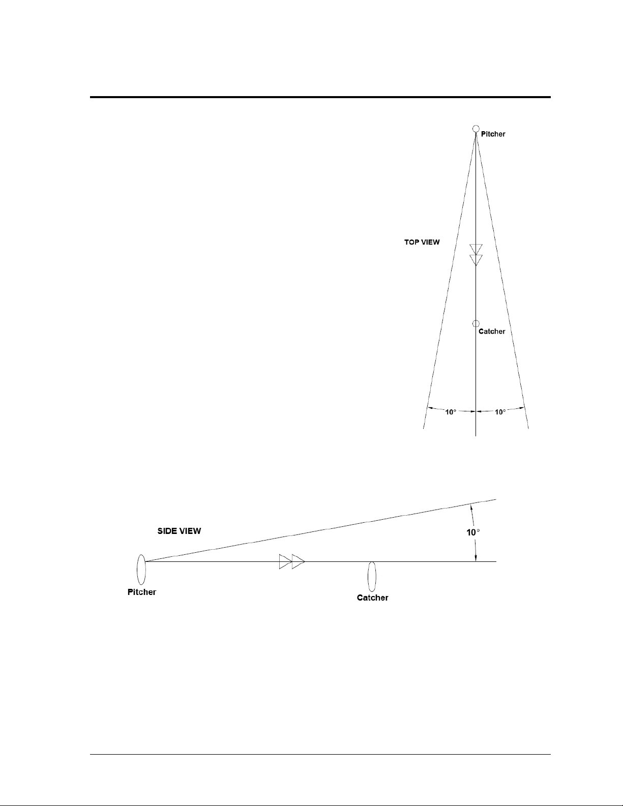
Figure 2: Radar Gun Placement,
Horizontal Angle
Figure 3: Radar Gun Placement, Vertical Angle
Section 2: Radar Gun Placement & Mounting
Refer to Figure 2 and Figure 3 for general placement
guidelines. Refer to the gun manufacturer's manual for
precise placement. Radar gun should be located no
more than 300' (91 m) from pitcher’s mound.
If a radar gun is located in a control room, the gun may
not read correct speeds through glass and tinted glass.
Note: Daktronics does not provide any standard
enclosure or rain shield for radar guns.
The Jugs radar gun package includes both a tripod
(preferred) and a wall mount bracket. Refer to Drawing
B-1023369 in Appendix A for instructions on how to
attach a radar gun to these devices.
Note: The tripod can be set as low as 22.5" (570 mm)
to not block the view of fans. It can also be set as high
as 55" (1390 mm) to provide a good angle for
accurate speed measurements.
If the gun is still off angle after mounting, speed adjust
calculations can be performed to offset this. Refer to the
instructions in Drawing A-243741 in Appendix A and
enter the final coefficient value into the All Sport console.
Radar Gun Placement & Mounting 3
Page 10

Page 11

Interface Kit Description
Part #
#1
Radar gun remote from All Sport;
wired scoreboard feed and current loop RTD
0A-1196-0032
#2
Radar gun remote from All Sport;
wired scoreboard feed and RS-232 RTD
0A-1196-0033
#3
Radar gun within 10' (3 m) of All Sport;
wired scoreboard feed and current loop RTD
0A-1196-0034
#4
Radar gun within 10' (3 m) of All Sport;
wired scoreboard feed and RS-232 RTD
0A-1196-0035
Section 3: Wired Speed of Pitch Configurations
3.1 Interface Configurations
Drawing B-130818 shows the four radar gun configurations that are explained in the
following sub-sections. Each configuration corresponds to a radar gun interface kit from
Daktronics. The table below lists the number, description, and Daktronics part number for
each interface kit:
Note: The following setups describe the installation of a JUGS radar gun package.
Installation procedure will vary depending on the gun in use. Any substitute gun
must have the ability to output RS-232 signal to work with this system.
Kit #1: Remote Radar Gun – Current Loop Scoreboard & RTD
In this configuration, the All Sport console receives speed-of-pitch information from a
remotely-located radar gun. The All Sport then transmits the radar data directly to a
scoreboard via current loop signal. Refer to the instructions below and Drawing B-130818 in
Appendix A to set up the system.
1. Connect the 25-pin to 25-pin signal cable (W-1247) between the J6 port on the back of
the All Sport console and the 25-pin J-box (0A-1067-0056).
2. Route one-pair cable minimum (W-1077) from the 25-pin J-box to the scoreboard, and
another to a 1/4" phone J-box (0A-1091-0227) near the radar gun. Refer to the
installation section of the scoreboard manual for signal connection information.
Note: To send the data to a display controller or DSTI, an additional one-pair cable
minimum may be routed to another signal converter (not included in this kit).
3. Connect the
signal converter (0A-1065-0173). The cable is cut in half, and the other end is
connected to TB1 on the signal converter (red wire to 1 CL1+, black wire to 2 CL1-).
Plug the signal converter into a 120 VAC power source.
4. Connect the 9-pin to 9-pin cable (0A-1000-0121) between the J1 jack on the signal
converter and the 9-pin plug on the 30' (9 m) data cable (W-2453).
1
/4" phone jack cable (W-1236) between the 1/4" phone J-box and the
Speed of Pitch Wire Configurations 5
Page 12

5. Connect the data cable to the 9-pin jack on the radar gun handle. The power adapter
(A-3010) may also be plugged into the handle and a 120/240 VAC power source, or
the gun may run off internal rechargeable batteries.
6. Ensure that any radar gun menu settings are properly configured for baseball.
Refer to the documentation included with the radar gun.
7. Plug in and power on the All Sport console, and set to code “5500” to enter the Pitch
& Speed mode.
Kit #2: Remote Radar Gun – Current Loop Scoreboard & RS-232 RTD
In this configuration, the All Sport console receives speed-of-pitch information from a
remotely-located radar gun. The All Sport then transmits the radar data directly to a
scoreboard via current loop signal and to a Daktronics display controller via RS-232 signal.
Refer to the instructions below and Drawing B-130818 in Appendix A to set up the system.
1. Connect the 25-pin to 25-pin signal cable (W-1247) between the J6 port on the back of
the All Sport console and the dual 25-pin J-box (0A-1166-0027).
2. Connect the 9-pin to 25-pin signal cable (W-1249) from the dual J-box to an available
serial (COM) port on the display controller or DSTI computer. The COM port must
be set to 1200 baud, No parity, 8 bits, 1 stop bit, Standard RTD.
3. Route one-pair cable minimum (W-1077) from the dual 25-pin J-box to the
scoreboard, and another to a 1/4" phone J-box (0A-1091-0227) near the radar gun.
Refer to the installation section of the scoreboard manual for signal connection
information.
4. Connect the
signal converter (0A-1065-0173). The cable is cut in half, and the other end is
connected to TB1 on the signal converter (red wire to 1 CL1+, black wire to 2 CL1-).
Plug the signal converter into a 120 VAC power source.
5. Connect the 9-pin to 9-pin cable (0A-1000-0121) between the J1 jack on the signal
converter and the 9-pin plug on the 30' (9 m) data cable (W-2453).
6. Connect the data cable to the 9-pin jack on the radar gun handle. The power adapter
(A-3010) may also be plugged into the handle and a 120/240 VAC power source, or
the gun may run off internal rechargeable batteries.
7. Ensure that any radar gun menu settings are properly configured for baseball.
Refer to the documentation included with the radar gun.
8. Plug in and power on the All Sport console, and set to code “5500” to enter the Pitch
& Speed mode.
1
/4" phone jack cable (W-1236) between the 1/4" phone J-box and the
6 Speed of Pitch Wire Configurations
Page 13

Kit #3: Radar Gun Near All Sport – Current Loop Scoreboard & RS-232 RTD
In this configuration, the All Sport console receives speed-of-pitch information from a radar
gun that is located no more than 10' (3 m) away. The All Sport then transmits the radar data
directly to a scoreboard via current loop signal and to a Daktronics display controller via RS232 signal. Refer to the instructions below and Drawing B-130818 in Appendix A to set up
the system.
1. Connect the J4 end of the radar gun Y-cable (0A-1000-0123) to the J6 port on the back
of the All Sport console and the J1 end to the dual 25-pin J-box (0A-1166-0027).
2. Connect the JUGS end of the radar gun Y-cable to the 9-pin plug on the 30' (9 m) data
cable (W-2453).
3. Connect the data cable to the 9-pin jack on the radar gun handle. The power adapter
(A-3010) may also be plugged into the handle and a 120/240 VAC power source, or
the gun may run off internal rechargeable batteries.
4. Connect the 9-pin to 25-pin cable (W-1249) between the dual J-box and an available
serial (COM) port on the display controller or DSTI computer. The COM port must
be set to: 1200 baud, No parity, 8 bits, 1 stop bit, Standard RTD.
5. Route one-pair cable minimum (W-1077) from the dual 25-pin J-box to the
scoreboard. Refer to the installation section of the scoreboard manual for signal
connection information.
6. Ensure that any radar gun menu settings are properly configured for baseball.
Refer to the documentation included with the radar gun.
7. Plug in and power on the All Sport console, and set to code “5500” to enter the Pitch
& Speed mode.
Kit #4: Radar Gun Near All Sport – Current Loop Scoreboard & RTD
In this configuration, the All Sport console receives speed-of-pitch information from a radar
gun that is located no more than 10' (3 m) away. The All Sport then transmits the radar data
directly to a scoreboard and to a Daktronics display controller via current loop signal.
Refer to the instructions below and Drawing B-130818 in Appendix A to set up the system.
1. Connect the J4 end of the radar gun Y-cable (0A-1000-0123) to the J6 port on the back
of the All Sport console and the J1 end to the 25-pin junction box (0A-1067-0056).
2. Connect the JUGS end of the radar gun Y-cable to the 9-pin plug on the 30' (9 m) data
cable (W-2453).
3. Connect the data cable to the 9-pin jack on the radar gun handle. The power adapter
(A-3010) may also be plugged into the handle and a 120/240 VAC power source, or
the gun may run off internal rechargeable batteries.
4. Route one-pair cable minimum (W-1077) from the 25-pin J-box to TB1 on the signal
converter (0A-1065-0173). Connect the red wire to 5 CL+ and the black wire to 6 CL-.
Plug the signal converter into a 120 VAC power source.
Speed of Pitch Wire Configurations 7
Page 14

5. Connect the 9-pin to 9-pin cable (W-1267) between the J1 jack on the signal converter
and an available serial (COM) port on the display controller or DSTI computer.
The COM port must be set to: 1200 baud, No parity, 8 bits, 1 stop bit, Standard RTD.
6. Route another one-pair cable minimum (W-1077) from the 25-pin J-box to the
scoreboard. Refer to the installation section of the scoreboard manual for signal
connection information.
7. Ensure that any radar gun menu settings are properly configured for baseball.
Refer to the documentation included with the radar gun.
8. Plug in and power on the All Sport console, and set to code “5500” to enter the Pitch
& Speed mode.
8 Speed of Pitch Wire Configurations
Page 15

Interface Kit Description
Part #
#1
Radar gun remote from All Sport;
wireless scoreboard feed and wired current loop RTD
0A-1196-0122
#2
Radar gun remote from All Sport;
wireless scoreboard feed and wired RS-232 RTD
0A-1196-0123
#3
Radar gun within 10' (3 m) of All Sport;
wireless scoreboard feed and wired current loop RTD
0A-1196-0124
#4
Radar gun within 10' (3 m) of All Sport;
wireless scoreboard feed and wired RS-232 RTD
0A-1196-0125
Section 4: Radio Speed of Pitch Configurations
4.1 Radio Settings
Radio receivers in the scoreboard are set to both a broadcast (BCAST) and channel (CHAN)
number. These numbers must correspond to the settings on the radio-equipped All Sport.
Single-controller systems typically use the default setting of BCAST 1 and CHAN 1. If the
primary scoreboard is already using a wireless system, these settings may have to be adjusted
(the speed of pitch digits are controlled from a separate radio receiver).
For information about radio receiver installation/troubleshooting, refer to the Gen V
Radio Installation Manual (ED-13831) or the Gen VI Radio Installation Manual
(DD2362277).
For setting the proper broadcast/channel transmitting settings, refer to Section 2 of
the All Sport 5000 Series Control Console Operations Manual (ED-11976).
All manuals referenced above are available online at www.daktronics.com/manuals
4.2 Interface Configurations
Drawing B-159255 shows the four radar gun configurations with the radio All Sport option
that are explained in the following sub-sections. Each configuration corresponds to a radar
gun radio interface kit from Daktronics. The table below lists the number, description, and
Daktronics part number for each interface kit:
Note: The following setups describe the installation of a JUGS radar gun package.
Installation procedure will vary depending on the gun in use. Any substitute gun
must have the ability to output RS-232 signal to work with this system.
Radio Speed of Pitch Configurations 9
Page 16

Kit #1: Remote Radar Gun – Radio Scoreboard & Current Loop RTD
In this configuration, the All Sport console receives speed-of-pitch information from a
remotely-located radar gun. The All Sport then transmits the radar data directly to a
scoreboard via wireless radio signal. Refer to the instructions below and Drawing B-159255
in Appendix A to set up the system.
1. Connect the 25-pin to 25-pin signal cable (W-1247) between the J6 port on the back of
the All Sport console and the 25-pin J-box (0A-1067-0056).
2. Route one-pair cable minimum (W-1077) from the 25-pin J-box to a
(0A-1091-0227) near the radar gun.
Note: To send the data to a display controller or DSTI, one-pair cable (W-1077)
minimum may be routed to another signal converter (not included in this kit).
3. Connect the
1
/4" phone jack cable (W-1236) between the 1/4" phone J-box and the
signal converter (0A-1065-0173). The cable is cut in half, and the other end is
connected to TB1 on the signal converter (red wire to 1 CL1+, black wire to 2 CL1-).
Plug the signal converter into a 120 VAC power source.
4. Connect the 9-pin to 9-pin cable (0A-1000-0121) between the J1 jack on the signal
converter and the 9-pin plug on the 30' (9 m) data cable (W-2453).
5. Connect the data cable to the 9-pin jack on the radar gun handle. The power adapter
(A-3010) may also be plugged into the handle and a 120/240 VAC power source, or
the gun may run off internal rechargeable batteries.
6. Ensure that any radar gun menu settings are properly configured for baseball.
Refer to the documentation included with the radar gun.
7. Plug in and power on the All Sport console. Ensure the radio broadcast and channel
settings are correct, and set to code “5500” to enter the Pitch & Speed mode.
1
/4" phone J-box
Kit #2: Remote Radar Gun – Radio Scoreboard & RS-232 RTD
In this configuration, the All Sport console receives speed-of-pitch information from a remotelylocated radar gun. The All Sport then transmits the radar data directly to a scoreboard via
wireless radio signal and to a Daktronics display controller via wired RS-232 signal. Refer to the
instructions below and Drawing B-159255 in Appendix A to set up the system.
1. Connect the 25-pin to 25-pin signal cable (W-1247) between the J6 port on the back of
the All Sport console and the dual 25-pin J-box (0A-1166-0027).
2. Connect the 9-pin to 25-pin signal cable (W-1249) from the dual J-box to an available
serial (COM) port on the display controller or DSTI computer. The COM port must
be set to 1200 baud, No parity, 8 bits, 1 stop bit, Standard RTD.
3. Route one-pair cable minimum (W-1077) from the dual 25-pin J-box to a
J-box (0A-1091-0227) near the radar gun.
10 Radio Speed of Pitch Configurations
1
/4" phone
Page 17

4. Connect the
1
/4" phone jack cable (W-1236) between the 1/4" phone J-box and the
signal converter (0A-1065-0173). The cable is cut in half, and the other end is
connected to TB1 on the signal converter (red wire to 1 CL1+, black wire to 2 CL1-).
Plug the signal converter into a 120 VAC power source.
5. Connect the 9-pin to 9-pin cable (0A-1000-0121) between the J1 jack on the signal
converter and the 9-pin plug on the 30' (9 m) data cable (W-2453).
6. Connect the data cable to the 9-pin jack on the radar gun handle. The power adapter
(A-3010) may also be plugged into the handle and a 120/240 VAC power source, or
the gun may run off internal rechargeable batteries.
7. Ensure that any radar gun menu settings are properly configured for baseball.
Refer to the documentation included with the radar gun.
8. Plug in and power on the All Sport console. Ensure the radio broadcast and channel
settings are correct, and set to code “5500” to enter the Pitch & Speed mode.
Kit #3: Radar Gun Near All Sport – Radio Scoreboard & RS-232 RTD
In this configuration, the All Sport console receives speed-of-pitch information from a radar
gun that is located no more than 10' (3 m) away. The All Sport then transmits the radar data
directly to a scoreboard via wireless radio signal and to a Daktronics display controller via
wired RS-232 signal. Refer to the instructions below and Drawing B-159255 in Appendix A to
set up the system.
1. Connect the J4 end of the radar gun Y-cable (0A-1000-0123) to the J6 port on the back
of the All Sport console and the J1 end to the dual 25-pin J-box (0A-1166-0027).
2. Connect the JUGS end of the radar gun Y-cable to the 9-pin plug on the 30' (9 m) data
cable (W-2453).
3. Connect the data cable to the 9-pin jack on the radar gun handle. The power adapter
(A-3010) may also be plugged into the handle and a 120/240 VAC power source, or
the gun may run off internal rechargeable batteries.
4. Connect the 9-pin to 25-pin cable (W-1249) between the dual J-box and an available
serial (COM) port on the display controller or DSTI computer. The COM port must
be set to: 1200 baud, No parity, 8 bits, 1 stop bit, Standard RTD.
5. Ensure that any radar gun menu settings are properly configured for baseball.
Refer to the documentation included with the radar gun.
6. Plug in and power on the All Sport console. Ensure the radio broadcast and channel
settings are correct, and set to code “5500” to enter the Pitch & Speed mode.
Radio Speed of Pitch Configurations 11
Page 18

Kit #4: Radar Gun Near All Sport – Radio Scoreboard & Current Loop RTD
In this configuration, the All Sport console receives speed-of-pitch information from a radar
gun that is located no more than 10' (3 m) away. The All Sport then transmits the radar data
directly to a scoreboard via wireless radio signal and to a Daktronics display controller via
wired current loop signal. Refer to the instructions below and Drawing B-159255 in
Appendix A to set up the system.
1. Connect the J4 end of the radar gun Y-cable (0A-1000-0123) to the J6 port on the back
of the All Sport console and the J1 end to the 25-pin junction box (0A-1067-0056).
2. Connect the JUGS end of the radar gun Y-cable to the 9-pin plug on the 30' (9 m) data
cable (W-2453).
3. Connect the data cable to the 9-pin jack on the radar gun handle. The power adapter
(A-3010) may also be plugged into the handle and a 120/240 VAC power source, or
the gun may run off internal rechargeable batteries.
4. Route one-pair cable (W-1077) minimum from the 25-pin J-box to TB1 on the signal
converter (0A-1065-0173). Connect the red wire to 5 CL+ and the black wire to 6 CL-.
Plug the signal converter into a 120 VAC power source.
5. Connect the 9-pin to 9-pin cable (W-1267) between the J1 jack on the signal converter
and an available serial (COM) port on the display controller or DSTI computer.
The COM port must be set to: 1200 baud, No parity, 8 bits, 1 stop bit, Standard RTD.
6. Ensure that any radar gun menu settings are properly configured for baseball.
Refer to the documentation included with the radar gun.
7. Plug in and power on the All Sport console. Ensure the radio broadcast and channel
settings are correct, and set to code “5500” to enter the Pitch & Speed mode.
12 Radio Speed of Pitch Configurations
Page 19

Problem
Possible Solution / Items to Check
All Sport is not receiving/
displaying data
Press the [SPEED •] key on the All Sport keypad to
manually display the speed. If this does not work, check
the wired signal cabling running to the display or wireless
radio settings on the radio receiver or All Sport console.
Refer to the scoreboard or display manual, or All Sport
5000 manual (ED-11976).
Check the All Sport menu and verify the correct gun
model is selected.
Check wiring between the gun and All Sport.
Check the gun for power and the communication
equipment (if applicable) at the gun location.
All Sport is receiving/
displaying data, but the
speed is too high/low by
a considerable amount
every once in awhile
Verify the radar gun is installed within the specifications
it requires. Refer to radar gun manufacturer’s manual.
Verify the radar gun’s menu settings are set correctly,
if applicable. Refer to radar gun manufacturer’s manual.
If there is a “once in awhile” high speed or low speed and
all other speeds are accurate, the gun maybe reading the
catcher’s throw back to the pitcher or other flying objects.
Use the All Sport Menu to set a Min. and Max. speed to
avoid displaying these type of readings. Refer to All Sport
5000 manual (ED-11976).
All Sport is receiving/
displaying data, but the
speed is consistently
slightly off (1-5 mph/kph)
Verify the radar gun is installed within the specifications
it requires. Refer to radar gun manufacturer’s manual.
Verify the radar gun’s menu settings are set correctly,
if applicable. Refer to radar gun manufacturer’s manual.
Use Section 5.4 in All Sport 5000 manual (ED-11976)
along with Drawing A-243741 to calculate and enter a
speed adjustment/co-efficient so every speed sent to the
All Sport will be adjusted before being displayed.
Section 5: Troubleshooting
5.1 Troubleshooting
Setup for any of the speed of pitch configurations should produce few problems for installers.
However, if there are difficulties or if any component fails to operate, refer to the following
table for possible solutions.
Troubleshooting 13
Page 20

Part Description
Part Number
Cable Assembly, radar gun to signal converter
0A-1000-0121
Y-Cable, radar gun & All Sport data
0A-1000-0123
Signal converter
0A-1065-0173
J-box, 25-pin
0A-1067-0056
J-box, 1/4" Phone
0A-1091-0227
Scoreboard radio receiver kit (Gen VI)
0A-1110-0052
J-box, dual 25-pin
0A-1166-0027
All Sport 5010, 120V
0A-1196-0001
All Sport 5010R6, 120V (Gen VI)
0A-1196-0214
Cable Assembly, JUGS Power/Data Y-cable
0A-1196-0188*
Wall mount, telescopic
A-1279
JUGS radar gun package (model R2000)
A-2735*
JUGS radar gun package (model R2050)
A-3008**
Transformer, JUGS 120/240 VAC to 12 VDC
A-3010**
Cable, 22 AWG shielded pair, red & black
W-1077
Cable, 1/4" phone jack, 20'
W-1236
Cable, 25-pin male to 25-pin male, 25'
W-1247
Cable, 9-pin female to 25-pin male, 6'
W-1249
Cable, 9-pin male to 9-pin female, 10'
W-1267
Cable, JUGS 9-pin to 4-pin, 20'
W-2453**
5.2 Replacement Parts
* Use for radar guns shipped between January 2010 and April 2012.
** Use for radar guns shipped after April 2012.
14 Troubleshooting
Page 21

Appendix A: Reference Drawings
Drawing Title Drawing Number
System Riser- Radar Gun Config- Wire ................................................................................... B-130818
Insert; LL-2482 A/S 5000, Pitch and Speed ............................................................................. A-130895
System Riser: Radar Gun w/ Radio A.S.- Config ..................................................................... B-159255
Speed Adjust Calculations, Radar Gun .................................................................................... A-243741
Installation Detail, Radar Gun Mounting Guide....................................................................... B-1023369
Reference Drawings 15
Page 22

Page 23

Page 24

Page 25

Page 26

Page 27

%+
:$///2&$7,21:,7+,17+(
*(20(75,&5$1*(2)7+(
*816((5()'2&80(176
&86720(53529,'('3/$7)250
6(&85('72:$//%<&86720(5
$77$&+0(17+$5':$5(72
3/$7)250%<27+(56
129 0:0
$8* 0:0
83'$7(7+(:$//028170(7+2':,7+7+(1(:
'$7(5(9 %<
&$0(5$67$1'
83'$7(7+(:$//028170(7+2':,7+620($66<7,36
'$7(5(9 %<
'$.7521,&6,1&
$//63257&21752//(5
,167$//$7,21'(7$,/5$'$5*8102817,1**8,'(
00,//(5
121(
6+((7 -2%125(9
'5$:1 '$7(
3 )
7+(&21&(376(;35(66('$1''(7$,/66+2:1217+,6
'5$:,1*$5(&21),'(17,$/$1'35235,(7$5<'2127
5(352'8&(%<$1<0($16:,7+2877+((;35(66('
:5,77(1&216(172)'$.7521,&6,1&
&23<5,*+7'$.7521,&6,1&
00,//(5 -8/
%
 Loading...