

Page 1

DakStats GameDay
Graphics Generator
Installation & Operation Manual
ED-16290 Rev 2 – 7 September 2011
201 Daktronics Drive PO Box 5128 Brookings, SD 57006-5128
Tel: 800-325-8766 605-697-4300 fax: 605-697-4700
www.daktronics.com
Page 2

ED-16290
Rev 2 – 7 September 2011
DAKTRONICS, INC.
Copyright 2009-2011
All rights reserved. While every precaution has been taken in the preparation of this manual, the publisher
assumes no responsibility for errors or omissions. No part of this book covered by the copyrights hereon may be
reproduced or copied in any form or by any means – graphic, electronic or mechanical, including photocopying,
taping or information storage and retrieval systems – without written permission of the publisher.
All trademarks used in this manual are property of their respective owners.
Page 3

Table of Contents
Table of Contents .................................................................................................................................. i
Section 1: Introduction ................................................................................................................. 1
1.1 System Requirements ............................................................................................................. 1
1.2 Definitions ................................................................................................................................ 1
1.3 Software Conventions ............................................................................................................ 2
Section 2: Installation & Registration ......................................................................................... 3
2.1 Installation ............................................................................................................................... 3
Downloading from the Internet ..................................................................................... 3
Installing from the Installation CD ................................................................................ 3
2.2 Registration .............................................................................................................................. 3
Section 3: DakStats Setup ........................................................................................................... 5
3.1 Enabling Chart RTD ............................................................................................................... 5
DakStats Baseball ............................................................................................................. 5
DakStats Basketball.......................................................................................................... 5
DakStats Football ............................................................................................................. 5
Section 4: All Sport 5000 Setup ................................................................................................... 7
4.1 Enabling Auto Calculate ........................................................................................................ 7
4.2 Play Entry ................................................................................................................................. 7
Changing Possession ................................................................................................ 7
Changing Down & Distance .................................................................................... 7
Section 5: Main Application Screen ............................................................................................ 9
5.1 Selecting a Sport ...................................................................................................................... 9
5.2 Creating New Configurations ............................................................................................. 10
5.3 Renaming Configurations .................................................................................................... 10
5.4 Deleting Configurations ....................................................................................................... 10
5.5 Configure Image Options .................................................................................................... 10
5.6 Configure Sport Options ...................................................................................................... 11
5.7 Ignore Updates ...................................................................................................................... 12
5.8 Status Areas ........................................................................................................................... 12
5.9 File Menu ............................................................................................................................... 12
5.10 Help Menu ............................................................................................................................. 12
Section 6: Basketball Options ................................................................................................... 13
6.1 Mode ....................................................................................................................................... 13
Flat Half Chart ................................................................................................................ 13
3D Half Chart ................................................................................................................. 13
3D Full Chart .................................................................................................................. 13
6.2 Flat Options ........................................................................................................................... 14
Team Charts .................................................................................................................... 14
Player Charts .................................................................................................................. 14
Table of Contents i
Page 4

Smoothing Options ........................................................................................................ 14
6.3 3D Options ............................................................................................................................. 14
Draw Shots ...................................................................................................................... 14
Court Orientation ........................................................................................................... 14
Oversample ..................................................................................................................... 14
6.4 Court Image ........................................................................................................................... 14
Default Image ................................................................................................................. 14
Custom Image ................................................................................................................ 14
Custom Color.................................................................................................................. 14
6.5 Shot Images ............................................................................................................................ 15
Default Images................................................................................................................ 15
Custom Images ............................................................................................................... 15
Transparent Color ................................................................................................... 15
6.6 Sample Shot Charts ............................................................................................................... 15
Flat Team/Individual Charts ................................................................................ 15
3D Half Team/Individual Charts ......................................................................... 16
3D Full Team Charts ............................................................................................... 16
Section 7: Baseball Options ....................................................................................................... 17
7.1 Chart Options ........................................................................................................................ 17
Team Charts .................................................................................................................... 17
Player Charts .................................................................................................................. 17
Smoothing Options ........................................................................................................ 17
7.2 Field Image ............................................................................................................................. 18
Default Image ................................................................................................................. 18
Custom Image ................................................................................................................ 18
Custom Color.................................................................................................................. 18
7.3 Ball Arcs .................................................................................................................................. 18
Draw Ball Arcs (Player charts only) ............................................................................ 18
Draw Shadows ........................................................................................................ 18
Dashed Lines ........................................................................................................... 18
Safe Hit/Out Colors ............................................................................................... 18
7.4 Hit Images .............................................................................................................................. 18
Default Images................................................................................................................ 18
Custom Images ............................................................................................................... 18
Transparent Color ................................................................................................... 18
7.5 Sample Hit Charts ................................................................................................................. 19
Team Chart .............................................................................................................. 19
Individual Chart ...................................................................................................... 19
Section 8: Football Options ........................................................................................................ 21
8.1 Drive Chart Options ............................................................................................................. 21
Play Colors ...................................................................................................................... 21
Yard Numbers ................................................................................................................ 21
Field Options .................................................................................................................. 21
Game Overview Chart .................................................................................................. 22
AllSport Ball On Configuration (Not Applicable) ..................................................... 22
Sample Drive Charts ...................................................................................................... 22
Drive Chart .............................................................................................................. 22
Game Overview Chart ........................................................................................... 22
8.2 All Sport Ball On Options .................................................................................................... 23
Play Colors (Not Applicable) ....................................................................................... 23
ii Table of Contents
Page 5

Yard Numbers (Not Applicable) ................................................................................. 23
Field Options .................................................................................................................. 23
Game Overview Chart (Not Applicable) .................................................................... 23
AllSport Ball On Configuration ................................................................................... 23
Center Ball On Image ............................................................................................. 23
Field Orientation ..................................................................................................... 23
Direction of Travel .................................................................................................. 23
Field Size (Yards) .................................................................................................... 24
End Zone Size (Yards) ............................................................................................ 24
Home & Guest Team Images ................................................................................ 24
Background.............................................................................................................. 24
To-Go Image ............................................................................................................ 24
Sample Ball On Charts .................................................................................................. 24
Section 9: Displaying Image RTD .............................................................................................. 25
9.1 Baseball ................................................................................................................................... 25
9.2 Basketball ............................................................................................................................... 25
9.3 Football ................................................................................................................................... 25
Drive Charts.................................................................................................................... 25
Ball On Charts ................................................................................................................ 25
Section 10: Troubleshooting ....................................................................................................... 27
Section 11: Contact Information ................................................................................................. 29
Table of Contents iii
Page 6

Page 7

Section 1: Introduction
The purpose of this manual is to assist in the installation and operation of the DakStats GameDay
Graphics Generator. The manual includes the following main sections:
Introduction covers basic information about the program and this manual. Take time to read
the introduction as it defines terms and explains concepts used throughout the manual.
Installation & Registration describes the software installation procedures.
DakStats Setup, All Sport 5000 Setup, Main Application Screen, Baseball Options,
Basketball Options, and Football Options explain how to control and configure the
application and additional software/hardware.
Troubleshooting presents common issues that may occur while operating the program.
Contact Information offers details about who to contact for help.
Daktronics identifies manuals by an ED or DD number located on the cover page. Any other
documents referenced in this manual will be identified by the ED/DD number. For example, this
manual would be referred to as ED-16290.
1.1 System Requirements
The DakStats GameDay Graphics Generator application has the following requirements:
Operating system: Windows
CPU: 1 GHz or higher
Video: 800 x 600 resolution
Memory: 512 MB of RAM
Storage Space: 20 GB
Input device: Mouse & Keyboard
DakStats Baseball, Basketball, and/or Football
All Sport 5000 console & Daktronics Scoring-Timing Interface (DSTI)
for Ball On charts (see Section 8.2)
One serial (COM) port, or USB port and serial-to-USB adapter to connect to All Sport
Additional serial ports or networking may be needed based on the individual facility
®
2000 or better
1.2 Definitions
The following are terms and definitions used throughout the manual and software:
Bitmap RTD: A Daktronics feature that allows pictures to be dynamically shown on a
Daktronics display controller sequence based on data from an RTD screen.
BMP: Bitmap is defined as a representation, consisting of rows and columns and dots, of a
graphics image in a computer memory. Resolution is often expressed in dots per inch (dpi) or
simply by the number of columns and rows.
DSTI: Daktronics Scoring-Timing Interface. A Daktronics Program that interfaces with
DakStats products to provide data to display controllers.
ERTD (Enhanced RTD): A Daktronics protocol that allows the updating of changes in the
RTD stream. It also allows the stream to control the content on a display.
Introduction 1
Page 8

Bold
Indicates an item that requires direct action, such as clicking, pressing,
selecting or formatting.
Italics
Indicates onscreen text or labels that are not clickable.
Bold Italics
Used to reference items within the manual, such as figures or sections, as
well as other documents and important notes.
[X]
Represents a keyboard key that needs to be pressed.
“Quotes”
Text or commands that may be typed. Quotes also indicate folder names.
Click
Press and release the left mouse button.
Double-click
Press and release the left mouse button twice.
Right-click
Press and release the right mouse button.
Select
Highlight or mark, such as by placing a check mark in a nearby box;
clicking will not necessarily perform an action.
>
Followed by (ex. File > Open).
JPEG format: Joint Photographic Experts Group. JPEG is a still-image graphics format that
allows for variable levels of quality (compression). JPEG and GIF are the most commonly
used image formats on the Internet. JPEG may be used for either full-color or black-andwhite graphic images, and because JPEG supports greater pixel depth, it allows for more
colors than GIF files. JPEG files are usually smaller in size than GIF files. Some other
advantages of JPEG over GIF include higher compression ratios (faster downloading) and
excellent results in photos.
RTD (Real Time Data): A Daktronics protocol for sending data from one application to
another on the same or different machines.
1.3 Software Conventions
This manual contains the following software conventions and terminology:
2 Introduction
Page 9
Section 2: Installation & Registration
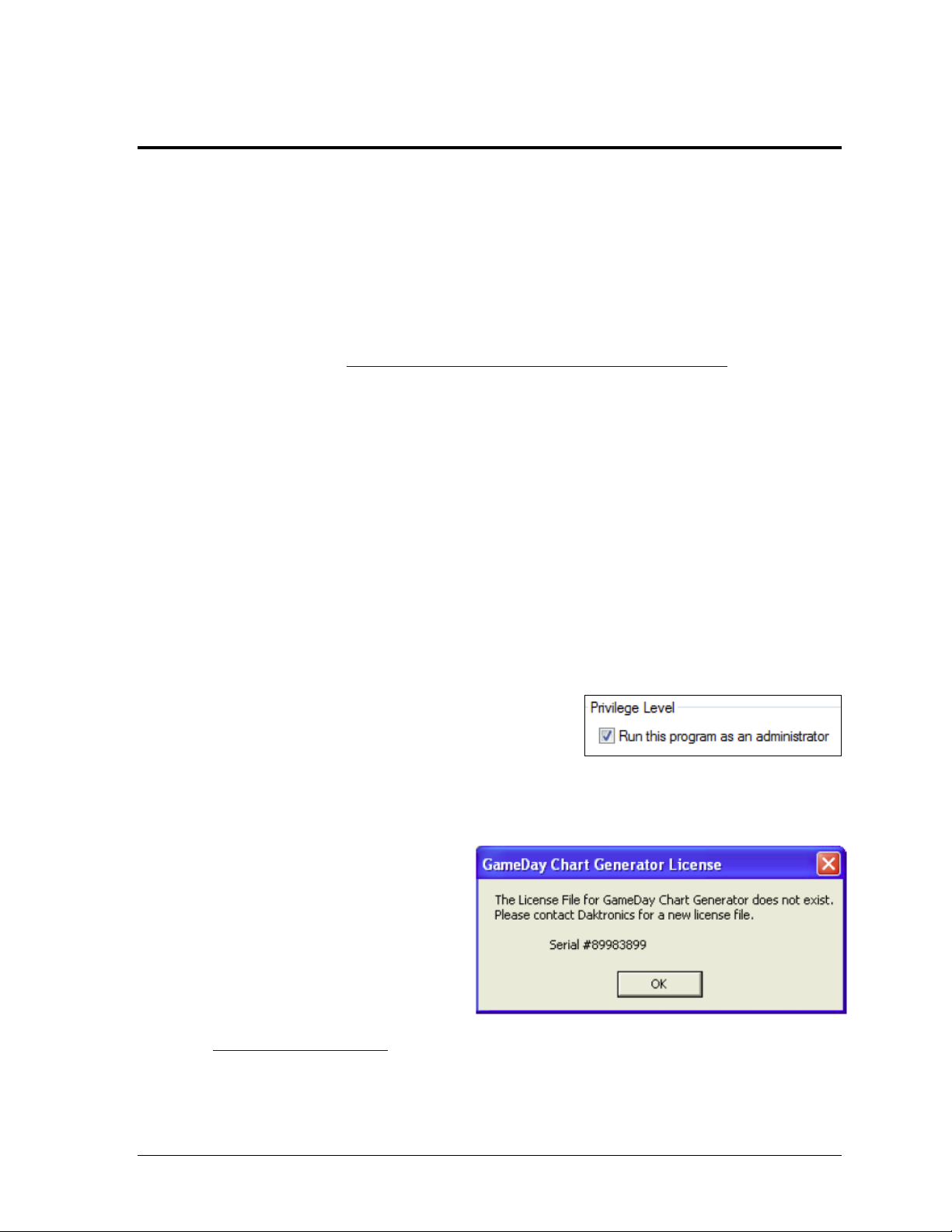
Figure 1: Run As Administrator
Figure 2: Subscription Expired
2.1 Installation
The DakStats GameDay Graphics Generator application can be downloaded from the
Internet or installed from an installation CD.
Downloading from the Internet
1. Download the DakStats GameDay Graphics Generator program.
a. Open an Internet browser.
b. Type http://dakfiles.daktronics.com/downloads/DakStats/ in the address bar.
c. Click the “GameDayGraphicsGeneratorInstall.exe” file.
d. In the window that appears, click Run. If an additional window opens, click
Run once more.
2. Follow the onscreen instructions.
3. Click Finish when done.
4. Restart the computer if prompted to do so.
5. An icon should appear on the desktop. Double-click this icon to open the program.*
Installing from the Installation CD
1. Insert the installation CD.
2. Double-click the “GameDayGraphicsGeneratorInstall.exe” file.
3. Follow the onscreen instructions.
4. Click Finish when done.
5. Restart the computer if prompted to do so.
6. An icon should appear on the desktop. Double-click this icon to open the program.*
*Note for Windows 7 users: In order to properly
open and register the program, right-click the
desktop icon and select Properties. Click on the
Compatibility tab, and under Privilege Level,
enable Run this program as an administrator (Figure 1).
2.2 Registration
A subscription is required in order to
operate the DakStats GameDay
Graphics Generator application.
The message in Figure 2 will appear
upon starting the program to inform
the user that a valid license file does
not exist. To acquire or renew a
subscription, email the Serial number
to dakstats@daktronics.com.
When the license file is emailed back, save it in
“C:\Program Files\Daktronics\GameDay Graphics Generator”
(or “C:\Program Files (x86)\Daktronics\GameDay Graphics Generator” for Windows 7).
Installation & Registration 3
Page 10

Page 11
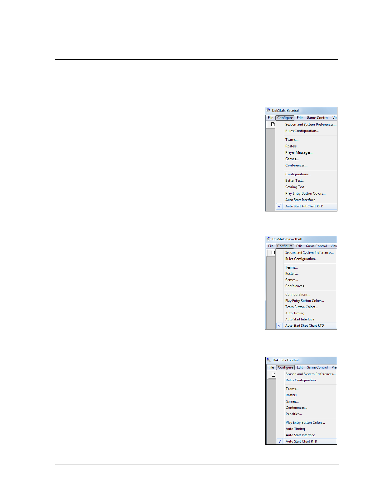
Section 3: DakStats Setup
Figure 3: DakStats Baseball
Setup
Figure 4: DakStats
Basketball Setup
Figure 5: DakStats Football
Setup
3.1 Enabling Chart RTD
Before opening the DakStats GameDay Graphics Generator application, ensure the following
settings are configured within the DakStats program being used.
DakStats Baseball
1. Go to Configure > Auto Start Hit Chart RTD (Figure 3).
2. Create or Open a competition. Refer to the Dakstats
Baseball Software Operation Manual (DD1385420) for
further instruction on opening/creating games.
3. Open the DakStats GameDay Graphics Generator
application.
DakStats Basketball
1. Go to Configure > Auto Start Shot Chart RTD
(Figure 4).
2. Create or Open a competition. Refer to the Dakstats
Basketball Software Operation Manual (ED-18169) for
further instruction on opening/creating games.
3. Open the DakStats GameDay Graphics Generator
application.
DakStats Football
1. Go to Configure > Auto Start Chart RTD (Figure 4).
2. Create or Open a competition. Refer to the Dakstats
Football Software Operation Manual (ED-18036) for
further instruction on opening/creating games.
3. Open the DakStats GameDay Graphics Generator
application.
DakStats Setup 5
Page 12

Page 13

BA LL ON - MOD E
AU TO CA LCULATE Y
Section 4: All Sport 5000 Setup
In order to use the All Sport Ball On Configuration (see Section 8.2), certain settings must be enabled
and plays must be entered in a specific way in the All Sport 5000. For more information, refer to the
All Sport 5000 Operation Manual (ED-11976), available online at www.daktronics.com/manuals.
4.1 Enabling Auto Calculate
Note: Auto Calculate must be enabled in order for the DakStats GameDay Graphics Generator
application to receive the correct ball coordinates. Auto Calculate is disabled by default.
1. Press <MENU>.
2. Use the down arrow to find the Edit Settings menu and press <ENTER> to select it.
3. Use the down arrow to find the Ball On Mode option.
4. Ensure Auto Calculate is set to on (Y), as shown below:
If Auto Calculate is set to off (N), press <ENTER>.
4.2 Play Entry
With Auto Calculate enabled, the possession, down, and distance will be entered differently
than when it is disabled. Ensure the All Sport 5000 operator knows the proper sequence to
enter this information if they are not already familiar with this mode.
Changing Possession
1. Press the appropriate <POSS> (possession) key for either the Home or Guest team.
2. Use the left or right arrow (or press <1> or <3>) to select the play direction.
3. Use the left or right arrow (or press <1> or <3>) to select the side of the field the ball
is on.
4. Use the keypad to type in the yardline the ball is on and press <ENTER>.
Changing Down & Distance
1. Press <BALL ON>.
2. Use the left or right arrow (or press <1> or <3>) to select the side of the field the ball
is on.
3. Use the keypad to type in the yardline the ball is on and press <ENTER>.
4. Use the keypad to type in the yards to go (if different from the value shown) and
press <ENTER>.
All Sport 5000 Setup 7
Page 14

Page 15

Section 5: Main Application Screen
Figure 6: Main Application Screen
Figure 7: Sport icons
The main application screen (Figure 6) is where users set up the image output configuration(s) for
each sport as well as switch between sports and monitor the graphic generating process.
5.1 Selecting a Sport
Click the appropriate icon in the lower right corner (Figure 7) to select the sport to match the
current sport in use.
Main Application Screen 9
Page 16

Figure 8: Create New
Configuration
Figure 9: New Configuration
Figure 10: Rename
Configuration
Figure 11: Delete
Configuration
Figure 12: Configure
Image Options
5.2 Creating New Configurations
Click the Create new configuration for [Sport] button to add a new
configuration to the Configurations list. In Figure 8 and Figure 9, Basketball
is shown as an example.
The Configurations list shows the configuration Name, chosen Sport, image Size/Type/Format, and
Last DakStats Update shows the last time the configuration was successfully updated from DakStats.
The colored icons underneath the H and G (Home and Guest) columns indicate the current status of
the configuration. These only apply to information coming from DakStats, not an All Sport console.
= Ready/Done
= Update pending
= Updating now
= Error occurred: This is most commonly caused by having an image destination folder that
does not exist, the files being read-only, or not having sufficient rights to update the files.
5.3 Renaming Configurations
1. Click the desired configuration to highlight it in blue.
2. Click the Rename selected configuration button
(Figure 10).
3. In the window that appears, type in a new descriptive
configuration name, and then click OK.
5.4 Deleting Configurations
1. Click the desired configuration to highlight it in blue.
2. Click the Delete selected configuration button (Figure 11).
3. In the window that appears, click Yes to confirm.
5.5 Configure Image Options
10 Main Application Screen
1. Click the desired configuration to highlight it in blue.
2. Click the Configure image options button (Figure 12).
3. The image configuration window (Figure 13) lets users
customize the following options:
Page 17

Size
Figure 13: Image Configuration
Target – sets the image dimensions in pixels.
Enter the desired image width in the first box
and the height in the second box.
Adjusted – will change automatically if needed
to avoid skewing in certain sports.
Format
Output type
Bitmap RTD (most common) – used to
send files in a format to be displayed by
the Daktronics display controller.
PDA Webcast – locks the target size to
128x128 and the image format to JPEG,
which is the best compatibility setting for
Personal Digital Assistants or websites.
Image format
Bitmap (*.bmp) – most common format
used by Daktronics display controllers.
Produces images with the largest file size.
GIF (*.gif) – usually a good option if the
charts are generated with a solid
background color. Produces images
with the smallest file size.
JPEG (*.jpg) – the best choice for most
situations. Produces images of variable size.
JPEG Quality – use the slider bar to adjust the quality of JPEG format images.
Note: The default quality of 95% produces high quality images with a reasonable
file size, while 75% produces files about half the size of 95%, but with reduced
image quality. Lower quality settings produce images with much lower
resolution for only a small improvement in file size. However, smaller files can
be generated and written faster than higher quality files. Lower this value if the
system is overloaded or slow.
Destination folders – this is where the images are saved. It is recommended to save
files to a local drive to increase performance. Network drives may be too slow.
Home – click the […] button to select the folder to save the home team images.
Guest – click the […] button to select the folder to save the guest team images.
4. Click Accept changes to save or Cancel to discard the changes.
5.6 Configure Sport Options
With a configuration selected, click the Configure Basketball options, Configure Baseball
options, or Configure Football options button to modify the desired sport settings.
Refer to Section 6 for basketball, Section 7 for baseball, or Section 8 for football.
Main Application Screen 11
Page 18

Figure 14: Ignore
Updates
Figure 15: Status Areas
5.7 Ignore Updates
Click the Ignore Updates button (Figure 14) to prevent older chart
images from being overwritten.
Note: This setting applies to all configurations for every sport!
5.8 Status Areas
The DakStats GameDay Graphics Generator application includes two status areas at the
top of the main application screen for monitoring the chart generation process (Figure 15).
These areas only apply to information coming from DakStats, not an All Sport console.
The Status area shows the chart generation (rendering) progress. This will typically display a
Ready or an Updating message. After clicking on the Ignore Updates button, this area displays
the message Updates disabled.
The Comm status area shows the communication status with the DakStats program. This will
typically display a Waiting for new data or a Receiving data message.
5.9 File Menu
The File menu includes the following options:
Save all configurations – backs up all image and sport configurations.
Load all configurations – restores all previously saved image and sport
configurations.
Note: Load all configurations cannot be undone!
5.10 Help Menu
The Help menu includes an About option for viewing program and system information.
12 Main Application Screen
Page 19

Section 6: Basketball Options
Figure 16: Basketball Options
When in Basketball mode, click on a configuration, and then click
the Configure Basketball options button to open the Basketball
options window (Figure 16). After adjusting the following settings,
click Accept changes to save or Cancel to discard the changes.
6.1 Mode
Basketball Options 13
The mode determines the appearance of the court images, either flat from above, or tilted for
a 3D effect. The image preview shows an example of how the court appears in each mode
using the default images.
Flat Half Chart
Select Flat half chart (team and/or player) to display a top-down view of half of the court.
3D Half Chart
Select 3D half chart (team and/or player) to display a tilted 3D view of half of the court.
3D Full Chart
Select 3D full chart (both teams) to display a tilted 3D view of the whole court.
Page 20

6.2 Flat Options
These options apply to both the flat half and 3D half court display modes.
Team Charts
Click Make Team charts to enable or disable shot charts for the whole team. Select whether
to only show shot charts for current half or for whole game.
Player Charts
Click Make Player charts to enable or disable shot charts for single players. Select whether to
only show shot charts for current half or for whole game.
Smoothing Options
Clicking Smooth Court Lines or Smooth Shot Images drastically improves image quality.
However, it will take longer to generate the charts. Leave these options unchecked if the
system appears to be too slow.
6.3 3D Options
Draw Shots
Select whether to show shot images for current half or for whole game. This is available only
for 3D full court images.
Court Orientation
Click the court orientation button to switch which half of the court the home and guest shots
will appear. This is available only for 3D full court images.
Oversample
Clicking Oversample (better quality) will improve the appearance of the rendered images.
However, it will take longer to generate the charts. Leave these options unchecked if the
system appears to be too slow. This is available for both 3D half and 3D full court images.
6.4 Court Image
Default Image
Select Use default image for court to leave the image as is.
Custom Image
Select Use custom image for court to specify a different court image saved on the computer.
Click the […] button to browse to the custom image file.
Custom Color
Select Use custom color for court to edit the color used for the court image. Click the dropdown arrow box to select another color and adjust the custom color values as needed.
14 Basketball Options
Page 21

6.5 Shot Images
Figure 17: Flat Half Court Shot Chart
Default Images
Select Use default shot images to leave the shot indicator images as is.
Custom Images
Select Use custom shot images to specify different shot images saved on the computer.
Click the […] button to browse to the custom image files. Select custom images for a 2-Point
Made, 2-Point Missed, 2-Point Blocked, 3-Point Made, 3-Point Missed, or 3-Point Blocked.
Note: If any fields are left blank, the default image will be used. If any filenames are
invalid, no image will be drawn.
Transparent Color
Click Apply transparent color to set the transparent color of the custom shot images.
For Daktronics display controllers, “true black” (R=0, G=0, B=0) will appear transparent.
Use the drop-down arrow boxes to select the transparent color and adjust the custom color
values as needed.
6.6 Sample Shot Charts
The sample images below are created with the default graphics available in the software.
Custom images may be used for the court as well as each shot element.
Flat Team/Individual Charts
The shot chart shown in Figure 17 shows all made/missed/blocked 2 and 3 point shots for
either one player or a whole team.
Basketball Options 15
Page 22

Figure 18: 3D Half Court Shot Chart
Figure 19: 3D Full Court Shot Chart
3D Half Team/Individual Charts
The shot chart shown in Figure 18 shows all made/missed/blocked 2 and 3 point shots for
either one player or a whole team.
3D Full Team Charts
The shot chart shown in Figure 19 shows all made/missed/blocked 2 and 3 point shots for
both teams.
16 Basketball Options
Page 23

Section 7: Baseball Options
Figure 20: Baseball Options
When in Baseball mode, click on a configuration, and then click
the Configure Baseball options button to open the Baseball
options window (Figure 20). After adjusting the following settings,
click Accept changes to save or Cancel to discard the changes.
7.1 Chart Options
Team Charts
Click Make Team charts to enable or disable hit charts for the whole team. Select whether to
only show hit charts for most recent inning or for whole game.
Player Charts
Click Make Player charts to enable or disable hit charts for single players. Select whether to
only show hit charts for most recent inning or for whole game.
Smoothing Options
Clicking Smooth field image or Smooth hit images drastically improves image quality.
However, it will take longer to generate the charts. Leave these options unchecked if the
system appears to be too slow.
Baseball Options 17
Page 24

7.2 Field Image
Default Image
Select Use default image for field to leave the image as is.
Custom Image
Select Use custom image for field to specify a different field image saved on the computer.
Click the […] button to browse to the custom image file.
Custom Color
Select Use custom color for field to edit the color used for the field image. Click the dropdown arrow box to select another color and adjust the custom color values as needed.
7.3 Ball Arcs
Draw Ball Arcs (Player charts only)
Click Draw Ball Arcs (Player charts only) to enable visual indicators of the path of safe and
out hits. Refer to Figure 22 for an example of how ball arcs appear on the hit chart.
Draw Shadows
Click Draw Shadows to apply a shadow effect below the ball arcs.
Dashed Lines
Click Use dashed lines for ground outs to apply dashed lines to ground out hits.
Safe Hit/Out Colors
Use the drop-down arrow boxes to select both a Safe Hit Color and an Out Color and adjust the
custom color values as needed.
7.4 Hit Images
Default Images
Select Use default hit images to leave the hit indicator images as is.
Custom Images
Select Use custom hit images to specify different hit images saved on the computer.
Click the […] button to browse to the custom image files. Select custom images for a Single,
Double, Triple, Home Run, Fly/Pop Out, Ground Out, Line Out, Fielder’s Choice, or Reach on Error.
Note: If any fields are left blank, the default image will be used. If any filenames are
invalid, no image will be drawn.
Transparent Color
Click Apply transparent color to set the transparent color of the custom hit images.
For Daktronics display controllers, “true black” (R=0, G=0, B=0) will appear transparent.
Use the drop-down arrow boxes to select the transparent color and adjust the custom color
values as needed.
18 Baseball Options
Page 25

7.5 Sample Hit Charts
Figure 21: Team Hit Chart
Figure 22: Individual Hit Chart
The sample images below are created with the default graphics available in the software.
Custom images may be used for the field as well as each hit element.
Team Chart
The team chart shown in Figure 21 plots the position of every safe and out hit for every
player on a specific team.
Individual Chart
The individual player chart shown in Figure 22 plots the position of every safe and out hit of
one player on a particular team. This chart uses ball arcs with shadows leading to each hit.
Baseball Options 19
Page 26

Page 27

Section 8: Football Options
Figure 23: Football Options
When in Football mode, click on a configuration, and then click the
Configure Football options button to open the Football options
window (Figure 23). After adjusting the following settings, click
Accept changes to save or Cancel to discard the changes.
8.1 Drive Chart Options
Football Options 21
Play Colors
Use the drop-down arrow boxes to select the three different colors and adjust the custom
color values for a Rush, Pass, and Penalty play as needed.
Yard Numbers
Click Enable to show yard numbers on the football field image. Select or type in a font Size in
points from “1” to “500”.
Field Options
Use the drop-down arrow box to select the field color and adjust the custom color values as
needed.
Page 28

Figure 24: Drive Chart
Figure 25: Game Overview Chart
Game Overview Chart
Click Enable to create a complete overview of all drives for both teams. Use the drop-down
arrow boxes to select the two different colors and adjust the custom color values for the Home
and Guest teams.
AllSport Ball On Configuration (Not Applicable)
Sample Drive Charts
The sample images below are shown with the default element colors and size “12” Yard
numbers enabled.
Drive Chart
The drive chart shown in Figure 24 shows all rushing, pashing, and penalty plays in the
current drive.
Game Overview Chart
The game overview chart shown in Figure 25 shows all drives made so far by both teams.
22 Football Options
Page 29

8.2 All Sport Ball On Options
Unlike the drive chart information, which comes from DakStats, ball on (down and distance)
information comes from an All Sport 5000 controller. Refer to Section 4 for more information
on setting up and operating the All Sport 5000.
Note: All Sport firmware version 4.0.2 or later is required.
In addition to an All Sport 5000 controller, the Daktronics Scoring-Timing Interface (DSTI) is
also required. This software needs a DSI configuration file that can communicate with the All
Sport. Contact Daktronics to create a new DSI file if necessary.
Play Colors (Not Applicable)
Yard Numbers (Not Applicable)
Field Options
Use the drop-down arrow box to select the field color and adjust the custom color values as
needed.
Game Overview Chart (Not Applicable)
AllSport Ball On Configuration
Click Enable to begin selecting the settings for this type of chart.
Center Ball On Image
Check this option to center the ball on image on the current yardline. If unchecked, the ball
on image always will be behind the current yardline.
Field Orientation
Select a Vertical or Horizontal orientation for the field. Note that when switching between
these options, it is likely that the image size dimensions (width and height) will also have to
be switched. Refer to Section 5.5.
Direction of Travel
The text of these options will vary depending on the Field Orientation:
Normal (via AllSport): Displays the ball based on the settings in the All Sport
Always Home On Top/Left: Home end zone will always be on the top or left
Always Home On Bottom/Right: Home end zone will always be on the bottom or right
Always Top to Bottom/Left to Right: Direction of play will always move from the
top to the bottom or from the left to the right
Always Bottom to Top/Right to Left: Direction of play will always move from the
bottom to the top or from the right to the left
Football Options 23
Page 30

Figure 26: 560x32 Chart #2
Figure 27: 560x32 Chart #1
CE NTER FI EL D -SET
YA RDS 5 0 *
Field Size (Yards)
If using the default of “100” yards, nothing must be changed. If using a different number of
yards, this value must be twice what is shown for the Center Field value in the All Sport:
1. Press <MENU>.
2. Use the down arrow to find the Edit Settings menu and press <ENTER> to select it.
3. Use the down arrow to find the Center Field-Set Yards option.
4. Use the keypad to type in the center field yardline if needed, and press <ENTER>.
End Zone Size (Yards)
Enter the size of the end zone in yards.
Home & Guest Team Images
Click the […] button to browse to the custom image files. Select custom images for the
End Zone Image, 1st Down Ball On, 2nd Down Ball On, 3rd Down Ball On, or 4th Down Ball On
for both the Home and Guest Team.
Note: If any fields are left blank, the default image will be used. If any filenames are
invalid, no image will be drawn.
Under Home/Guest Image Position, select Center to use the full-size home/guest images or Fit
to stretch or shrink the images to the width of the field.
Background
Check Use Image to enable the use of a custom background image. Click the […] button to
browse to the custom image file. Note that if there is no background image, the Field options
Color determines how the field will appear.
Under Background Image Position, select Center to use the full-size background image or Fit to
stretch or shrink the image to the width of the field.
To-Go Image
Click the […] button to browse to the custom image file.
Sample Ball On Charts
The sample images below are shown with Center Ball On Image enabled and the Image Home
Position set to Fit.
The image shown in Figure 27 has the default ball on image and background color.
The image shown in Figure 26 has the default ball on image along with a custom background
image and a custom to go image.
24 Football Options
Page 31

Section 9: Displaying Image RTD
RTD Field Name
Field#
Item#
Length
Field Type
HOME TEAM NAME
90
604
20
BMP RTD
GUEST TEAM NAME
439
1965
20
BMP RTD
BATTER BITMAP SPRAY CHART
785
3315
10
BMP RTD
RTD Field Name
Field#
Item#
Length
Field Type
Any player Number and Name fields
next to each other
(multiple)
(multiple)
14
BMP RTD
Home Data – Team name
161
521
20
BMP RTD
Guest Data – Team name
202
678
20
BMP RTD
RTD Field Name
Field#
Item#
Length
Field Type
CURRENT DRIVE – BITMAP RTD FIELD
539
3398
15
BMP RTD
RTD Field Name
Field#
Item#
Length
Field Type
BALLON
84
340 6 BMP RTD
The following sections list the proper Input Template Files (ITFs) needed to display the images
generated by the software for each sport.
9.1 Baseball
Input Template File: “DSTI DSBA Scoreboard.itf”
9.2 Basketball
Input Template File: “dsbb sbrd.itf”
Note: If player headshots are using the same naming format (“##Player”), they will have
to be renamed in order to use the shot charts. Try using either the number or name only.
9.3 Football
Drive Charts
Input Template File: “dsfb sbrd.itf”
Ball On Charts
Input Template File: “AS5-Football.itf”
Displaying Image RTD 25
Page 32

Page 33

Section 10: Troubleshooting
Problem
Solution
The icon in the main application
window is red and the images are
not being refreshed.
Check the image destination folder to make
sure it exists (see Section 5.5).
If the directory exists, make sure the user has
the necessary read/write permissions.
The files are not updating.
Check to see if the DakStats software is running
and if RTD is enabled (see Section 3.1).
Check to make sure the TCP/IP protocol is
installed on the DakStats GameDay Graphics
Generator computer and the DakStats
computer.
If using an All Sport 5000 console, ensure it is
properly connected to the DSTI computer and
using the appropriate settings (see Section 4).
Below is a list of possible situations that may occur while operating the software. With each situation
is a solution to the problem as well as a reference to another section of this manual that may assist
with the problem.
Troubleshooting 27
Page 34

Page 35

Section 11: Contact Information
Mail: Daktronics, Inc., Customer Service
201 Daktronics Drive
P.O. Box 5128
Brookings, SD 57006
Phone: DakStats Help Desk: 1-888-325-7828
DakStats Fax: 1-605-697-4700 Attn: DakStats
Email: dakstats@daktronics.com
If there are any questions about installing, registering, or operating the DakStats GameDay Graphics
Generator program that are not covered in this manual, please contact DakStats Customer Service:
Contact Information 29
 Loading...