

Page 1

Galaxy® AF-3500/3550
Installation and Operation Manual
DD1377306 Rev 16—10 July 2014
201 Daktronics Drive PO Box 5128 Brookings, SD 57006
tel 800-843-5843 fax 605-697-4700
www.daktronics.com
Page 2
DD1377306
Product 1472, 1473, 1569
Rev 16—10 July 2014
Complete the chart with specific information about this display so the details are readily available when calling for
service or replacement parts.
Information needed for technicians and/or Customer Service Fill in the blank
Location address of the display:
Model number of the display:
Version of software being used:
Method of communication being used:
Controller version used in the display:
Copyright © 2008-2014
All rights reserved. While every precaution has been taken in the preparation of this manual, the publisher assumes no
responsibility for errors or omissions. No part of this book covered by the copyrights hereon may be reproduced or copied in any
form or by any means – graphic, electronic, or mechanical, including photocopying, taping, or information storage and retrieval
systems – without written permission of the publisher.
Galaxy® and Venus® are trademarks of Daktronics, Inc. Windows® is a trademark of Microsoft® Corporation. IBM® is a trademark of IBM Corporation. Mate-N-
Lok® is a trademark of AMP Company.
Page 3

Table of Contents
Section 1: Overview of the Displays .................................................................................................................... 1
1.1 Display Details ...................................................................................................................................................... 1
Section 2: Mechanical Installation ....................................................................................................................... 3
2.1 Pre-Installation Checklist .................................................................................................................................... 3
2.2 Support Structure Requirements ....................................................................................................................... 3
2.3 Display Mounting ................................................................................................................................................ 4
General Mounting Procedure ...................................................................................................................... 4
Section 3: Power Installation ................................................................................................................................ 5
3.1 Conduit .................................................................................................................................................................. 5
3.2 Overview of Power/Signal Connection ........................................................................................................... 5
3.3 Power Requirements ............................................................................................................................................ 6
Main Disconnect ............................................................................................................................................ 6
3.4 Power Grounding ................................................................................................................................................. 6
3.5 Display Grounding .............................................................................................................................................. 6
Important Points About Grounding........................................................................................................... 6
3.6 Power Connection ................................................................................................................................................ 7
For Displays With an External Power Termination J-box ....................................................................... 7
For Displays With Internal Power Termination ....................................................................................... 8
3.7 Power Routing in the Display ............................................................................................................................ 8
Section 4: Signal Installation Overview ..............................................................................................................11
4.1 Primary/Mirror Display Interconnections ..................................................................................................... 11
4.2 USB to Ethernet Adapter ................................................................................................................................... 11
4.3 Setting the IP Address on the Display Controller ......................................................................................... 11
Section 5: Start-Up Procedure ........................................................................................................................... 15
5.1 Start-Up Checklist .............................................................................................................................................. 15
5.2 Start-Up Sequence .............................................................................................................................................. 15
5.3 Post Installation Checklist ................................................................................................................................. 15
Section 6: Maintenance ...................................................................................................................................... 17
6.1 Proper Ladder Use ............................................................................................................................................. 17
6.2 Internal Display Access ..................................................................................................................................... 17
6.3 Ventilation System/Fans .................................................................................................................................. 18
Frequency of Inspection ............................................................................................................................. 18
Fan Blades .................................................................................................................................................... 18
Filters ............................................................................................................................................................ 18
Fan Test ......................................................................................................................................................... 19
6.4 Display Face Cleaning ....................................................................................................................................... 19
Table of Contents i
Page 4

Dry Cleaning Process ................................................................................................................................. 20
6.5 Annual Inspection .............................................................................................................................................. 20
Section 7: Diagnostics and Troubleshooting .................................................................................................... 21
7.1 Controller Diagnostics ....................................................................................................................................... 21
7.2 MLC Diagnostics ................................................................................................................................................ 21
7.3 Troubleshooting Display Problems ................................................................................................................ 22
Common Misconceptions .......................................................................................................................... 22
Module and LED Problems ....................................................................................................................... 22
Brightness Problems ................................................................................................................................... 23
Message Problems ....................................................................................................................................... 23
Temperature Problems ............................................................................................................................... 24
Temperature Problems ............................................................................................................................... 24
Testing Displays .......................................................................................................................................... 24
Before Calling For Help ............................................................................................................................. 24
Section 8: Parts Replacement ............................................................................................................................ 25
8.1 About Replacement Parts .................................................................................................................................. 25
8.2 Instructions for Replacing Parts ....................................................................................................................... 25
Controller Replacement ............................................................................................................................. 26
Controller Address Setting ........................................................................................................................ 27
MLC Replacement ....................................................................................................................................... 27
Power Supply Replacement ...................................................................................................................... 28
Light Sensor Replacement ........................................................................................................................ 28
Temperature Sensor Replacement ............................................................................................................ 29
Section 9: Daktronics Exchange and Repair & Return Programs .................................................................. 31
9.2 Repair & Return Program ................................................................................................................................. 32
Shipping Address........................................................................................................................................ 32
9.3 Daktronics Warranty and Limitation of Liability .......................................................................................... 32
Appendix A: Reference Drawings .......................................................................................................................... 35
Appendix B: Temperature Sensor Installation (DD2638167) ............................................................................... 37
Appendix C: International Installation ................................................................................................................... 39
Appendix D: Maintenance Log ............................................................................................................................... 41
Appendix E: Daktronics Warranty and Limitation of Liability (SL-02374) .......................................................... 43
ii Table of Contents
Page 5
Section 1: Overview of the Displays
Note: This manual provides installation, maintenance, and troubleshooting information to help ensure the optimal
performance of Daktronics Galaxy® AF-35XX displays. Diagnostic information and parts replacement are also
included and a “Glossary” is found near the end of this manual.
1.1 Display Details
The Galaxy® model numbers are described as follows:
AF-35XX-RRxCCC-MM-R,A,RGB-XX
AF-35XX = Outdoor Galaxy display
RR = Number of pixel rows high
CCC = Number of pixel columns long
MM = Pixel pitch in millimeters
R, A, RGB =
XX = SF (Primary) or 2V (Primary/Mirror)
Displays are either single-face or 2V (Two View) units. In 2V units, the first display is referred to as primary.
The second display is called the mirror.
LED Color: R (Red), A (Amber),
RGB (Full Color – Red, Green, Blue)
A typical display system is controlled with a Windows®-based computer running Venus® 1500 software.
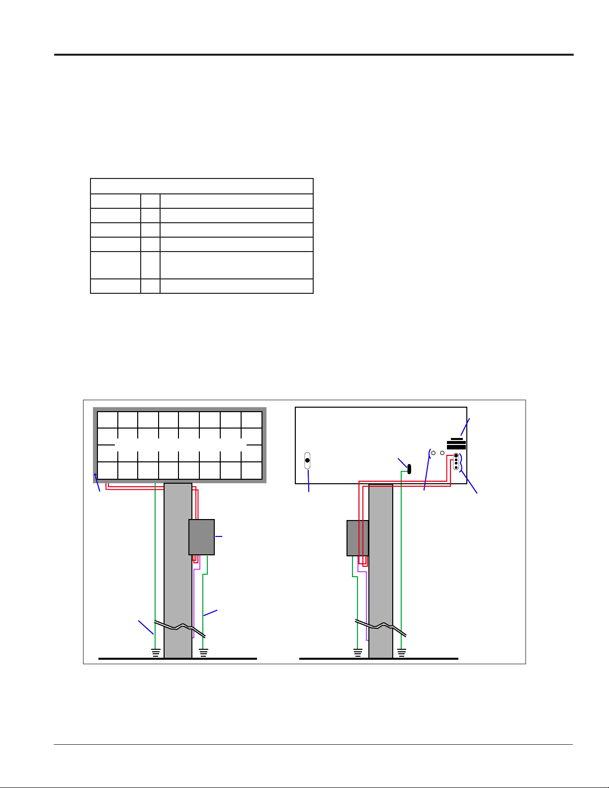
Figure 1 shows front and back views of a typical display.
Label(s)
Quick
Connect
Inputs
Primary Display – Front View
Blue Dot
Grounding
Electrode
Conductor
Signal
Termination
Enclosure
Signal Enclosure
Ground Electrode
Conductor
(When Required)
Primary Display – Rear View
Ground Lug
Connect
Output
to Mirror
Display
Optional
Conduit
Drilling
Guides
(Etched)
Figure 1: Display Components
Overview of the Displays 1
Page 6

Page 7

Section 2: Mechanical Installation
Read the Mechanical, Power and Signal Installation sections before installing the display(s).
Daktronics’ engineering staff must approve any changes that affect the weather-tightness of the display. Prior to
making any modifications, detailed drawings of the changes must be submitted to Daktronics for evaluation and
approval, or the warranty will be null and void.
Daktronics is not responsible for installations or the structural integrity of support structures done by others. The
customer must ensure a qualified structural engineer approves the structure and any additional hardware.
2.1 Pre-Installation Checklist
Verify the following before installation:
• The display is in good condition after shipping and uncrating.
• A straight and square mounting frame is provided for the display.
• Height variation in any 4' (1.2 m) horizontal section must not exceed 1/4" (6.3 mm).
• Adequate support is provided for the display so that the structure will not yield at any unsupported
points after mounting.
• Leave 4" (10.2 cm) of unobstructed space above the display so the eyebolts can be removed. No clearance
is required once the eyebolts are removed.
• Maintain clearance around the display to allow unobstructed air flow through the vents and fans and to
allow access to internal components.
• Assure the display cabinet has no holes (accidental or intentional) that could allow water to enter the
display.
• Check that all display modules are fully latched into the display cabinet.
2.2 Support Structure Requirements
The installer must ensure that the mounting structure and hardware can support the display, and that the
structure follows all local codes.
Support structure design depends on the mounting methods, display size, and weight. Because every
installation site is unique, no single procedure is approved by Daktronics for mounting Galaxy® displays.
The information contained in this section is general information only and may not be appropriate for all
installations. Refer to Figure 2 for basic display set ups.
Mounting plans need to take into account the ventilation system and face-mounted light sensor. In general,
the entire front of all displays must be completely unobstructed to allow for air flow and internal access.
Displays contain fans that pull air in from the lower vents and exhaust it out adjacent vents.
Mechanical Installation 3
Page 8
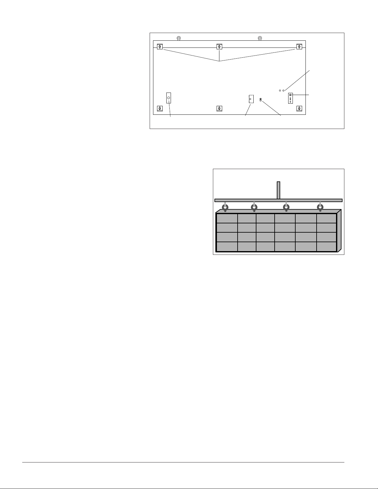
Also, keep in mind the location of mounting clips and the clearance needed for the power and signal
terminations on the back of the
display shown in Figure 2. Display
height and wind loading are also
critical factors to consider. Consult
the Shop Drawing, which is included
with the display.
2.3 Display Mounting
To maintain the structural integrity
of the display cabinet, keep a
90-degree angle between the cabinet
and the lifting method.
If damage occurs because of
improper lifting procedures, the warranty will be void.
Mounting Clips
Back of Display
Quick Connect
Signal Out
Figure 2: Back View of Typical Display
External Junction Box
For Power Termination
Ground Lug for Ground
Rod Connection
Optional
Signal
Entrance
Quick Connect
Signal Input
General Mounting Procedure
Use Lift Bar and ALL Eyebolts
1. Lift the display into position on the support structure,
following the example in Figure 3.
Note: Do not attempt to permanently support the
display by the eyebolts.
2. Weld or use 1/2" grade-5 (or stronger) bolts and
hardware to secure ALL of the clip angles to the support
structure as shown in the Shop Drawing which is
included with the display.
Note: Alternative mounting methods are acceptable as
long as all bolt locations are used.
Figure 3: Correct Lifting
3. Refer to Section 3 for power routing and to the appropriate communication manual for signal
connections to the display.
4. After installation is complete, carefully inspect the display for any holes that may allow water to seep into
the display and seal any openings with silicone.
If the eyebolts on the top of the display were removed, plug the holes with bolts and the rubber-sealing
washer that was removed with the eyebolt unless an overhead structure protects the area.
4 Mechanical Installation
Page 9

Section 3: Power Installation
Only a qualified individual should terminate power and signal cable at this Daktronics display.
All proposed changes must be approved by Daktronics’ engineering staff or the warranty will be null and void.
3.1 Conduit
Daktronics does not provide conduit. Separate conduit must be used to route:
• Power
• Signal IN wires to the signal termination enclosure (when applicable).
• Signal OUT wires (if not using the provided interconnect cable).
For power, displays have either a J-box or a 3/4" conduit access hole located near the lower right on the back
of the display. For signal, displays have signal input quick connects or etched drilling guides for conduit.
3.2 Overview of Power/Signal Connection
1. Power to the display is terminated externally in most cases. Section 3.6 shows external wiring examples.
2. Possible methods for signal termination are shown in the various communication manuals.
3. Power is routed to the display through a fused disconnect switch capable of opening all ungrounded
power conductors. Install the disconnect within the line of sight of any personnel performing
maintenance on the display, unless it can be locked in the open position.
Note: Displays are equipped with circuit breakers that carry a UL489 or UL1077 (IEC 60947, VDE 660) rating.
These devices are intended only to protect the components within the display.
4. Route power conductors from the disconnect to the display through conduit following local code
specifications.
5. Display power terminates either to the J-box or internally at the power termination panel.
6. Connect the grounding conductor to the grounding lug on the back of the display.
7. Route signal cable to the signal termination enclosure. Ground the enclosure to an isolated earth-ground
connector (when required).
8. Route signal into the enclosure through conduit. The knockouts on the enclosure require the use of 3/4"
conduit.
9. Route signal quick-connect cables from the enclosure to the display either through conduit or through the
display pole if power is not also routed in the display pole.
Note: Daktronics strongly recommends that the quick-connect cables be secured to protect them from
weather or vandalism.
Mechanical Installation 5
Page 10
3.3 Power Requirements
Install this display according to all applicable local and national electrical codes. This includes proper
grounding and bonding of the display.
Do not connect the display to any voltage other than that listed on the Daktronics product label.
Displays use single-phase power. Proper power installation is imperative for display operation. Find power
specifications on drawings shipped with the display.
Important Notes:
• Daktronics recommends that a separate circuit be run to the electronic display(s) to isolate it and
prevent any issues that could be caused by line voltage fluctuations or high frequency noise on the
power line caused by other types of equipment. A separate circuit also makes display maintenance and
troubleshooting easier. Daktronics assumes no liability for any issues caused by line voltage fluctuations
or other improper power conditions if these recommendations are not followed.
• Size conductors of circuits that deliver power to the display according to national and local electrical
codes so the power distribution system delivers full-load power to the display while maintaining a
voltage within 5 percent of the utility nominal voltage.
Main Disconnect
Daktronics requires using a power disconnect switch with the display. Use a disconnect so that all
ungrounded conductors can be disconnected near the point of power connection.
Locate the disconnecting means either in a direct line of sight from the display or so it can be locked in the
open position. This ensures that power is not reconnected while service personnel work on the display.
3.4 Power Grounding
Ground displays according to the provisions
outlined in local and national electrical codes.
Install these displays using the provided ground
and neutral conductors. The power cable must
contain an isolated earth-ground conductor.
Do not connect neutral to ground at the disconnect
or at the display. This violates electrical codes and
voids the warranty.
3.5 Display Grounding
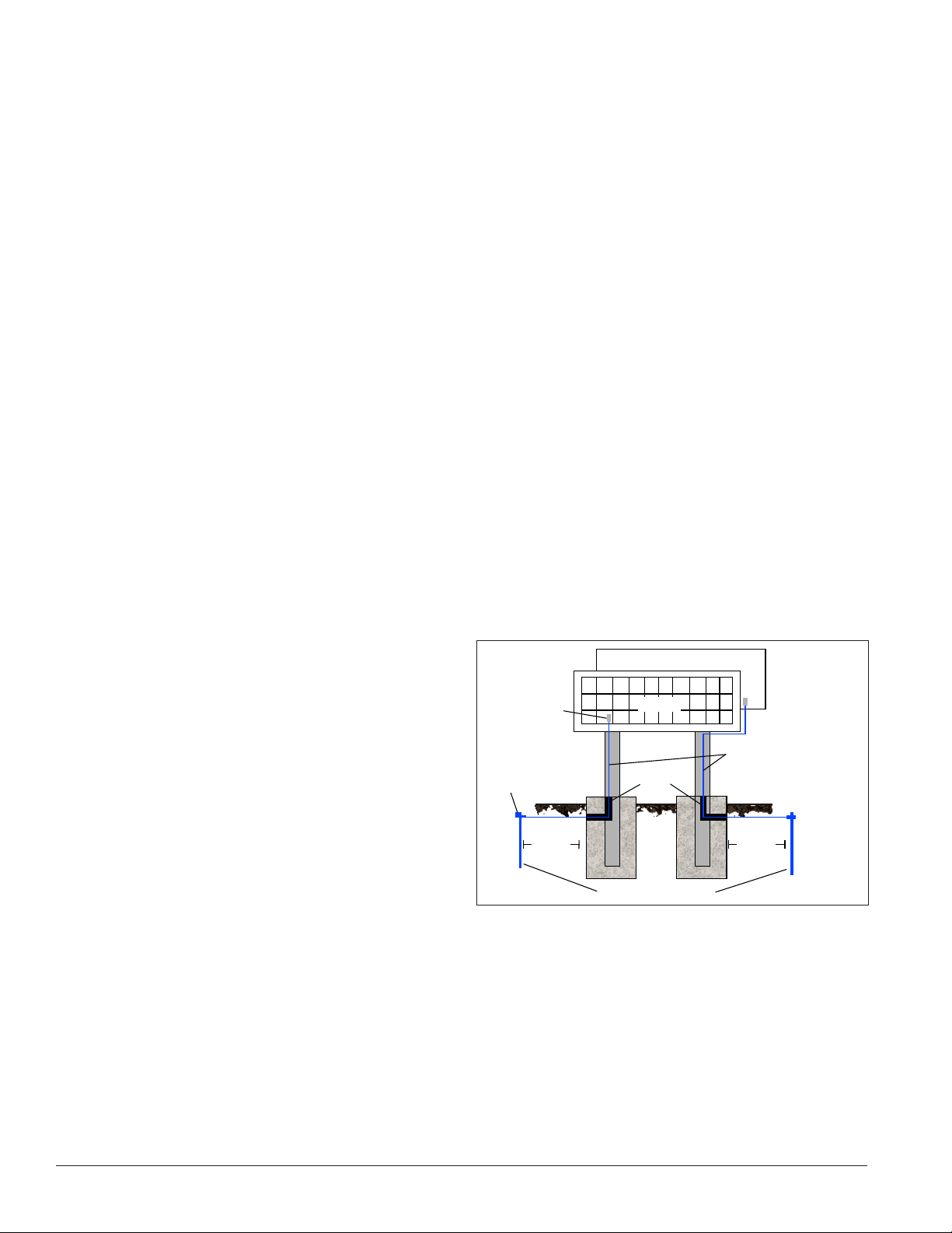
Connect the display system to earth ground as
shown in Figure 4. Proper grounding protects the equipment from damaging electrical disturbances and
lightning. The display must be properly grounded or the warranty will be void.
Display
Ground Lug
Thermal Weld
Connection
Preferred
8 ft.(2.5 m)
min.
Figure 4: Correct Grounding
Primary
Conduit
Copper Ground Rods
Mirror
Copper Ground Conductor
(One Per Display Face)
8 ft.(2.5 m)
min.
Important Points About Grounding
• Resistance to ground 10 ohms or less: This is required by Daktronics for proper display performance.
If the resistance to ground is higher than 10 ohms, install additional grounding electrodes to reduce the
resistance. The grounding electrode should be installed within 25' (7.6 m) of the base of the display and
must be connected to the ground lug on the back of the display. Refer to Figure 4.
6 Power Installation
Page 11
• Follow local and national codes: The material of an earth-ground electrode differs from region to region
and for conditions present at the site. Consult any local and national electrical codes that may apply.
• Support structure cannot be used as an earth-ground electrode: Daktronics does not recommend using
the support structure as an earth-ground electrode; concrete, primer, corrosion, and other factors make
the support structure a poor ground.
Note: The support structure may be used as an earth-ground electrode only if designed to do so. A qualified
inspector must approve the support structure and grounding methods.
• One grounding electrode for each display face: The grounding electrode is typically one grounding rod
for each display face. Other grounding electrodes as described in any local and national electrical codes
may be used.
3.6 Power Connection
Power is most often terminated externally to the J-box on displays. However, larger displays require power to
be terminated internally in the Power Termination Panel.
For Displays With an External Power Termination J-box
Terminating hot, neutral, and ground wires at the J-box:
1. Route the power cable through conduit to the rear of
the display and into the power termination J-box (the
J-box contains 3/4" threaded conduit fittings).
2. The J-box contains two or three wires plus a ground
coming from the interior of the display. These wires
are pre-terminated to the power termination panel
inside the display.
3. Inside the external J-box, connect the power wires to
the wires coming from the display interior using wire
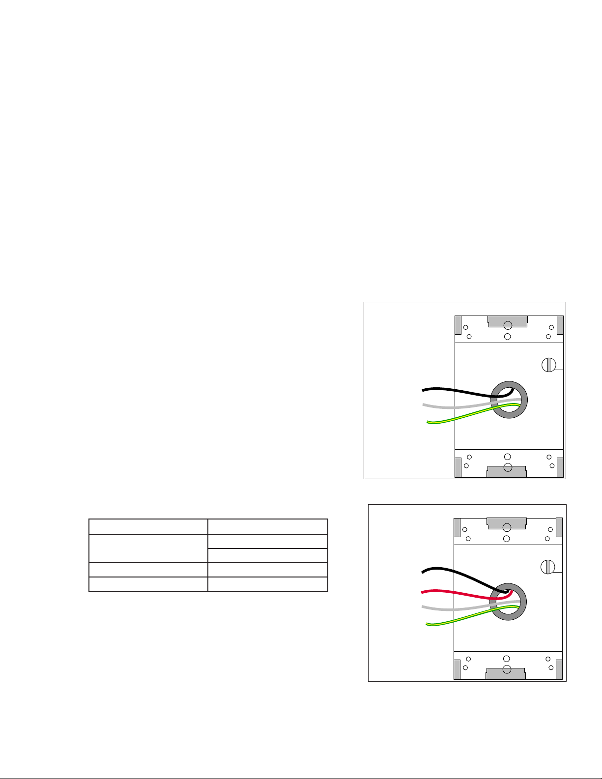
nuts. Refer to Figure 5 for 120 VAC and Figure 6 for
120/240 VAC.
Note: The following colors are used for the pre-terminated
wires:
120 VAC 120/240 VAC
• Line 1 – Black
• Neutral – White • Neutral – White
• Ground – Green/Yellow • Ground – Green/Yellow
• Line 1 – Black
• Line 2 – Red
120 V Termination
(Box with Cover Removed)
Line 1 – Black
Neutral – White
Ground – Green/Yellow
Wiring from power termination
panel inside display
Figure 5: 120 V J-box Termination
120/240 VAC Termination
(Box with Cover Removed)
Line 1 – Black
Line 2 – Red
Neutral – White
Ground –
Green/Yellow
Wiring from power termination
panel inside display
Figure 6: 120/240 V J-box Termination
Power Installation 7
Page 12
For Displays With Internal Power Termination
15
15
15
15
15
15
GRN
WHT
BLK
GRN
Z1 Z2
Z3
Z4 Z5 Z6
LINE 1
NEUT.
E41
LINE 2
GROUND
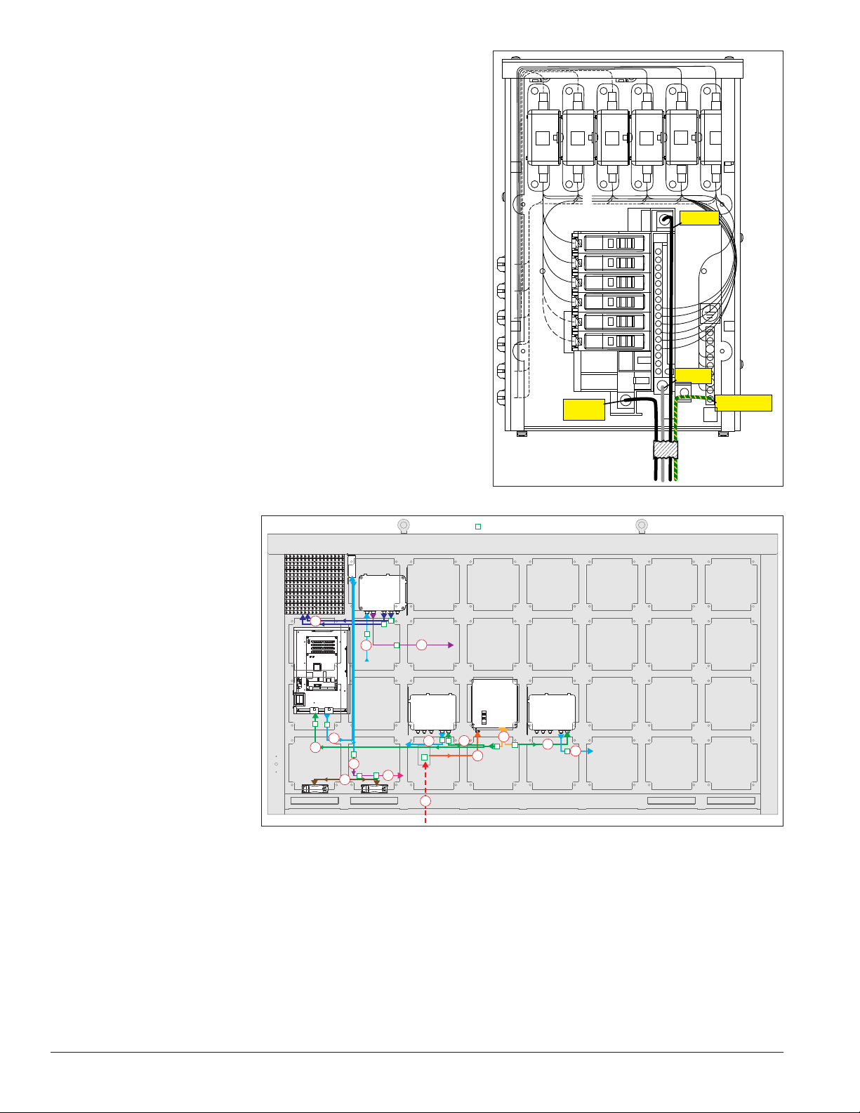
Terminating single-phase power to the internal power
termination panel:
1. Open the display as explained in Section 6 and locate
the power termination panel.
2. Route the cable through conduit to the back of the
display. Use the 3/4” knockout for access, being
careful not to damage internal components.
3. Connect the neutral wire to the neutral lug and the
live wires to the Line 1 and Line 2 lugs.
4. The ground wire connects to the grounding bus bar.
Refer to Figure 7 for an example.
3.7 Power Routing in the Display
The following list corresponds to the numbers and letters in
Figure 8.
1. Power enters the display from an external power
source, either through a rear-mounted J-box, or
directly through a cabinet knockout.
2. Power then
enters the
internal circuit
breaker box.
Figure 7: Single-phase 6-breaker Domestic Panel
= Electrical Connector
3. Power leaves
the circuit
breaker box
through wiring
5c
5b
6b
harnesses
including a Y
harness that
4. a. Power travels
sends power
to multiple
components.
into the display
5a
4a
6a
7a
5b
8a
1
3
4b
2
4b
5b
controller
enclosure.
b. Power travels
to power supplies.
5. a. Power leaves the display controller enclosure and travels to the thermostat.
b. Power leaves the power supply and travels to the following power supply.
c. Low voltage power leaves the power supply and travels to the display module.
One module per power supply connects to the voltage adjust cable.
Figure 8: Power Flow Summary
8 Power Installation
Page 13

6. a. Power leaves the thermostat and travels through a tapped wiring harness.
b. Power leaves this power supply and travels to the next power supply.
7. a. The ventilation fans receive power from the tapped wiring harnesses.
Power Installation 9
Page 14

Page 15
Section 4: Signal Installation Overview
For specific details on installing the communications, consult the quick guide and manual included with the
communication equipment. Each type of communication is listed below with its manual number.
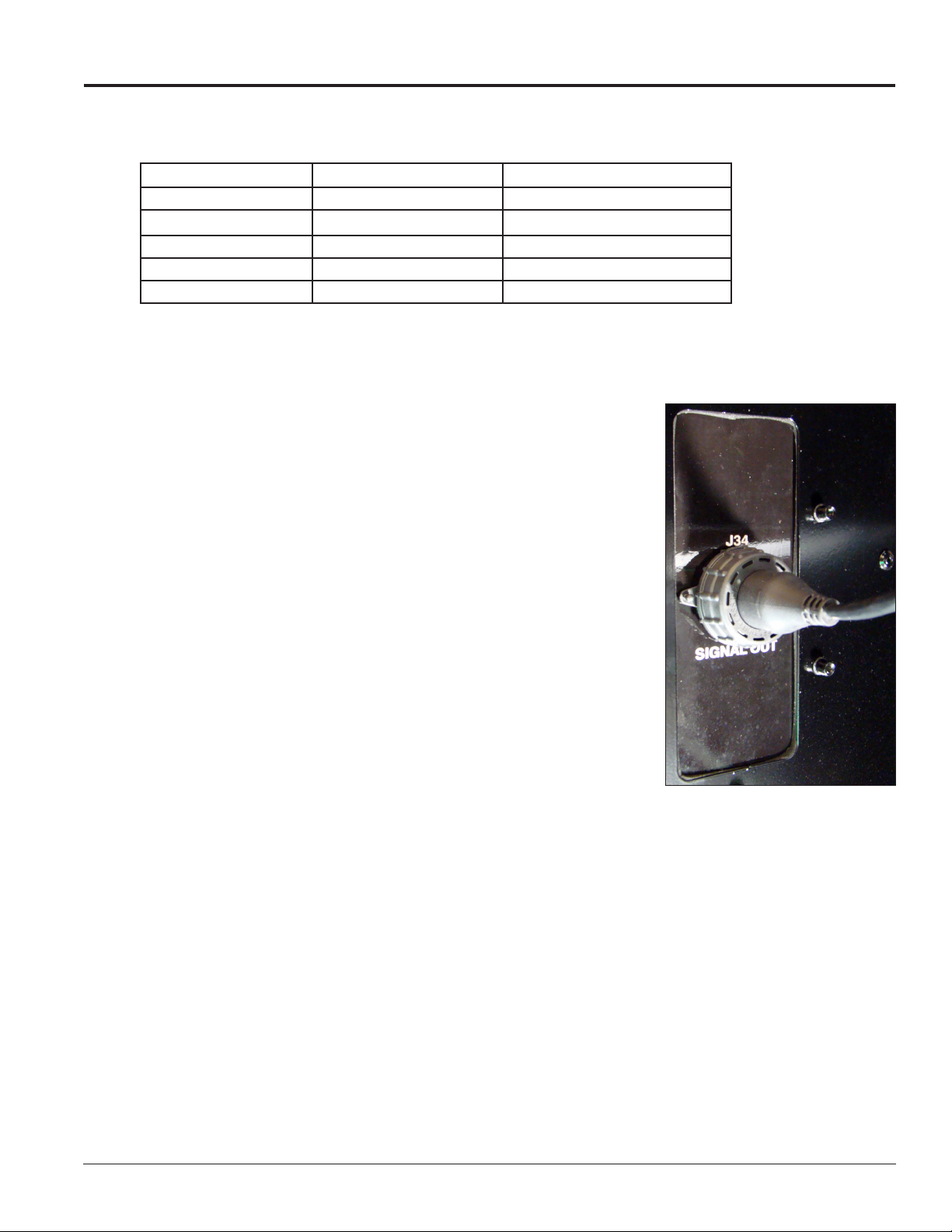
Communication Type Communication Manual Communication Quick Guide
Wireless Ethernet Bridge DD1685027 DD1417586
Ethernet DD1417609 DD1417573
Fiber Ethernet DD1417611 DD1417581
WiFi DD1417619 DD1417592
USB to Ethernet Adapter N/A DD1790707
Note: These are the standard communication types but each site is unique and may include additional equipment. If
problems arise, contact the display’s service company or Daktronics Customer Service.
4.1 Primary/Mirror Display Interconnections
If this display is a two-sided primary/mirror display, a quick-connect cable
is provided to connect the signal between the two faces. Refer to Figure 9
for an example. Secure the excess cable to the support structure to prevent
damage from weather or vandalism.
4.2 USB to Ethernet Adapter
A USB to Ethernet adapter is included with the display and can be used
to bypass network configuration in situations where simple point-to-point
communication is required. The adapter creates a secondary network that
is dedicated to communication with the display, but network operation is
still enabled through the primary network.
The USB to Ethernet Adapter can be used in conjunction with
communication kits supplied with the display. Refer to DD1790707 for
more information regarding the adapter.
4.3 Setting the IP Address on the Display Controller
Galaxy AF-35XX display controllers are set to the default IP address
172.16.192.25 prior to shipping. This address can be changed to an address specific to the local display
network. Obtain an appropriate IP address for the display from the network administrator.
The display must have power and M2Config installed on the computer to complete the following steps.
Download M2Config at: dakles.daktronics.com/downloads/venus1500/utils/M2_Cong
Communication with the display controller is necessary and can be done through the purchased
communication method or directly to the display controller using a Cat5 cable.
Figure 9: Primary/Mirror Quickconnect Cable
Display power must be On to complete this configuration.
1. Set the computer’s IP address to 172.16.192.20 and the SubnetMask to 255.255.0.0.
2. Open M2Config:
Signal Installation Overview 11
Page 16
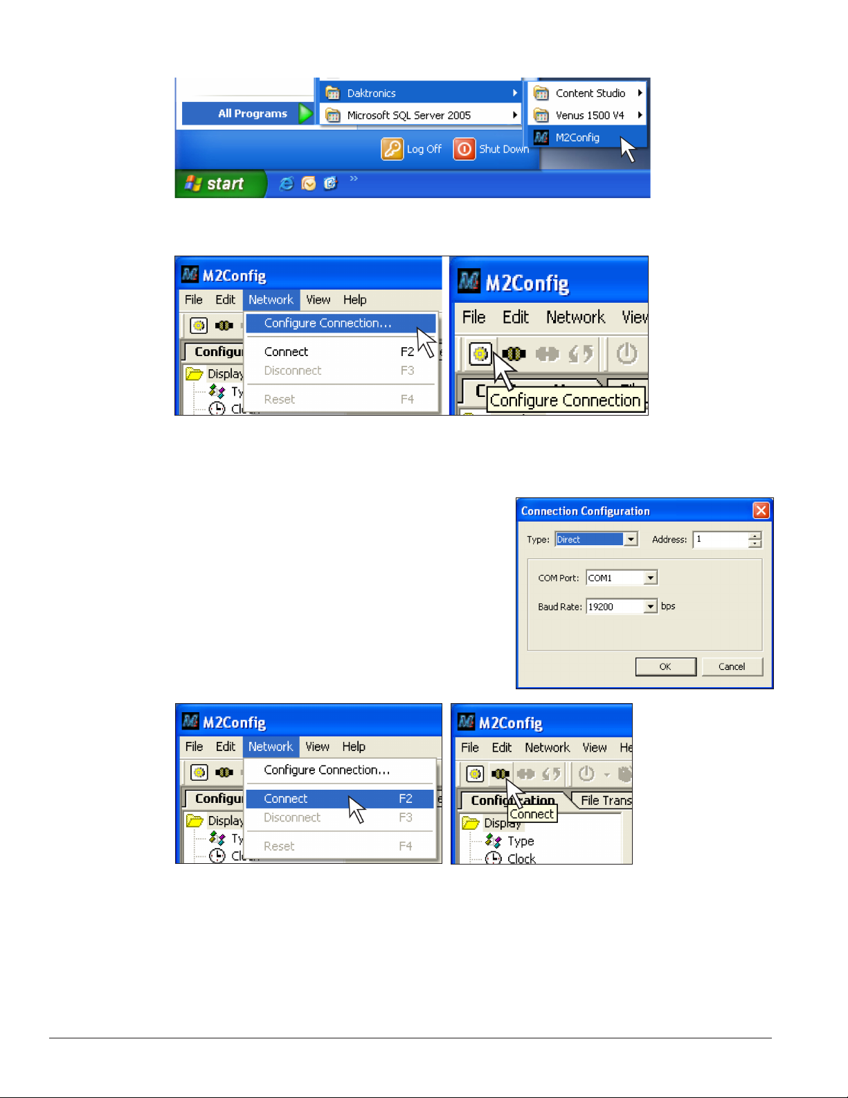
• Click Start>AllPrograms>Daktronics>M2Cong or double-click the shortcut on the desktop.
3. Configure the communication method to connect to the display by choosing Network, then
CongureConnection or click the CongureConnection icon.
4. The M2 Configuration Studio has two folders under the Configuration tab:
Click the Communications folder.
5. Choose the following for your display to configure a direct
connection:
• Type: TCP/IP
• Address: 1 (refer to address dials on controller for
actual setting)
• IP Address: 172.16.192.25
6. Choose Network and Connect or click the Connect icon to
connect to the display.
12 Signal Installation Overview
Page 17
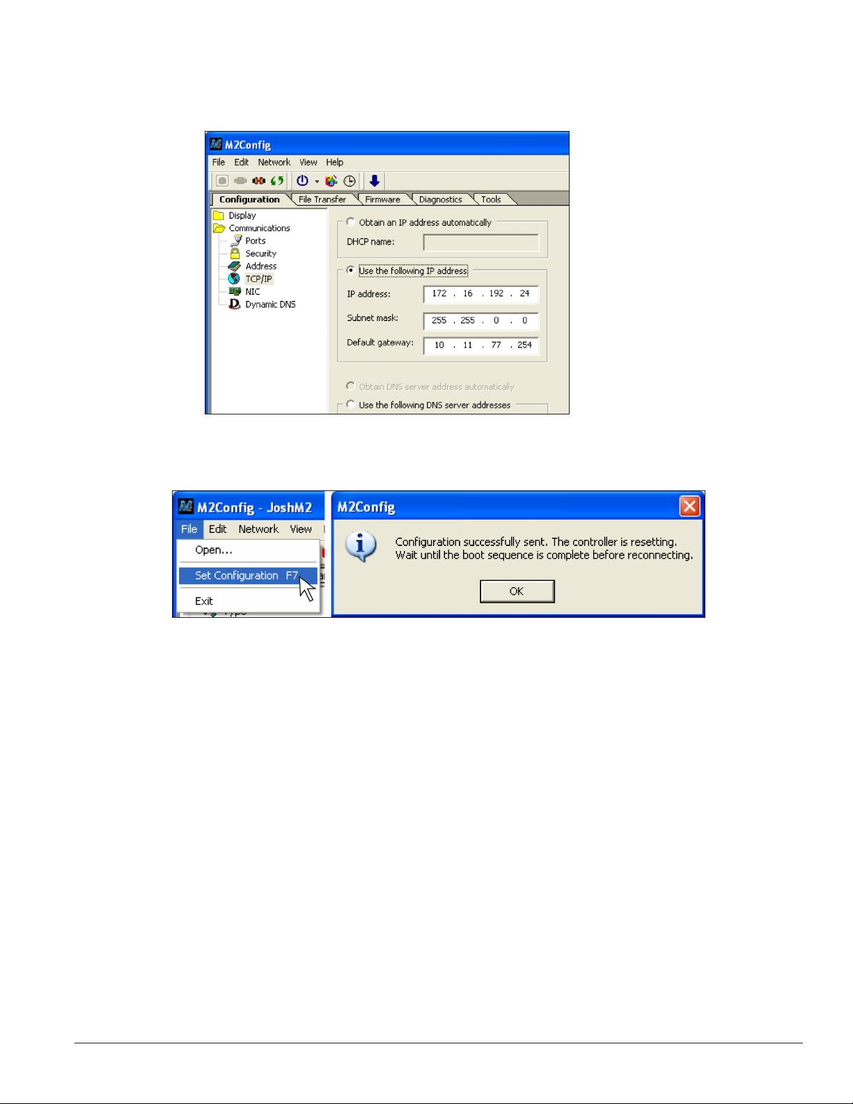
7. After connecting to the controller, select the Communications folder on the left side of the screen and
select TCP/IP:
• Input the IP address, Subnet mask and Gateway as provided by the Network Administrator.
8. Choose File>SetConguration to upload the new IP address to the display.
9. When the warning appears, click OK and wait for display to reboot.
10. Close M2Config.
For further information on using a TCP/IP network with the display, refer to the Venus 1500 software help
file.
Signal Installation Overview 13
Page 18

Page 19
Section 5: Start-Up Procedure
Before starting up the display, review this checklist to ensure that all parts are ready to operate correctly.
5.1 Start-Up Checklist
• Confirm that power is correctly connected to the display.
• Allow for sufficient power as listed in the display Shop Drawing and Power Specs.
• Assure a main disconnect switch is used to control power.
• Inspect all circuit breakers (internal and external) for sufficient marking and size.
• Confirm that adequate grounding is installed. Each display face must have a separate earth-ground
conductor with a resistance of 10 Ohms or less.
• Assure the external communication equipment (signal enclosure, client radio, etc.) is properly installed.
• Inspect signal connections at the control computer.
• Inspect signal connections at the display.
Inspect signal connections between displays when necessary.
• Confirm that the control computer is correctly configured.
Follow the step-by-step directions in the Venus® 1500 Help File’s Configuration section for correct setup.
• Inspect peripheral equipment (temperature sensor, etc.) for proper installation.
5.2 Start-Up Sequence
Each time the display is turned on, an initialization sequence
runs, showing the information in the right column below.
Note: The Xs refer to numbers that vary for each display,
such as the hardware address.
If there are no messages running on the display after this
sequence is complete, the display will be blank. A single
pixel flashes in the lower-right corner of the display to show
that the display has power.
5.3 Post Installation Checklist
Verify the following after starting the display:
• Assure all ventilation fans are fully operational.
• Inspect all intake and exhaust vents for obstructions.
Topic Information Shown
Product Name Galaxy
Display Size #Rows x #Columns
Shading/Color Depth 4096 (Mono) or 68B (RGB)
Bootloader Version OS X.XX
Firmware Number DD1425608
Firmware Revision Rev X.XX
Hardware Address HW:XX
Software Address SW:XX
IP Address: (default) IP:172.16.192.25
Subnet MSK: (default) MSK: 255.255.0.0
COM1Conguration C1: 115200
COM2Conguration C2: RTD
Socket 3001 IP 3001: 115200
Socket 3002 IP 3002: RTD
Line Frequency CLK: AUTO (60)
Display Description Galaxy #Rows x #Columns
• Confirm proper communications from the control computer to the display(s).
• Assure proper communications between display faces when applicable.
Start-Up Procedure 15
Page 20

Page 21
Section 6: Maintenance
Important Notes: Power must be turned OFF before any repair or
maintenance work is done on the display.
Only a qualified individual should service internal electronic
components.
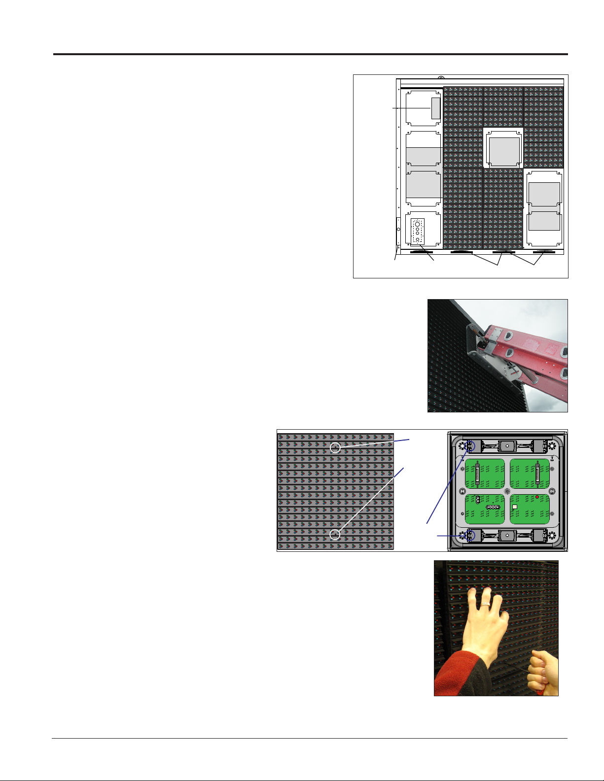
Daktronics Galaxy® AF-35XX series displays are front accessible,
meaning that access to the internal components is gained by
removing the front modules of the display. Figure 10 shows the
approximate location of internal components.
6.1 Proper Ladder Use
A ladder can be used to access displays, although it is
not preferable. If a ladder must be used, do not place the
ladder directly against the display face. The pressure from
the two ladder ends, even when covered with pads, is too
concentrated and can damage the LEDs and louvers.
Instead, use a padded or carpeted board across the top of the ladder to
distribute the weight of the ladder evenly when placed against the display
face, as shown in Figure 11. The padded board should be wide enough to
spread the weight of the ladder across a minimum of two modules.
6.2 Internal Display Access
Thermostat
Power
Supply
Controller
Light Sensor
Figure 10: Interior Component Locations
Quick Connect
Input Board
Filters
Fans
Power
Term.
Panel
Access the display interior to perform maintenance or troubleshooting by
removing the front modules.
1. Disconnect power to the display.
2. Locate the latch access fasteners
on the module as shown in
Figure 12. One is centered near
the top and one is centered near
the bottom.
3. With a 1/8” hex wrench, turn the
Module Latch
latch access fasteners a quarter
turn counter-clockwise, as shown
Figure 12: Module Latch Locations (20 mm)
in Figure 13. Gently pull the
module far enough forward to reach behind it and disconnect the
power and ribbon cables.
4. Disconnect the two ribbon cables from the module by spreading the
tabs on the sides and then lifting the cable head from the jack. Note
the cable connections so they can be reconnected correctly.
5. Unplug the power cables by squeezing the tabs on the sides of the
plug head and pulling out.
Figure 11: Example Ladder Board
1/8 hex
wrench for
access
fasteners
Assembly
6. When ready to reinstall the module, reconnect the cables, making
Figure 13: Removing a Module
sure that the tabs are tightly pushed against the cable head. Carefully
Maintenance 17
Page 22
push the ribbon wires back into the cabinet so they are clear of the module edges.
DAKTRONICS
Galaxy
7. Place the module into its proper location, checking that the weather stripping is in place. Latch the
module at both the top and bottom locations by turning the hex wrench clockwise a quarter turn.
Notes:
• Weather stripping on the back edge of the module must be intact and in good condition to prevent
water from entering the display.
• Module latches must be fully engaged to create a watertight seal around the edge of the module. The
module seats firmly against the display when the latches are fully engaged.
6.3 Ventilation System/Fans
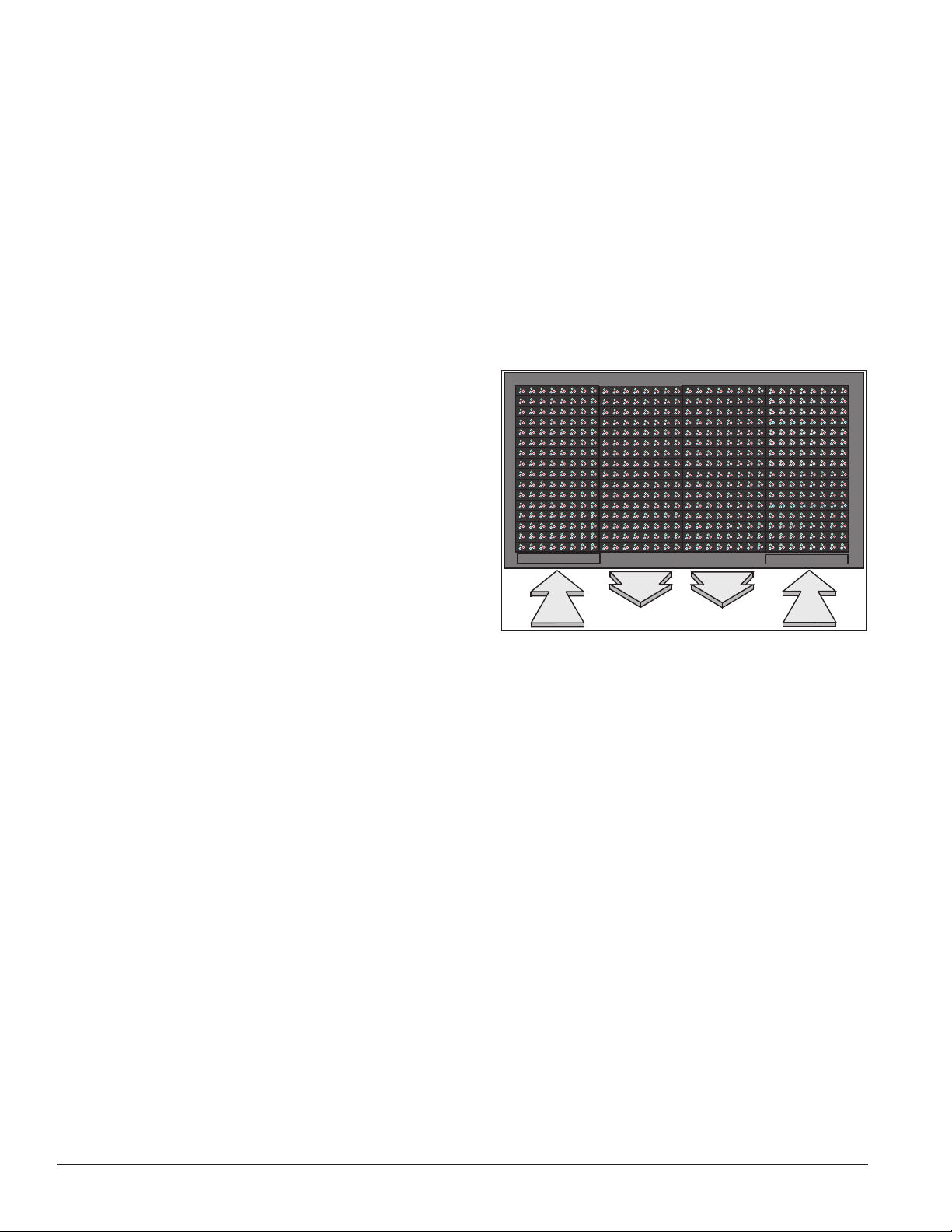
AF-35XX series displays are equipped with ventilation
systems that help keep internal electrical components
at operable temperatures. Intake fans bring air into the
display through vents on the bottom front. Exhaust
leaves the display through adjacent vents along the
bottom front. Figure 14 shows an example of the
display’s airflow.
Note: Air vents are located behind a false face and
cannot be readily seen.
A smaller fan is also located on the display controller
enclosure cover which should always be running.
Frequency of Inspection
Check fans every time the display is opened or at a minimum of once every three months. Check more often
if the display is located in a dusty or harsh environment, such as along a gravel road.
Inspection frequency varies greatly from display to display as no two display installations are exactly the
same. Daktronics advises users and service technicians use their discretion when establishing an inspection
schedule.
Figure 14: Ventilation Airow
Fan Blades
Check the fan blades for dirt and debris. Clean them and the inside of the display if necessary to maintain fan
efficiency and to ensure proper cooling. Spin the fan blades with a pen or pencil to ensure that the bearings
are free and that the fan is in balance.
Filters
Below each intake fan is a filter tray. Each time the fans are inspected, the filters must also be inspected; clean
or replace them when necessary.
To access the filter(s), press upward firmly on the tab located on the bottom front of the tray and pull
outward.
Clean filters with water or compressed air (no greater than 60psi and at least 6" away) blown through the
filter in the opposite direction from which air normally flows. Allow filters to dry before returning them to
their trays. Again, Daktronics encourages users and service technicians to use their own discretion when
deciding whether to clean or replace the filters.
18 Maintenance
Page 23
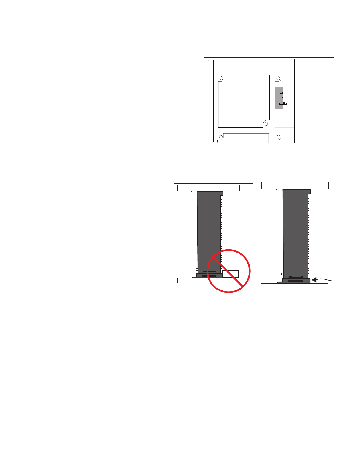
Note: Air is drawn upward through the filter. Be sure to check the bottom of the filter as this will be the side
Thermostat
Bypass
Switch
that requires cleaning.
Fan Test
Once the display’s internal components reach a certain
temperature, the fans are activated. If the fans are
not operating, they may be checked by bypassing the
temperature controls. To check the operation of the
fans, open the display to expose the thermostat in the
upper left-hand corner. Press the test button, shown in
Figure 15, to test fan operation. Some thermostats may
have the button on the bottom. If a fan does not rotate or
does not operate smoothly, replace it.
Make sure that the intake vents and exhaust vents on the
bottom front of the display are not blocked and are free of
dust or other debris. Hold a piece of lightweight paper in
front of the bottom edge (under the filter trays) of the
display to detect air movement through the vents.
Note: When mounting the display, the entire front must be exposed to allow for proper ventilation. Aesthetic
shrouding (common in monument
installations) is not advised. See Figure 16 and
Figure 17 for examples.
Figure 15: Fan Test Button
6.4 Display Face Cleaning
Wet Cleaning Process
1. Turn off power to the display.
2. Mix a mild, non-abrasive, non-petroleum-
based detergent and cold water, one
ounce of detergent to one gallon of cold
water.
3. Saturate a light/medium duty cleaning
brush with the soapy water.
4. Use horizontal brush strokes to loosen and remove dirt and grime, washing the display from top to
bottom. Use light pressure so as not to damage the LEDs. Clean only an area that is safely within reach
from a lift or stage, and then move on to the next section of modules.
5. Rinse the display face with generous amounts of cold water under low pressure.
A spot-free rinse agent can be used to reduce water spots.
6. Use soft, dry terrycloth to dry and remove any excess water. Take care not to damage LEDs by catching
the cloth on them.
BACK
Figure 16: Restricted Airow
FRONT
BACK
Figure 17: Unrestricted Airow
FRONT
7. Allow the display to completely air-dry for 12 hours before applying power to the display.
Maintenance 19
Page 24

Dry Cleaning Process
1. Turn off power to the display.
2. Rub a dry, soft terrycloth towel horizontally across each row of LEDs. Make several passes per row of
LEDs before moving to the next row of LEDs. Work from top to bottom safely within reach from a lift or a
stage. Take care not to damage LEDs or the plastic louvers by catching the cloth on them.
6.5 Annual Inspection
Complete a yearly display inspection to maintain safe and dependable operation. Open the display to visually
inspect the cabinet interior and the components. Refer to Section 6.2 for directions to access the interior.
• Tighten and replace any loose fasteners.
• Vacuum or carefully wipe away dust and debris around the fans and inside the cabinet.
• Check for water intrusion or stains and replace weather stripping, tighten module latches, place
silicone sealant around areas where water might enter, and replace damaged electronic components
as necessary.
• Also, check the paint for cracking and peeling and touch up with rust-resistant enamel as necessary.
• Inspect the footings, tie points, and ground rods for corrosion and make sure the structural integrity
and grounding connections are intact.
A log is provided in Appendix D to track maintenance and help determine a maintenance schedule specific
to the individual display.
20 Maintenance
Page 25
Section 7: Diagnostics and Troubleshooting
DS4 Run
DS2 Receive
DS3
Transmit
Important Notes: Disconnect power when servicing the display. Only qualified service personnel should service
internal electronic components.
7.1 Controller Diagnostics
The controller is the “brains” of the display, receiving
communication from the computer and then sending
information to the modules. The controller is located in
the lower-left area of displays as shown in Figure 10.
LEDs on the controller show whether power and
communication signals are working properly.
Mirror displays do not contain a controller. Instead,
they have an MLC or repeater card which helps relay
information from the primary controller.
To access the interior of the display, refer to Section
6.2 for instructions and illustrations. Remember to
disconnect power to the display before accessing the
interior. However, once the modules are removed and
wires are found to be safe, power can be turned back on
to view the diagnostic LEDs.
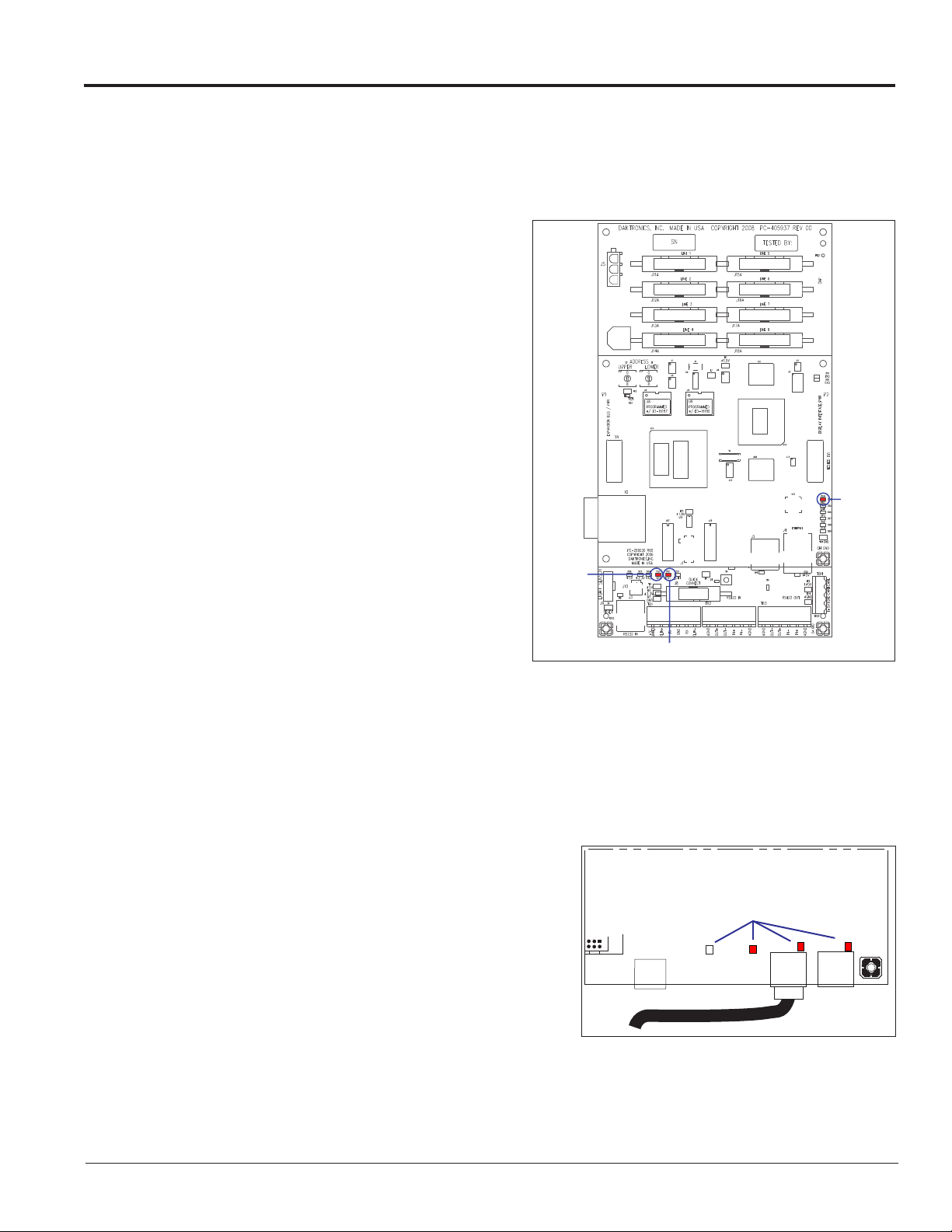
A Galaxy controller is illustrated in Figure 18 with
essential diagnostic LEDs labeled:
• The DS4 LED signifies the controller’s
operational status. This LED flashes about
once per second to indicate the controller is
functioning properly.
• The DS3 LED signals the controller’s transmission status. This LED flashes only when transmitting
information to the modules.
• The DS2 LED displays the controller’s receiving status. This LED flashes only when receiving
information from the control computer.
7.2 MLC Diagnostics
The Multi-Line Controller (MLC) unit contains four red
diagnostic LEDs. When properly connected to the primary
display, the LED labeled DS25 is off and the other LEDs are on,
as shown in Figure 19.
Figure 18: Controller Diagnostics
Diagnostic LEDs
▼
DS23
J25 J21
MLC
▼
DS24 DS25
REPEAT IN
J22
▼
DS27
REPEAT OUT
▼
Figure 19: MLC Diagnostic LEDs
Diagnostics and Troubleshooting 21
Page 26
7.3 Troubleshooting Display Problems
This section contains some symptoms that may be encountered with displays. This list does not include every
symptom or solution but does represent common situations and simple steps to resolve them.
Troubleshooting may require removal and replacement of modules. Refer to Section 6.2 for more
information. When replacing modules, make sure power and signal cables are reconnected correctly and the
latches are tightly closed.
Common Misconceptions
Blank display seen after boot-up
A blank display is normal after the boot-up procedure. When finished, the display is blank except for a
flashing pixel in the lower-right corner. The display is waiting for a message to be sent.
Module and LED Problems
One or more LEDs are not lighting
daktronics Galaxy
• Check/replace the ribbon cables on the
module.
• If that does not help, the module may
need to be replaced.
One or more LEDs on a single module will not
turn off
• Check/replace the ribbon cables on the
module.
• If that does not help, the module may need to be replaced.
A section of the display is not working
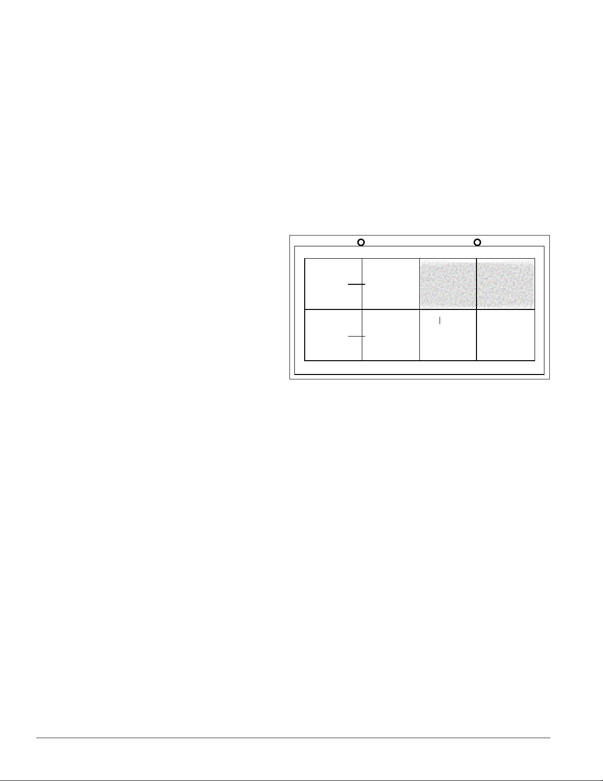
• Check/replace ribbon cables from the last working module in the row to the first non-working
module next to it. Refer to Figure 20.
• Check the back of the modules to see that the power LEDs are on.
• Make sure the power cable to the module is connected.
Signal
Flow
Signal
Flow
Figure 20: Modules Not Working
Last
►
working
module
►
►
First Non-working
Module
• Move or replace the first non-working module with the one on the left of the non-working section.
• Move or replace the first module to the left of the non-working modules.
One row of modules is not working or shows a distorted message
• Check/replace the ribbon cables to and from the first non-working module.
• Check for bent pins on the jack going to a non-working module.
• Move or replace the modules that show distorted text.
• Move or replace the first module to the left of the non-working module.
22 Diagnostics and Troubleshooting
Page 27

A column of the display does not work
• Check that the power cable is plugged into the module in the column.
• While power is on, look at the back of the malfunctioning module(s) to see if the diagnostic LED is
off, implying a power supply problem.
• Verify power to the power supply.
Entire display fails to work
• Check the breakers in the building connected to main power source.
• Check the breakers in the power termination panel.
• Check the diagnostic LEDs on the controller for Power and Run. Refer to Section 7.1 for more
information.
• Check/replace the ribbon cable from the controller to the modules.
• Verify proper use of the software by checking the software manual.
Brightness Problems
Display is stuck on bright or dim
• Check Manual/Auto dimming in Venus 1500 software. Brightness is typically set to Automatic. If
not, refer to the Venus 1500 software manual (DD1370296) for more information.
• Check the light sensor cable and wiring for secure connections.
• Check the light sensor lens for obstructions (lower-left edge, front of primary cabinet).
• Replace the light sensor assembly.
Message Problems
Message only shows up on one side of the display
Determine if the displays are set up as two primary displays or one primary and one mirror display. To do
this, turn off the power, then turn it back on and observe the two display faces. If the setup involves two
primary displays, one should show “HW1” and the other “HW2”.
• Verify that two different addresses are setup for these two primary displays. Refer to the Venus 1500
software manual for more information.
• Verify that two different addresses are set on the controller(s).
• Send a different message to each display separately by clicking on that display name in the list.
Note: With two controllers, messages may not always run simultaneously.
• If the setup consists of a primary/mirror display, check the cable between them.
• Check that the cable and plugs are in good condition.
• Check that the MLC in the mirror display has power.
Diagnostics and Troubleshooting 23
Page 28

• Check the dip switches on the MLC. They should be in the down position.
Temperature Problems
(For displays with a temperature sensor installed)
No temperature showing on the display
• Refer to the Venus® 1500 software manual (DD1370296) for more information.
Note: The temperature sensor must be correctly installed before a current temperature can be shown.
Temperature always reads –196F/-127C degrees
• Check the temperature sensor cable connections.
• Look for bent pins on connectors.
• Check that the temperature sensor is set to address 1.
• Make sure the sensor has power by checking that the diagnostic LED is blinking.
Temperature Problems
No temperature showing on the display
• Refer to the Venus® 1500 software manual (DD1370296) for more information.
Note: The temperature sensor must be correctly installed before a current temperature can be shown.
Testing Displays
Start and stop the test pattern
• Refer to the Venus® 1500 software manual (DD1370296) for more information.
Note: This procedure must be done for each primary display being tested.
Before Calling For Help
Steps to take before calling Daktronics Customer Service
1. Turn off the power breaker switch. Wait a few minutes and turn it back on. Watch the display(s) to
make sure that the initialization sequence runs.
2. Once the sequence is complete, try to communicate with the display.
3. Check the Communication and Troubleshooting sections of this manual.
4. Call the service technician or Daktronics Customer Service at 866-343-3122.
Note: Sitting at the control computer while talking with the service technician allows more efficient
service.
24 Diagnostics and Troubleshooting
Page 29
Section 8: Parts Replacement
Important Notes: Disconnect power when servicing the display. Only qualified
service personnel should service internal electronic components.
0P-1127-0024
8.1 About Replacement Parts
The following table contains some of the items that may need to be replaced
in a display over a period of time. These components are generally located
as shown in Figure 10. If a component is not listed in the replacement parts
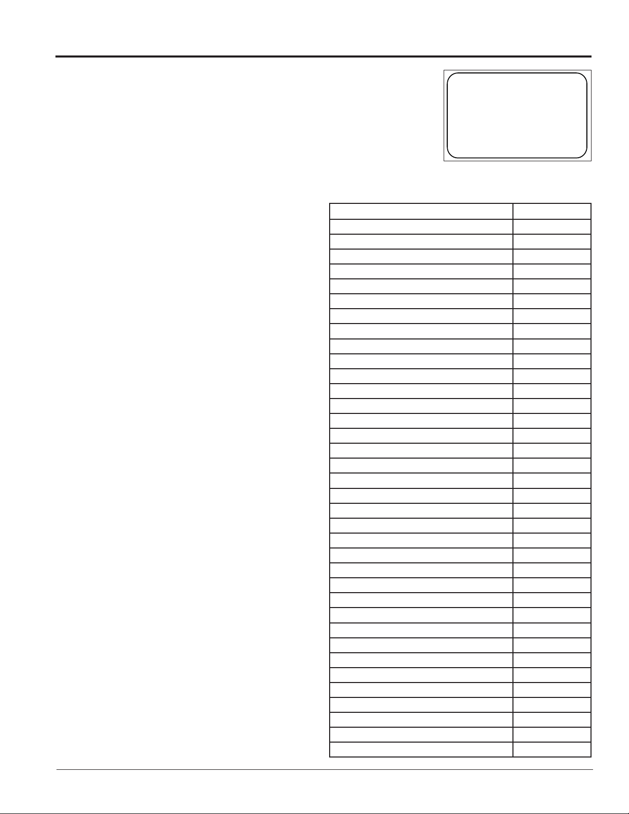
list, use the label to order a replacement. Most components within this display carry a label that lists the part
number of the unit. A typical label is shown in
Figure 21 with the part number in bold.
8.2 Instructions for Replacing Parts
Module Replacement
Tool Required: 1/8” Hex Wrench
If LEDs have failed, do not attempt to replace
individual LEDs. Return a failed module to
Daktronics for replacement and/or repair.
Each module can be removed separately without
moving other components of the display.
1. Turn off power to the display.
2. Follow the instructions in Section 6.2
to release the module from the display
cabinet.
3. Disconnect the two ribbon cables from the
module, noting how they are connected
to the back. Release ribbon cables by
spreading the tabs on the sides and then
lifting the cable head from the jack.
4. Unplug the power cables by squeezing
the tabs on the sides of the plug head and
pulling out.
5. Connect all three cables to the new
module, making sure that the ribbon cable
tabs are tightly pushed against the cable
head. Carefully push the ribbon wires
back into the cabinet so they are clear of
the module edges.
6. Place the module into its proper location,
checking that the weather stripping is in
place. Latch the module tightly at both top
and bottom by turning the hex wrench a
quarter turn clockwise.
SN: 2465
02/19/12 Rev. 1
Figure 21: Typical Parts Label
Part Description Part Number
Module; AF-3500 34 mm Amber 0A-1208-5009
Module; AF-3500 34 mm Red 0A-1208-5005
Module; AF-3550 34 mm RGB 0A-1208-5650
Module; AF-3500 20 mm Amber 0A-1266-5017
Module; AF-3500 20 mm Red 0A-1266-5005
Module; AF-3550 20 mm RGB 0A-1266-5650
Module; AF-3550 16 mm RGB 0A-1569-5551
M3 Controller III 0A-1382-0016
MLC 0P-1273-0067
Power Supply, 3-6.5V A-2307
Transformer T-1119
Transformer, International T-1121
RFI Filter Z-1007
Relay K-1040
Temperature Sensor 0A-1151-0011
Thermostat 0A-1327-3103
Light Level Detector 0P-1151-0002
Light Sensor Assembly 0A-1327-3000
Fan, Ventilation B-1053
Filter, Air EN-2310
Primary signal input, Serial 0P-1415-2000
Primary signal input, RJ45 J-1474
Primary signal output / Mirror signal input J-1470
Cable; RJ45, CAT5E, Shielded, 2’ W-1537
Cable; RJ45, CAT5E, Shielded, 20’ W-1547
Cable; 22 Awg 2-Pair, Dual Foiled, Single W-1234
Cable Assy; 20 pos Ribbon, 18”, Dual Row W-1387
Ribbon Assy; 10 Pos. @ 24” 0A-1000-0074
Ribbon Assy; 20 Pos, 24” 0A-1000-0016
Ribbon Assy; 20 Pos, 30” 0A-1000-0017
Ribbon Assy; 20 Pos, 42” 0A-1000-0019
Ribbon Assy; 20 Pos, 60” 0A-1000-0021
Ribbon Assy; 20 Pos, 72” 0A-1000-0022
Ribbon Assy; 20 Pos, 84” 0A-1000-0023
Interconnect Cable; RJ45 W-1921
Electrical Contact Cleaner/Lubricant CH-1020
Parts Replacement 25
Page 30
Notes:
• Weather stripping on the back edge of the module must be in good condition and returned to its
proper position to prevent water from entering the display.
• Module latches must be fully engaged to create a watertight seal around the edge of the module. The
module seats firmly against the display when the latches are fully engaged.
Controller Replacement
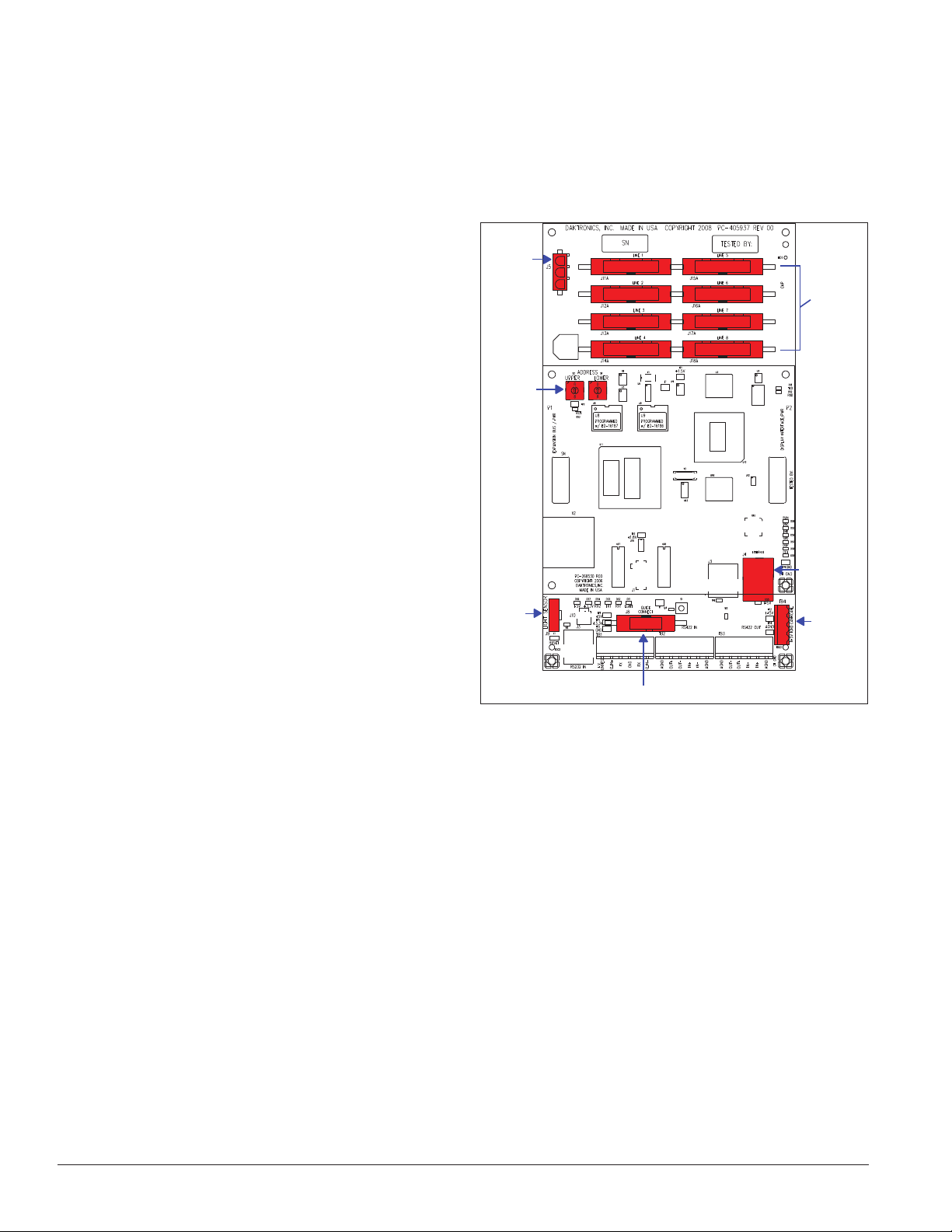
Tools required: 1/8" hex wrench, 5/16" nut driver, and
flathead screwdriver
Complete the following steps to replace a controller
in the display:
1. Turn off power to the display.
2. Remove the module directly in front of
the controller in the lower left area of the
display. Refer to Figure 10 for the location.
3. Loosen screws and remove the cover in
front of the controller.
Power
Input
Address
Switches
Module
Outputs
4. Disconnect the power input.
5. Remove all power and signal connections
from the board. Label the cables as they are
removed to ensure proper replacement.
6. Remove the six nuts holding the board in
place using a 5/16" nut driver.
7. Take note of the rotary address on the
controller to ensure the address on the
replacement board is the same. See
Light
Sensor
Input
Quick Connect Input
Figure 22: Galaxy Controller
Ethernet
Input
CAN
Input
Figure 22.
8. To install the new controller, replace the six nuts holding it to the display back. Reconnect power and
signal cables. Turn on power, observe the boot-up sequence, and note that the pixel in the lower-right
corner shows power.
26 Parts Replacement
Page 31
Controller Address Setting
Upper Lower
Address 1
0 – 1
Address 2
0 – 2
0
1
2
3
4
5
6
7
8
9
A
B
C
D
E
F
0
1
2
3
4
5
6
7
8
9
A
B
C
D
E
F
0
1
2
3
4
5
6
7
8
9
A
B
C
D
E
F
0
1
2
3
4
5
6
7
8
9
A
B
C
D
E
F
0
1
2
3
4
5
6
7
8
9
A
B
C
D
E
F
0
1
2
3
4
5
6
7
8
9
A
B
C
D
E
F
Address 16
1 – 0
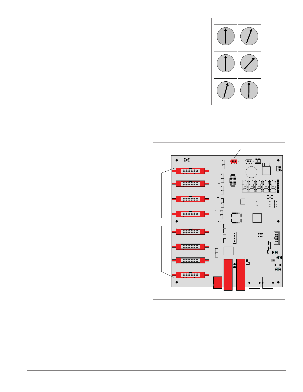
The rotary switches set the hardware address which the software uses
to identify each particular display. Each controller in a network needs a
unique address.
To set the rotary address switches, rotate them until the arrow points to
the desired number, as shown in Figure 23. The display’s power must be
turned off and then turned back on to activate the test mode or to change
an address.
Notes:
• Setting both rotary switches to address 0 will activate Test Mode.
Turn the display’s power off and back on to activate testing.
• After testing, reset the rotary switches to an address other than 0/0
and repower the controller (the software will not recognize an address of 0).
MLC Replacement
Tools required: 1/8" hex wrench, 5/16" nut driver,
and flathead screwdriver
In mirror displays, the Multi-Line Controller
(MLC) receives signal from the primary
controller and distributes it to the modules.
Ribbon cables run from the module connectors
on the MLC to the first modules in each row
via ribbon cables. The power supply nearest the
MLC will provide its power via a transformer in
the enclosure with the MLC.
1. Turn off power to the display.
2. Remove the module directly in front
of the MLC. Refer to Figure 10 for the
approximate location.
3. Disconnect the input cables.
4. Remove all ribbon cables, labeling the
module number as they are removed to
ensure proper replacement.
Module
Connectors
Module 0
Module 1
Module 2
Module 3
Module 4
Module 5
Module 6
Module 7
Figure 23: Rotary Address Switches
Power
7-24 VDC
Program
Parts Replacement 27
5. Remove the six nuts holding the board
Fiber
in place using a 5/16" nut driver.
6. To install the new MLC, move the
Note: Ensure all dip switches on the MLC are in the down position.
unit into place and replace the six nuts
holding it to the display back. Reconnect input and ribbon cables. Turn on power, observing the bootup sequence. Note that the LEDs to the right of the fiber jacks are on; DS23 to the left of the fiber cable
should be off. Refer to Figure 19 and Figure 24 for more information.
Figure 24: Multi-Line Controller
Fan
Control
Fiber
In
Out
Page 32
Power Supply Replacement
Tool required: Phillips screwdriver
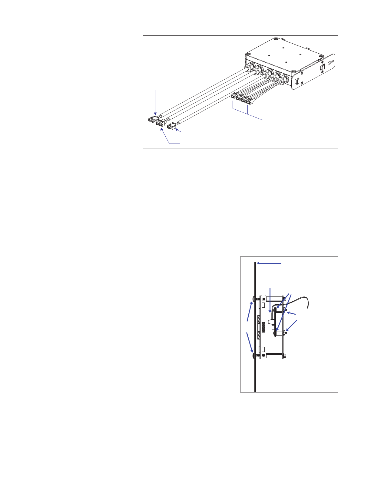
Galaxy displays use 135-watt
power supplies that run up to four
modules (eight modules in 34 mm
monochrome displays).
Each module is connected to a
wire harness on the power supply
by a Mate-n-Lok® cable. Refer to
Figure 25 for an example.
Complete the following steps to
replace a power supply:
AC Input
(From Power
Source)
DC Outputs (To Modules)
V Adjust (To Initial Module)
1. Turn off power to the
display.
Figure 25: Power Supply
AC Output (To Next Power Supply)
2. Remove the module directly in front of the appropriate power supply.
3. Disconnect the Mate-n-Lok® connectors from the power source as well as those going to the modules.
Be sure to label each connector so that it can be properly reconnected.
4. Loosen the screw holding the power supply bracket to the cabinet upright and lift it off the hooks.
5. Carefully pull the power supply out of the cabinet.
6. Move the new power supply into place and tighten the screw on the support bracket.
7. Reconnect all the Mate-n-Lok® plugs so that each module will receive power.
Light Sensor Replacement
Front Panel of Display
Tools required: 3/16" nut driver, Phillips screwdriver
The light sensor assembly is mounted inside the bottom-left edge of the
cabinet. Refer to Figure 10 for location.
4
3
If the light sensor fails, only the circuit board needs to be replaced.
Remove the bottom-left module on the display to access the light sensor.
To replace a light sensor circuit board as shown in Figure 26, follow
these steps:
1
2
1. Remove the screws that hold the light sensor to the cabinet.
2. Remove the #4-40 nuts securing the circuit board to the plate.
3. Remove the standoffs and attachment screws from the board.
4. Disconnect the four electrical wires on the sensor by unscrewing
each screw that holds a wire in place. Note the order the wires
are connected so they can be reconnected in the same locations
Figure 26: Light Sensor Assembly
on the replacement.
5. The light sensor plug on the controller does not need to be detached.
6. Reattach the new circuit board, following these steps in reverse.
28 Parts Replacement
Page 33
Note: Align the new circuit board so that the lens lines up with the 1/2”circular opening in the bottom left
edge of the display when the assembly is in place.
Temperature Sensor Replacement
Tools required: Phillips screwdriver
If the temperature sensor malfunctions,
replace the entire unit.
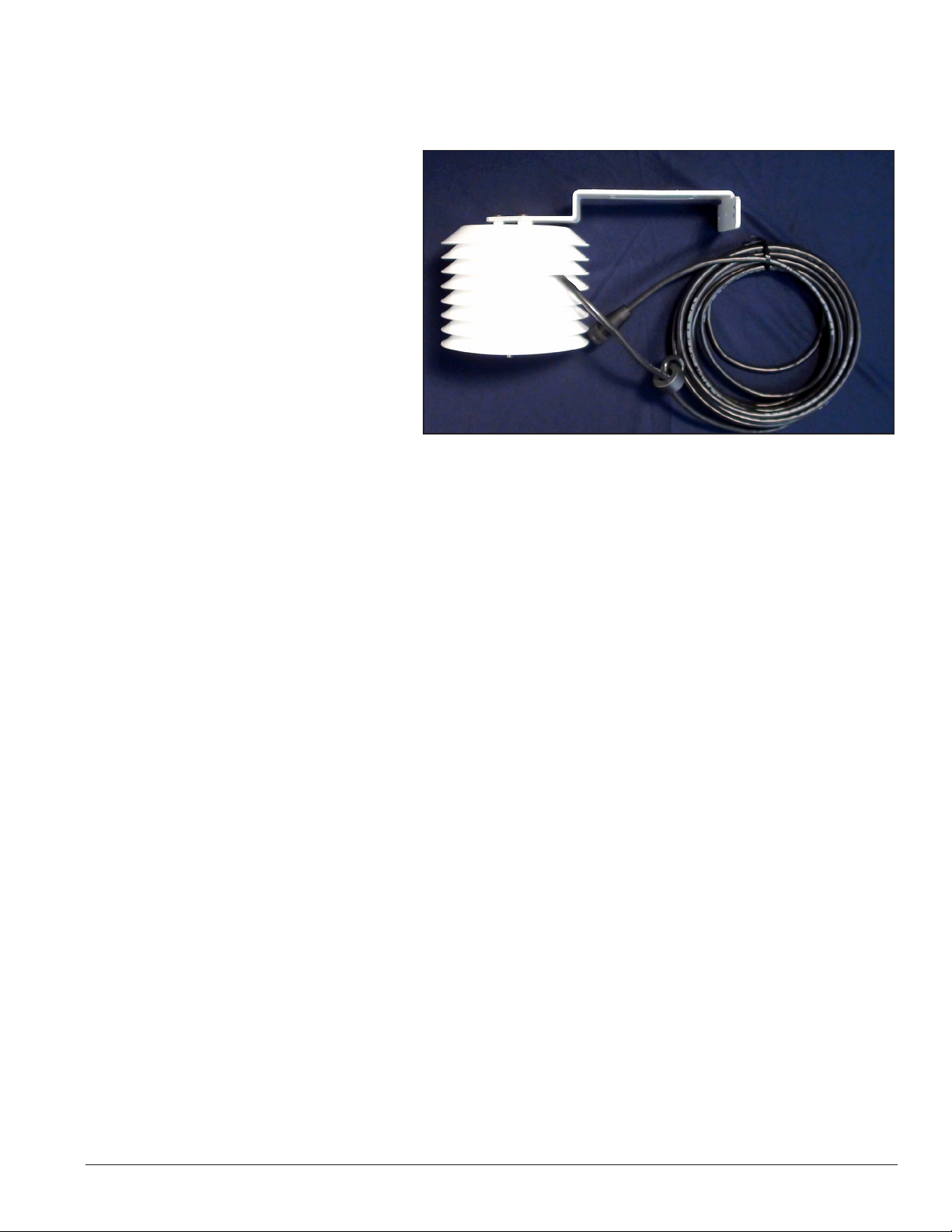
The temperature sensor enclosure,
shown in Figure 27, is composed of
eight plastic disks, a metal mounting
bracket, and a 25-foot weather-resistant
cable.
In most cases, the enclosure is mounted
using four screws. The cable plugs into
quick-connect jack J31 on the back of
the display.
Figure 27: Temperature Sensor and Mounting Bracket
Parts Replacement 29
Page 34

Page 35

Section 9: Daktronics Exchange and
Repair & Return Programs
9.1 Exchange Program
The Daktronics Exchange Program is a quick, economical service for replacing key components in need
of repair. If a component fails, Daktronics sends a replacement part to the customer who, in turn, returns
the failed component to Daktronics. This not only saves money but also decreases equipment downtime.
Customers who follow the program guidelines explained below will receive this service.
Before Contacting Daktronics
Fill in these numbers before calling Customer Service:
Display Model Number: ________________________________________
Date Installed: ________________________________________________
Location of Display: ___________________________________________
Daktronics Customer ID Number: _______________________________
To participate in the Exchange Program, follow these steps:
1. Call Daktronics Customer Service: 866-343-3122.
2. When the new exchange part is received, mail the old part to Daktronics.
If the replacement part fixes the problem, send in the problem part which is being replaced.
a. Package the old part in the same shipping materials in which the replacement part arrived.
b. Fill out and attach the enclosed UPS shipping document.
c. Ship the part to Daktronics.
3. A charge will be made for the replacement part immediately, unless a qualifying service agreement is
in place. In most circumstances, the replacement part will be invoiced at the time it is shipped.
If the failed part or replacement part is not returned to Daktronics within 3 weeks of the ship date, Daktronics
will assume that the customer is purchasing the replacement part and will send an invoice for the value of
the new sale part. If the part or parts are returned within 2 weeks of the second invoice date, Daktronics will
credit the customer for the second invoice.
If after 2 weeks Daktronics has still not received the parts back, the customer must pay the second invoice
and will not be credited for the return of the failed part. Daktronics reserves the right to refuse parts that have
been damaged due to acts of nature or causes other than normal wear and tear.
Daktronics Exchange and Repair & Return Programs 31
Page 36

9.2 Repair & Return Program
For items not subject to exchange, Daktronics offers a Repair & Return Program. To send a part for repair,
follow these steps:
1. Call or fax Daktronics Customer Service:
Phone: 866-343-3122 Fax: 605-697-4444
2. Receive a Return Materials Authorization (RMA) number before shipping.
This expedites repair of the part.
3. Package and pad the item carefully to prevent damage during shipment.
Electronic components, such as printed circuit boards, should be placed in an antistatic bag before
boxing.
4. Enclose:
• Your name
• Address
• Phone number
• The RMA number
• A clear description of symptoms
Shipping Address
Daktronics Customer Service
PO Box 5128
201 Daktronics Dr.
Brookings SD 57006
9.3 Daktronics Warranty and Limitation of Liability
The Daktronics Warranty and Limitation of Liability is located in Appendix E:. The Warranty is independent
of Extended Service agreements and is the authority in matters of service, repair, and display operation.
32 Daktronics Exchange and Repair & Return Programs
Page 37

Glossary
Cabinet: The metal frame of the display (back, sides, top, and bottom).
Column: A vertical line of pixels.
Controller: The “brains” of the display. The controller receives signal communication from the computer and sends
the information to the modules. Messages and schedules may also be stored on the controller for use when desired.
Display Address: An identification number assigned to each display of a network. The control software uses the
address to locate and communicate with each display. Displays that are on the same network must have different
addresses.
Galaxy®: One of Daktronics’ trademarked names for commercial LED matrix displays.
Light Emitting Diode (LED): A low energy, high intensity lighting element. When grouped together, LEDs produce
the messages that appear on the display.
Louver: Black plastic ledge positioned horizontally above each pixel row. Louvers block sunlight to increase the level
of contrast on the display face.
Mirror: The second display in a two-sided (2V) configuration. The mirror display does not have a controller, but
rather an MLC. It displays an exact copy of the information on the primary display. All signal information to the
mirror is received through an inter-connect cable from the primary display.
Multi-LineController(MLC): Used in mirror displays to repeat data from the primary display and to control the
mirror display’s ventilation fans.
Module: Modules are the “building blocks” of the display. Individual module sizes vary depending on the pixel pitch
of the display. Each module is individually removable from the front of the display.
Network: Consists of multiple displays connected to each other. As many as 240 primary displays can exist on one
network.
Picture Element (Pixel): A single LED or cluster of LEDs. The number and color of the LEDs depends on display
application.
Pixel Pitch: The amount of space between the center of two pixels. The pixel pitch is equidistant both vertically and
horizontally.
Primary: The first display in a two-sided (2V) configuration. The communication signal, light sensor, and temperature
sensor are connected to this display. Information is relayed from the primary through an inter-connect cable to the
MLC in the mirror so it shows exactly the same information.
Venus 1500 Software: The software on the control computer used to create messages and send them to displays. The
Venus 1500 software manual is included on the software’s installation disk.
Glossary 33
Page 38

Page 39

Appendix A: Reference Drawings
Shop drawings show display dimensions, signal and power connection locations, as well as information on service
access and power requirements. To obtain copies of shop drawings or other reference drawings specific to your
display, use the links listed below or contact Daktronics Customer Service:
Phone: 866-343-3122 Fax: 605-697-4444
Click here for AF-3500 shop drawings.
Click here for AF-3550 shop drawings.
Click here for layout drawings.
Appendix A: Reference Drawings 35
Page 40

Page 41

Appendix B: Temperature Sensor Installation (DD2638167)
Click here to open the temperature sensor installation quick guide.
Appendix B: Temperature Sensor Installation (DD2638167) 37
Page 42

Page 43
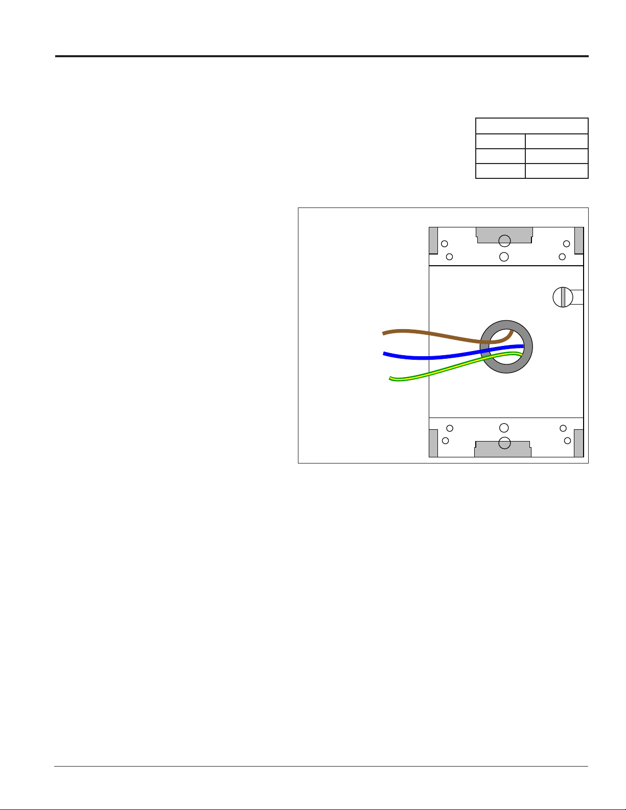
Appendix C: International Installation
The biggest difference between domestic and international applications is the power sources. International displays
run on 240 VAC.
Terminating hot, neutral, and ground wires at the J-box
1. Route the power cable through conduit to the rear of the display and into the
power termination J-box.
2. The power termination enclosure contains two wires plus a ground coming
from the interior of the display. These wires are pre-terminated to the power
termination panel inside the display.
240 VAC Termination
3. Inside the display’s external power
termination J-box, connect the power
wires to the wires coming from the
display interior using wire nuts. Refer
to Figure 28.
Note: The following colors are used for
the pre-terminated wires:
Terminating single-phase power
to the internal power termination
panel
Daktronics’ displays used for international
applications are equipped with different
power termination panels than domestic
displays. However, the termination method
is similar to the domestic termination
discussed in Section 3.6.
Line 1 – Brown
Neutral – Blue
Ground –Green/Yellow
(Box with Cover Removed)
Wiring from power termination
panel inside display
240 VAC
Line 1 Brown
Neutral Blue
Ground Green/Yellow
1. Open the display as explained in
Section 6.2 and locate the power
termination panel.
2. Route the cable through conduit to the back of the display. Use the 3/4” knockout for access, being careful
not to damage internal components.
3. Remove the cover of the power termination panel.
4. Connect the neutral wire to the neutral lug and the live wire to the Line 1 lug.
5. The ground wire connects to the grounding bus bar.
Figure 28: 240 V Power Termination
Appendix C: International Installation 39
Page 44

Page 45
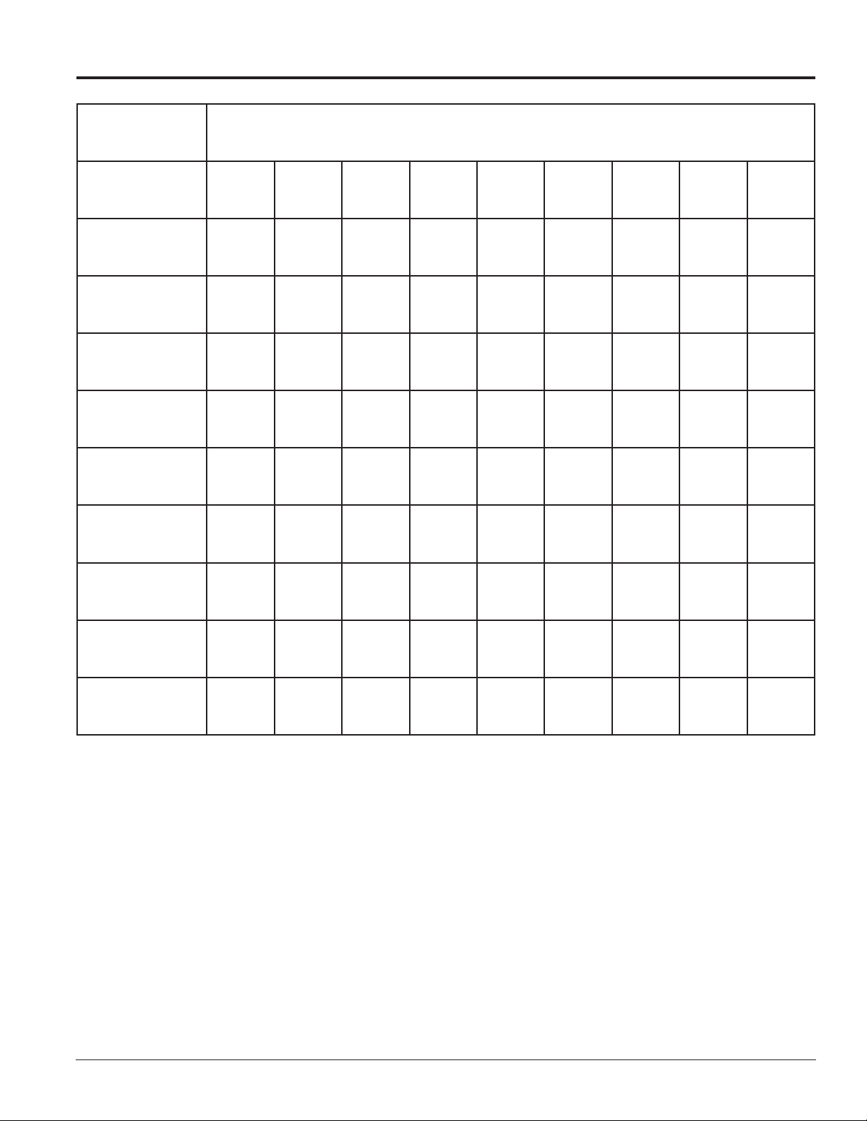
Appendix D: Maintenance Log
Inspection Item: Date performed:
General: Exterior
Visual Inspection
General: Interior
Visual Inspection
Modules: Weather
Stripping
Modules: Electrical
Connections
Modules: Latch
Operation
Ventilation System:
Fans
Ventilation System:
Filters
Hardware/Fasteners:
Loose bolts, nuts,
screws, rivets, etc.
Cabinet (Int. & Ext.):
Paint cracking and
peeling
Cabinet (Int. & Ext.):
Metal Corrosion
Appendix D: Maintenance Log 41
Page 46

Page 47

Appendix E: Daktronics Warranty and
Limitation of Liability (SL-02374)
Click here to view Warranty and Limitation of Liability information.
Appendix E: Daktronics Warranty and Limitation of Liability (SL-2374) 43
 Loading...