

Page 1

201 Daktronics Drive PO Box 5128 Brookings, SD 57006-5128
Tel: 1-800-DAKTRONICS (1-800-325-8766) Fax: 605-697-4700
Web: www.daktronics.com Email: helpdesk@daktronics.com
CR-2004 Multi-Section
Cricket Scoreboard
Display Manual
ED-16242 Rev 1 – 4 March 2011
Page 2

Page 3

ED-16242
Please fill in the information below to use for reference when calling Daktronics for assistance.
Display Serial No. _______________________________________________________
Display Model No. _______________________________________________________
Date Installed ___________________________________________________________
Product 1344
Rev 1 – 4 March 2011
DAKTRONICS, INC.
Copyright 2003-2011
All rights reserved. While every precaution has been taken in the preparation of this manual, the publisher
assumes no responsibility for errors or omissions. No part of this book covered by the copyrights hereon may be
reproduced or copied in any form or by any means – graphic, electronic, or mechanical, including photocopying,
taping, or information storage and retrieval systems – without written permission of the publisher.
All Sport® and PanaView® are trademarks of Daktronics, Inc. Other trademarks used in this manual are the property of their
respective owners.
Page 4

Page 5

Table of Contents
Section 1: Introduction ............................................................................................................................ 1
1.1 Resources .................................................................................................................................. 1
1.2 Daktronics Nomenclature ...................................................................................................... 2
1.3 Model Number ........................................................................................................................ 3
1.4 Scoreboard Controllers ........................................................................................................... 3
1.5 Product Safety Approval........................................................................................................ 3
Section 2: Specifications .......................................................................................................................... 5
Section 3: Mechanical Installation ........................................................................................................ 7
3.1 Footings & Beams .................................................................................................................... 7
3.2 Lifting the Scoreboard ............................................................................................................ 7
3.3 Scoreboard Mounting ............................................................................................................. 8
Clamping to Verticals ...................................................................................................... 9
Welding to Horizontals ................................................................................................. 10
3.4 Ad Panel Mounting............................................................................................................... 11
3.5 Scoreboard Protective Devices ............................................................................................ 12
Section 4: Electrical Installation .......................................................................................................... 13
4.1 Installation Overview ........................................................................................................... 13
All Sport Backup ............................................................................................................ 14
4.2 Power ...................................................................................................................................... 15
Grounding ....................................................................................................................... 15
Connection ...................................................................................................................... 16
4.3 Power-On Self-Test (POST) ................................................................................................. 17
Radio Settings ................................................................................................................. 18
4.4 Signal Connection ................................................................................................................. 18
Fiber Optic ...................................................................................................................... 19
4.5 Power/Signal Connections Between Sections ................................................................... 19
4.6 Lightning Protection ............................................................................................................. 19
Section 5: Scoreboard Troubleshooting ............................................................................................. 21
5.1 Troubleshooting Table .......................................................................................................... 21
5.2 Component Access ................................................................................................................ 23
5.3 Component Locations ........................................................................................................... 24
5.4 Replacing Digits & Indicators .............................................................................................. 24
5.5 LED Drivers ........................................................................................................................... 25
Replacing a Driver ......................................................................................................... 26
Setting the Driver Address ........................................................................................... 27
5.6 Radio Connections ................................................................................................................ 27
Radio Interference .......................................................................................................... 28
5.7 Segmentation and Digit Designation .................................................................................. 29
5.8 Schematics .............................................................................................................................. 29
5.9 Replacement Parts ................................................................................................................. 29
5.10 Daktronics Exchange and Repair & Return Programs ..................................................... 30
Exchange Program ......................................................................................................... 30
Repair & Return Program ............................................................................................. 31
Daktronics Warranty and Limitation of Liability ...................................................... 31
Table of Contents i
Page 6

Section 6: TNMC Troubleshooting & Maintenance ........................................................................ 33
6.1 Team Name Message Center System Overview ............................................................... 33
6.2 Initialization Information at Startup ................................................................................... 33
6.3 Display Troubleshooting Table ........................................................................................... 34
6.4 Power & Signal Summary .................................................................................................... 35
6.5 Component Locations & Access .......................................................................................... 36
For Displays Built Before September 2009 .................................................................. 36
Front Access .................................................................................................................... 37
Rear Access ..................................................................................................................... 37
6.6 Display Drivers ...................................................................................................................... 37
Diagnostic LEDs ............................................................................................................. 39
Replacing a Driver ......................................................................................................... 39
6.7 Modules .................................................................................................................................. 39
Replacing Modules ........................................................................................................ 40
Weather-stripping .......................................................................................................... 41
6.8 Power Supplies ...................................................................................................................... 41
Replacing a Power Supply ............................................................................................ 41
6.9 Display Maintenance ............................................................................................................ 41
6.10 Replacement Parts List ......................................................................................................... 42
For Displays Built Before September 2009 .................................................................. 42
Section 7: Additional Scoreboard Options ........................................................................................ 43
7.1 Radio Control ......................................................................................................................... 43
Appendix A: Reference Drawings ............................................................................................................ 45
Appendix B: Supplemental Manuals ....................................................................................................... 47
Appendix C: Daktronics Warranty and Limitation of Liability .......................................................... 49
ii Table of Contents
Page 7
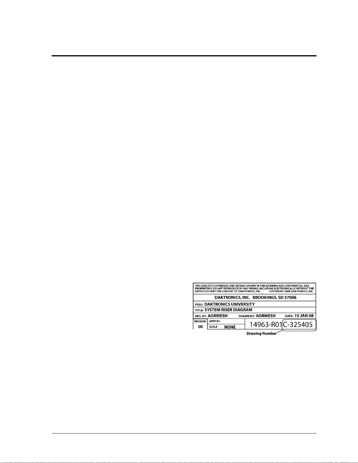
Figure 1: Daktronics Drawing Label
Section 1: Introduction
This manual explains the installation of Daktronics multi-section cricket scoreboard model CR-2004
and provides details for maintenance and troubleshooting. For additional information regarding the
safety, installation, operation, or service of this system, refer to the telephone numbers listed in
Section 5.10. This manual is not specific to a particular installation.
Important Safeguards:
Please read and understand all instructions before beginning the installation process.
Do not drop control equipment or allow it to get wet.
Do not disassemble control equipment or electronic controls of the display; failure to
follow this safeguard will make the warranty null and void.
Disconnect display power when not in use or when servicing.
Disconnect display power before servicing power supplies to avoid electrical shock.
Power supplies run on high voltage and may cause physical injury if touched while
powered.
Do not modify the scoreboard structure or attach any panels or coverings to the
scoreboard without the express written consent of Daktronics, Inc.
Project-specific information takes precedence over any other general information found in
this manual.
1.1 Resources
Figure 1 illustrates a Daktronics drawing
label. The drawing number is located in the
lower-right corner of a drawing. This
manual refers to drawings by listing the last
set of digits and the letter preceding them.
In the example, the drawing would be
referred to as Drawing C-325405.
Reference Drawing:
System Riser Diagram ........................................................................... Drawing C-325405
Daktronics identifies manuals by the DD or ED number located on the cover page of each
manual. For example, this manual would be referred to as ED-16242.
Introduction 1
Page 8
Main Component Labels
Part Type
Part Number
Individual circuit board
0P-XXXX-XXXX
Assembly; a collection of circuit boards
0A-XXXX-XXXX
Wire or cable
W-XXXX
Fuse
F-XXXX
Transformer
T-XXXX
Metal part
M-XXX
Fabricated metal assembly
0S-XXXXXX
Specially ordered part
PR-XXXXX-X
Accessory Labels
Component
Label
Termination block for power
or signal cable
TBXX
Grounding point
EXX
Power or signal jack
JXX
Power or signal plug for the
opposite jack
PXX
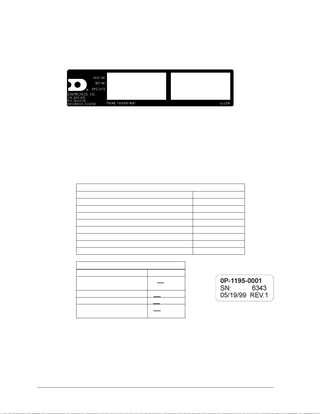
Figure 2: Scoreboard ID Label
Figure 3: Typical Label
1.2 Daktronics Nomenclature
Serial and model numbers can be found on the ID label on the display as shown in Figure 2.
Please list the model number, display serial number, and the date this display became
operational in the blanks provided on the second page of this manual. When calling
Daktronics customer service, please have this information available to ensure the request is
serviced as quickly as possible.
Most components within this display carry a white label that lists the part number of the unit.
If a component is not found in the Replacement Parts List in Section 5.9, use the label to order
a replacement. Figure 3 illustrates a typical label. The part number is in bold.
Following the Replacement Parts List is the Daktronics Exchange Policy and the Repair &
Return Program. Refer to these instructions if replacing or repairing any display component.
2 Introduction
Page 9
CR
Cricket
-11
120 V, with red digits
-21
120 V, with amber digits
-12
240 V, with red digits
-22
240 V, with amber digits
1.3 Model Number
Daktronics scoreboards are differentiated by their model numbers and two-letter prefixes for
each sport. Most Daktronics scoreboards also carry a two-number suffix that refers to the type
of power supply and digit color. Refer to the following tables:
1.4 Scoreboard Controllers
If the CR-2004 is controlled by the Total Cricket Scorer software, refer to the quick guide in
Appendix B.
While the CR-2004 cricket scoreboard is designed for use with third-party computer software,
it is possible to control this scoreboard (with limited functionality) using an All Sport® 5000
series control console. This console uses keyboard overlays (sport inserts) to control
numerous sports and scoreboard models. Refer to the following manual for operating
instructions:
All Sport 5000 Series Control Console Operation Manual (ED-11976)
This control console manual is available online at www.daktronics.com/manuals.
1.5 Product Safety Approval
Daktronics outdoor scoreboards are ETL listed and tested to CSA standard for outdoor use.
Contact Daktronics with any questions regarding testing procedures.
Introduction 3
Page 10

Page 11
Model
Number of
Sections
Dimensions:
Height (H), Width (W), Depth (D)
Weight
Watts
Amps
240 / 120 V AC
Driver #
& Address
CR-2004
4 Total
H 23'-0", W 19'-8", D 8"
(7010 mm, 5994 mm, 203 mm)
1830 lb
(830 kg)
1900 W
7.9 A / 15.8 A
(see below)
Top
(CR-2005)
H 6'-4", W 19'-8", D 8"
(1930 mm, 5994 mm, 203 mm)
500 lb
(227 kg)
A1 15
TNMC 221
2nd from Top
(CR-2006)
H 5'-6", W 19'-8", D 8"
(1676 mm, 5994 mm, 203 mm)
440 lb
(200 kg)
A1 16
A2 17
3rd from Top
(CR-2007)
H 6'-8", W 19'-8", D 8"
(2032 mm, 5994 mm, 203 mm)
530 lb
(240 kg)
A1 18
A2 19
A3 20
TNMC 223
Bottom
(CR-2008)
H 4'-6", W 19'-8", D 8"
(1372 mm, 5994 mm, 203 mm)
360 lb
(163 kg)
A1 21
A2 22
TNMC 222
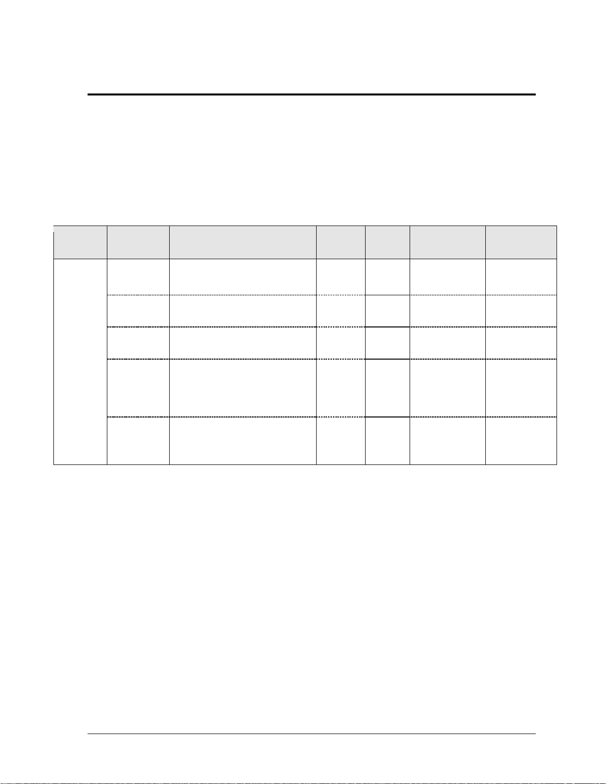
Section 2: Specifications
The chart on the following pages details all of the mechanical specifications, circuit specifications and
power requirements for each display in this manual. Models are listed in alphanumeric order.
Notes:
1) Display requires a 240 V AC, 15 A circuit. Displays with a 120 V A C power requirement
are also available.
2) Signal wire must be minimum of 22 AWG with shield. Daktronics recommends W-1234.
3) Message Center LEDs are the same color as the LED digits on the scoreboard.
Specifications 5
Page 12

Page 13
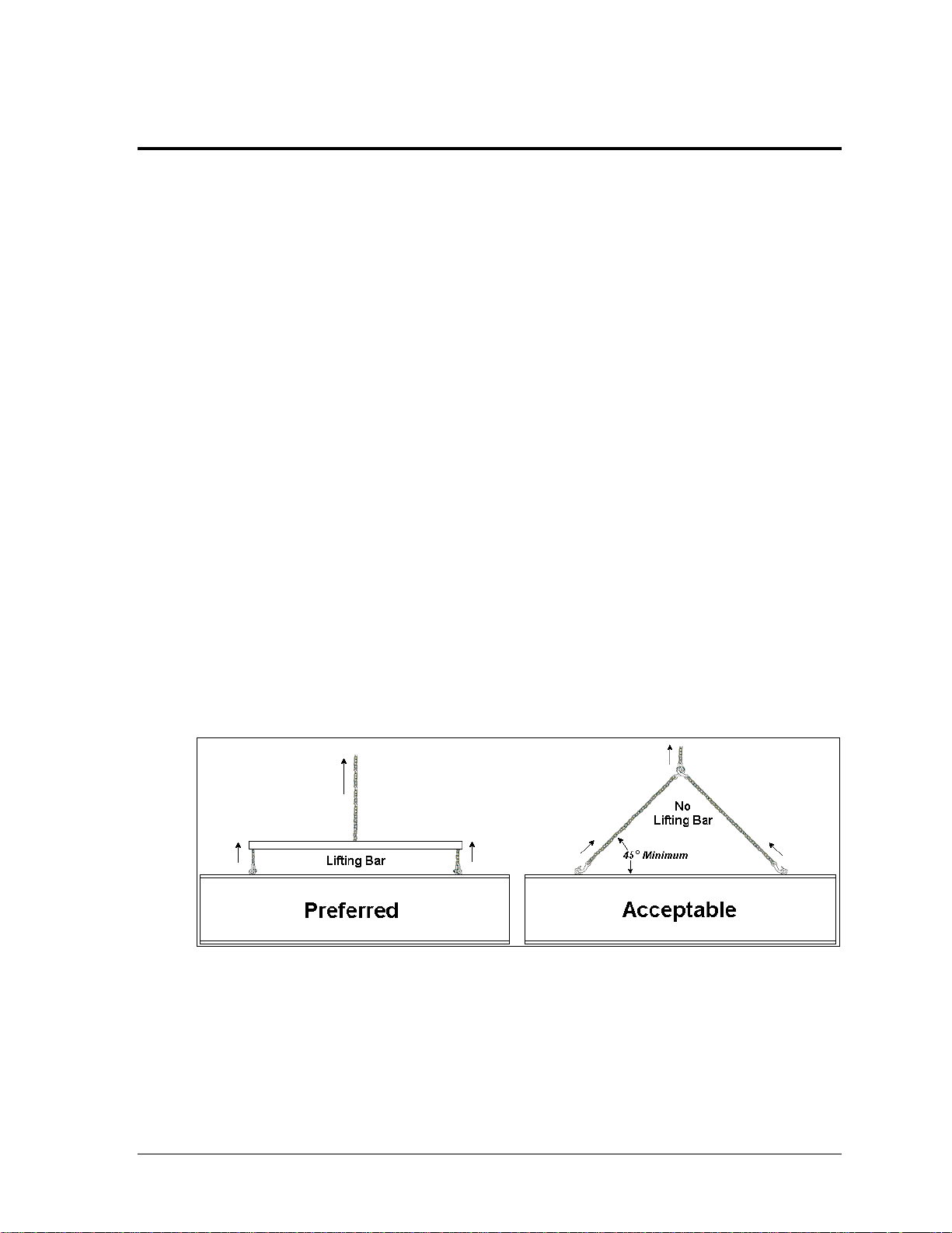
Figure 4: Lifting Methods
Section 3: Mechanical Installation
Mechanical installation consists of installing concrete footing and steel beams and mounting the
scoreboard and accompanying ad panels to the beams.
3.1 Footings & Beams
Drawing B-268714 in Appendix A shows the recommended number of beams and spacing
between them.
The column and footing size dimensions are to assist with estimating installation costs.
They are estimates only and are not intended for actual construction purposes. Be sure that
the installation complies with local building codes and is suitable for the particular soil and
wind conditions. The columns, footings, and all connection details must be designed and
certified by a professional engineer licensed to practice in the state of the installation.
Note: Daktronics does not assume any liability for any installation derived from the
information provided in this manual or installations designed and installed by others.
3.2 Lifting the Scoreboard
Larger scoreboard sections and message centers are shipped equipped with eyebolts used to
lift them. The eyebolts are located along the top of the cabinet for each scoreboard section.
Daktronics scoreboards use 1/2" and 5/8" shoulder-type eyebolts mounted to a 1/8" aluminum
plate or steel nut plate.
Daktronics strongly recommends using a spreader bar, or lifting bar, to lift the display.
Spreader bars ensure the force on the eyebolts remains straight up, minimizing lifting stress.
Figure 4 illustrates the preferred scoreboard lifting method on the left and an acceptable
alternative lifting method on the right. When lifting the display:
Use a spreader bar if possible.
Use every lifting point provided.
Mechanical Installation 7
Page 14

Figure 5: Eyebolt Plane Load
Cables and chains attached to the eyebolts and directly to
a center lifting point, as shown in the right-hand example
in Figure 4, can create a dangerous lateral force on the
eyebolts and may cause the eyebolts to fail. The smaller
the angle between the cable and the top of the display, the
lighter the sign must be to safely lift it. If this method
must be used, ensure a minimum angle between the chain
and scoreboard of at least 45 degrees.
Do NOT attempt to lift the display if the angle is less than
45 degrees. Exceeding load angles or weight limits could
cause the bolts in the scoreboard cabinet to buckle,
resulting in serious damage to the scoreboard or injury to
personnel. Also, loads should be applied directly in the
plane of the eyebolt as shown in Figure 5.
Note: Daktronics assumes no liability for damages resulting from incorrect setup or
lifting methods. Eyebolts are intended for lifting only. Do not attempt to permanently
support the display by the eyebolts.
If installers remove the eyebolts, plug the holes with bolts and the rubber washers that are
used with the eyebolts. Apply silicone or another waterproof sealant to the eyebolt openings.
Also inspect the top and sides of the display for any other holes or openings that may allow
moisture to enter the display and plug and seal those openings.
3.3 Scoreboard Mounting
In typical multi-section installations, the lower scoreboard is installed first and secured to the
support beams. The next section is then placed atop or above the lower section and attached
to the beams. There are cables extending from the top of the lower sections. Guide these
cables into the holes in the bottom of the upper sections for later connection.
Note: Refer to Section 4.5 for more information on the power/signal connections
between sections.
The CR-2004 scoreboard is typically mounted in one of two ways:
1) clamped to vertical beams using mounting angles and long, threaded rods
2) permanently welded to tubular horizontal supports.
8 Mechanical Installation
Page 15
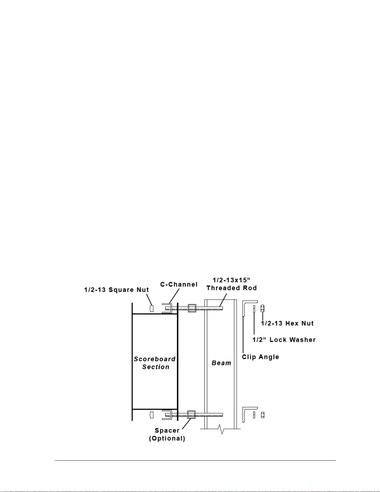
Figure 6: C-channel Mounting Method, Side View
Clamping to Verticals
An inverted channel mounting installation uses C-channels; clip angles; 1/2-13" threaded
rods; and 1/2" square nuts, hex nuts, lock washers, and optional spacers. Refer to Figure 6 and
Drawing A-55101 in Appendix A.
Mount the scoreboard as follows:
1. Place the C-channel against the upper and lower rear flanges of the scoreboard.
2. Use the width of the beam to determine the appropriate hole combination to use for
the bolts. The bolts should be kept as close to the beam as possible.
3. With the C-channel as a template, use a
rear flanges of the scoreboard cabinet where the bolts will pass through.
4. Place the
1
/2" square nuts inside the C-channel and thread the 1/2-13" rods through
the C-channel, rear flange of the scoreboard cabinet, and spacer (if used).
5. Lift the scoreboard into position with the bolts still in place. Position the scoreboard
at the front of the beams with the threaded rods extending from the rear flanges.
6. With the threaded rod straddling the beams, place mounting angles over each pair of
bolts and secure with 1/2" lock washers and hex nuts.
7. Make final adjustments in the positioning of the scoreboard.
8. Make sure that the threaded rods are perpendicular to the scoreboard, and tighten all
of the 1/2" hex nuts.
9
/16" bit to drill holes in the upper and lower
Mechanical Installation 9
Page 16
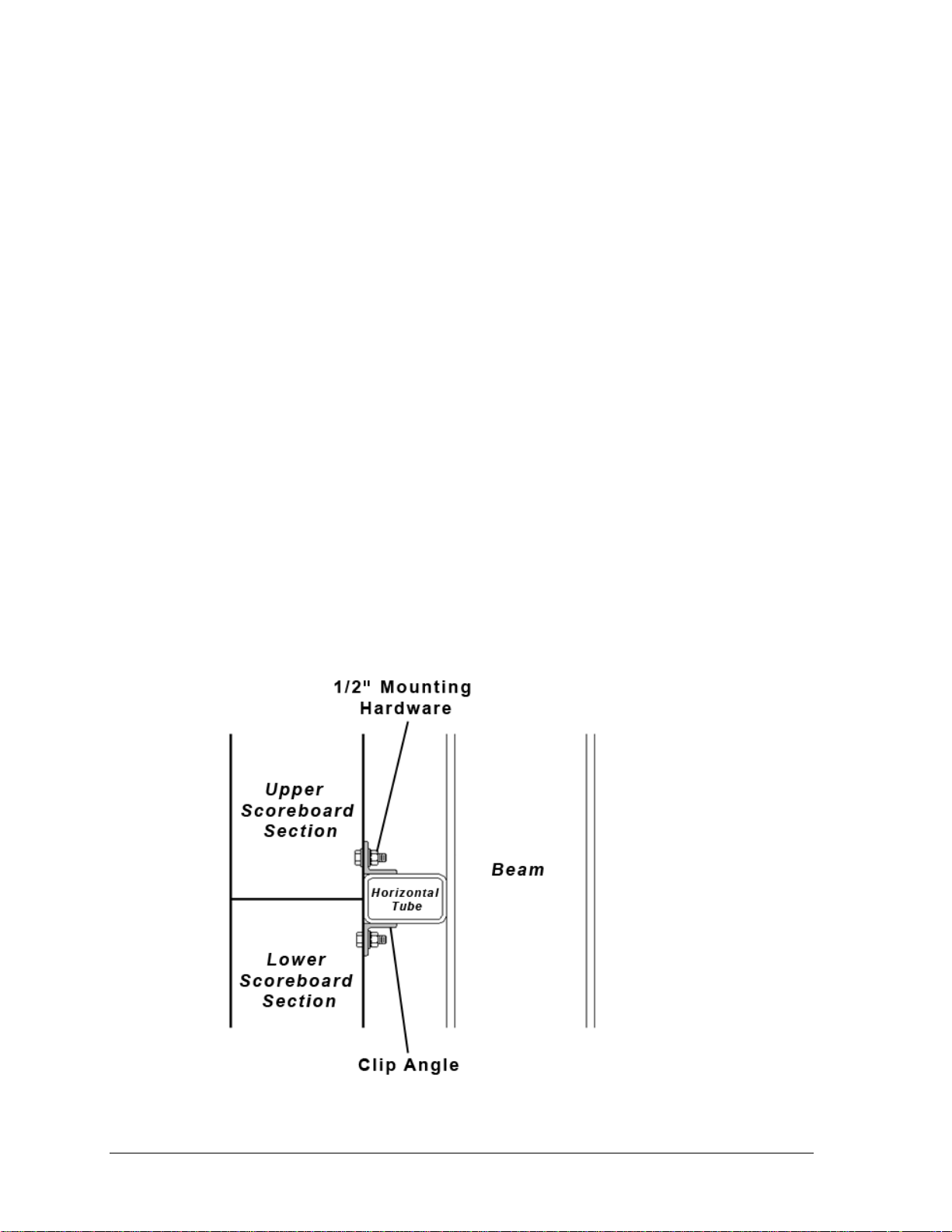
Figure 7: Scoreboard Mounting Detail, Side View
Welding to Horizontals
Steel clip angles are first bolted to the back of each scoreboard section. These clip angles are
then welded on three sides to a horizontal tube, which itself has been welded to the support
beams. Refer to Drawing B-268714 in Appendix A for suggested horizontal tube spacing.
Figure 7 and Drawing A-83301 illustrate the mounting of the display to horizontal tubing.
1. Visually check the display structure before beginning the installation process.
Ensure that the structure will provide a straight and square mounting frame for
the scoreboard/display.
Check to ensure the mounting frame will not give way at unsupported points
after the scoreboard/display is mounted. If any problems are noted, take
corrective action immediately.
2. Bolt the clip angles to the rear of the scoreboard sections with ½" hardware.
Drawing B-238471 shows recommended clip angle locations. Refer to projectspecific shop drawings for exact locations of the clip angles.
3. Lift the display section into position. Refer to Section 3.2.
4. Adjust the clip angles as needed so that they are firmly against the horizontal tube.
During the installation of the first section, carefully monitor the horizontal and
vertical straightness of the display. If the mounting structure does not provide a
straight or square mounting surface, it will be necessary to place shims between the
display section and the mounting surface to ensure straightness.
5. Weld the three edges of each clip angle that are in contact with the horizontal tube.
10 Mechanical Installation
Page 17
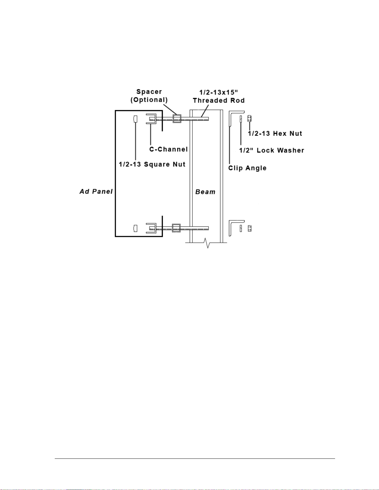
Figure 8: Ad Panel Mounting with C-channel, Side View
3.4 Ad Panel Mounting
The installation uses C-channels; clip angles; 1/2-13" threaded rods; and 1/2" square nuts, hex
nuts, lock washers, and optional spacers similar to the clamping mounting method above.
Refer to Figure 8 and Drawing A-52187 in Appendix A.
Mount the ad panel(s) as follows:
1. Use the width of the beam to determine which hole combination to use for the bolts.
Be sure to keep the bolts as close to the beam as possible.
2. Using the clip angle as a template, use a
9
/16" bit to drill holes in the upper and lower
rear flange of the ad panel where the C-channel supports will be placed.
3. Position the C-channel inside the ad panel cabinet along the upper and lower rear
flanges as shown in Figure 8.
4. Place
1
/2" square nuts inside the channel and thread the 1/2-13" rods through the
C-channel, rear flange of the ad panel, and spacer (if used).
5. Lift the ad panel into position with the rods still in place.
6. With the threaded rod straddling the beams, place mounting angles over the ends of
each pair of bolts and secure with 1/2" lock washers and hex nuts.
7. Make final adjustments in the positioning of the ad panel.
8. Make sure that the threaded rods are perpendicular to the ad panel, and tighten all of
the 1/2" hex nuts.
Some ad panels have back sheets that must be removed before the display can be installed.
After marking and drilling holes in the upper and lower rear flanges of the ad panel, remove
the back sheets above and below the hole locations. Position the C-channel inside the cabinet
and attach the square nuts to the threaded rods as described above. Be sure to replace the
back sheets after placing the square nuts inside the channel and threading the rods through
the holes in both the upper and lower rear flanges.
Mechanical Installation 11
Page 18

3.5 Scoreboard Protective Devices
Daktronics makes optional protective devices, including screens and netting, to help prevent
damage to the scoreboard due to normal ball impacts.
Note: Some users install devices to protect the scoreboard from projectiles. Scoreboard
protection devices not provided by Daktronics must be approved by Daktronics prior to
installation. Failure to follow this approval procedure will void the scoreboard warranty.
12 Mechanical Installation
Page 19
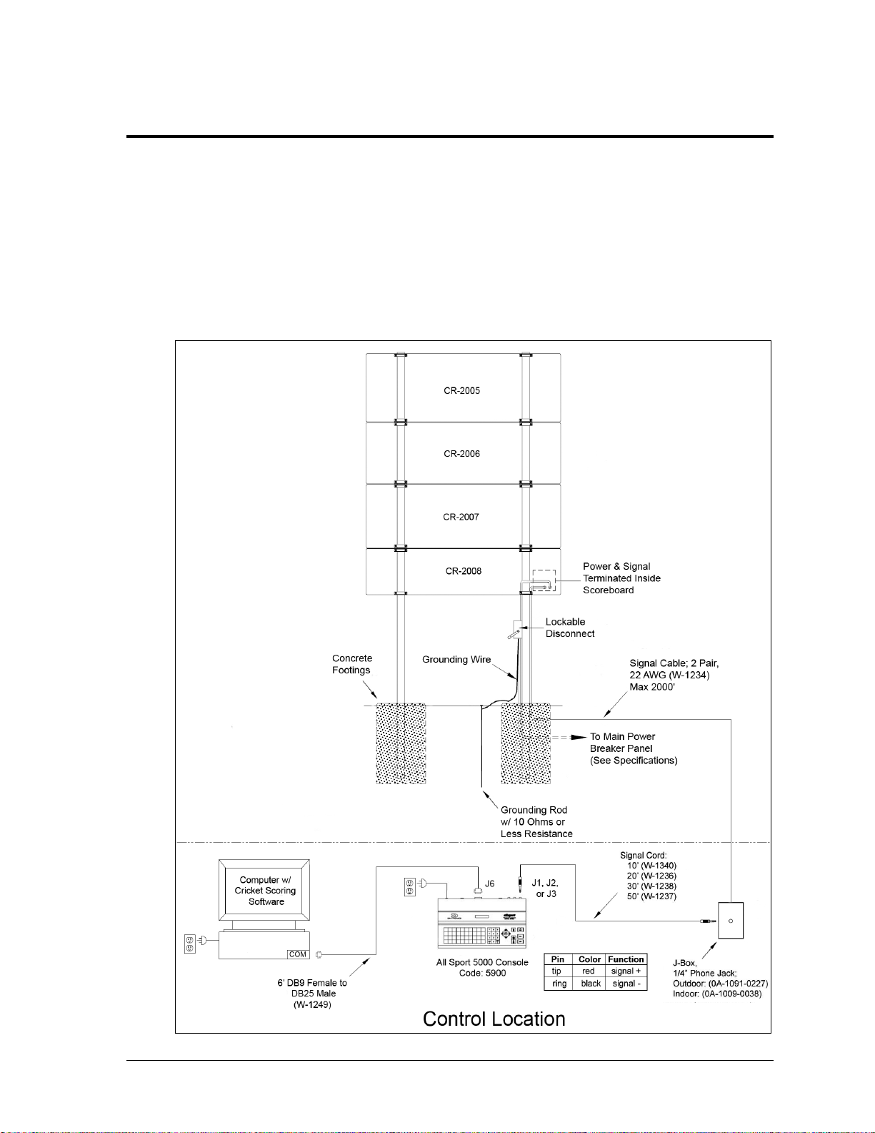
Figure 9: Wired Installation
Section 4: Electrical Installation
CAUTION: Only qualified individuals should terminate power and signal cable and access the
electrical components of the display and its associated equipment. It is the responsibility of the
electrical contractor to ensure that all electrical work meets or exceeds local and national codes.
Daktronics engineering staff must approve all changes or the warranty will be void.
4.1 Installation Overview
The diagram shown in Figure 9 illustrates a typical wired setup between a multi-section
cricket scoreboard and control system. Daktronics part numbers are shown in parentheses.
Electrical Installation 13
Page 20
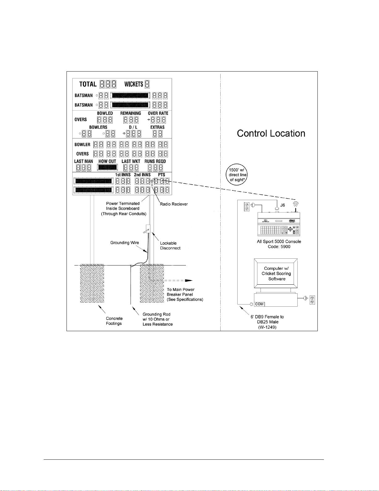
Figure 10: Wireless Installation
The diagram shown in Figure 10 illustrates a typical wireless setup between a multi-section
cricket scoreboard and control system. Daktronics part numbers are shown in parentheses.
All Sport Backup
If the scoring computer becomes inoperable, the All Sport 5000 can be used as a temporary
backup by changing the sport code to 5590.
Note: When operating the CR-2004 directly from the All Sport 5000 controller,
the following information cannot be entered and will not display:
BOWLED, REMAINING, & OVER RATE
D/L
BOWLER & OVERS 1-6
HOW OUT
1st INNS, 2nd INNS, & PTS for both teams
Both team names
14 Electrical Installation
Page 21

4.2 Power
Correct power installation is imperative for proper display operation. The subsections that
follow give details of display power installation. Only qualified individuals should attempt to
complete the electrical installation; untrained personnel should not attempt to install these
displays or any of the electrical components. Improper installation could result in serious
damage to the equipment or injury to personnel.
The scoreboards in this manual require a dedicated 240 V or 120 V circuit for incoming power
(refer to the Specifications in Section 2).
WARNING: It is critical that 120 V scoreboard circuits be fused at 15 A and that all
conductors used must be designed to pass a 15 A current in normal operation. For 240 V
scoreboards, consult local electrical codes. Failure to meet wiring and overcurrent
protection device requirements will void the scoreboard warranty.
Grounding
The display must be properly grounded according to local and national codes or the warranty
will be void. Proper grounding is necessary for reliable equipment operation and protects the
equipment from damaging destructive disturbances and lightning.
Daktronics recommends a resistance-to-ground of 10 ohms or less. The electrical contractor
performing the electrical installation can verify ground resistance. Daktronics Sales and
Service personnel can also provide this service.
The display system must be earth-ground. The material for an earth-ground electrode differs
from region to region and may vary according to conditions present at the site. Consult local
and national electrical codes.
Daktronics does not recommend using the support structure as an earth-ground electrode;
concrete, primer, corrosion, and other factors make the support structure a poor ground.
Note: The support structure may be used as an earth-ground electrode only if designed to do
so. A qualified inspector must approve the support structure and grounding methods.
There are two types of power installation: installation with ground and neutral conductors
provided, and installation with only a neutral conductor provided. These two power
installations differ slightly, as described in the following paragraphs:
Installation with Ground and Neutral Conductors Provided
For this type of installation, the power circuit must contain an isolated earth-ground
conductor. In this circumstance, do not connect neutral to ground at the disconnect or at the
display as this would violate electrical codes and void the warranty.
Use a disconnect so that all ungrounded lines can be disconnected. The National Electrical
Code requires the use of a lockable power disconnect within sight of or at the display.
Electrical Installation 15
Page 22

Figure 11: Power Warning Label
Installation with Only a Neutral Conductor Provided
Installations where no grounding conductor is provided must comply with Article 250-32 of
the National Electrical Code. If the installation in question meets all of the requirements of
Article 250-32, the following guidelines must be observed:
Connect the grounding electrode cable at the local disconnect, never at the display
driver/power enclosure.
Use a disconnect that opens all of the ungrounded phase conductors.
Connection
Power cabling is routed into the scoreboard from the rear through plastic plugs for conduit
connection. If no conduit knockouts are available, installers will have to drill holes into the
back sheet of the scoreboard to allow entrance of power wires.
All power wiring terminates at the enclosure shown in Figure 12, located in the lower-right
corner of the scoreboard (when viewed from the front). Refer to Drawing A-327249 in
Appendix A for precise power termination location.
1. Route the power cables via conduit into rear of
scoreboard.
2. Look for a warning label similar to Figure 11 to
locate the appropriate access panel to the power
breaker enclosure.
3. Loosen the screws or latches to open the access panel.
4. Route the power cables up through the bottom of the power enclosure.
5. Use a Philips screwdriver to loosen the two screws, and then lift the enclosure cover
up and off the keyholes.
6. Connect the power cables as follows:
Neutral (white) wire to NEUT.
Live wire to LINE 1 (black)
Live wire to LINE 2 (red) – 120 V installations only
Ground wire (green/yellow) to the grounding buss bar, E41
7. Reattach the metal enclosure cover and secure the access panel.
Note: If a power receptacle is needed to operate the control console at the scoreboard for
troubleshooting, Daktronics recommends that an installation electrician provides a 240 or
120 V outlet close to the disconnect box specifically for this purpose.
16 Electrical Installation
Page 23
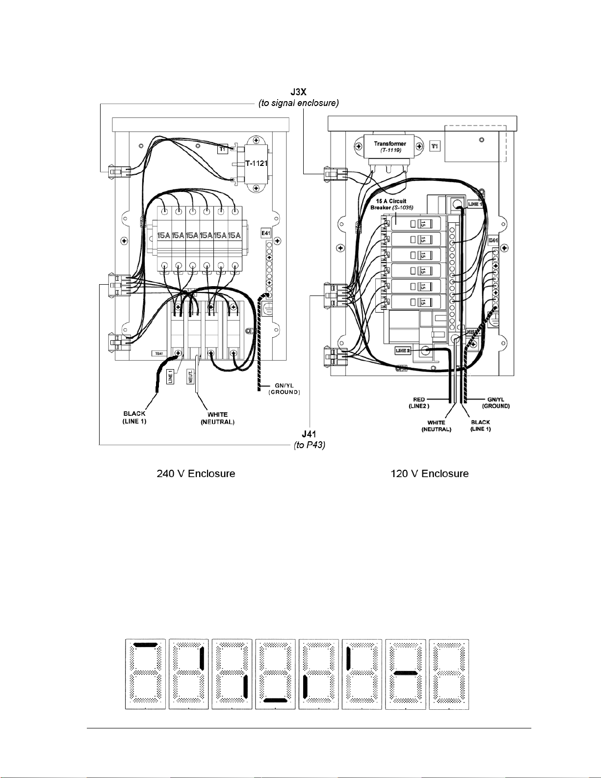
Figure 12: Power Enclosures w/ Covers Removed (240 V & 120 V)
Figure 13: Digit Segment POST
4.3 Power-On Self-Test (POST)
The scoreboard performs a self-test each time that power is turned on and the control console
is powered off or not attached to the scoreboard. If the control console is attached and
powered on, the self-test does not run, and data from the control console is displayed on the
scoreboard after a brief period of time. Each scoreboard self-test pattern will vary depending
on the scoreboard model, the number of drivers and types of digits. Figure 13 shows an
example of the LED bar test pattern that each digit performs.
Electrical Installation 17
Page 24
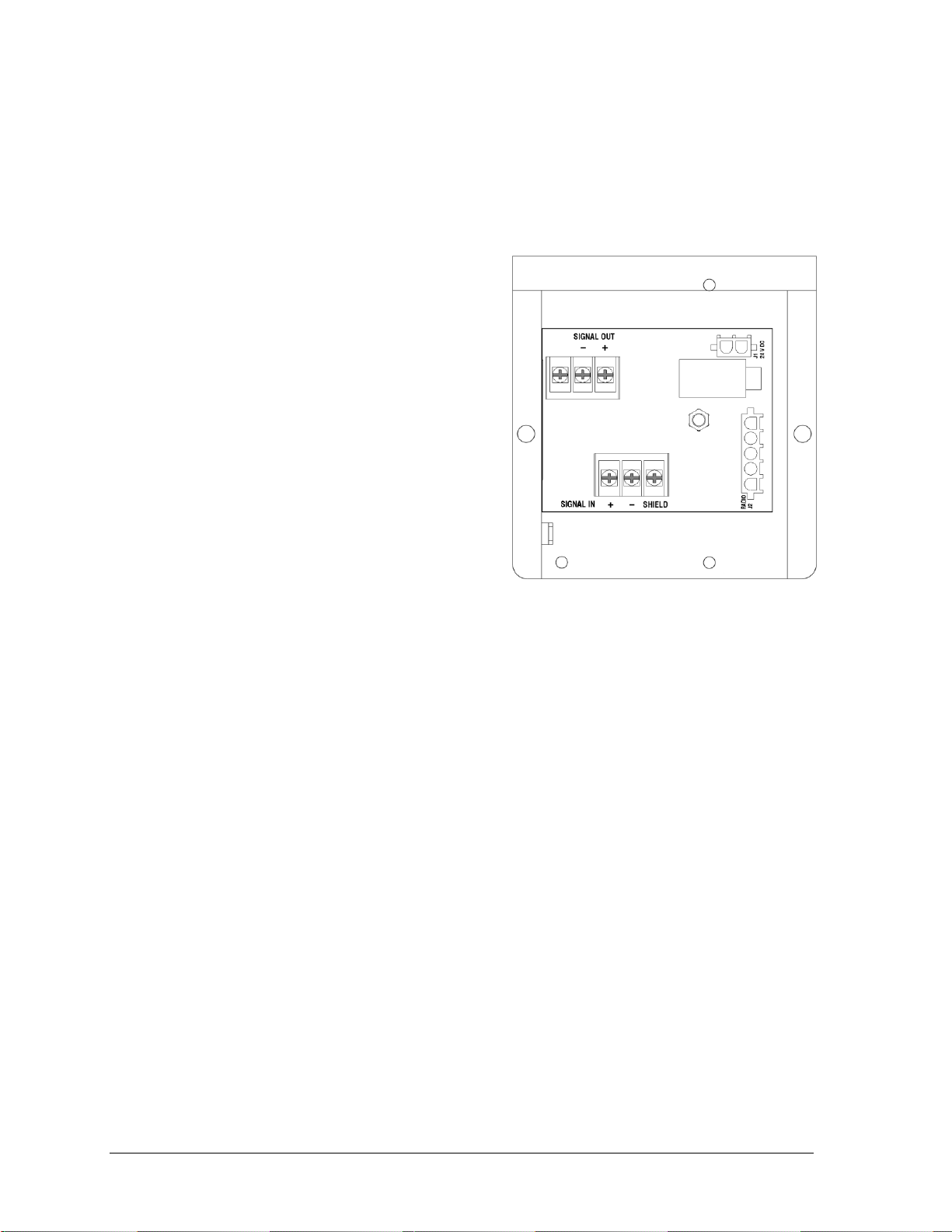
Figure 14: Signal Enclosure w/ Cover Removed
Radio Settings
If a radio receiver is installed, the radio Broadcast and Channel settings will be displayed in
on the scoreboard during the POST. These values must match the settings in the control
console (refer to the manual listed in Section 1.4). Refer to Section 5.6 for more information
on radio installations.
4.4 Signal Connection
Signal cabling is routed into the scoreboard
from the rear through plastic plugs for conduit
connection. If no conduit knockouts are
available, installers will have to drill holes into
the back sheet of the scoreboard to allow
entrance of power wires. Note that systems
with radio control do not require external
signal wiring to the display.
All signal wiring terminates at the enclosure
shown in Figure 14, located in the lower-right
corner of the scoreboard (when viewed from
the front). Refer to Drawing A-327249 in
Appendix A for precise signal termination
location.
1. Route the signal cables via conduit into
rear of scoreboard.
2. Look for a warning label similar to Figure 11 to locate the appropriate access panel
to the signal enclosure.
3. Loosen the screws or latches to open the access panel.
4. Route the signal cables up through the bottom of the signal enclosure.
5. Use a Philips screwdriver to loosen the two screws, and then lift the enclosure cover
up and off the keyholes.
6. At the SIGNAL IN terminal block, connect the signal cables as follows:
Red signal wire to positive (+) terminal
Black signal wire to negative (-) terminal
Silver wire to SHIELD terminal
7. Reattach the metal enclosure cover and secure the access panel.
8. At the control location, connect a 9-pin female to 25-pin male cable (Daktronics part #
W-1249) between the J6 jack on the back of the All Sport 5000 and an available serial
(COM) port on the cricket scoring computer.
Note: Refer to Appendix B for more information on setting up the TCS software.
9. For wired setups, also connect a signal cord from the J-box into jack J1, J2, or J3 on the
back of the All Sport 5000 controller.
For signal cable, Daktronics recommends, as a minimum, single-pair, shielded cable, 22 AWG
(Daktronics part number W-1077). Two-pair shielded cable (part W-1234) is preferred.
18 Electrical Installation
Page 25

Fiber Optic
Another common signal communication method is fiber optic cabling. A minimum cabling of
multi-mode, 62.5/125 um, and 2-core fiber cable is recommended (Daktronics part number
W-1242). In such installations, the signal enclosure shown in Figure 14 will be replaced by a
fiber J-box. This method also requires a signal converter between the All Sport console‟s
scoreboard output and the fiber optic cable (not provided by Daktronics).
4.5 Power/Signal Connections Between Sections
Refer to Drawing B-236615 in Appendix A for exact driver and power/signal interconnect
cable locations.
1. On the lowest scoreboard section, open the appropriate access panel to locate the
bundle of interconnect cable coming from the driver.
Note: Additional panels may be opened for easier access when routing the cable.
2. Route the interconnect cable through the hole in the top of the lower cabinet up into
the hole in the bottom of the upper cabinet, and connect the J43 jack to the mating P43
plug coming off of one of the drivers.
3. Repeat steps 1-2 to connect the remaining scoreboard sections.
4.6 Lightning Protection
The use of a disconnect near the scoreboard to completely cut all current-carrying lines
significantly protects the circuits against lightning damage. In order for this system to
provide protection, the power must be disconnected when the scoreboard is not in use.
The control console should also be disconnected from power and from the signal junction box
when the system is not in use. The same surges that may damage the scoreboard‟s driver can
also damage the console‟s circuitry.
Electrical Installation 19
Page 26

Page 27
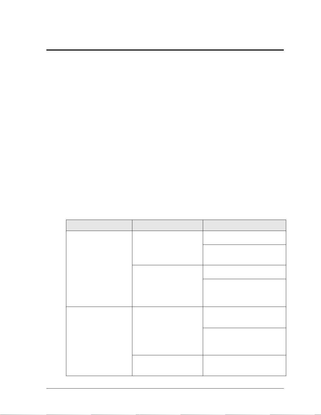
Problem
Possible Cause
Solution/Items to Check
Scoreboard doesn’t light
and console doesn’t work
No power to the scoreboard
Check that the main circuit breaker
for the scoreboard is on.
Check that the scoreboard is
receiving the correct 240 or 120 V
AC power (see Section 2).
No power to console
Ensure the console is plugged into a
240 or 120 V AC power supply.
Swap the console with one known to
work correctly, and enter the proper
sport code and/or radio settings to
test. Replace console if necessary.
Scoreboard digits don’t light,
but console works
No wired signal from console
Check that the scoreboard is
receiving the correct 240 or 120 V
AC power (see Section 2).
Check that the red DS2 LED on the
driver lights up when sending
commands from the computer or
control console (see Section 5.5).
No radio signal from console
Cycle power to the scoreboard and
watch for radio receiver broadcast/
channel settings (see Section 5.6).
Section 5: Scoreboard Troubleshooting
IMPORTANT NOTES:
1. Always disconnect power before doing any repair work on the scoreboard.
2. Permit only qualified service personnel to access internal display electronics.
3. Disconnect power when not using the scoreboard.
For assistance in the maintenance of team name message centers (TNMCs) or other optional
scoreboard message centers, refer to Section 6 or the service manual that accompanies those units.
5.1 Troubleshooting Table
The table below lists potential problems with the scoreboard and indicates possible causes
and corrective actions. This list does not include every symptom that may be encountered,
but it does present several of the most common situations that may occur.
Many of the solutions offered below provide references to other sections within this manual
or to supplemental product manuals with further detail on how to fix the problem.
If a problem occurs that is not listed or that cannot be resolved using the solutions in the
following table, contact Daktronics using the information provided in Section 5.10.
Scoreboard Troubleshooting 21
Page 28

Problem
Possible Cause
Solution/Items to Check
Check that the green POWER and
amber RADIO IN RANGE indicators
on the radio receiver in the
scoreboard light up when the control
console is powered on (see Section
5.6). Keep the console between 20
to 1500 feet from the scoreboard.
Move the console 20-30 feet from
the scoreboard and test again.
Verify that both the console and
scoreboard antennae are securely
tightened and in a vertical position.
Replace the radio receiver.
No signal to driver
Check that the scoreboard is
receiving the correct 240 or 120 V
AC power (see Section 2).
Check that the red DS2 LED on the
driver lights up when sending
commands from the control console
(see Section 5.5).
Swap the driver with one known to
work correctly and with the same
part number to verify the problem.
Replace if necessary (Section 5.5).
No power to driver
Check that the green DS1 LED on
the driver is always lit up when the
scoreboard is powered on
(see Section 5.5).
Scoreboard digits light, but
not in the correct order
Incorrect sport code
Ensure the correct sport code is
being used for the scoreboard
model. Refer to the operation
manual for the console being used
(see Section 1.4).
Incorrect driver address
Check that the scoreboard driver(s)
are set to the correct address(es)
(see Section 5.5)
Scoreboard digits light,
console works, but no
display on scoreboard
No wired signal from console
(See solution on previous page)
No radio signal from console
(See solution on previous page)
Bad/damaged field wiring
Check that the red DS2 LED on the
driver lights up when sending
commands from the control console
(see Section 5.5)
Scoreboard works, but some
LEDs always stay on
Short in digit or indicator circuit
Swap the digit or indicator with one
known to work correctly to verify the
problem. Replace if necessary (see
Sections 5.4).
22 Scoreboard Troubleshooting
Page 29

Problem
Possible Cause
Solution/Items to Check
Scoreboard works, but some
LEDs do not light or they
blink
Bad connection
Verify the Mate-N-Lok connector on
the back of the digit circuit board is
secure (see Section 5.2).
Verify power/signal interconnect(s)
between scoreboard sections
properly connected
(see Section 4.5)
Bad digit or driver
Swap the digit/driver with one known
to work correctly to verify the
problem. Replace if necessary (see
Sections 5.4 for digits or
Section 5.5 for drivers).
Scoreboard works, but some
digits do not light
Bad digit or driver
(see solution above)
Incorrect sport code
(see solution on previous page)
Incorrect driver address
(see solution on previous page)
Wrong console controlling
scoreboard
Another console’s radio signal could
be transmitting to the scoreboard.
An example would be football and
baseball scoreboards that are within
1500 feet of each other
(see Section 5.6).
Radio interference
There may be other radio
transmissions in the area that
overpower the console. If it is not
possible to disable the interfering
device, It may be necessary to run a
wired signal connection instead.
Figure 15: LED Digit Panel
5.2 Component Access
All internal electronic components are
reached by opening an access door or a
digit panel on the display.
Digit panels are held in place on the
scoreboard face by an offset flange across
the top and by screws at the bottom, as
shown in Figure 15.
To open a digit panel:
Scoreboard Troubleshooting 23
1. Hold the digit panel in place by
2. Carefully lift the panel away from
putting hand pressure on it and
remove the holding screws.
the scoreboard, sliding it out and
down.
Page 30

Figure 16: Digit Assembly
Note: If the panel is not held in place when the screws are removed, it could drop
and possibly damage LEDs or the digit harness.
With a non-digit access panel, simply remove the top, side and bottom screws holding it in
place. Some panels are hinged and swing open when the screws are removed or loosened.
Rear access panels can be lifted up and out over the screws through keyholes.
Note: When closing the access panel, make sure all latches/screws are holding the door
firmly in place to prevent moisture and debris from entering the scoreboard.
5.3 Component Locations
Refer to Drawing B-327249 in Appendix A. Drivers and power and signal components are
typically mounted inside the scoreboard behind a digit or access panel.
5.4 Replacing Digits & Indicators
LEDs are embedded in a circuit board that is mounted to the back of the digit panel, as
shown in Figure 16. Do not attempt to remove individual LEDs. In the case of a
malfunctioning LED or digit segment, replace the entire circuit board.
To replace a digit or indicator circuit board:
1. Open the digit panel as described
in Section 5.2.
2. Disconnect the power/signal plug
from the back of the circuit board
by squeezing together the locking
tabs and pulling the connector free.
3. Use a
4. Position a new circuit board over
5. Tighten the nuts.
6. Reconnect the power/signal
7. Close and secure the digit panel, then power up and test the scoreboard to see if
9
/32" nut driver to remove the
nuts securing the circuit board to
the inside of the panel, and then lift
it off the standoff studs.
the studs, making sure the rubber
side of the rubber-backed spacer is
facing the circuit board.
connector.
Note: This is a keyed connector and it will attach in one way only. Do not attempt to
force the connection.
changing the digit or indicator has resolved the problem.
24 Scoreboard Troubleshooting
Page 31

Figure 17: Driver Enclosure Location & Components
5.5 LED Drivers
The LED drivers perform the task of switching digits on and off within the scoreboard.
LED drivers are located inside of a driver enclosure. Refer to Figure 17 to view the location
and components of a driver enclosure.
Scoreboard Troubleshooting 25
Page 32

LED
Color
Function
Operation
Summary
DS1
Green
Power
Steady on
DS1 will be on and steady to
indicate the driver has power.
DS2
Red
Signal RX
Steady on
or blinking
DS2 will be on or blinking when the
driver is receiving a signal and off
when there is no signal.
DS3
Amber
Status
Blinking
DS3 will be blinking at one second
intervals to indicate the driver is
running.
Figure 18: Driver Status Indicators
When troubleshooting driver problems, three LEDs labeled DS1, DS2, and DS3 in Figure 18,
provide the following diagnostic information:
Note: While it is necessary to have the scoreboard powered on to check the LED
indicators, always disconnect scoreboard power before servicing.
Replacing a Driver
1. Open a digit or access panel as described in Section 5.2.
2. Remove the metal cover from the driver enclosure.
3. Disconnect all connectors from the driver by squeezing together the locking tabs and
4. Remove the screws or nuts securing the driver to the inside of the enclosure.
5. Carefully lift the driver from the display and place it on a clean, flat surface.
6. Position a new driver over the screws and tighten the nuts.
7. Reconnect all power/signal connectors.
26 Scoreboard Troubleshooting
pulling the connectors free.
Note: It may be helpful to label the cables to know which cable goes to which
connector when reattaching the driver.
Note: The connectors are keyed and will attach in one way only. Do not attempt to
force the connections.
Page 33

Figure 19: Driver Address Dip Switch
8. Ensure the driver is set to the correct address (refer to Setting the Driver Address).
9. Close and secure the digit panel, then power up and test the scoreboard to see if
changing the driver has resolved the problem.
Setting the Driver Address
Since the same LED drivers can be used for many scoreboard models, each driver must be set
to receive the correct signal input, or address, for the model being used. Addresses are set
through the S1 dip switch on the driver (Figure 19) using a pen or small, pointed object.
Refer to the specifications table in Section 2 to determine the correct address setting of the
driver(s) in a particular scoreboard model and see Drawing A-290261 in Appendix A for
addressing information for driver addresses 1 – 128.
Another method of setting the driver address using the J19 address plug is available. This
address is set with jumper wires in a 12-pin plug which mates with a jack on the driver. Refer
to Drawing A-115078 for a listing of the wire/pin connections for driver addresses 1 – 128.
When using an address plug, it will not be possible to set the address with the S1 dip switch.
5.6 Radio Connections
To determine the settings for radio connections between the scoreboard and control console:
1. Cycle power to the scoreboard.
2. After approximately seven seconds, the radio settings will be displayed. The first
values are the broadcast settings (“b1”), and the second are the channel settings
(“C1”). These values must match the settings within the console.
Note: If these settings do not appear, the radio receiver(s) may need to be
repaired/replaced.
To make sure the current radio settings match the receiver in the scoreboard, refer to the
operation manual of the particular control console being used (see Section 1.4).
Scoreboard Troubleshooting 27
Page 34

Figure 20: Radio Receiver w/ Cover
Figure 21: Radio Receiver w/o Cover
Radio Interference
If it has been determined that a nearby scoreboard‟s radio signal is interfering, the broadcast
and channel settings of the radio receiver inside the scoreboard(s) must be changed.
For more information, refer to the Gen V Radio Installation Manual ED-13831, available
online at www.daktronics.com/manuals.
1. To locate the radio receiver, look for the small black antenna sticking out the front of
the scoreboard.
2. Open the access panel to which the receiver is
attached as described in Section 5.2.
3. The radio receiver has a plastic cover. Three status
indicator LEDs are visible (Figure 20).
Note: While it is necessary to have the scoreboard
powered on to check the LED indicators, always
disconnect scoreboard power before servicing.
4. Remove the four screws using a #2 Philips
screwdriver and lift off the cover.
5. Inside the receiver are a channel switch (S1) and
two broadcast jacks (J4, J5) with a jumper.
Figure 21 shows the different configurations for the small jumper wire that sets the
radio broadcast (BCAST) mode. Move the jumper wire to the desired broadcast
location.
6. Use a small flathead screwdriver to set the S1 switch to the desired channel (1-8).
7. Screw the cover back on and securely close the access panel.
8. Enter the correct sport code and new radio settings into the console to test the radio
control (refer to the appropriate scoreboard controller manual).
28 Scoreboard Troubleshooting
Page 35

Model
Schematic Drawing #
CR-2005
B-236704
CR-2006
B-236733
CR-2007
B-235958
CR-2008
B-236727
Description
Location
Daktronics Part #
J-Box, 1/4" phone, Indoor
Signal
0A-1009-0038
J-Box, 1/4" phone, outdoor
Signal
0A-1091-0227
Signal surge board
Driver enclosure
0P-1110-0011
Digit, 15", 7-seg outdoor LED, red
Scoreboard
0P-1192-0200
Digit, 18", 7-seg outdoor LED, red
Scoreboard
0P-1192-0202
Digit, 15", 7-seg outdoor LED, amber
Scoreboard
0P-1192-0214
Digit, 18", 7-seg outdoor LED, amber
Scoreboard
0P-1192-0216
Indicator; 4" circular, red
Scoreboard
0P-1192-0244
Indicator; 4" circular, amber
Scoreboard
0P-1192-0245
Indicator; plus/minus, red
Scoreboard
0P-1192-0329
Indicator; plus/minus, amber
Scoreboard
0P-1192-0330
Driver, 16 col, outdoor, LED
Driver enclosure
0P-1192-0383
Power supply, 24 V, 150W (120 V AC)
Driver enclosure
A-1720
Power Supply; 24 V, 150W (240 V AC)
Driver enclosure
A-1733
Fan, 32 cfm, 24 V DC, 3.15 sq. in
Driver enclosure
B-1030
5.7 Segmentation and Digit Designation
In each digit, certain LEDs always go on and off together. These groupings of LEDs are called
segments. Drawing A-38532 in Appendix A details which connector pin is wired to each
digit segment and the wiring color code used throughout the display. Drawing B-327249 also
specifies the driver connectors controlling the digits. Numbers shown below each digit
indicate which driver and connector is wired to that digit.
5.8 Schematics
For advanced scoreboard troubleshooting and repair, it may be necessary to consult the
schematic drawings. These drawings, located in Appendix A, show detailed power and
signal wiring diagrams of internal display components such as drivers and transformers as
well as optional components like TNMCs and radio receivers. Use the following table to
determine the driver schematics for a particular model:
5.9 Replacement Parts
Refer to the following table for common Daktronics scoreboard replacement parts:
Scoreboard Troubleshooting 29
Page 36

Description
Location
Daktronics Part #
Plug, 1/4" phone
Signal
P-1003
Signal cord; 1/4" phone 20'
Signal
W-1236
Signal cord; 1/4" phone 50'
Signal
W-1237
Signal cord; 1/4" phone 30'
Signal
W-1238
Cable; RS-232, DB9F to DB25M, 6'
Signal
W-1249
Signal cord; 1/4" phone 10'
Signal
W-1340
Market Description
Customer Service Number
Schools (primary through community/junior colleges),
religious organizations, municipal clubs and community
centers
877-605-1115
Universities and professional sporting events, live events
for auditoriums and arenas
866-343-6018
5.10 Daktronics Exchange and Repair & Return Programs
Exchange Program
The Daktronics Exchange Program is a quick, economical service for replacing key
components in need of repair. If a component fails, Daktronics sends a replacement part to
the customer who, in turn, returns the failed component to Daktronics. This not only saves
money but also decreases equipment downtime. Customers who follow the program
guidelines explained below will receive this service.
Before Contacting Daktronics
Identify these important numbers:
Display Serial Number: _________________________________________________________
Display Model Number: ________________________________________________________
Contract Number: ______________________________________________________________
Date Installed: _________________________________________________________________
Daktronics Customer ID Number: ________________________________________________
To participate in the Exchange Program, follow these steps.
1. Call Daktronics Customer Service.
2. When the new exchange part is received, mail the old part to Daktronics.
If the replacement part fixes the problem, send in the problem part which is being
replaced.
a. Package the old part in the same shipping materials in which the replacement
part arrived.
b. Fill out and attach the enclosed UPS shipping document.
c. Ship the part to Daktronics.
30 Scoreboard Troubleshooting
Page 37

3. A charge will be made for the replacement part immediately, unless a qualifying
service agreement is in place. In most circumstances, the replacement part will be
invoiced at the time it is shipped.
If the failed part or replacement part is not returned to Daktronics within 3 weeks of
the ship date, Daktronics will assume that the customer is purchasing the
replacement part and will send an invoice for the value of the new sale part. If the
part or parts are returned within 2 weeks of the second invoice date, Daktronics will
credit the customer for the second invoice.
If after 2 weeks Daktronics has still not received the parts back, the customer must
pay the second invoice and will not be credited for the return of the failed part.
Daktronics reserves the right to refuse parts that have been damaged due to acts of
nature or causes other than normal wear and tear.
Repair & Return Program
For items not subject to exchange, Daktronics offers a Repair & Return Program. To send a
part for repair, follow these steps:
1. Call or fax Daktronics Customer Service:
Refer to the appropriate market number in the chart listed on the
previous page.
2. Receive a Return Materials Authorization (RMA) number before shipping.
This expedites repair of the part.
3. Package and pad the item carefully to prevent damage during shipment.
Electronic components, such as printed circuit boards, should be placed in an
antistatic bag before boxing. Daktronics does not recommend using packing „peanuts‟
when shipping.
4. Enclose:
name
address
phone number
the RMA number
a clear description of symptoms
Shipping Address
Daktronics Customer Service
RMA #
201 Daktronics Drive, Dock E
Brookings, SD 57006
Fax: 605-697-4444
Daktronics Warranty and Limitation of Liability
The Daktronics Warranty and Limitation of Liability is located in Appendix C. The Warranty
is independent of Extended Service agreements and is the authority in matters of service,
repair, and display operation.
Scoreboard Troubleshooting 31
Page 38

Page 39

Matrix Size
# of
modules
Pixel Spacing
Active Display Area
Weight*
8x32
4
34 mm (1.3")
10.6" x 42.5" (269 mm x 1080 mm)
40 lb (18 kg)
8x64
8
34 mm (1.3")
10.6" x 85.1" (269 mm x 2162 mm)
80 lb (36 kg)
Figure 22: Team Name Message Centers
Section 6: TNMC Troubleshooting & Maintenance
IMPORTANT NOTES:
1. Always disconnect scoreboard power before doing any repair/maintenance work on the
message centers.
2. Permit only qualified service personnel to access internal display electronics.
3. Disconnect power when not using the scoreboard.
6.1 Team Name Message Center System Overview
Team name message centers (TNMCs) use amber, red, or white LEDs to display team
names (home and guest) in place of vinyl captions (Figure 22). On the CR-2004, TNMCs
are also used to display the current BATSMEN names as well as a HOW OUT description.
TNMCs for the CR-2004 are available with two different pixel dimensions: 8x32 and 8x64.
Characters are shown on one line using single- or double-stroke fonts up to 10" (254 mm)
high for 34 mm TNMC units.
* TNMCs are typically installed in pairs; double this value to find the total added weight.
6.2 Initialization Information at Startup
Every time the display is powered up and there is no All Sport® signal present, the display
will run through an initialization process, during which it will test all LEDs and addresses.
First, the message center will display the proper address number.
If the entire display fails at startup, power may not be properly connected, or the address
setting may not be correct on the display driver. Check both in the event of a failure.
TNMC Troubleshooting & Maintenance 33
Page 40

Symptom/Condition
Possible Remedy
One or more LEDs on a single
module fails to light
Check/replace the ribbon cables on the module.
Replace the module. See Section 6.7.
One or more LEDs on a single
module fails to turn off
Check/replace the ribbon cables on module.
Replace the module. See Section 6.7.
A section of the display not
working; section extends all the
way to the right side of the display
Check/replace the ribbon cables running to the first module
that is not working.
Replace the first module/driver on the left side of the first
module that is not working. See Section 6.7.
Replace the second module that is not working.
See Section 6.7.
Replace the power supply assembly on the first module that
is not working. See Section 6.8.
One row of modules does not work
or is garbled
Replace the first module. See Section 6.7.
Replace the display driver. See Section 6.6.
A group of modules that share the
same power supply assembly fails
to work
Replace the power supply assembly. See Section 6.8.
Entire display fails to work
Check for proper line voltage into the power termination
panel.
Check/replace the ribbon cable from the display driver to the
modules.
Check the voltage settings on the power supplies.
Check/replace the signal cable to the driver.
Repair/replace the driver. See Section 6.6.
6.3 Display Troubleshooting Table
The table below lists potential problems with the display and indicates possible causes and
corrective actions. This list does not include every symptom that may be encountered, but it
does present several of the most common situations that may occur.
Many of the solutions offered below provide references to other sections within this manual
with further detail on how to fix the problem.
If a problem occurs that is not listed or that cannot be resolved using the solutions in the
following table, contact Daktronics using the information provided in Section 5.10.
34 TNMC Troubleshooting & Maintenance
Page 41

6.4 Power & Signal Summary
Reference Drawings:
Schematic, Amber TNMC, GEN IV ......................................................... Drawing A-252645
Schematic, Red TNMC, GEN IV ............................................................. Drawing A-252681
Schematic; 832 / 848 / 864 Red TNMC GEN IV, 240V ........................... Drawing A-294858
Schematic; 832 / 848 / 864 Amber GEN IV, 240V .................................. Drawing A-294919
Schematic, OD, 3500, 34mm TNMC, Red/Amb .................................... Drawing B-783938
Schematic, OD, 3500, 34mm TNMC, Wht .............................................. Drawing B-906385
Refer to Drawings B-783938 or B-906385 for detailed schematics about display power and
signal routing.
Note: For displays built before September 2009, refer instead to Drawings A-252645,
A-252681, A-294858, or A-294919.
Display signal routing can be summarized as follows:
1. Data from the All Sport
2. The signal travels to the driver/power enclosure through the J1 connector on the
signal surge arrestor card.
3. Data exits at J42 via current loop harness, and connects with P43 at the driver
assembly. A power/signal interconnect (ribbon cable) carries the signal to the first
module, and the signal relays from module to module, in daisy-chain style, until it
reaches the last module on the message center.
Display power routing can be summarized as follows:
1. Incoming power terminates at the terminal block in the scoreboard driver enclosure.
Using the same harness and J42-P43 connections as signal, power is then routed to
the display driver where it then travels to the power supply assembly.
2. From the power supply assembly, power is relayed to the first module, and then
from module to module.
3. The modules and display driver draw their power directly from the power supply
assemblies (3-12.5 VDC). The power supply voltage is set by a resistor loaded on the
module (via J4).
Note: In displays built before September 2009, modules draw their power directly
from the power supply assemblies (6.5 V for red LED modules, 9 V for amber), while
the display driver receives 16 V power from a transformer on the driver tray.
®
controller travels via cable harness into the scoreboard.
TNMC Troubleshooting & Maintenance 35
Page 42

Figure 23: 8x48-34 Display with Modules Removed
Figure 24: Discontinued 8x48-34mm Display with Modules Removed
6.5 Component Locations & Access
Reference Drawings:
Component Locations; 832/848/864 Red/Amb LED, TNMC, G4 ............ Drawing A-257029
Component Loc.; 34mm Red/Amb/Wht LED TNMC G4 .........................Drawing B-975100
Figure 23 illustrates the component locations of an 8x48-34mm display with all modules
removed. This layout will be similar for 8x32-34mm cabinets as well. The 8x64-34mm cabinets
require an additional power supply behind the sixth module. Refer to Drawing B-975100.
For Displays Built Before September 2009
Figure 24 illustrates the component locations of an older 8x48-34mm display, and this layout
will also be similar for 8x32-34mm and 8x64-34mm cabinets. Refer to Drawing A-257029.
Standard Daktronics outdoor LED scoreboards are typically front-accessible, but some
models may be ordered with rear service access. For that reason, Daktronics TNMCs have
been designed so that they may be accessed from both the front and rear.
36 TNMC Troubleshooting & Maintenance
Page 43

Figure 25: Module, Front View
Figure 26: Display Cabinet Rear Access
Front Access
1. Loosen the latch fasteners on the front
face the LED module using a 1/8" hex
wrench (or 7/32" nut driver for displays
installed prior to 11/29/05). One latch
fastener is centered below the top row of
pixels and one is centered above the
bottom row (Figure 25).
2. Turn each fastener a quarter-turn
counter-clockwise (if using a nut driver,
turn the top latch clockwise and the
bottom latch counterclockwise).
Note: Do not over turn the fastener!
Carefully remove the module from the face of the message center.
Rear Access
1. To access the internal components from the rear, remove the appropriate rear-access
panel from the display cabinet by loosening all four of the screws.
2. Slide the access panel sideways to the larger part of the keyhole and carefully lift it
off the display cabinet.
Note: Be careful when removing and handling the access panels as internal display
components may still be attached to them.
The display driver and primary power supply will always be located behind the first access
panel on the right, when viewing the display from behind. Any additional power supplies are
noted in the appropriate component location drawings.
Note: In displays built before September 2009, the display driver is located behind the first
access panel and the primary power supply is located behind the second access panel.
6.6 Display Drivers
Reference Drawings:
Address Table, 129 Through 255 ........................................................... Drawing A-115079
4 Column MASC LED Driver Specifications ........................................... Drawing A-166216
Address Table: Driver- MCAST G2- TNMC Switch ................................ Drawing A-328274
Specifications; Driver, MCAST, 4 Col ..................................................... Drawing A-793970
TNMC Troubleshooting & Maintenance 37
Page 44

Figure 27: 4 Column MCAST Driver
Figure 28: Control Assembly (4 Column MASC Driver)
The display driver receives signal from the control console via a signal surge arrestor card
and sends data to the modules. Refer to Section 6.4 for more information on signal routing.
The driver itself is detailed in Drawing A-793970 in Appendix A. Figure 27 illustrates some
of the primary jacks and switches on the 4 Column MCAST display driver.
The S2 DIP switch controls Home and Guest display. When the #5 switch is ON, the driver
sends guest team information to the display. In the opposite message center, the switch
would be set to OFF, and home information would be displayed.
The S2 DIP switch is also used to set the address (switches #1-4). With switches 1-4 off, the
address setting equals “221”. This is the address needed to display BATSMAN names. Team
names must be set to address “222”, and the HOW OUT display must be set to address “223”
with the #5 switch OFF (home). Refer to Drawing A-328274 in Appendix A for more
information on setting the driver address.
For Displays Built Before September 2009
The display driver receives signal from the control console via a signal surge arrestor card
and sends data to the modules. Refer to Section 6.4 for more information on signal routing.
The driver itself is detailed in Drawing A-166216 in Appendix A. Figure 28 illustrates a
display control assembly with a 4-column MASC driver.
38 TNMC Troubleshooting & Maintenance
Page 45

LED Name
Color
Illumination Summary
(CL) RX
Red
Steady on or blinking when the driver is receiving
signal and off when there is no signal
(CL) TX
Green
Steady on or blinking when the driver is
transmitting and off when there is no signal
Power
Green
Steady on to indicate the driver has power
Status
Amber
Blinking to indicate driver is running
Connectors J25 and J26 control Home and Guest displays. When the ribbon cable is plugged
into J25, the TNMC displays home team information. In the opposite message center, the
signal cable should be plugged into the J26 connector to display guest information.
J19 is the connector for the address plug. To display BATSMAN names, the display address
must be set to “221”. Team names must be set to address “222”, and the HOW OUT display
must be set to address “223” and plugged into J25. Refer to Drawing A-115079 in Appendix
A for more information on setting the driver address.
Diagnostic LEDs
The following table explains the functions of the primary diagnostic LEDs on the 4 Column
MASC/MCAST drivers:
Replacing a Driver
1. Access the internal components using the appropriate Front/Rear Access method
described in Section 6.5.
2. Disconnect all power and signal connectors from the driver by squeezing together the
locking tabs and pulling the connectors free.
Note: It may be helpful to label the cables to know which cable goes to which
connector when reattaching a driver.
3. Remove the four nuts holding the driver in place.
4. Position a new driver over the screws and tighten the nuts.
5. Reconnect all power/signal connectors.
6. Ensure the driver is set to the correct address.
7. Power up and test the scoreboard/display to see if changing the driver has resolved
the problem.
6.7 Modules
Each module assembly is made up of a module housing (containing LEDs and the driver) and
a louver assembly. Individual components such as louvers can be removed for service, but
Daktronics recommends that the module be kept intact and that the entire assembly be sent in
for repair or replacement.
TNMC Troubleshooting & Maintenance 39
Page 46

Figure 29: Module, Rear View
Replacing Modules
To replace a module from the front:
1. Follow the steps in the Front Access method described in Section 6.5.
2. Carefully disconnect all power and signal cables. It may be helpful to label the cables
to know which cable goes to which connector when reattaching a module.
3. Position a new module on the front of the display frame and reconnect all power and
signal cables.
4. Re-latch the fasteners.
5. Power up and test the scoreboard/display to see if changing the module has resolved
the problem.
To replace a module from the rear:
1. Follow the steps in the Rear Access method described in Section 6.5.
2. Use a 1/8" hex wrench or
(Figure 29). Turn each fastener a quarter-turn clockwise (if using a nut driver, turn
the top latch counter-clockwise and the bottom latch clockwise).
Note: Do not over turn the fastener!
3. While holding onto the module, push it out and turn it in such a manner (generally a
sideways, diagonal turn) that it can be pulled back through the frame opening.
4. Carefully disconnect all power and signal cables. It may be helpful to label the cables
to know which cable goes to which connector when reattaching a module.
5. Reconnect all power and signal cables to the new module and push it back through
and out the front of the display frame.
6. Re-latch the fasteners.
7. Power up and test the scoreboard/display to see if changing the module has resolved
the problem.
7
/32" nut driver to loosen the latch fastener assembly
40 TNMC Troubleshooting & Maintenance
Page 47

Weather-stripping
To ensure that the display is waterproof, weather-stripping has been installed around each
module. It is important that the weather-stripping is attached properly at all times, or water
may leak into the display and damage the components.
When installing a new module, take note of the following points:
The weather-stripping on the back edge of the module must be intact and in good
condition to prevent water from seeping into the display.
The module latches must be fully engaged to create a watertight seal around the edge
of the module. The module should be firmly seated against the display when the
latches are fully engaged.
6.8 Power Supplies
Power supply configurations will vary depending on the number and/or color of modules.
Replacing a Power Supply
To remove a power supply from the display:
1. Access the internal components using the appropriate Front/Rear Access method
described in Section 6.5.
2. Disconnect all the wires connected to the power supply.
3. Loosen the screw securing the power supply and slide it out of the display cabinet.
Note: In displays built before September 2009, use a 9/32" nut driver to remove the
hardware securing the power supply.
4. Fasten the new power supply in place and reconnect all wires.
6.9 Display Maintenance
Complete a yearly inspection to maintain safe and dependable display operation.
This inspection should address the following issues:
Loose Hardware: Verify that fasteners, such as bolts and rivets, have not come loose.
Check and tighten or replace fasteners as required.
Excessive Dust Buildup: It may be necessary to occasionally vacuum the inside of
the display cabinet to remove dust/dirt buildup that may interfere with airflow.
Water Intrusion – Water stain marks: Water can enter the display where weather-
stripping has come loose or deteriorated; where fasteners have come loose, allowing
gaps in the panels; or where moisture may be entering around hardware. Check
electronic components for corrosion.
Corrosion: Check the paint, and look for possible corrosion, especially at footings,
structural tie points, and ground rods and other types of grounding electrodes.
Note: If any of the preceding conditions are discovered, make the necessary repairs
or take corrective action immediately.
TNMC Troubleshooting & Maintenance 41
Page 48

Part Description
Part Number
Module; 8X8-34, Red
0A-1208-5005
Module; 8X8-34, Red (Sep 2009 – Nov 2010 only)
0A-1208-5002
Module; 8X8-34, Amber
0A-1208-5008
Module; 8X8-34, White
0A-1208-5004
Driver; MCAST, 4 Column
0P-1388-0201
Power Supply; 3-6.5V, 90-264V AC (all 34mm LED colors)
A-2307
Cable; 20 pos, Ribbon, 36"
W-1495
Cable; 20 pos, Ribbon, 18"
W-1387
Electrical contact lubricant (CaiLube®)
CH-1019
Part Description
Part Number
Ribbon Cable, 18" (module to module)
0A-1000-0015
Ribbon Cable, 30" (TNMC driver to first module)
0A-1000-0017
4-col MASC Driver
0P-1192-0068
Transformer; 115/230 V pri, 16 V sec @ 2 A
T-1063
Power Supply Assembly; Red TNMC
0A-1192-3160
Power Supply; 6.5V,15A, 85-264 V AC
A-1591
Power Supply Assembly; Amber TNMC
0A-1192-3161
Power Supply; 9V, 17A, 85-265 V AC
A-1633
Red 8x8 34mm Module Assembly
0A-1208-4004
Amber 8x8 34mm Module Assembly
0A-1208-4005
6.10 Replacement Parts List
The following tables contain TNMC components that may have to be replaced. Many of the
components within the display itself have attached part number labels.
For Displays Built Before September 2009
See Section 5.10 for information on Daktronics Exchange and Repair and Return program.
42 TNMC Troubleshooting & Maintenance
Page 49

Section 7: Additional Scoreboard Options
7.1 Radio Control
Radio control is an option for all Daktronics outdoor LED scoreboards. The system provides
scoreboard control via a 2.4 GHz, extra-high frequency FM signal.
The radio transmitter and receiver are not standard. This setup requires a control console
equipped with radio output as well as a radio receiver plugged into the power terminal block
in the driver/power enclosure and mounted internally to the front panel of the scoreboard.
For additional information about this option, contact a Daktronics representative; for
complete information on setting up radio communication control, refer to the Gen V Radio
Installation Manual (ED-13831), available online at www.daktronics.com/manuals.
Additional Scoreboard Options 43
Page 50

Page 51

Appendix A: Reference Drawings
Segmentation, 7 Segment Bar Digit ............................................................................ Drawing A-38532
Ad Panel Mounting ....................................................................................................... Drawing A-52187
Scoreboard Mounting .................................................................................................. Drawing A-55101
Steel Clip Angle Mounting ............................................................................................ Drawing A-83301
Address Table, 1 Through 128 .................................................................................. Drawing A-115078
Address Table, 129 Through 255 .............................................................................. Drawing A-115079
Schematic, Multipurpose LED DRVR ........................................................................ Drawing A-165028
4 Column MASC LED Driver Specifications .............................................................. Drawing A-166216
Schematic and Digit Designation: CR-2007 .............................................................. Drawing B-235958
Overall Layout; CR-2004, Multi-section ..................................................................... Drawing B-236615
Schematic and Digit Designation: CR-2005 .............................................................. Drawing B-236704
Schematic and Digit Designation: CR-2008 .............................................................. Drawing B-236727
Schematic and Digit Designation: CR-2006 .............................................................. Drawing B-236733
Clip DWG; CR-2004 .................................................................................................. Drawing B-238471
Schematic, Amber TNMC, GEN IV ............................................................................ Drawing A-252645
Schematic, Red TNMC, GEN IV ................................................................................ Drawing A-252681
Component Locations; 832/848/864 Red/Amb LED, TNMC, G4 .............................. Drawing A-257029
Shop DWG, CR-2004-11/-21, Clip Mtg ..................................................................... Drawing B-268714
Specifications; LED Driver IV, 16 Col ........................................................................ Drawing A-288137
Address Table 1; GEN IV Driver Address Dip Switch ................................................ Drawing A-290261
Schematic; 832 / 848 / 864 Red TNMC GEN IV, 240V ............................................. Drawing A-294858
Schematic; 832 / 848 / 864 Amber GEN IV, 240V ..................................................... Drawing A-294919
System Riser: Computer Controlled Criket ................................................................ Drawing B-326325
Component Location; CR-2004-11, -21, -12, -22 ...................................................... Drawing A-327249
Address Table: Driver- MCAST G2- TNMC Switch ................................................... Drawing A-328274
Schematic, OD, 3500, 34mm TNMC, Red/Amb ....................................................... Drawing B-783938
Specifications; Driver, MCAST, 4 Col ........................................................................ Drawing A-793970
Schematic, OD, 3500, 34mm TNMC, Wht ................................................................ Drawing B-906385
Component Loc.; 34mm Red/Amb/Wht LED TNMC G4 ........................................... Drawing B-975100
Reference Drawings 45
Page 52

Page 53

Page 54

Page 55

Page 56

Page 57

Page 58

Page 59

Page 60

Page 61

Page 62

Page 63

Page 64

Page 65

Page 66

Page 67

Page 68

Page 69

Page 70

Page 71

Page 72

Page 73

Page 74

Page 75

Page 76

Page 77

Page 78

Page 79

Page 80

Page 81

Page 82

Page 83

Appendix B: Supplemental Manuals
Quick Guide: Total Cricket Scorer (DD1420310)
Supplemental Manuals 47
Page 84

Page 85

Quick Guide: Total Cricket Scorer 1 of 2
201 Daktronics Drive, Brookings, SD 57006
Tel: 605-697-4036 or 888-325-7828 Fax: 605-697-4700
Website: www.daktronics.com
DD1420310 Rev 0
8/26/2008
Figure 1
Figure 2
DakMDP + Venus: the full Venus stream of data;
Activating a Scoreboard
In order to allow TCS to control
your scoreboard/display, you
must first enter the appropriate
registration keys.
1. Go to Help > Activate
Scoreboard.
2. On the Activate Scoreboard
window (Figure 1), type in the
Register Key and Serial Number.
Note: This information can be
requested via e-mail or over the internet. Be sure to provide
the Volume Number when making a request.
3. Click Activate.
uses “Code 27 Cricket Scoreboard.itf”
DakMDP + MiniFeed: a smaller stream of data that
can be used when Team Name Message Centers
(TNMCs) in a fixed digit board are matrix displays
instead of TNMCs; uses “Code 27 Cricket
Scoreboard (Limited).itf”
1. Go to Tools > Options.
2. Click the Scoreboard tab (Figure 2).
Note: The top Communications port is for the Multi-Drop Protocol
(MDP) to a fixed digit display, and the bottom Communications
Port 2 is used for Enhanced Real Time Data (ERTD) to matrix
display controllers.
3. Under Manufacturer, choose from:
4. Type in the correct Comm Port setting for the
communications ports as needed.
5. Click Apply and then OK when finished.
Page 86

Quick Guide: Total Cricket Scorer 2 of 2
201 Daktronics Drive, Brookings, SD 57006
Tel: 605-697-4036 or 888-325-7828 Fax: 605-697-4700
Website: www.daktronics.com
DD1420310 Rev 0
8/26/2008
Figure 3
Figure 4
After activating and configuring
the scoreboard, four new buttons
will become active on the main
toolbar (Figure 3).
Click the first button to
refresh all of the data
going to the external
scoreboard.
Click the second button to pause scoreboard updates.
Click the third button to select a graphic for the scoreboard if
applicable.
Click the fourth button for scoreboard brightness and
diagnostics (Figure 4).
o Use the slider to adjust the Brightness of the
scoreboard, or select Auto Dim.
o Select a Test Pattern to test the scoreboard
connection/performance.
o Click Apply and then OK when finished.
Page 87

Appendix C: Daktronics Warranty and Limitation
of Liability
Daktronics Warranty and Limitation of Liability 49
Page 88

Page 89

Copyright © Daktronics, Inc. SL-02374 Rev 10 02-Mar-2009 Page 1 of 2
DAKTRONICS
WARRANTY AND LIMITATION OF LIABILITY
This Warranty and Limitation of Liability (the “Warranty”) sets forth the warranty provided by Daktronics with respect to the Equipment. By accepting
delivery of the Equipment, Purchaser agrees to be bound by and accept these terms and conditions. All defined terms within the Warranty shall have the
same meaning and definition as provided elsewhere in the Agreement.
DAKTRONICS WILL ONLY BE OBLIGATED TO HONOR THE WARRANTY SET FORTH IN THESE TERMS AND CONDITIONS UPON RECEIPT OF FULL
PAYMENT FOR THE EQUIPMENT.
1. Warranty Coverage
2. Exclusion from Warranty Coverage
A. Daktronics warrants to the original end-user that the Equipment will be free from Defects (as defined below) in materials and
workmanship for a period of one (1) year (the “Warranty Period”). The warranty period shall commence on the earlier of: (i) four weeks from
the date that the equipment leaves Daktronics’ facility; or (ii) Substantial Completion as defined herein. The warranty period shall expire on the
first anniversary of the commencement date.
“Substantial Completion” means the operational availability of the Equipment to the Purchaser in accordance with the Equipment’s
specifications, without regard to punch-list items, or other non-substantial items which do not affect the operation of the Equipment.
B. Daktronics’ obligation under this Warranty is limited to, at Daktronics’ option, replacing or repairing, any Equipment or part thereof that is
found by Daktronics not to conform to the Equipment’s specifications. Unless otherwise directed by Daktronics, any defective part or
component shall be returned to Daktronics for repair or replacement. Daktronics may, at its option, provide on-site warranty service.
Daktronics shall have a reasonable period of time to make such replacements or repairs and all labor associated therewith shall be performed
during regular working hours. Regular working hours are Monday through Friday between 8:00 a.m. and 5:00 p.m. at the location where
labor is performed, excluding any holidays observed by either Purchaser or Daktronics.
C. Daktronics shall pay ground transportation charges for the return of any defective component of the Equipment. If returned Equipment is
repaired or replaced under the terms of this warranty, Daktronics will prepay ground transportation charges back to Purchaser; otherwise,
Purchaser shall pay transportation charges to return the Equipment back to the Purchaser. All returns must be pre-approved by Daktronics
before shipment. Daktronics shall not be obligated to pay freight for any unapproved return. Purchaser shall pay any upgraded or expedited
transportation charges.
D. Any replacement parts or Equipment will be new or serviceably used, comparable in function and performance to the original part or
Equipment, and warranted for the remainder of the Warranty Period. Purchasing additional parts or Equipment from the Seller does not
extend this Warranty Period.
E. Defects shall be defined as follows. With regard to the Equipment (excepting LEDs), a “Defect” shall refer to a material variance from the
design specifications that prohibit the Equipment from operating for its intended use. With respect to LEDs, “Defects” are defined as LED pixels
that cease to emit light. The limited warranty provided by Daktronics does not impose any duty or liability upon Daktronics for partial LED
pixel degradation. Nor does the limited warranty provide for the replacement or installation of communication methods including but not
limited to, wire, fiber optic cable, conduit, trenching, or for the purpose of overcoming local site interference radio equipment substitutions.
THIS LIMITED WARRANTY IS THE ONLY WARRANTY APPLICABLE TO THE EQUIPMENT AND REPLACES ALL OTHER WARRANTIES OR
CONDITIONS, EXPRESS OR IMPLIED, INCLUDING, BUT NOT LIMITED TO, THE IMPLIED WARRANTIES OR CONDITIONS OF
MERCHANTABILITY AND FITNESS FOR A PARTICULAR PURPOSE. SPECIFICALLY, EXCEPT AS PROVIDED HEREIN, THE SELLER UNDERTAKES
NO RESPONSIBILITY FOR THE QUALITY OF THE EQUIPMENT OR THAT THE EQUIPMENT WILL BE FIT FOR ANY PARTICULAR PURPOSE FOR
WHICH PURCHASER MAY BE BUYING THE EQUIPMENT. ANY IMPLIED WARRANTY IS LIMITED IN DURATION TO THE WARRANTY PERIOD.
NO ORAL OR WRITTEN INFORMATION, OR ADVICE GIVEN BY THE COMPANY, ITS AGENTS OR EMPLOYEES, SHALL CREATE A WARRANTY
OR IN ANY WAY INCREASE THE SCOPE OF THIS LIMITED WARRANTY.
THIS LIMITED WARRANTY IS NOT TRANSFERABLE.
The limited warranty provided by Daktronics does not impose any duty or liability upon Daktronics for:
A Any damage occurring, at any time, during shipment of Equipment unless otherwise provided for in the Agreement. When returning
Equipment to Daktronics for repair or replacement, Purchaser assumes all risk of loss or damage, and agrees to use any shipping containers
that might be provided by Daktronics and to ship the Equipment in the manner prescribed by Daktronics;
B. Any damage caused by the unauthorized adjustment, repair or service of the Equipment by anyone other than personnel of Daktronics or
its authorized repair agents;
C. Damage caused by the failure to provide a continuously suitable environment, including, but not limited to: (i) neglect or misuse, (ii) a
failure or sudden surge of electrical power, (iii) improper air conditioning or humidity control, or (iv) any other cause other than ordinary use;
Page 90

Copyright © Daktronics, Inc. SL-02374 Rev 10 02-Mar-2009 Page 2 of 2
D. Damage caused by fire, flood, earthquake, water, wind, lightning or other natural disaster, strike, inability to obtain materials or utilities,
war, terrorism, civil disturbance or any other cause beyond Daktronics’ reasonable control;
E. Failure to adjust, repair or replace any item of Equipment if it would be impractical for Daktronics personnel to do so because of
connection of the Equipment by mechanical or electrical means to another device not supplied by Daktronics, or the existence of general
environmental conditions at the site that pose a danger to Daktronics personnel;
F. Any statements made about the product by salesmen, dealers, distributors or agents, unless such statements are in a written document
signed by an officer of Daktronics. Such statements as are not included in a signed writing do not constitute warranties, shall not be relied
upon by Purchaser and are not part of the contract of sale;
G. Any damage arising from the use of Daktronics products in any application other than the commercial and industrial applications for
which they are intended, unless, upon request, such use is specifically approved in writing by Daktronics; or
H. Any performance of preventive maintenance.
3. Limitation of Liability
4. Assignment of Rights
5. Dispute Resolution
6. Governing Law
7. Availability of Extended Service Agreement
Daktronics shall be under no obligation to furnish continued service under this Warranty if alterations are made to the Equipment without the
prior written approval of Daktronics.
It is specifically agreed that the price of the Equipment is based upon the following limitation of liability. In no event shall Daktronics (including
its subsidiaries, affiliates, officers, directors, employees, or agents) be liable for any special, consequential, incidental or exemplary damages
arising out of or in any way connected with the Equipment or otherwise, including but not limited to damages for lost profits, cost of substitute
or replacement equipment, down time, lost data, injury to property or any damages or sums paid by Purchaser to third parties, even if
Daktronics has been advised of the possibility of such damages. The foregoing limitation of liability shall apply whether any claim is based
upon principles of contract, tort or statutory duty, principles of indemnity or contribution, or otherwise.
In no event shall Daktronics be liable to Purchaser or any other party for loss, damage, or injury of any kind or nature arising out of or in
connection with this Warranty in excess of the purchase price of the Equipment actually delivered to and paid for by the Purchaser. The
Purchaser’s remedy in any dispute under this Warranty shall be ultimately limited to the Purchase Price of the Equipment to the extent the
Purchase Price has been paid.
The Warranty contained herein extends only to the original end-user (which may be the Purchaser) of the Equipment and no attempt to extend
the Warranty to any subsequent user-transferee of the Equipment shall be valid or enforceable without the express written consent of
Daktronics.
Any dispute between the parties will be resolved exclusively and finally by arbitration administered by the American Arbitration Association
(“AAA”) and conducted under its rules, except as otherwise provided below. The arbitration will be conducted before a single arbitrator. The
arbitration shall be held in Brookings, South Dakota. Any decision rendered in such arbitration proceedings will be final and binding on each
of the parties, and judgment may be entered thereon in any court of competent jurisdiction. This arbitration agreement is made pursuant to a
transaction involving interstate commerce, and shall be governed by the Federal Arbitration Act.
The rights and obligations of the parties under this warranty shall not be governed by the provisions of the United Nations Convention on
Contracts for the International Sales of Goods of 1980. Both parties consent to the application of the laws of the State of South Dakota to
govern, interpret, and enforce all of Purchaser and Daktronics rights, duties, and obligations arising from, or relating in any manner to, the
subject matter of this Warranty, without regard to conflict of law principles.
For Purchaser’s protection, in addition to that afforded by the warranties set forth herein, Purchaser may purchase extended warranty services
to cover the Equipment. The Extended Service Agreement, available from Daktronics, provides for electronic parts repair and/or on-site labor
for an extended period from the date of expiration of this warranty. Alternatively, an Extended Service Agreement may be purchased in
conjunction with this warranty for extended additional services. For further information, contact Daktronics Customer Service at 1-877-605-
1116.
 Loading...