

Page 1

DataTrac
p
CE-1010
1.2”, 2.1”, 3.2”, 4.2”
Display Manual
ED11477 Rev 4 1 September 2004
331 32nd Ave PO Box 5128 Brookings SD 57006
Tel 605-697-4034 or 877-605-1113 Fax 605-697-4444
www.daktronics.com e-mail: hel
desk@daktronics.com
Page 2

ED11477
Product 1120
Rev 4- 1 September 2004
DAKTRONICS, INC.
Copyright © 2004
All rights reserved. While every precaution has been taken in the preparation of this manual,
the publisher assumes no responsibility for errors or omissions. No part of this book covered by
the copyrights hereon may be reproduced or copied in any form or by any means – graphic,
electronic, or mechanical, including photocopying, taping, or information storage and retrieval
systems – without written permission of the publisher.
DataTrac is a registered trademarks of Daktronics, Inc. All others are trademarks of their respective companies.
Page 3

Table of Contents
Section 1: Introduction....................................................................................1-1
1.1 Safety Precautions..................................................................................... 1-2
1.2 Display Overview...................................................................................... 1-2
1.3 Network Concepts.....................................................................................1-3
1.4 Part Definitions.......................................................................................... 1-4
1.5 Daktronics Nomenclature.......................................................................... 1-5
Section 2: Mechanical Installation.................................................................2-1
2.1 Support Structure Design ..........................................................................2-1
2.2 Z-Bracket Installation for Sectional Display Mounting ............................ 2-2
2.3 Electrical Junction Box Installation........................................................... 2-2
2.4 Hanging Display Sections ......................................................................... 2-2
2.5 Display Ventilation Requirements............................................................. 2-3
Section 3: Electrical Installation ....................................................................3-1
3.1 Signal......................................................................................................... 3-1
Cables .....................................................................................................3-1
Installing an RJ11 Connector .................................................................... 3-1
3.2 Power......................................................................................................... 3-2
Power Requirements.................................................................................. 3-2
Grounding.................................................................................................. 3-2
Power Connection – Pluggable Cord Connected Displays........................3-2
3.3 RS422 System ........................................................................................... 3-3
3.4 Sign to Sign/Section to Section Connections ............................................ 3-3
Section 4: Maintenance and Troubleshooting..............................................4-1
4.1 Accessing the Interior of the Display........................................................ 4-2
4.2 Display Interior.......................................................................................... 4-3
LED Module Replacement........................................................................ 4-3
Power Supply Replacement....................................................................... 4-4
Display Controller..................................................................................... 4-5
4.3 Controller Address and Test Mode............................................................ 4-6
4.4 Troubleshooting......................................................................................... 4-6
4.5 Replacement Parts ..................................................................................... 4-7
4.6 Daktronics Exchange and Repair and Return Programs............................4-8
Appendix A: Reference Drawings ........................................................................ A-1
Appendix B: Signal Converter .............................................................................. B-1
Table of Contents
i
Page 4

List of Figures
Figure 1: Drawing Label........................................................................................................1-1
Figure 2: Positions-1648 Display...........................................................................................1-5
Figure 3: Typical Label..............................................................................................................1-6
Figure 4: Six conductor RJ11 Connector and Cable.............................................................. 3-1
Figure 5: Flipped Cable with RJ Connectors .........................................................................3-1
Figure 6: Wire with Outer Jacket Stripped.............................................................................3-1
Figure 7: Power Cord Connection..........................................................................................3-2
Figure 8: Output Signal Cable Connection ............................................................................3-3
Figure 9: Screw Locations......................................................................................................4-2
Figure 10: Locating module panel ¼-turn fasteners...............................................................4-2
Figure 11: Module Panel Removal.........................................................................................4-2
Figure 12: LED Module Ribbon Cable Removal...................................................................4-3
Figure 13: Removing the wire cloth retainer frame nuts........................................................4-3
Figure 14: Removing Top and Bottom Module Screws.........................................................4-4
Figure 15: Power Supply........................................................................................................4-4
Figure 16: Power Supply Cable Connections.........................................................................4-4
Figure 17: MDC Controller.................................................................................................... 4-5
Figure 18: End View; Display Controller DIP Switches........................................................4-6
ii
List of Figures
Page 5
Section 1: Introduction
This manual explains the installation and maintenance of Daktronics Panelized DataTrac™
CE-1010 displays. For questions regarding the safety, installation, operation or service of this
system, please refer to the telephone numbers listed on the cover page of this manual.
The manual is divided into six sections: Introduction, Mechanical Installation, Electrical
Installation, Maintenance and Troubleshooting, Appendix A and Appendix B.
• Introduction covers the basic information needed to make the most of the rest of this
manual. Take time to read the entire introduction as it defines terms and explains
concepts used throughout the manual.
• Mechanical Installation offers general guidance on sign mounting.
• Electrical Installation provides general guidance on terminating power and signal cable
of the sign.
• Maintenance and Troubleshooting addresses such things as removing basic sign
components, troubleshooting the sign, performing general maintenance, and exchanging
sign components.
• Appendix A includes most of the drawings referenced in this manual.
• Appendix B includes information on the signal converter.
Daktronics identifies manuals by an ED number located on the cover page of each manual.
For example, this manual would be referred to as ED11477.
Listed below are a number of drawing types commonly used by Daktronics, along with the
information that each is likely to provide. This manual might not contain all these drawings
• System Riser Diagrams: overall system layout from control computer to sign, power
and phase requirements.
• Shop Drawings: fan locations, mounting information, power and signal entrance points
and access method (front and rear).
• Schematics: power and signal wiring for various components.
• Component Placement Diagrams: locations of critical internal sign components such as
power supply assemblies, controller boards, thermostats and light detectors.
Figure 1 illustrates Daktronics drawing label. The drawing number is located in the lowerright corner of the drawing. Listing the last set of digits and the letter preceding them
identifies drawings in the manual. In the example below, the drawing would be referred to as
Drawing B-206146. Reference drawings are inserted in Appendix A.
.
Introduction
Figure 1: Drawing Label
1-1
Page 6
All references to drawing numbers, appendices, figures, or other manuals are
presented in bold typeface, as shown below.
“Refer to Drawing B-206146 for the power supply connections.”
Additionally, drawings referenced in a particular section are listed at the beginning
of that section as seen in the following example:
Reference Drawing:
Schem; Primary Signal, Internal W/.QC ............................ Drawing B-206146
Daktronics signs are built for long life and require little maintenance. However, from
time to time, certain sign components will need replacing. The Replacement Parts
List in Section 7 provides the names and numbers of components that may need to
be ordered during the life of the sign. Most sign components have a white label that
lists the part number. The component part number is in the following format: 0P-_ _
_ _-_ _ _ _ (circuit board) or 0A-_ _ _ _-_ _ _ _ (multi-component assembly).
Following the Replacement Parts List is the Daktronics Exchange and Repair
and Return Programs. Refer to these instructions if any sign component needs
replacement or repair.
1.1 Safety Precautions
1. Read and understand these instructions before installing.
2.
Be sure that the display is properly grounded.
3.
Disconnect power before working on the display.
4.
Do not modify the displays or attach any panels or coverings to the display
without the express written consent of Daktronics, Inc.
5.
Most products are equipped with a 3-wire grounding-type plug, a plug
having a third (grounding) pin. This plug will only fit into a grounding-type
power outlet. This is a safety feature. If you are unable to insert the plug
into the outlet, contact a qualified electrician to replace your obsolete outlet.
Do not defeat the purpose of the grounding-type plug.
1.2 Display Overview
The Daktronics DataTrac CE-1010 Indoor LED displays have been designed and
manufactured for performance, reliability, easy maintenance, and long life. The
displays consist of an array of LED pixels. The configuration of the LED pixels is
dependent on the family of LED displays. The standard character is seven pixels
high by five pixels wide.
The DataTrac CE-1010 system is available with DataView or Venus 1500 protocol
for message control. The PC controls one or more DataTrac sectional displays. The
displays are offered as single-face sectional displays, which are single-sided standalone units. They can be mounted side-by-side and stacked on top of each other to
create a larger display.
1-2
Introduction
Page 7
DataTrac displays are character-based indoor LED displays, which are available in
ri-color (red, green and amber) characters. This display family is for 5x7 single-
t
stroke fonts. Daktronics offers the DataTrac displays with a 1.2", 2.1", 3.2", or 4.2"
character height in various lengths. The DataTrac model numbers are described as
follows: CE-1010-RRR-CCC-HH-XX
= Panelized DataTrac Display
CE
1010
RRR
CCC
= 1010-Panelized with screen
= Number of rows of characters—1.2 available in 8 and 12 high sections; 2.1 available in
4, 8 and 12 high sections; 3.2 and 4.2 available in 4 or 6 high sections
= Number of columns of characters—1.2 and 2.1 available in 24 and 30 character
sections; 3.2 available in 18 and 24 character sections; 4.2 available in 12 and18
character sections
= Character height—1.2, 2.1, 3.2 or 4.2
HH
= RG=Tri-color (red, green and amber)
XX
1.3 Network Concepts
The concept of using LED displays as a cost effective, high impact method of
communication is rapidly growing throughout many industries and businesses. The
reasons for this growth are many, but the need for additional features and complexity
of multiple sign installations has emerged, and the Daktronics display systems have
been designed to meet those needs. The common thread to most clients’ requests is a
means of programming and controlling a group of signs from a central control point.
Daktronics responded by developing a powerful system of interconnecting and
controlling signs. Great care has been taken to design products that will satisfy a
wide variety of installations. Some of the design goals of these systems include the
following:
• Easy transfer of messages
• The ability to tell a sign in the network which message it should run
• The ability to determine the status of any sign on the network
• The ability to control multiple sign technologies on the same network
All of the programming features would seem insignificant if the installation of the
system
s could not be accomplished with basic tools and without technical difficulty.
Daktronics decided to use the very popular and readily available RJ11 connector.
This connector is also used on modern home and office telephone equipment.
All that is required for signal installation is standard six (6) conductor modular
t
elephone wire. For some installations, it may be possible to buy pre-terminated
telephone cables for use with the displays.
The DataTrac CE-1010 display uses a RS422 networking system. RS422 (EIA/TIA422-B) is a standard com
transmission scheme, which uses a typical maximum cable length of 1.2 km
(approximately 4000 feet). The main advantage of RS422 over RS232 is the longer
cable length that is possible. A signal converter is needed to convert the computer’s
RS232 to RS422.
munication interface that utilizes a differential balanced
Introduction
1-3
Page 8

1.4 Part Definitions
Com Port: connector on the back of the controller PC. The Com Port is used to
control the sign network through either a 9- or 25-pin serial connector.
Display Configuration: refers t
information will be automatically displayed when the display is powered up.
Flipped Cable: si
6 of connector B.
LAN: abbreviation for Local Area Network
Loop Back Test: troubleshooting test that connects the transm
more information on this test refer to Appendix B.
Module: one uni
lines by 6 characters. The 3.2" and 4.2" displays' modules consist of 2 lines by 6
characters.
Network: consists of multiple signs connected to each other.
RS232: standard PC communication type with a maximum cable length of 25 feet
(7.62 m
RS422: standard differential communication type with a maximum cable length of
4000 feet
RX LED: LED on t
back to the signal converter.
Sign Address: identification num
software uses the address to locate and communicate with each display.
Signal Cable Tester: used to test the cable connections and data communication.
Signal Converter: Dakt
RS422. The signal converter is used in RS422 systems.
TX LED: LED on t
to the display.
X,Y Coordinates: u
sectionalized DataTrac display.
eters).
(1.2 kilometers).
x (6) conductor phone cable. Pin 1 of connector A connects to pin
t of the display. The 1.2" and 2.1" displays’ modules consist of 4
he signal converter that indicates if the display is sending data
ronics supplied unit that converts the data from RS232 to
he serial converter that indicates the control PC is sending data
sed to reference the location of LED blocks within the entire
o a display’s model number, address, etc. This
it to receive lines. For
ber assigned to each sign of a network. The control
1-4
Introduction
Page 9
1.5 Daktronics Nomenclature
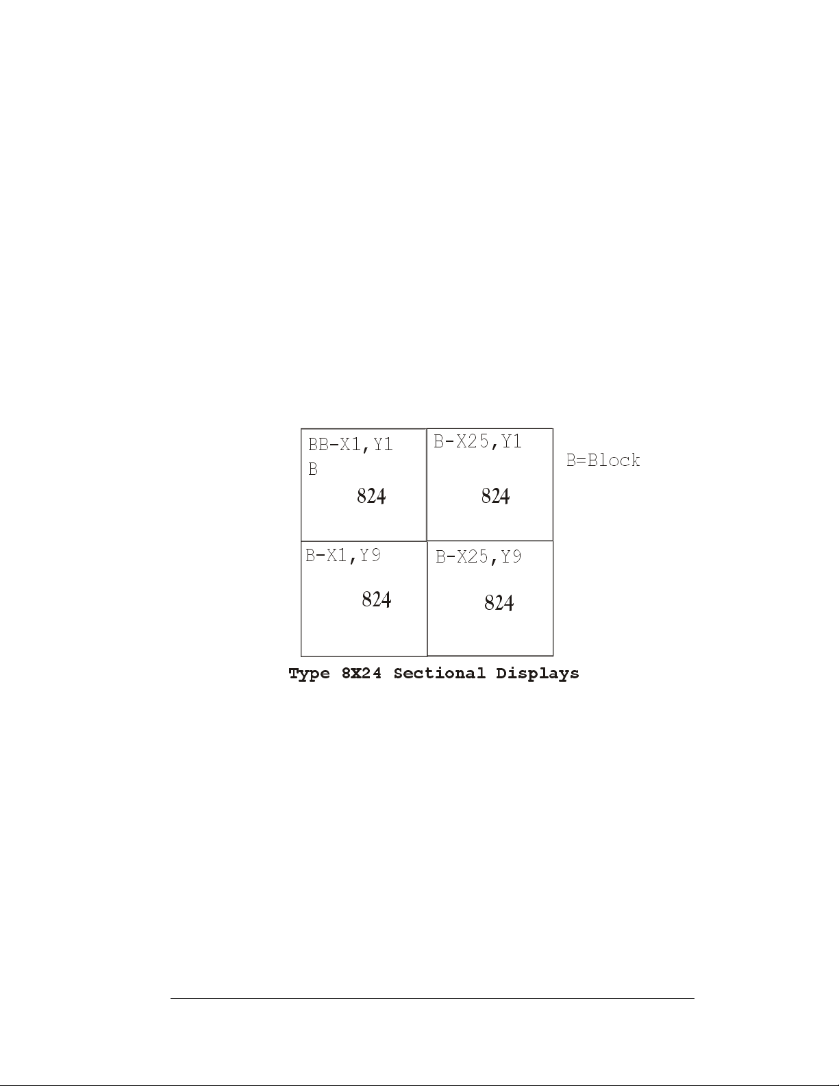
The X-coordinate refers to the LED block placement within a row of characters. To
count the placement of the X-coordinate, begin with the left-most LED block as X=1
and continue counting across through the entire display to the right-most LED block.
The Y-coordinate refers to the LED block placement within a column of characters.
To count the placement of the Y-coordinate, begin with the upper-most LED block
as Y=1 and continue counting down through the entire display to the bottom-most
LED block. The software on the control PC uses these coordinates to determine the
placement of data within the larger display.
The X,Y coordinates at the upper left character of each section need to be configured
for proper display orientation.
In addition, various Daktronics drawings may contain the following labeling
formats:
Finally, drawings commonly have Daktronics part numbers. You can use those part
numbers when requesting replacement parts from Daktronics Customer Service.
Take note of the following part number formats:
Introduction
Figure 2: Positions-1648 Display
• “TB_ _” shows a termination block for power or signal cable.
• “F_ _” denotes a fuse.
• “E_ _” signifies a grounding point.
• “J_ _” stands for a power or signal jack.
• “P_ _” represents a power or signal plug for the opposite jack.
• “0P-_ _ _ _-_ _ _ _” gives the form of an individual circuit board, such as a
module driver.
1-5
Page 10

• “0A-_ _ _ _-_ _ _ _” represents an assembly, such as a circuit board and the
plate or bracket to which it mounts. A collection of circuit boards working
as a single unit may also carry an assembly label.
• “W-_ _ _ _” indicates a wire or cable. Cables may also carry the assembly
numbering format in certain circumstances. This is especially true of ribbon
cables.
• “F-_ _ _ _” signifies a fuse.
Most circuit boards and components within this sign
carry a label that lists the part number of the unit. If
the Replacement Parts List in Section 4.13 does not
list a circuit board or assembly, use the label to order a
replacement.
Figure 3 illustrates a typical label. The
Figure 3: Typical Label
part number is in bold.
1-6
Introduction
Page 11

Section 2: Mechanical Installation
Reference Drawings:
Shop Dwg; CE-1010-***-1.2-RG-Thin Mount
Shop Dwg; CE-1010-4**-2.1-RG-Thin Mount
Shop Dwg; CE-1010-***-2.1-RG-Thin Mount
Shop Dwg; CE-1010-***-3.2-RG-Thin Mount
Shop Dwg; CE-1010-***-4.2-RG-Thin Mount
Spacing Plate; XX.XX" Tall-Thin Mount
Shop Dwg; Install Notes-Thin Mount
Mtg Brkt Assy; CE-10**-824-2.1-Thin
Shop Dwg; Install Details CE-1010-1672-2.1-Thin
Generic; System Riser Diagram
The sectional display models shown in Draw
151293 and A-154044 are available in various standard sizes and can be arranged to create
larger display sizes. The arrangement of these sections requires Daktronics contract
engineering.
Daktronics contract engineering and the Daktronics project manager will provide installation,
l
ayout, and riser diagrams once the overall display size has been determined. Drawings A-
152630, A-152599, A-155773, and B-155789 are typical illustrative drawings of those that
are contract specific, and are made available by the Daktronics project manager. Installation
drawings are also included in the installation kits that co me with the d isp lay section(s).
It is important to have received and reviewed the installation drawings and riser
dia
grams before installation begins. Installation personnel should be familiar with these
drawings and have copies of them on site.
........................................Drawing A-152599
.......................................Drawing A-155773
...............................................Drawing A-113523
ings A-154011, A-151214, A-152954, A-
Note: Daktronics engineering staff must approve any changes made to the display. If any
modifications are made, detailed drawings of the changes must be submitted to Daktronics
for evaluation and approval, or the warranty may be void.
Refer to the shop draw
manager.
ings referenced above, and the other drawings provided by the project
...........................Drawing A-154011
...........................Drawing A-151214
...........................Drawing A-152954
...........................Drawing A-151283
...........................Drawing A-154044
....................................Drawing A-152630
...................Drawing B-155789
2.1 Support Structure Design
The wall, framing members, or structure that will support the Daktronics supplied Zbrackets and display sections are to be designed to support the weight of the
completed system. Review all drawings to determine special requirements and the
total system weight. It is the customer’s responsibility to ensure that the installation
will meet local codes and or standards. Daktronics is not responsible for the
installations or the structural integrity of support structures done by others.
Mechanical Installation
2-1
Page 12

2.2 Z-Bracket Installation for Sectional Display Mounting
Review all drawings to determine special requirements. Display sections are to be
mounted to a wall or structural frame using Z-shaped aluminum brackets provided
by Daktronics in an installation kit. The Z-brackets allow for one (1) inch of air
space behind the displays for power and signal terminations, and for the
corresponding customer supplied junction boxes. Installation drawings will provide
the necessary dimensions for the mounting of the display, Z-brackets, and power
termination junction boxes.
It is the customer’s responsibility to attach the Z-brackets with the correct am
and type of hardware to support the weight of all display sections mounted to those
Z-brackets as well as the support structure mentioned in Section 2.1. It is the
customer’s responsibility to ensure that the installation will meet local codes and or
standards. Daktronics is not responsible for the installations or the structural
integrity of support structures done by others.
When mounting a display system containing one or multiple rows of display
sectio
ns, the bottom row of displays will require two rows of Z-brackets attached to
the support structure. Upper rows of displays will require only one row of Z-brackets
per row of displays. This is due to the fact that each display section has alignment
pins located on the top of the section that interlo c k into the bottom of the display
section stacked on top of it. It is important to check these pins for tightness before
hanging a display section.
ount
2.3 Electrical Junction Box Installation
Review all drawings to determine special requirements. Installation drawings will
provide the necessary dimensions for the power termination junction boxes. The
contract specific riser diagram will identify power specifications for the display
system. Also read Section 3 for any other pertinent information that may be needed
during the mechanical installation process.
2.4 Hanging Display Sections
Each DataTrac CE-1010 section has threaded insert nut holes on the rear side for the
attachment of mounting brackets. These are required for the hanging of the
individual sections. The mounting brackets come in the installation kit along with
the required ¼-20x3/4 hex head bolts. A drawing or drawings showing the correct
mounting bracket attachment will be included in the installation kit. Drawing A-
155773 illustrates the attachment of mounting brackets.
Hang the section that receives the incoming signal to the bottom
mounted Z-brackets. Subsequent sections are to be mounted to the Z-brackets, as
they are daisy-chained together with signal interconnects per the contract specific
riser diagram and Section 3 for electrical and signal information.
2-2
left side of the
Mechanical Installation
Page 13

Each section is labeled with an address and X
proper section is mounted to the Z-bracket in the proper place.
Make sure that the mounted Z-brackets have screws attached vertically to each
end to prevent the display sections from sliding off. This is discussed and
illustra
ted in the included install kit drawings.
-Y coordinate. Make sure that the
2.5 Display Ventilation Requirements
Fresh air inlets and exhaust vents should not be obstructed in any way. Using the
Daktronics suggested mounting methods will ensure proper ventilation. If using a
different mounting method, consult a Daktronics sales representative for clearance
requirements regarding the particular display. If ventilation requirements are not
met, the display warranty will be void.
Mechanical Installation
2-3
Page 14

Page 15
Section 3: Electrical Installation
3.1 Signal
Cables
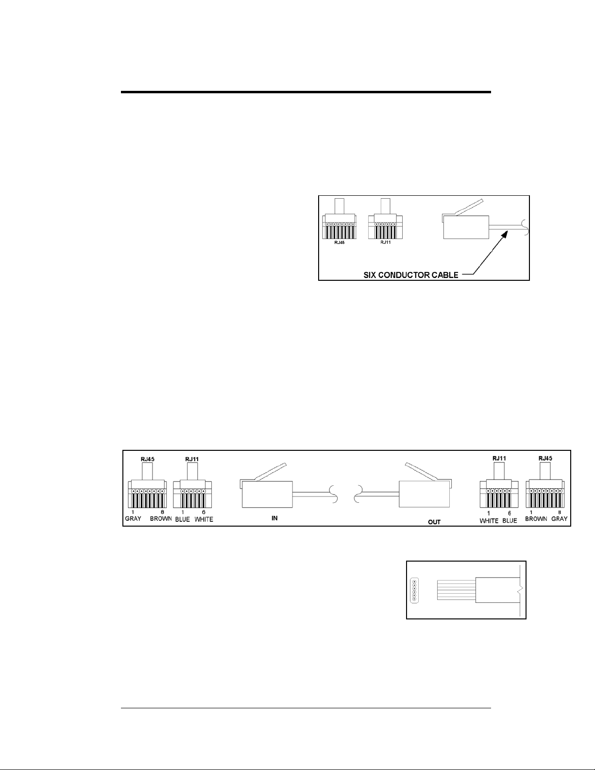
The conductor connector used in the
network is an industry standard 6-pin
RJ11 or an 8-pin RJ45. This
connector can be found on many
telephones and LANs.
The cable used in the network is a
standard flat six-conductor telephone
cable (standard flipped cable). Refer
to Figure 4. This cable has one end
that is the mirror image of the other end (i.e. the cable is flipped). Refer to Figure 5
for a standard flipped cable.
Notice in Figure 5 that the color code on one connector must be made the opposite
on the other connector. When installing a network, it is not easy to remember in
which direction the previous end was oriented. One simple way to avoid confusion
is to standardize the color code, having one color for the connector going into the
output of a sign, and the opposite color for a connector going into the input of a
sign. This will help ensure correct cabling since cables are always installed from the
output jack of one sign to the input jack of the next sign.
Figure 4: Six conductor RJ11 Connector and
Cable
Figure 5: Flipped Cable with RJ Connectors
Installing an RJ11 Connector
Installing an RJ11 connector on the end of the sixconductor cable is a simple task when the correct tools are
used. The RJ11 crimping tool (Daktronics part number TH-
1033) performs two separate steps.
First, use the crimping tool to strip the outer insulation from the inner wires. This
does not result in bare wires since only the gray outer jacket is removed. After
correct stripping, the wire will appear as shown in Figure 6.
Electrical Installation
Figure 6: Wire with Outer
Jacket Stripped
3-1
Page 16
The crimping tool is then used to crimp the RJ11 connector onto the cable. The RJ11
connector is locked into a special socket in the tool. The stripped wire is inserted
into the RJ11 connector. Finally, the tool is squeezed like a pliers to crimp the
connector onto the wire. This completes the installation of an RJ11 connector onto
the wire.
3.2 Power
Reference Drawing:
Generic; System Riser Diagram..................................Drawing A-113523
Power Requirements
Each display system comes with a contract specific riser diagram similar to the
drawing referenced above.
Refer to the specifications sheet for voltage and current requirements. The displays
accept a universal input voltage of 85-265 VAC at 50 or 60 Hz.
Do not connect the display to any voltage other than that listed on the Daktronics
product label attached to the back of the display.
Grounding
Proper grounding is necessary for reliable equipment operation, and provides some
protection to the equipment from damaging electrical disturbances. All of the
displays are supplied with a power cord that contains an earth ground conductor.
Make sure to plug this cord into a grounded outlet. If the proper grounding methods
are not followed, the warranty will be void.
Note: Displays must be earth grounded according to national and local electrical
codes.
3-2
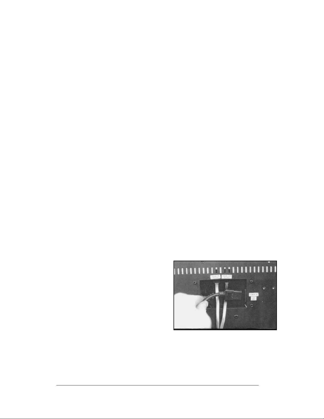
Power Connection – Pluggable Cord Connected Displays
The DataTrac CE-1010 displays are
supplied with an eight (8) foot power cord.
The socket-outlet should be installed near
the equipment and be easily accessible.
Plug the power cord into the socket as
shown in Figure 7.
It is important to check this connector to
make sure it is fully secured before
hanging a display section.
Figure 7: Power Cord Connection
Electrical Installation
Page 17
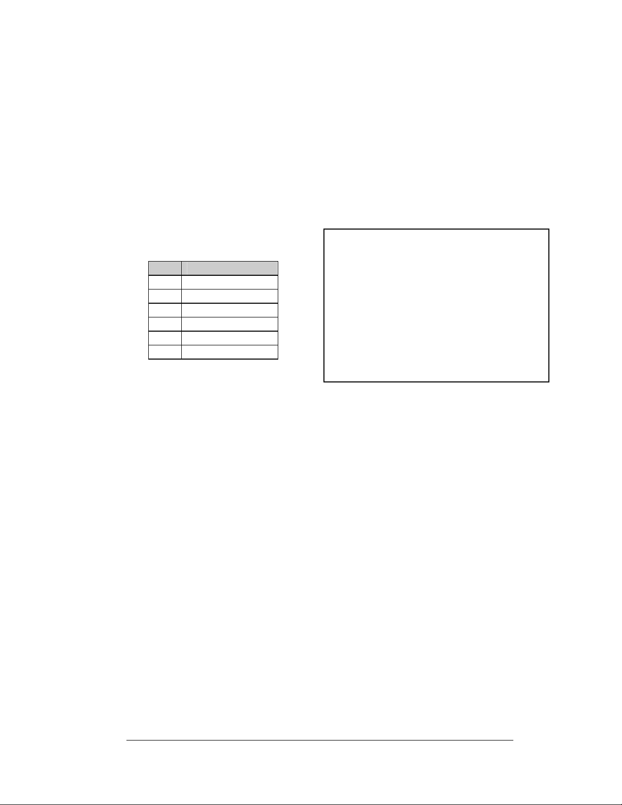
3.3 RS422 System
A RS422 system requires a signal converter to connect the first sign to the computer.
1. Plug the serial cable’s 25-pin connector into the signal converter.
2. Plug either the 9-pin or the 25-pin connector (depending on your PC) into
the RS232 COM port to be used.
3. Plug the signal converter’s power cord into a 120 VAC grounded outlet.
4. Plug a flipped phone cable into the “RS422 OUT” of the signal converter
and the opposite end into the “RS422 IN” of the first display.
The “RS422 IN” jack’s pin out is as
follows:
Pin Function
1 N.C.
2 D1OUT-P
3 D1OUT-N
4 D1IN-P
5 D1IN-N
6 N.C.
Figure 8: Output Signal Cable Connection
3.4 Sign to Sign/Section to Section Connections
When wiring the sign to sign network, the cable and connectors discussed earlier in
this section are used. Pay special attention to the information regarding flipped
cables to help ensure a successful installation. The best method of wiring the signs
together is to start at the first sign, as it is designated to begin the n etwork.
1. Plug the cable into the “SIGNAL OUT” output jack of the first sign (refer
to Figure 8) and the other end of the cable into the input jack of the next
sign.
2. Continue this procedure throughout the network. When the wiring is
complete, the last sign will have nothing in the output jack.
3. Before hanging the displays, review Section 2.4.
Electrical Installation
3-3
Page 18

Page 19

Section 4: Maintenance and
Troubleshooting
Important Notes:
1. Disconnect power before any repair or maintenance work is
done on the display.
2. Qualified service personnel must make any access to internal
display electronics.
3. Disconnect power when the display is not in use.
Reference Drawings:
Label Detail Drawing, CE-10**-****-*.*, RS422.........................Drawing A-110324
1.2" Displays
Final Assy; CE-1010-****-1.2-RG .............................................Drawing B-110268
Schematic; CE-10**-824/30-1.2-**............................................Drawing B-113015
Schematic; CE-10**-1224/30-1.2-**..........................................Drawing B-113344
2.1" Displays
Final Assy; CE-1010-4**-2.1-SBRG .........................................Drawing B-140722
Final Assy; CE-1010-****-2.1-RG .............................................Drawing B-121808
Schematic; CE-10**-424/30-2.1-**............................................Drawing B-140608
Schematic; CE-10**-824/30-2.1-**............................................Drawing B-121853
Schematic; CE-10**-1224/30-2.1-**..........................................Drawing B-121854
3.2" Displays
Final Assy; CE-1010-****-3.2-RG .............................................Drawing B-146115
Schematic; CE-10**-418/24-3.2-**............................................Drawing B-145059
Schematic; CE-10**-618/24-3.2-**............................................Drawing B-144982
4.2" Displays
Final Assy; CE-1010-****-4.2-RG .............................................Drawing B-110430
Schematic; CE-10**-412/18-4.2-**............................................Drawing B-107790
Schematic; CE-10**-612/18-4.2-**............................................Drawing B-109996
The DataTrac CE-1010 displays are front access. The components within the displays are not
field repairable. In most cases, it is easiest to completely replace the failed part or return it to
Daktronics for repair.
Refer to the project specific shop drawings provided by the project manager.
Maintenance and Troubleshooting
4-1
Page 20
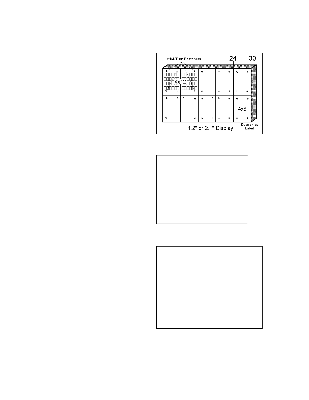
4.1 Accessing the Interior of the Display
Depending on the overall size of a
display system, sectional displays may
have two sizes of front access
removable panels. Finding the
Daktronics labels on the front of the
display will help in locating the lower
right corner of a display section.
For 1.2" and 2.1" display types, the
module in this corner may either be a
4x6 or 4x12 panel. For 3.2" and 4.2"
displays, the modules are all 2x6
panels. Panels are removed by
accessing ¼-turn fasteners in the
corners of a module panel.
Note: Not every hole has a ¼-turn
fastener. Only the four corner holes of
the module panel do. Refer to Figure
9.
The screwdriver must pass through the
face panel. The ¼-turn screws are
located behind the face panel.
Using a #1 Philips screwdriver, turn
the 4 ¼-turn screws securing the LED
module panel to the cabinet of the
display one-quarter turn counterclockwise. Refer to Figure 9 and
Figure 10. The screws are designed to
remain in the LED module flanges,
but release from the cabinet.
Gently pull the LED module panel
from the body of the display. It will
come forward as a complete unit.
Refer to Figure 9 and Figure 10.
Note: Use caution when removing the
LED module panel. The power wires
and ribbon cable connecting the LEDs
to the inside of the display will still be
connected. Take care not to scratch the
modules wire cloth filter.
Figure 9: Screw Locations
Figure 10: Locating module panel ¼-turn fasteners
Figure 11: Module Panel Removal
4-2
Maintenance and Troubleshooting
Page 21
To completely remove the LED module panel from the cabinet of the display:
1. Spread the clasps of the 40-
pin connectors on the rear
side of the panel.
2. Gently pull the cable to
disconnect the pin connector
(refer to Figure 12).
3. Disconnect the four-pin
power connectors. The power
cable is released by squeezing
the tabs on each side of the
connector.
Figure 12: LED Module Ribbon Cable Removal
4.2 Display Interior
Once the LED module panel is removed, the display interior is visible. Various
internal components, including the display controller and the power supplies, are
now accessible for repair or replacement.
LED Module Replacement
If any LED modules fail, the recommended
procedure is to replace the failed module,
send it to Daktronics, or send it to a certified
dealer for repair. Refer to Section 4.6 for
information on packaging components for
shipment.
To remove an LED module:
1. Remove the appropriate LED
module panel as described in
Section 4.1.
2. Disconnect the remaining 40-
pin ribbon cable from the failed
module.
3. Removing the wire cloth retainer frame requires the following: For 1.2"
displays, remove the four nuts located along the rear edge of the LED
circuit board. For the 2.1" displays, remove the four perimeter nuts and
one in the center of the circuit board. For the 3.2" and 4.2" displays,
remove the six perimeter nuts and two in the center. Refer to Figure
13.
4. Flip the module panel over and remove the wire cloth filter from the
front of the failed module.
Figure 13: Removing the wire cloth
retainer frame nuts
Maintenance and Troubleshooting
4-3
Page 22

5. Remove the screws located along
the top and bottom edge of the
module, and lift the PC board off of
the rails. Refer to Figure 14.
6. Reverse the previous procedure to
attach a new module.
Figure 14: Removing Top and Bottom Module
Screws
Power Supply Replacement
1.2" and 2.1" Power to the LED modules is
provided by small 5V power supplies. Each
power supply can support two 4x6 modules.
The controller board also requires a 5V power
supply. The power supplies are mounted to the
back sheet within the display cabinet.
3.2" and 4.2" Power to the LED modules is
provided by 6.5V power supplies. Each power
supply can support two 2x6 modules. The
controller board also requires a 5V power
supply.
Figure 15: Power Supply
To remove a power supply that has failed, first
remove the LED module in front of the failed
power supply as described in Section 4.1.
Each power supply is attached to a power
supply plate by two metric screws. The plate is
secured to the back sheet by two (2) #6 hex
head screws. Refer to Figure 15. Use a
3
/16-nut
driver to remove the #6 hex head screws.
Lift the power supply and plate back. The
metric screws securing the power supply to the
Figure 16: Power Supply Cable Connections
plate are now accessible. Use a #1 Philips head screwdriver to remove the screws and
free the power supply.
Disconnect the power cables as shown in Figure 16. The power supply is now fully
released and ready for replacement. Follow the previous steps in reverse order to reattach
the new power supply. Refer to the display’s schematic for the proper wiring
configuration.
4-4
Maintenance and Troubleshooting
Page 23

Display Controller
The display controller is mounted to the inside rear of the display cabinet. Refer to
Figure 17 for an illustration of the controller and the appropriate schematic for its
location in the display. The controller receives information from the computer, interprets
it, and activates the appropriate LEDs on the display. The display controller also has a set
of eight switches by which an address can be set using standard binary code (refer to
Section 4.3).
Figure 17: MDC Controller
Under normal operation, the normal state of the controller’s status indicator LEDs is as
follows:
Status Indicator Normal State
MDC Power LED On Constant
Product Board Power
LED
Run LED Flashes once per
To replace a failed controller:
1. Remove the module panels as described in Section 4.1. Each display section has
one controller mounted inside it. Refer to the appropriate schematic for the
controller location.
2. Disconnect the power cable and signal ribbon cables. Release the power cable
by squeezing the tabs on each side of the connector. Release the signal ribbon
cables by spreading the clasps on the jack and gently pulling up on the ribbon
cable. Take note of the signal cables and their appropriate jacks.
3. Remove all #6 connecting screws and the controller will be free. If the address
switches are used, take note of the switch configuration and set the same address
on the new controller.
4. To install a new controller, reverse the previous procedure.
On Constant
second
Maintenance and Troubleshooting
4-5
Page 24

4.3 Controller Address and Test Mode
The controller has a set of “DIP” switches on
the side of the controller as shown in Figure
18. These DIP switches set the hardware
address. When replacing a controller board,
be sure to set the DIP switches in the same
address configuration as the defective
controller. Turn power off and then back on to
recognize the new address.
Note: Setting the DIP switches to address 0
(turn all the switches to OFF by flipping them
toward the printed switch numbers) can
activate a test mode. The display’s power
must be downed and then reconnected to run
the test mode.
Switch 8 Switch 7 Switch 6 Switch 5 Switch 4 Switch 3 Switch 2 Switch 1 Address
Off Off Off Off Off Off Off On 1
Off Off Off Off Off Off On Off 2
Off Off Off Off Off Off On On 3
Off Off Off Off Off On Off Off 4
Off Off Off Off Off On Off On 5
Off Off Off Off Off On On Off 6
Off Off Off Off Off On On On 7
Off Off Off Off On Off Off Off 8
Off Off Off Off On Off Off On 9
Off Off Off Off On Off On Off 10
Off Off Off Off On Off On On 11
. . . . . . . . . . . . . . . . . . . . . . . . . . .
On On On On Off Off Off Off 240
Figure 18: End View; Display
Controller DIP Switches
4.4 Troubleshooting
This section contains some symptoms that may be encountered with the LED
displays. Possible remedies are provided. This list does not include every possible
problem, but does represent some of the more common situations that may occur.
Symptoms/Conditions Possible Cause/Remedy
Cannot communicate with the
display.
Display will not run. • Check power cord.
4-6
• Check flipped phone cable connections.
• Check display configuration.
• Check signal converter TX and RX LEDs.
• Power down, then power up the display.
• Check the controller status indicators.
Maintenance and Troubleshooting
Page 25

Entire display is garbled or a
• Power down, then power up the display.
section of the display is bad.
Section of the display network is
not working.
• Bad input on the first bad display.
• Bad output on the last good display.
• Switch the suspect display with a known good display.
Note: The display configuration is shown on operation and contains the following
inform
ation:
1. Posi
2. Firm
3. Si
4. C
5. C
6. Di
7. M
tions (x=1, y=1)
ware Version
ze 4x8
OM1 Configuration (DataView
OM2 Configuration (DataView
™
19200)
™
9600)
splay Address—displayed in binary code (i.e. 001)
odem (if present)
4.5 Replacement Parts
Common Parts
Part Description Part Number
DataTrac CE-1010 Display Manual ED11477
Signal Converter- 120 VAC 0A-1127-0255
Signal Converter- 240 VAC 0A-1127-0250
Serial Cable W-1249
Adapter DB9M to DB25F A-1603
Patch Cable, 10ft, RJ45, 4 Pair Twisted W-1383
Network Tester 0A-1146-0005
Display Interconnect Cable 0A-1120-0176
Power Cord, 120VAC W-1181
Cable, 18” RJ11 6-cond straight 0A-1137-0160
Cable; 25” RJ11 6-cond straight W-1265
Cable, 36” RJ11 6-cond straight 0A-1120-0134
Cable, 100” RJ11 6-cond straight 0A-1146-0002
Cable; 500” RJ11 6-cond straight 0A-1146-0003
Cable Assy; 40 Pos 8” W-1341
Cable Assy; 40 Pos 18” W-1362
Cable Assy; 40 Pos 36” 0A-1000-0006
Power Supply; 5V @10A A-1568
Power Supply; 6.5V @15A A-1591
1.2” Display
Controller- 422 DVIEW 0A-1120-0135
Controller- 422 V1500 0A-1120-0016
Module; CE-10**-4x6-1.2-RG 0P-1120-0030
Panel; CE-1010-4x6-1.2-RG-Flush 0A-1120-0514
Panel; CE-1010-4x6-1.2-RG-Flush 0A-1120-0515
2.1” Display
Controller- 422 DVIEW 0A-1120-0135
Maintenance and Troubleshooting
4-7
Page 26

Controller- 422 V1500 0A-1120-0016
Module; CE-10**-4x6-2.1-SBRG 0P-1120-0034
Panel; CE-1010-4x6-2.1-RG 0A-1120-0132
Panel; CE-1010-4x12-2.1-RG 0A-1120-0131
Panel; CE-1010-4x6-231-RG 0A-1120-0448
Panel; CE-1010-4x12-2.1-RG 0A-1120-0496
3.2” Display
Controller- 422 DVIEW 0A-1120-0136
Controller- 422 V1500 0A-1120-0530
Module; CE-10**-26-3.2-RG 0P-1120-0035
Panel; CE-1010-2x6-3.2-RG-Flush 0A-1120-0533
4.1” Display
Controller- 422 DVIEW 0A-1120-0136
Controller- 422 V1500 0A-1120-0530
Module; CE-10**-2x6-4.2-RG 0P-1120-0031
Panel; CE-1010-2x6-4.2-RG 0A-1120-0529
Previously Used Parts
Part Description Part Number Dates Used In Displays
Panel: CE-1010-4x6-1.2-RG 0A-1120-0152 Before 10/31/00
Panel : CE-1010-4x12-1.2-RG 0A-1120-0153 Before 10/31/00
Module; CE-10**-4x6-2.1-RG 0A-1120-0130 7/16/98-9/15/99
Module; CE-10**-4x6-2.1-SBRG 0P-1120-0032 9/15/99-10/31/00
Panel; CE-1010-4x6-2.1-RG 0A-1120-0132 7/16/98-9/15/99
Panel; CE-1010-4x12-2.1-RG 0A-1120-0131 7/16/97-9/15/99
Panel; CE-1010-4x6-2.1-RG 0A-1120-0448 9/15/99-10/31/00
Panel; CE-1010-4x12-2.1-RG 0A-1120-0449 9/15/99-10/31/00
Panel; CE-1010-2x6-4.2-RG 0A-1120-0137 11/19/98-3/8/01
4.6 Daktronics Exchange and Repair and Return
Programs
To serve customers' repair and maintenance needs, Daktronics offers both an
Exchange Program and a Repair and Return Program.
Daktronics' unique Exchange Program is a quick, economical service for replacing
key
components in need of repair. If a component fails, Daktronics sends the
customer a replacement, and the customer, in turn, sends the failed component to
Daktronics. This not only saves money but also decreases scoreboard downtime.
Daktronics provides these plans to ensure users get the most from their Daktronics
product
guidelines explained below. Please call the Help Desk 877-605-1115 if you have
questions regarding the Exchange Program or any other Daktronics service.
4-8
s, and it offers the service to qualified customers who follow the program
Maintenance and Troubleshooting
Page 27

When you call the Help Desk, a trained service technician will work with you to
solve the equipm
determine which replacement part to ship. If, after you make the exchange, the
equipment still causes problems, please contact our Help Desk immediately.
If the replacement part fixes the problem, package the defective part in the same box
and wrapping in which the replacem
UPS shipping document, and return the part to Daktronics. In most
circumstances, you will be invoiced for the replacement part at the time it is shipped.
This bill, which represents the exchange price, is due when you receive it.
Daktronics expects immediate return of an exchange part if it does not solve the
problem
damaged due to acts of nature or causes other than normal wear and tear.
If you do not ship the defective equipment Daktronics within 30 working days from
the invoice date, Daktronics assum
outright (with no exchange), and you will be invoiced for it. This second invoice
represents the difference between the exchange price and the full purchase price of
the equipment. The balance is due when you receive the second invoice.
If you return the exchange equipment after 30 working days from the invoice date,
you will be credited for the am
To avoid a restocking charge, you must return the defective equipment within
30 days from the invoice date.
Daktronics also offers a Repair and Return Program for items not subject to
exchange.
Return Materials Authorization: To return parts for serv
representative prior to shipment to acquire a Return Material Authorization (RMA)
number. If you have no local representative, call the Daktronics Help Desk for the
RMA. This expedites repair of your component when it arrives at Daktronics.
Packaging for Return: Pack
damaged in shipment. Electronic components such as printed circuit boards should
be installed in an enclosure or placed in an antistatic bag before boxing. Please
enclose your name, address, phone number and a clear description of symptoms.
This is how to reach us:
Ma
PO Box 5128
Phone:
Fax: 605-697-4444
E-ma
. The company also reserves the right to refuse equipment that has been
il: Customer Service, Daktronics Inc.
331 32nd Ave
Brookings SD 57006
Daktronics Help Desk: 877-605-1115 (toll free)
or 605-697-4036
il: helpdesk@daktronics.com
ent problem. You will work together to diagnose the problem and
ent part arrived, fill out and attach the enclosed
es you are purchasing the replacement part
ount on the second invoice, minus a restocking fee.
ice, contact your local
age and pad the item well so that it will not be
Maintenance and Troubleshooting
4-9
Page 28

Page 29

Appendix A: Reference Drawings
General Drawings:
Generic; System Riser Diagram
Label Detail Drawing, CE-10**-****-*.*, RS422
Spacing Plate; XX.XX" Tall-Thin Mount
Shop Dwg; Install Notes-Thin Mount
Mtg Brkt Assy; CE-10**-824-2.1-Thin
Shop Dwg; Install Details CE-1010-1672-2.1-Thin
1.2" Displays
Shop Dwg; CE-1010-***-1.2-RG
Final Assy; CE-1010-****-1.2-RG
Schematic; CE-10**-824/30-1.2-**
Schematic; CE-10**-1224/30-1.2-**
2.1" Displays
Shop Dwg; CE-1010-4**-2.1-RG
Shop Dwg; CE-1010-***-2.1-RG
Final Assy; CE-1010-4**-2.1-SBRG
Final Assy; CE-1010-****-2.1-RG
Schematic; CE-10**-424/30-2.1-**
Schematic; CE-10**-824/30-2.1-**
Schematic; CE-10**-1224/30-2.1-**
3.2" Displays
Shop Dwg; CE-1010-***-3.2-RG
Final Assy; CE-1010-****-3.2-RG
Schematic; CE-10**-418/24-3.2-**
Schematic; CE-10**-618/24-3.2-**
4.2" Displays
Shop Dwg; CE-1010-***-4.2-RG
Final Assy; CE-1010-****-4.2-RG
Schematic; CE-10**-412/18-4.2-**
Schematic; CE-10**-612/18-4.2-**
......................................................Drawing A-113523
...............................Drawing A-110324
..........................................Drawing A-152630
...............................................Drawing A-152599
..............................................Drawing A-155773
.........................Drawing B-155789
.....................................................Drawing A-154011
....................................................Drawing B-110268
..................................................Drawing B-113015
................................................Drawing B-113344
.....................................................Drawing A-151214
.....................................................Drawing A-152954
................................................Drawing B-140722
....................................................Drawing B-121808
..................................................Drawing B-140608
..................................................Drawing B-121853
................................................Drawing B-121854
.....................................................Drawing A-151283
....................................................Drawing B-146115
..................................................Drawing B-145059
..................................................Drawing B-144982
.....................................................Drawing A-154044
....................................................Drawing B-110430
..................................................Drawing B-107790
..................................................Drawing B-109996
Appendix A: Reference Drawings
A-1
Page 30

Page 31

Page 32

Page 33

Page 34

Page 35

Page 36

Page 37

Page 38

Page 39

Page 40

Page 41

Page 42

Page 43

Page 44

Page 45

Page 46

Page 47

Page 48

Page 49

Page 50

Page 51

Page 52

Page 53

Page 54

Page 55

Page 56

Page 57

Page 58

Page 59

Page 60

Appendix B: Signal Converter
Appendix B: Signal Converter
B-1
Page 61

Page 62

Signal Converters and Loop-back Testing
for Direct Connections
The following table gives the typical state of the signal converter when the LEDs are either on
or off. Refer to
converters and the locations of the various components.
LED
Indicators
Power
TX
RX
TX/RX
Figure 1 and Figure 2 on next the page for an illustration of the signal
Typical States Troubleshooting
ON
OFF
On Steady
OFF Steady
Brief Flicker SC is transmitting data
ON Steady
OFF Steady Normal state, SC is not receiving data
Brief Flicker SC is receiving data
ON Steady (If serial cable is connected) Bad SC Replace SC
Signal Converter (SC) is receiving
power
SC is not receiving power Check power/Replace fuse
Internal 1 AMP fuse is bad Replace fuse
SC is not connected to a serial port Connect to open computer
1. Serial port or serial cable is bad
2. Computer COM port is in sleep
mode
Normal state, SC is not transmitting
data
1. Field cabling between SC and display
is bad
2. Is connected to display output jack or
terminated inc
3. Bad COM port is on display controller
orrectly
COM port (COM port could be
sleep mode.)
1. Try another port or replace
seri
2. Communicate with display
1. Eliminate cabling by
discon
from SC to display controller
2. Check connections and
terminatio
3. Eliminate by disconnecting
wire/
controller
al cable
necting wire/cable
ns
cable to display
6/30/2004
ED-14413
Page 1
Page 63

RS422 Wire Signal Converter
following tables list the jack pin-outs for a wire signal converter:
The
Figure 1: RS232/RS422 Signal Converter
Fiber Signal Converter
The following tables give the jack pinouts for a fiber signal converter.
JACK OPERATION
J2 TX1 (out)
J3 RX1 (in)
J4 TX2 (out)
J5 RX2 (in)
J1 - 25 Pin DB-F
PIN OPERATION
2 TX-P (out)
3 RX-P (in)
7 GND
J4 and J5 –
Phoenix
PIN OPERATION
1 GND
2 RX-P (in)
3 RX-N (in)
4 TX-P (out)
5 TX-N (out)
6 GND
J2 and J3 –
RJ/11
PIN OPERATION
1 GND
2 TX-N (out)
3 TX-P (out)
4 RX-N (in)
5 RX-P (in)
6 GND
J1 – 25 Pin DB-F
PIN OPERATION
2 TX-P (out)
3 RX-P (in)
7 GND
Figure 2: RS232/Fiber Signal Converter
6/30/2004
ED-14413
Page 2
Page 64

RS422 Loop-Back Test (Outdoor Displays)
Note: This test should be performed with only one jack at a time. Do not connect a loop-back
to more than one jack at a time.
Serial Cable (W-1249)
To complete the test, the serial cable must be plugged into the signal converter. The table
below lists the pin connections when using a serial cable (Daktronics part# -1249).
DB9-F DB25-F
Pin 3 – TX Pin 2 – TX
Pin 2 – RX Pin 3 – RX
Pin 5 – GND Pin 7 - GND
Loop-Back Test: To perform a loop-back for
testing purposes only, use the spare plug in the
signal converter and connect the copper conductor
jumpers using the following table. Refer to
Figure 3. (To eliminate the display, pull out the
phoenix plug with the signal wires connected into
it.)
J2 and J3 J4 and J5
(Pin 5) TX-N to
(Pin 3) RX-N
(Pin 4) TX-P to
(Pin 2) RX-P
When the wires are connected, perform the loop-back test using the
Venus 1500 software as described in Conducting the Venus 1500
Software Test
This test can also be done at the signal termination enclosure on the
surge board assembly, as shown in
controller board input. In that case, the wires coming from the signal
converter must remain connected, and the jumpers will be inserted
along with them. Leave the plug disconnected from the surge board
while conducting the test.
TB1 - RS422 In
(Pin 4) RX-P to
(Pin 2) TX-P
(Pin 5) RX-N to
(Pin 3) TX-N
When the wires are connected, perform the loop-back test using the
Venus 1500 software as described in Conducting the Venus 1500
Software Test
(Pin 2) RX-P to
OR
(Pin 3) RX-N to
(Pin 4) TX-P
(Pin 5) TX-N
Figure 4, or, on some displays, at the
Figure 3: Jumpers at RS232/RS422 Signal Converter
Figure 4: Jumpers at Surge
Board
6/30/2004
ED-14413
Page 3
Page 65

RS422 Loop-Back Test (Indoor/Outdoor Displays)
All indoor displays and some outdoor displays (AE-3010, AF-3010, AF-3020, and X-1000)
use RJ11 plugs or connectors. In those cases, a “Network Cable Tester” (
to conduct the test.
The Network cable tester is used to test for two things:
1. A flipped RJ11 cable used instead of a straight through cable.
2. A good connection from a computer or signal converter to a through the connecting
cable.
The use of a flipped (reversed) or straight cable can be determined visually. Use the figures
below as a guide, or use the Network Cable Tester box for assistance.
Figure 7) is provided
Figure 5: Flipped Cable (Reversed)
Figure 6: Straight Cable
1. Plug one end of the flipped cable into the output from the computer or signal
converter.
2. Plug one end of the flipped
cable into J2 (Loopback
Connector) on the Network
cable tester box.
3. When both ends are connected,
perform the loop-back test
using the Venus 1500 software
as described in Conducting
the Venus 1500 Software
Test.
Figure 7: Network Cable Tester
6/30/2004
ED-14413
Page 4
Page 66

4. For AE-3010, AF-3010, AF-3020, and X-1000 displays
only, disconnect the cable going into the COM module
input (J3) on the controller and connect to J2 on the
loop-back box. See
connector.
Figure 8 for location of the RJ11
Loop-Back test with Fiber
1. Locate the signal termination enclosure or open the bottom left
corner of the display
2. Locate the fiberboard, as shown in Figure 9, and label the fiber
ends connected to the board.
3. Remove the ends from the board that are in jacks J5 and J4.
4. Connect the ends into the fiber splice (Daktronics part# P-1197),
as shown in
Figure 10.
Figure 8: AF-3010/X-1000 COM
Module
Figure 10: Connecting TX and RX Fibers with Fiber Splice
5. When the fibers are connected, perform the loop-back test using
the Venus 1500 software as described in Conducting the Venus
1500 Software Test
6. For AF-3010 and X-1000 displays only, the cable that connects
the fiberboard to the controller board input uses a RJ11 jack at
the controller and can be connected to a loop-back box at J2 to
run the test as usual.
Figure 9: Fiber Optic Board
6/30/2004
ED-14413
Page 5
Page 67

Conducting the Venus 1500 Software Test
1. Open Venus 1500 Administrator.
2. Click Network Configuration and open the direct network by clicking on the [+] in
front of Direct Network.
3. Right click the network you want to test.
6/30/2004
ED-14413
Page 6
Page 68

4. Click [TEST].
5. If the Transmit LED on the signal converter flickers, the signal is getting to the
signal converter. That means that the right Com port is being used. However, if it
does not flicker, the computer has either a software or hardware problem.
6. If you get the same message in the “Received” box as in the “Sent” box, the loop-
back test was successful, implying that the cable has continuity to the point of the
connection.
Note: Flipped and straight cables will provide the same results. Check for correct
order of the wires.
7. If “No Response” appears in the “Received” box, the test failed due to one of the
following problems:
a. The correct computer COM port is not being used, or USB port is not
configured as a “serial” port. (If the Transmit LED flickered, this was not
the problem.)
b. A communication problem exists:
• The fiber or the ends on the fiber are bad.
• (or) The wire or the terminations are bad.
c. There was a problem conducting the test:
• The serial cable to the signal converter is bad or not plugged in.
• The signal converter is not plugged in.
8. If the words “It appears as if this port has a modem attached” appear, the modem will
need to be moved, or you need to use a different COM port.
After the test is complete:
1. Remove the wire jumpers and make sure terminations are correct.
2. (or) Remove the fiber splice, and reconnect fiber to fiberboard.
3. Run the test again without the jumpers, splice, or loop-back box. The test should
fail.
4. Use Venus 1500 Display Manager to receive the status to ensure communication
now works correctly.
6/30/2004
ED-14413
Page 7
 Loading...