

Page 1

Daktronics C-44 Drag Race
-
Timer & Accessories
Installation, Operation
Maintenance Manual
7175 Rev 11 -25 March 2004
ED
331 32nd Ave PO Box 5128 Brookings SD 57006
Tel 605-697-4036 or 877-605-1115 Fax 605-697-4444
www.daktronics.com e-mail: helpdesk@daktronics.com
Page 2

Page 3

ED-7175
P1067
Rev 11 — 25 March 2004
Please fill in the information below for your display; use it for reference
when calling Daktronics for assistance.
Display Serial No. ______________________________________
Display Model No._______________________________________
Date Installed __________________________________________
DAKTRONICS, INC.
Copyright © 2003
All rights reserved. While every precaution has been taken in the preparation of this manual, the
publisher assumes no responsibility for errors or omissions. No part of this book covered by the
copyrights hereon may be reproduced or copied in any form or by any means – graphic, electronic, or
mechanical, including photocopying, taping, or information storage and retrieval systems – without
written permission of the publisher.
CARS™ and C-44™ are trademarks of Daktronics, Inc.
Page 4

Page 5

Table of Contents
Table of Contents....................................................................................................................i
List of Figures .........................................................................................................................i
Section 1: Introduction..................................................................................................1-1
1.1 How to Use this Manual.............................................................................................1-1
1.2 C-44 Version Descriptions.........................................................................................1-2
C-44 Version 2.0 Enhancements..............................................................................................1-2
C-44 Version 2.1......................................................................................................................1-3
C-44 Version 2.2......................................................................................................................1-3
C-44 Version 2.3......................................................................................................................1-3
C-44 Version 2.4......................................................................................................................1-3
C-44 Version 2.5......................................................................................................................1-3
C-44 Version 2.6......................................................................................................................1-3
C-44 Version 2.7......................................................................................................................1-3
C-44 Version 2.8......................................................................................................................1-4
C-44 Version 2.9......................................................................................................................1-4
C-44 Version 3.0......................................................................................................................1-4
C-44 Version 3.1......................................................................................................................1-4
1.3 C-44 Computer Update ..............................................................................................1-5
Section 2: New Track Installation.................................................................................2-1
2.1 Unpacking/Damage Information................................................................................2-1
2.2 Daktronics Exchange/Repair & Return Programs......................................................2-1
2.3 Warranty.....................................................................................................................2-2
2.4 Parts Identification .....................................................................................................2-2
2.5 System Diagrams........................................................................................................2-2
2.6 Location Requirements...............................................................................................2-3
Signal Conduit and Cable.........................................................................................................2-3
Power .......................................................................................................................................2-3
Electrical..................................................................................................................................2-4
2.7 Mounting and Locating Equipment............................................................................2-4
Intermediate and Speed Trap Distances...................................................................................2-5
Photocells.................................................................................................................................2-5
Tree Mounting Considerations .................................................................................................2-5
Time Slip and Logging Printer Considerations........................................................................2-5
Starters’ Box Interface Mounting.............................................................................................2- 5
Isolation Interface Mounting....................................................................................................2-6
2.8 Field Wiring ...............................................................................................................2-6
Start Line/Isolation Interface Wiring .......................................................................................2-6
Start Line Photocells................................................................................................................2-8
Installation of the Three-Amber Tree.......................................................................................2-8
Intermediate Wiring (Optional) and Finish Line......................................................................2-8
Time Slip Printer/Printer Interface Wiring.............................................................................2-10
Optional: Wiring Between the Isolation Interface and Scoreboards ...................................... 2-10
2.9 Operational Check....................................................................................................2-11
Timer - Monitor - Keyboard - Isolation Interface ..................................................................2-11
Timer - Start Line - Emergency..............................................................................................2-12
Start Line Photocell Check.....................................................................................................2-13
Timer - Intermediate Photocell Check ...................................................................................2-13
Timer - Win Lights - Finish Line Photocell Check................................................................2-13
Page 6

Printers...................................................................................................................................2-13
Scoreboards (Optional) ..........................................................................................................2-13
Final Testing ..........................................................................................................................2-13
2.10 Sighting Infrared Photocells .................................................................................... 2-13
Section 3: C-44 Race Timer Operation ........................................................................3-1
3.1 General Operation...................................................................................................... 3-1
3.2 C-44 Race Controller Functions ................................................................................ 3-1
Power Button............................................................................................................................3-1
Entering Dial-ins......................................................................................................................3-1
Timers Reset ............................................................................................................................3-2
Tree Countdown Modes...........................................................................................................3-2
Sure Start..................................................................................................................................3-2
True Win/Breakout ..................................................................................................................3-2
Emergency ...............................................................................................................................3-3
Altitude Adjustment.................................................................................................................3-4
Reaction Timer.........................................................................................................................3-8
Printers.....................................................................................................................................3-8
Reset Win Light.......................................................................................................................3-8
Photocell Check .......................................................................................................................3-8
Margin of Victory (MOV)........................................................................................................3-8
3.3 Additional Functions.................................................................................................. 3-8
Help Screen..............................................................................................................................3-8
Setup Parameters Menu............................................................................................................3-9
System Configuration Settings...............................................................................................3-13
Category Settings.............................................................................................................. .....3-16
Race Operation.......................................................................................................................3-18
Infractions ..............................................................................................................................3-19
Guard Beam Option Use........................................................................................................3-19
Results System Option: Daktronics Automated Results System (CARS).............................. 3-19
Section 4: Maintenance & Troubleshooting................................................................4-1
4.1 Troubleshooting the System ...................................................................................... 4-1
Tree Problems..........................................................................................................................4-2
Printer Problems.......................................................................................................................4-2
Display Problems.....................................................................................................................4-2
Photocell Problems...................................................................................................................4-3
Monitor Problems.....................................................................................................................4-3
Isolation Interface Problems.....................................................................................................4-3
4.2 Maintenance............................................................................................................... 4-3
4.3 Replacement Parts...................................................................................................... 4-4
Appendix A: Infrared Photocells ......................................................................................... 1
A-1 Introduction to Infrared Photocells................................................................................1
A.2 Installation and Alignment; Opposed Beam Infrared Photocells...................................2
A.3 Installation and Alignment Retro-reflective Photocells.................................................3
A.4 Installation and Alignment: SM30 Series Barrel Sensors.............................................4
Appendix B: Glossary of Drag Racing Terms.....................................................................1
Appendix C: Miscellaneous Drawings................................................................................1
Page 7

List of Figures
Figure 1: ..............................................................................C-44 Main Screen 3-1
Figure 2: .................................................Altitude Adjustment Example Screen 3-5
Figure 3: ................................Time Slip Printout Showing Adjustment Factors 3-6
Figure 4: .........................................Log Printout Showing Adjustment Factors 3-6
Figure 5: ...............................................................Without Altitude Adjustment 3-7
Figure 6: .............................................................................. C-44 Help Screen 3-9
Figure 7: ..................................................................Setup Parameters Screen 3-9
Figure 8: ............................................................................Altitude Adjustment 3-10
Figure 9: .....................................................................................Combinations 3-10
Figure 10:..........................................................................Finish Line Distance 3-11
Figure 11:........................................................................Time Slip Information 3-11
Figure 12:.................................................................................Change Format 3-11
Figure 13:.....................................................................................Configuration 3-12
Figure 14:.................................................................................. Time and Date 3-12
Figure 15:.............................................................................................Timeout 3-12
Figure 16:....................................................................................... Diagnostics 3-13
Figure 17:....................................................................... Win Light Diagnostics 3-13
Figure 18:........................................................... System Configuration Screen 3-13
Figure 19:..................................................................................... Speed Traps 3-14
Figure 20:........................................................................................ Log Printer 3-14
Figure 21:............................................................................... Time Slip Printer 3-14
Figure 22:................................................................................... Speed Format 3-14
Figure 23:.............................................................................. Scoreboard Type 3-14
Figure 24:...............................................................................Dual Deep Stage 3-15
Figure 25:...................................................................................... Timer Reset 3-15
Figure 26:.............................................................................No Tree Handicap 3-15
Figure 27:......................................................................Reaction Time Display 3-16
Figure 28:..............................................................................Auto Start of Tree 3-16
Figure 29:...........................................................................Tie Break Selection 3-17
Figure 30:...................................................................Category Setting Screen 3-17
Figure 31:............................................................................Category Selection 3-19
Figure 32:................................................................Category Settings Printout 3-19
Page 8

Page 9
Section 1: Introduction
1.1 How to Use this Manual
The Daktronics C-44™ timer system utilizes the latest in microprocessor technology and is
designed and manufactured for reliability, easy service and long use.
This manual is designed to explain installation and operation of the Daktronics C-44 Drag
Race Timer. Details for display maintenance are also given. Follow all instructions as given
in the text. All instructions are given in a logical order for best installation and operation. For
questions regarding the safety, installation, operation or service of this system, please refer to
the telephone numbers listed on the cover page of this manual.
Important Safeguards:
1. Read and understand installation instructions before installing.
2. Do not drop the control console or allow it to get wet.
3. Opening or disassembly of equipment by non-qualified personnel can void the
warranty.
4. Do not disassemble the control console or the electronic controls of the display
unless you are qualified to do so and there is need for equipment to be installed or
serviced or the warranty will be void.
5. Disconnect power from the unit when not in use, or when servicing.
6. Disconnect cables from the back of the C-44 race controller at the end of the day or
when lightning is occurring in the area.
7. If field cabling is to remain connected to the isolation interface when not in use. The
isolation interface should be powered down via the front panel switch and must
remain plugged in to a three-conductor earth grounded outlet (to provide a discharge
path to ground for any voltage surges picked up by field cabling).
The box below is an illustration of Daktronics drawing numbering system. The drawing
number “7087-P08A-69945” is how Daktronics identifies individual drawings. This number
is located in the bottom right corner of the drawing. The manual will refer to drawings by the
last five digits and the letter preceding them. In the example, the drawing would be referred to
as Drawing A-69945. All drawings referred to as such will be inserted at the end of each
section unless otherwise specified.
Introduction 1-1
Page 10

1.2 C-44 Version Descriptions
C-44 Version 2.0 Enhancements
Split Tree Operation
Split tree operation allows each side to count down in its own mode. The split tree is
enabled by setting up a category with split tree set on and selecting two different tree
modes. Next, select the category. Both lanes will default to the 1st tree setting, but either
lane can be switched to a different mode. Press <ALT><F5> to select the mode for the
left lane and <SHIFT><F5> to select the mode for the right lane. The right lane tree
mode will be displayed below the right lane on the C-44 monitor.
When not in a split tree mode, only one line will show below the left lane on the monitor
and that will be the mode for both lanes. When in a split tree mode and if the handicap is
on or if True Win is on, the timer will account for the different tree times when counting
down. For example, if the dial-in times were the same or zero and there was a full tree on
the left lane and a pro tree on the right lane, the left tree will start 1st and then the right
tree would start after it so that both would go green at the same time. If handicap and
True Win were turned off, the tree would start the countdown on both sides at the same
time and the right lane would turn green before the left lane.
When using a split tree mode, the scoreboard will display an F or a P in front of the dialin to show which mode the tree for that lane is currently in. If the mode for the tree is
changed after the dial-in is displayed, then the ready key, <F5>, must be cycled to
redisplay the new mode.
Auto Start of Tree Countdown After Cars Stage
This mode of operation can be selected under the Configuration Settings Menu by
selecting the <G> item and then setting the option to On. A delay time of 2, 3, or 4
seconds can also be selected. With this option on, the tree will start to count down after
the ready has been set on and both cars have staged for the selected delay time. When this
option is on, the Go switch on the starter box will not be active so that the tree will not be
started ahead of time by the starter's box. If sure start is on, both the pre-stage and the
stage lights for both lanes must be on before the tree will start.
Auto Foul of Car for Not Staging in Time
This mode of operation can be selected under the Configuration Settings Menu by
selecting the <G> item and then setting the option to On. A delay time of 5, 10, or 15
seconds can also be selected. With this option on, when one car has been properly staged
for the selected delay time and the other car has not yet been staged, the tree will start to
count for the staged car and the unstaged car will get a red light. The staged car will get
an automatic win. The monitor and printouts will show a DNS for “Did Not Stage” for
the lane that did not stage. When Sure Start is on, the car must be properly staged with
both the pre-stage and stage lights for the delay time before the red light will occur.
Margin of Victory (MOV)
The Margin of Victory is the amount of time the winner crossed the finish line ahead of
the car in the other lane. This time is displayed on the C-44 monitor by the MOV label.
The MOV will also be printed on the time slip on the same line as the Over/Under time.
The MOV is calculated by adding the elapsed time and the reaction time for each lane. If
there is a handicap, that time is added to the lane that does not have the handicap and then
the times are subtracted from each other to get the MOV.
1-2 Introduction
Page 11

There will not be a MOV displayed or printed if there was a foul, break-out or if True
Win was not on.
Auto Retrieve for Next Driver
The data for the next driver can be set to retrieve automatically after the next vehicle
number is entered. Press <CTRL><F10> to set the C-44 in the auto-retrieve mode and
will display the word “Auto” to the right of the left lane next driver dial-in time. Press
<CTRL><F10> again to set auto-retrieve to Off and the word “Auto” will be removed.
When set to Auto, the next driver's name and dial-in will be retrieved when the vehicle
number is entered, if it is available.
C-44 Version 2.1
Version 2.1 corrected a problem in which reaction time being shown was wrong for the
right lane if a split tree was being used and the tree-based reaction times were being used.
C-44 Version 2.2
Version 2.2 corrected a problem with single-line five-digit displays. The right lane would
have both decimal points on when the reaction time was displayed. It also corrected a
problem where True Win, Sure Start, and Break Out would randomly be set to Off in a
category when that category was selected. Finally, it added a 0.5 second increment
setting to the delay for Auto Start of the tree.
C-44 Version 2.3
Corrected time slip problem when using split tree mode.
Corrected problem with Margin of Victory being miscalculated when using tree-based
reaction time and split tree.
Added information to log printer output. In dead heat races, an asterisk is printed if the
winner is calculated based on speed.
C-44 Version 2.4
Corrected scoreboard problem for fixed decimal points between third and fourth digits.
C-44 Version 2.5
Made auto tree delay selections to go from 1.0 to 3.9 seconds in .1 second increments. In
addition, the data timing of the tree was adjusted so it would not display out of sync
compared to the old tree.
C-44 Version 2.6
Corrected problem with -.001 reaction time not showing a red light or indicating a foul on
monitor.
Updated results system for CARS information.
C-44 Version 2.7
Corrected problem with erratic mph caused by turning off Isolation Interface or the 1/4
mile photocells being tripped while the timers are reset on the C-44.
Corrected auto tree so the delay timer can be reset before the tree drops as described in
<G> Auto Tree / No Stage Foul in Section 3.3.
Introduction 1-3
Page 12

C-44 Version 2.8
Added a configuration item to select if tied races will be selected by reaction time or by
speed.
Made Auto Tree No Stage Foul selectable from 5 to 20 seconds in 1 second increments.
Made log printout show T-S or T-R to indicate how winners of tied races are selected, by
speed or reaction time.
Added configuration item in Auto Tree to enable or disable the Reset/Go switch when
Auto Tree is on. If the switch is enabled and Auto Tree is on, the Reset switch will stop
the tree countdown and Go will start it.
Made the Auto Tree No Stage Foul on, only if auto tree is on. If Auto Tree is turned on, it
then automatically turns off DNS foul.
C-44 Version 2.9
Added a printer selection for an Epson 40 column time slip printer.
Corrected problem of Dial-ins blanking when the tree started counting.
Made the selection of tie break decision or speed or reaction time so it was saved and not
altered by the category selection.
C-44 Version 3.0
Added dial-in displays for next driver.
Added use of MPH as tie breaker after ET and reaction time.
Removed extra lines from 40 column printer printout.
Made auto tree have some random time in countdown of +.1 and +.2 sec.
Made minimum time in auto tree setting change to 0.5 sec instead of 1.0 second.
Added option for time trials in category menu.
Changed so it powers up to default of Pro .4 and Full .5 tree settings.
Moved the Reset/Next function to Shift-F7 (from control-F8), so timer is not accidentally
reset when trying to print with control-F8.
C-44 Version 3.1
Added a tree countdown mode for crosstalk referred to in the program as 3X mode. This
mode will turn on both top amber lights at the same time and then counts each side of the
tree based on its dial-in. This was also added to the category settings so it could be set for
a certain category.
Added a delay setting for LED trees so the tree will act more like an incandescent tree.
With LED trees the light comes on sooner and this causes the drivers to start sooner so
they end up red lighting.
1-4 Introduction
Page 13

1.3 C-44 Computer Update
To correspond to European standards, Daktronics has replaced the C-44 with the new C-44
CE computer. This computer works the same as the C-44, but now conforms to European
standards. The software on both machines is identical. Throughout this manual, references to
the C-44 also apply to the C-44 CE.
Introduction 1-5
Page 14

Page 15

Section 2: New Track Installation
2.1 Unpacking/Damage Information
Open all packages and inspect for shipping damage, such as rattles or dents. See that all
equipment is included as shown on the packing slip. Report any deficiencies immediately to
Daktronics, Inc. Save all packing for shipping if warranty repair or exchanging is needed.
Shipping packages also work well for off-season equipment storage.
2.2 Daktronics Exchange/Repair & Return Programs
To serve customers’ repair and maintenance needs, Daktronics offers both an exchange and a
repair and return program. The exchange program reduces down time by providing timely
replacement of key components. This service is provided to qualified customers who follow
the program guidelines explained below. It is our pleasure to provide this service to ensure
you get the most from your Daktronics products. Please call our Help Desk (1-877 / 605-
1115) if you have any questions regarding the exchange program or any other Daktronics
service.
When you call the Daktronics Help Desk, a trained service technician will work with you to
solve the equipment problem. You will work together to diagnose the problem and determine
which exchange replacement part to ship. If, after you make the exchange, the equipment still
causes problems, please contact our Help Desk immediately.
If the replacement part fixes the problem, package the defective part in the same packaging
the replacement part arrived in, fill out and attach the enclosed UPS shipping document and
RETURN THE PART TO DAKTRONICS. (You may use the same box and packing the
exchange part was sent in.) This will speed up the transaction and alleviate confusion when
the failed component arrives at Daktronics. (Daktronics expects immediate return of the
exchange part if it does not solve the problem.) For most equipment, you will be invoiced for
the replacement part at the time it is shipped. This invoice is due when you receive it.
Daktronics reserves the right to refuse equipment that has been damaged due to acts of nature
or causes other than normal wear and tear.
If the defective equipment is not shipped to Daktronics within 30 working days from the
invoice date, it is assumed you are purchasing the replacement part and you will be invoiced
for it. This second invoice represents the difference between the exchange price and the
purchase price of the equipment. This amount is due when you receive the second invoice. If
you return the exchange equipment after 30 working days from invoice date, you will be
credited for the amount on the second invoice minus a 20 percent restocking fee.
@ To avoid a 20 percent restocking charge, please return the defective equipment within
30 days from the invoice date.
Daktronics also offers a Repair and Return program for items not subject to exchange.
Where to Send: To return parts for service, contact your local representative prior to
shipment to acquire a Return Material Authorization Number (RMA#). If you have no local
representative, call the Daktronics Help Desk for the RMA#. This will expedite the receiving
process.
New Track 2-1
Installation
Page 16

Packaging for Return: Package and pad the item well so that it will not be damaged in
shipment. Electronic components such as printed circuit boards should either be installed in an
enclosure or should be put in an anti-static bag before boxing. Please enclose your name,
address, phone number and a clear description of symptoms.
Mail: Daktronics, Inc., Customer Service
PO Box 5128
331 32nd Avenue
Brookings, SD 57006
Phone: Daktronics Help Desk: 1-877/605-1115
or 1-605/697-4036
Customer Service Fax: 1-605-697-4444
e-mail: helpdesk@daktronics.com
2.3 Warranty
Daktronics has a one year warranty on all equipment. Daktronics reserves the option to
decide what damage will be covered by the warranty. All installations must use the cables (or
equivalent) specified by Daktronics. All installations must also be properly terminated and
earth grounded, per Daktronics specification. Failure to do so may void the warranty. The
owner has the responsibility of paying for shipping both to and from Daktronics. Upon
expiration of warranty Daktronics provides an optional maintenance agreement that provides
extended coverage of equipment. Questions concerning maintenance agreements may be
directed to Daktronics via the above listed address/phone number.
2.4 Parts Identification
Identify each component of the system by using the illustrations throughout this manual.
Once all parts have been identified, group the parts into logical groups for assembly. To avoid
unnecessary trips down the track, organize all the equipment into separate groups, for
instance: equipment used in the tower, all equipment for the start line, intermediate parts of
the track, and finish line. This will organize the installation procedure so that unnecessary
trips down the track are avoided.
2.5 System Diagrams
Reference Drawings:
Layout w/AC cells, start line J-box & C44 CE............................. Drawing B-91012
Field Cabling for dwg. B-91012 ................................................ Drawing B-114631
System diagrams show the complete setup for a new track. Refer to Drawings B-91012 and
B-114631 when installing the system. Your track may have some variations from this
diagram (i.e. more cable, no guard beam etc.), but basically all tracks will have this configuration. On these drawings you will find conduit sizes, cable lengths and type, as well as
equipment locations for installing the system.
In addition, these diagrams can aid in removal in the off-season, emergency replacement,
maintenance, safety, and security.
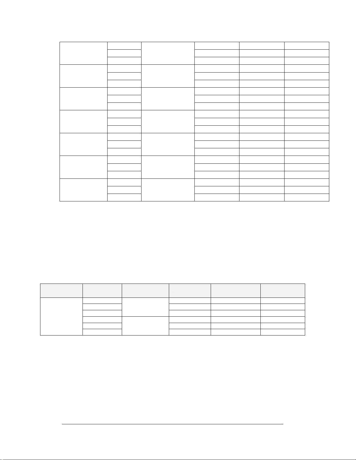
The following table refers to the information in Drawing B-91012
2-2 New Track
Installation
Page 17
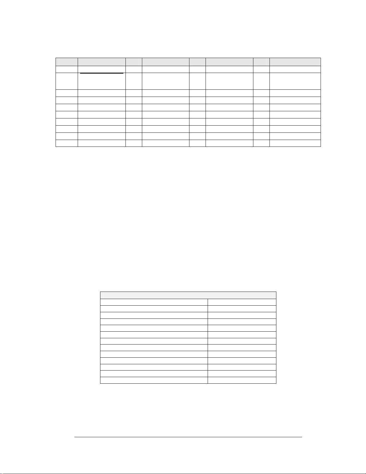
Infrared Photocells
Item Part No. # Part No. # Part No. # Part No.
1 0A-1067-0128 11 W-1267 21 0A-1067-0108 31 Incl. w/item #28
2
Incl. w/item
12 W-1117 22 0A-1067-0111 32 A-1157
#1
3 A-1305 13 0A-1067-0099 23 0A-1067-0064 33 0A-1081-0016
4 A-1157 14 0A-1067-0100 24 0A-1067-0065 34 Custom
5 W-1239 15 W-1399 25 0A-1067-0063 35 Custom
6 0A-1067-0076 16 0A-1067-0010 26 W-1117 36 0A-1067-0143
7 W-1266 17 0A-1081-0146 27 0A-1067-0080 37 W-1117
8 W-1266 18 W-1237 28 0A-1067-0050 38 EC-1082
9 W-1264 19 0A-1067-0107 29 W-1350 39 A-1078
10 W-1267 20 0A-1067-0071 30 A-1305 40 Custom
2.6 Location Requirements
Reference Drawings:
Field Cabling; C-44 Timer...........................................................Drawing B-75554
This section explains the equipment locations on the track for best operation. Such topics as
conduit, power and electrical requirements, noise levels, and other location considerations are
discussed. Daktronics recommends that these guidelines be followed as closely as possible.
Signal Conduit and Cable
All cable should be 18 awg twisted shielded pair, Beldon 8760 (Dak W-1117) unless
noted. All cable should be in conduit. Refer to Drawing B-75554 for conduit sizes and
cable types.
Power
The following is a list of electrical items and their respective power requirements.
Unit Power Requirement (Watts)
Start line outlet 100
Tower outlets 1800
C-44 console 100
Color monitor (C-44) 114
Isolation interface 30
Printer (log or time slip) 30
Time slip printer booth outlet 84
60 ft. line outlet 200
1/8th mile line outlet 30
Starters box interface 100
Color monitor (results) 102
DAKTRONICS 486DX computer 100
Three-amber tree 2000 (min 20 amps)
New Track 2-3
Installation
Page 18

Electrical
All electrical equipment used in the timing system runs on standard 120 Volts AC/60 Hz.
Noise (Radio/PA)
Important: The C-44 data cables must never be run with AC (power) or PA (Public
Address) cables. The data cables may cross AC or PA cables when absolutely
necessary but only at 90-degree angles. If it is necessary to run AC or PA cables
parallel to a data able, the cables must not be closer than 24".
In addition, care must be taken to insure that radio transmitters or television high
voltage transmitters are far enough from the track to prevent noise interference. If
these transmitters are close to the track, all cable must be shielded to prevent
interference.
Care must be used to insure that the cable not be crimped or bent into too tight a
radius. If it is necessary to put bends in conduit, they should be sweeping nineties.
Grounding
All equipment used with the timing system must be properly earth grounded. Make
sure all outlets and cords are three-conductor (grounded). All extension cords or
extra wiring must be three-conductor as well.
Important: Check to be sure that the service entrance (for the power) is properly
earth grounded. If it is not grounded, have it properly grounded.
Isolated Power Circuits
Daktronics recommends that the control equipment (i.e. C-44 console) be on a
dedicated power circuit to prevent noise interference. Air conditioners, fans, or highpowered electrical equipment may cause noise interference or a brown-out which
would reset the system.
Electrical Code
The National Electrical Code and all local codes must be followed when installing
electrical equipment. It is the responsibility of the installer to see that this is done.
Equipment damage or personal injury can occur if these codes are not followed.
2.7 Mounting and Locating Equipment
Reference Drawing:
Isolation Inter. Encl. Detail.......................................................... Drawing A-56253
Photocell Mnt. Dist. Dia. ............................................................. Drawing A-56354
Starter’s Box Interface................................................................ Drawing A-72242
Layout w/AC cells, st. ln. J-bx &C44CE...................................... Drawing B-91012
Field Cabling for dwg. B-91012 ................................................ Drawing B-114631
This section will explain how and where the track equipment should be mounted for a 1/8th
and 1/4th mile track. The distances for track setup are national standards and should be
followed.
2-4 New Track
Installation
Page 19

Intermediate and Speed Trap Distances
Refer to Drawing A-56354. With guard beam, the start line is the guard beam line and
all points should be measured from there. Without guard beam, the start line is the stage
line and all points should be measured from there.
Four different speed trap lengths can be used with the C-44. Each one starts at a different
point. Find the length to be used in the list below and mount the start of speed trap
photocells that same distance before the finish line. General practice is to use the 66'
speed trap.
Possible speed trap lengths: 2' 7-11/16"
13' 2-3/8"
66' 0"
132' 0"
Burn-out Box = 90 ft. from designated box to start line.
Photocells
Roll Out- Height of the beams must be adjusted as necessary, to provide 12" of roll
using standard dragster wheel/tire (22" diameter). Beam height must be low enough to
accommodate clearance rulings.
Infrared Photocell Mounts
Mounting- The photocell stands can mount to either the protective guard rail or
directly to a concrete surface. Ensure that the mount is level both horizontally and
vertically to ensure proper photocell alignment. Photocell mounts are equipped with
slots for side to side and up and down alignment.
Photocell Mounting
Mounting- Photocells with pipe mounts must be attached so the photocells are
secure. The 60' photocell must be 10 1/2 inches above the crest of the track. All
other interval photocells (i.e. 1/8th mile, speed trap, etc.) must be six inches above
the crest of the track.
Tree Mounting Considerations
The distance from the start line to the tree must be 38 to 40 ft. The height of the tree
should be 80 inches from the ground to the center of the pre-stage bulb.
Time Slip and Logging Printer Considerations
The Time Slip and logging printers will be Epson LX-300's standard. Locate the printers
as shown in the system diagram (refer to Drawing B-91012). Care should be taken when
choosing a site that can keep the printer from getting wet. The Time Slip printer cable
can be routed with the finish line cable or scoreboard cables. Note: The E.T. printer
requires two 18 awg twisted shredded pairs, Beldon 8760 (Dak W-1117). The shield
should only be connected to earth in the control tower.
Starters’ Box Interface Mounting
Refer to Drawing A-72242 for an example of the starters box interface. The starters box
interface has transmit and receive lines hard-wired between the starters box and isolation
interfaces, and it is hardwired to the start line for the starters console. J2, located on the
starters box interface, is an optional place to plug in the starters console. The starters box
interface is located in the control tower as shown in Drawings B-114631 and B-91012.
New Track 2-5
Installation
Page 20

Isolation Interface Mounting
The isolation interface is designed with all field cabling connections made with clamping
screw plugs, and all tower cabling connections made with supplied, D-type connector
cables. Field equipment which must be connected to the isolation interface includes all
photocells, all start-line equipment via the start line junction box, time slip printer, and
ET/MPH displays.
Mounting considerations consist of access to all previously mentioned field cabling,
proximity to C-44 timer (all interconnects made with standard 10' cables), position C-44
timer operator unrestricted view of isolation interface LED indicators, and adequate
clearance for any high traffic areas. An ideal mounting location would allow the C-44
operator to view both the C-44 monitor and the isolation interface front panel, yet not
restrict maintenance access (as depicted in Drawing A-56253). Refer to Drawing B-
91012 for suggested tower equipment location.
2.8 Field Wiring
Reference Drawings:
Iso. Interface Term Blk. Detail .................................................... Drawing A-56252
Iso. Interface Encl. Detail............................................................ Drawing A-56253
Start Box Int. Wiring.................................................................... Drawing A-72242
C-44 Start Line J-Box ................................................................. Drawing A-75431
Field Cabling; C-44 Timer........................................................... Drawing B-75554
Lay. w/AC clls,stlnJ-bx&C44CE.................................................. Drawing B-91012
Field Cabling for dwg B-91012 ................................................. Drawing B-114631
This section pertains to the field wiring of the drag strip. The wiring will be done as followsstart line, intermediate, finish, and then tower. For all wiring, refer to the system diagram and
pay close attention to the field cabling diagram Drawing B-75554.
When making connections, make sure all equipment power is off!
Photocell Connection: Connect all photocells (except the start line photocells) in this
manner. Photocells are connected to the cables as per wiring instruction found in the power
board box.
Daktronics uses only 18 awg twisted shielded cable, Beldon part #8760 (Daktronics part #W-
1117) unless specified. The shield conductor provides protection from electrical noise and
interference. To provide proper protection, the shield conductor must be terminated at the
isolation interface end only. The field end of the shield should be cut back even with the outer
insulation of the cable and wrapped with an electrical insulation tape. When wiring
photocells to isolation, always jumper the unused photocells from positive to negative on
the isolation interface.
Start Line/Isolation Interface Wiring
The start line wiring consists of wiring the isolation interface, the start line junction box,
starter’s box interface, start line photocells, and the guard beam (optional).
Cables coming into the tower should come to the isolation interface. Refer to Drawings
A-56252, A-56253, A-72242, A-75431, B-91012, and B-114631 to aid in wiring.
2-6 New Track
Installation
Page 21
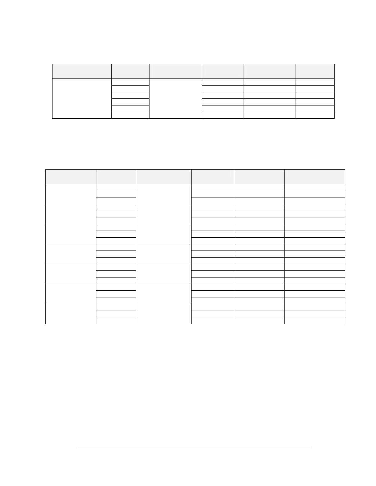
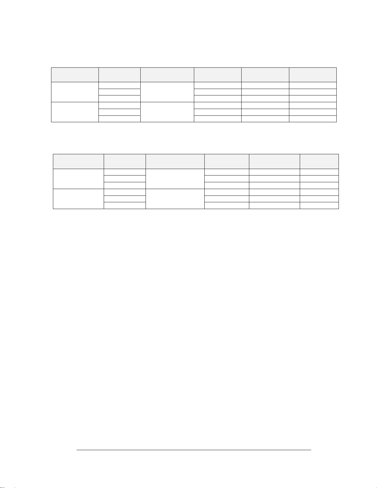
Isolation Interface to Starters Box Interface Wiring
Description Form (I/I)*
TB 13-1 Red Trans + Rec-P
Isolation Interface/
Start line Interface
Communications
TB 13-2 Black Trans - Rec-N
TB 13-3 Shield Not Connected Earth
TB 13-4 Green Rec + Trans-P
TB 13-5 White Rec - Trans-N
TB 13-6
Specifications
Manhattan u4473
(Dak W-1234)
*Isolation Interface Drawing A-56252
**Start Line Interface Drawing A-72242
Isolation Interface to Start Line J-Box
Description From (I/I)* Cable
Specification
Pre-Stage
Left Lane
Stage Left Lane
Guard Left Lane
Pre-Stage Right
Lane
Stage Right Lane
Guard Right Lane
Tree Signal
TB7-1 Red TB3-1 LPSTAGEPCL-P
TB7-2 Black TB3-7 LPSTAGEPCL-N
TB7-3
TB7-4 Red TB3-2 LSTAGEPCL-P
TB7-5 Black TB3-7 LSTAGEPCL-N
TB7-6
TB7-7 Red TB3-3 LGUARDPCL-P
TB7-8 Black TB3-7 LGUARDPCL-N
TB7-9
TB1-1 Red TB3-4 RPSTAGEPCL-P
TB1-2 Black TB3-8 RPSTAGEPCL-N
TB1-3
TB1-4 Red TB3-5 RSTAGEPCL-P
TB1-5 Black TB3-8 RSTAGEPCL-N
TB1-6
TB1-7 Red TB3-6 RGUARDPCL-P
TB1-8 Black TB3-8 RGUARDPCL-N
TB1-9
TB16-1 Red TB1-1 SIG3-P
TB16-2 Black TB1-2 SIG3-N
TB16-3
Beldon 8760
(Dak W-1117)
Beldon 8760
(Dak W-1117)
Beldon 8760
(Dak W-1117)
Beldon 8760
(Dak W-1117)
Beldon 8760
(Dak W-1117)
Beldon 8760
(Dak W-1117)
Beldon 8760
(Dak W-1117)
Refer to the Operational Check (Section 2.8) for connection and power up procedure.
*Isolation Interface
**Start Line Junction Box
Note: If field cabling for guard beam photocells is present, but guard beam
photocells are not used, do not connect unused guard beam cabling to the isolation
interface terminal blocks (TB7-7, TB7-8, TB7-9, LGUARDPCL, and TB1-7, TB1-8,
TB1-9, RGUARDPCL).
Cable
Wire Color To (SLI)** Function
N.C. Not Connected Earth
Wire Color To (SLJB)** Function
Shield No Connection Shield-N
Shield No Connection Shield-N
Shield No Connection Shield-N
Shield No Connection Shield-N
Shield No Connection Shield-N
Shield No Connection Shield-N
Shield No Connection Shield-N
New Track 2-7
Installation
Page 22
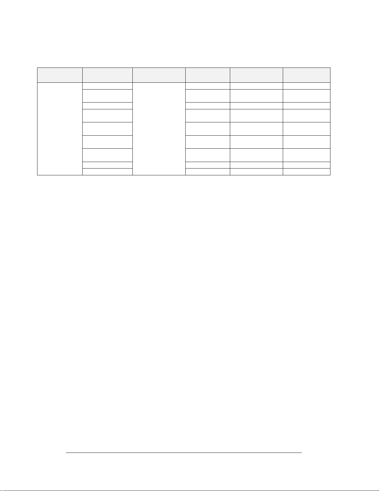
Start Line Interface from Start Line J- Box
Description To (SLI)* Cable
Specifications
Cable From
SBI to SLJB for
Hand-held
Starters
Console
+12V Yel Pair 5 TB2-1 +12V-P
L-Pro Tree Black Pair 1 TB2-2 PROTREE light
L-Ready Red Pair 1 TB2-3 Ready light –N
L-Times Reset Brn Pair 6 TB2-4 Timer Reset
S-STARTGO Blu Pair 4 TB2-5 GO/Reset
S-EMERG Grn Pair 3 TB2-6 Emergency
S-SINGLE Wht Pair 2 TB1-3 Singles/Drag
GND Black Pair 2 TB1-4 GND-N
SHIELD
Beldon 9774
(Dak W-1399)
*Start Line Interface Drawing A-72242
**Start Line J-Box Drawing A-75431
Start Line Photocells
The cable used for connecting the start line photocells to the start line junction box
(spreader cable) is pre-marked showing which photocell it connects to. Connect the cable
to the photocells as marked.
Installation of the Three-Amber Tree
The Daktronics three-amber tree is totally compatible with all Daktronics C-44 race
controllers. To install the three-amber tree, connect the tree cables into the connector on
the bottom side of the tree. Plug the AC power cord into an outlet capable of supplying a
minimum of 20 amps.
Regulations stipulate that the pre-stage bulb should be approximately 80 inches from the
ground; a longer mounting pipe will be necessary in some cases.
Eight, 60-watt yellow "bug" lights should be used for the stage and pre-stage lamps.
(There are two bulbs for each stage and pre-stage position to prevent confusion should
one bulb burn out.) The twelve amber, four green, and four red lamps should be standard
85-watt colored flood lamps (GE part #13472 red, #13474 green, #13463 amber). These
should be installed in the sockets using the supplied gasket to provide adequate bulb
support and moisture protection. The gaskets should be used with the lamp sockets to
seal and prevent vibration. The blue Sure Start lamp (if used) may be any blue-colored
reflector-type bulb rated at 100 watts or less.
Due to the increased power consumption of this starting tree, it is essential that the tree be
connected to a power supply sufficient to supply a minimum 20-amp current at the outlet.
If the power available is insufficient, some slight dimming of the staging lamps will be
noticed. This will not harm the tree, but the use of long extension cords should be
avoided. Refer to Section 4.2 for details on maintenance.
Intermediate Wiring (Optional) and Finish Line
This section consists of wiring the intermediate section of the track and the finish. This
includes the 60 foot (I 1), the 330 foot (I 2), the 1/8th mile speed trap (I 3), the 1/8 mile
finish, the 990 foot (I 4), and the 1/4 mile speed trap/finish.
Wire Color From (SLJB)** Function
–N
light-N
switch-N
switch-N
switch-N
SHIELDS Not Connected EARTH
2-8 New Track
Installation
Page 23

Intermediate One, 60'- Wiring between the isolation interface and the 60' photocell Jboxes use multiple one pair shielded 18 awg cable. Plugs with clamping screws are used
for connection to the isolation interface. Refer to the following connection table to assist
in the installation. You may also reference the field cabling diagrams (Drawing B-
91012 and B-114631).
Intermediate Two, 330'- Wiring between the isolation interface and the 330' photocell J-
boxes use multiple one pair shielded 18 awg cable. Plugs with clamping screws are used
for connection to the isolation interface. Refer to the following connection table to assist
in the installation. You may also reference the field cabling diagrams (Drawings B-
91012 and B-114631).
1/8 mile, 660' (Speed Trap)- Wiring between the isolation interface and the 660' speed
trap photocell J-boxes use multiple one pair shielded 18 awg cable. Plugs with clamping
screws are used for connection to the isolation interface. Refer to the following
connection table to assist in the installation. You may also reference the field cabling
diagrams (Drawings B-91012 and B-114631).
Intermediate 990'- Wiring between the isolation interface and the 990' photocell J-boxes
use multiple one pair shielded 18 awg cable. Plugs with clamping screws are used for
connection to the isolation interface. Refer to the following connection table to assist in
the installation. You may also reference the field cabling diagrams (Drawings B-91012
and B-114631 in Section 2.5).
1/4 mile, 1320' (Speed Trap)- Wiring between the isolation interface and the finish line
photocell J-boxes use multiple one pair shielded 18 awg cable. Plugs with clamping
screws are used for connection to the isolation interface. Refer to the following
connection table to assist you in the installation. You may also reference the field cabling
diagrams (Drawings B-56301 and B-114631).
Description To (I/I)*
TB8-1 Red J1-1 SIGNAL-P
60N Left Lane
60N Right Lane
330N Left Lane
330N Right Lane
Start of Speed
Trap #1 Left Lane
(594N)***
Start of Speed
Trap #1 Right
Lane (594N)***
1/8 Mile Left
Lane (660N)
TB8-2 Black J1-3 GND
TB8-3
TB2-1 Red J1-1 SIGNAL-P
TB2-2 Black J1-3 GND
TB2-3
TB8-4 Red J1-1 SIGNAL-P
TB8-5 Black J1-3 GND
TB8-6
TB2-4 Red J1-1 SIGNAL-P
TB2-5 Black J1-3 GND
TB2-6
TB9-1 Red J1-1 SIGNAL-P
TB9-2 Black J1-3 GND
TB9-3
TB3-1 Red J1-1 SIGNAL-P
TB3-2 Black J1-3 GND
TB3-3
TB9-4 Red J1-1 SIGNAL-P
TB9-5 Black J1-3 GND
TB9-6
Cable
Specifications
Beldon 8760
(Dak W-1117)
Beldon 8760
(Dak W-1117)
Beldon 8760
(Dak W-1117)
Beldon 8760
(Dak W-1117)
Beldon 8760
(Dak W-1117)
Beldon 8760
(Dak W-1117)
Beldon 8760
(Dak W-1117)
Wire Color From (Cell)** Function
Shield Not Connected EARTH
Shield Not Connected EARTH
Shield Not Connected EARTH
Shield Not Connected EARTH
Shield Not Connected EARTH
Shield Not Connected EARTH
Shield Not Connected EARTH
New Track 2-9
Installation
Page 24
1/8 Mile Right
Lane (660N)
990N Left Lane
990N Right Lane
Start of Speed
Trap #2 Left Lane
(1254N)***
Start of Speed
Trap #2 Right
Lane (1254N)***
1/4 Mile Left
Lane (1320N)
1/4 Mile Right
Lane (1320N)
TB3-4 Red J1-1 SIGNAL-P
TB3-5 Black J1-3 GND
TB3-6
TB9-7 Red J1-1 SIGNAL-P
TB9-8 Black J1-3 GND
TB9-9
TB3-7 Red J1-1 SIGNAL-P
TB3-8 Black J1-3 GND
TB3-9
TB10-1 Red J1-1 SIGNAL-P
TB10-2 Black J1-3 GND
TB10-3
TB4-1 Red J1-1 SIGNAL-P
TB4-2 Black J1-3 GND
TB4-3
TB10-4 Red J1-1 SIGNAL-P
TB10-5 Black J1-3 GND
TB10-6
TB4-4 Red J1-1 SIGNAL-P
TB4-5 Black J1-3 GND
TB4-6
*Isolation Interface
**Intermediate/ Finish Line Photocell J-Box
*** Based on a 66 Ft Speed Trap
Time Slip Printer/Printer Interface Wiring
The Time Slip Printer is a 40 column Epson TM-4200 or an Epson LX300 (contact
Daktronics for other choices or models). The Time Slip Printer is then plugged into a
Printer Interface. The printer interface has a terminal block (TB1) to connect to the cable
coming from the isolation interface. Refer to the following table for connecting the cable
to the isolation interface. Use two, shielded 18 awg pair cables. You may also reference
the field cabling diagrams (Drawings B-91012 and B-114631).
Description From (I/I)* Cable
Specification
Time Slip
Printer
TB14-1 Red TB1-4 ETFAULT-P
TB14-2 Black TB1-5 ETFAULT-N
TB14-3
TB14-4 Red TB1-1 ETDATA-P
TB14-5 Black TB1-2 ETDATA-N
TB14-6
Beldon 8760
(Dak W-1117)
Beldon 8760
(Dak W-1117)
*Isolation Interface
Optional: Wiring Between the Isolation Interface and Scoreboards
Wiring between the isolation interface and the scoreboards/dial-in displays use multiple
one pair 18 awg shielded cables. Refer to the following wire connection table to assist in
the installation. You may also reference the field cabling diagrams (Drawings B-91012
and B-114631).
Beldon 8760
(Dak W-1117)
Beldon 8760
(Dak W-1117)
Beldon 8760
(Dak W-1117)
Beldon 8760
(Dak W-1117)
Beldon 8760
(Dak W-1117)
Beldon 8760
(Dak W-1117)
Beldon 8760
(Dak W-1117)
Wire Color To (Printer
Shield Not Connected EARTH
Shield Not Connected EARTH
Shield Not Connected EARTH
Shield Not Connected EARTH
Shield Not Connected EARTH
Shield Not Connected EARTH
Shield Not Connected EARTH
Function
Interface)
Shield Not Connected Earth
Shield Not Connected Earth
2-10 New Track
Installation
Page 25
Isolation Interface to Left Scoreboard Wiring List
Description From (I/I)* Cable
Specifications
Left Lane SCBD
Left Lane Dial-in
Display
TB15-1 Red TB31-1 SIG1-P
TB15-2 Black TB31-2 SIG1-N
TB15-3
TB15-1 Red Tip SIG1-P
TB15-2 Black Ring SIG1-N
TB15-3
Beldon 8760
(Dak W-1117)
Beldon 8760
(Dak W-1117)
*Isolation Interface
Isolation Interface to Right Scoreboard Wiring List
Description From (I/I)* Cable
Specifications
Right Lane SCBD
Right Lane Dial-
In Display
TB15-4 Red TB31-1 SIG2-P
TB15-5 Black TB31-2 SIG2-N
TB15-6
TB15-4 Red Tip SIG2-P
TB15-5 Black Ring SIG2-N
TB15-6
*Isolation Interface
Beldon 8760
(Dak W-1117)
Beldon 8760
(Dak W-1117)
Wire Color To (Left
Function
Scbd)
Shield Not Connected Earth
Shield Not Connected Earth
Wire Color To (Right
Function
Scbd)
Shield Not Connected Earth
Shield Not Connected Earth
2.9 Operational Check
Reference Drawing:
Printer Interface Assy..................................................................Drawing A-65810
C-44Start Line J-Box...................................................................Drawing A-75431
Field Cabling; C-44 Timer.........................................................Drawing B-114631
During the operational check, the final connections are made on the system and preliminary
tests are done to determine if all the equipment is working properly. First, the equipment in
the tower is checked, then the start line, the intermediate equipment, and finally, the finish
line.
Timer - Monitor - Keyboard - Isolation Interface
This section will cover the connection of the equipment in the tower. Refer to the system
diagram and cabling diagram for information on the items that connect to the C-44. Refer
to Drawing A-65810 to view the back panel of the C-44.
Connect the cable that came with the video monitor to the "VIDEO BOARD
(VIDEO 1)" port on the back of the C-44. The power switch is on the lower
right side of the monitor.
Connect the cable that came with the keyboard to the "KEYBOARD" port.
Plug the C-44 and the monitor into a tower outlet. Other equipment will be
connected as the system is turned on.
Make sure the timer and monitor are plugged in. Turn on the power to the C-44
and monitor. Check to be sure the green power LED lights up when turned on
and the fan in the rear of the console is moving air. Make sure a clear picture of
New Track 2-11
Installation
Page 26

the C-44 main screen appears on the monitor (Refer to Figure 1 in Section 3).
Some adjusting of the monitor brightness or focus may be necessary.
Use the keyboard to type in sample drivers' names, etc. to test if the keyboard is
operating properly. Next, connect the equipment using the following
instructions.
Using one of the 9-pin "D" cables, connect the isolation interface port marked
“SLEB” to the C-44 port marked "COM1."
Using the other 9-pin "D" cable, connect the isolation interface port marked "ET
Printer" to the C-44 port marked "ET PRINTER (COM3)."
Using the 15-pin "D" cable, connect the isolation interface port marked
"DISPLAY" to the port marked "DISPLAY TRANSMITTER (DISPLAY1)."
Using the two 37-pin "D" cables, connect the isolation interface ports marked
"LEFT PHOTOCELLS" and "RIGHT PHOTOCELLS" to the C-44 ports
marked "PHOTOCELL BOARD #1 LEFT LANE (PHOTO1)" and
"PHOTOCELL BOARD #2 RIGHT LANE (PHOTO2)" respectively.
Connect the logging printer cable into the port marked "LOGGING PRINTER
(LPT1)" on the back of the C-44; connect the other end to the logging printer.
Refer to the printer user’s manual for instructions on how to insert the paper (8
1/2" by 11" white paper with tear-off edges should be used).
Optional: If a results system is being used, connect the results system cable to
the port marked "RESULTS (COM2)" on the back of the C-44 and the serial
port of the results computer.
For best results in protecting against glitches in the timing system, it is
recommended that a UPS power supply be attached to the timer and results
computer. For areas with irregular power supplies, a line voltage regulator is
recommended in conjunction with the UPS.
Timer - Start Line - Emergency
Connecting the starter’s box interface and start line junction box (Refer to Drawing A-
75431).
Plug in the power cord to starter’s box interface.
Connect the cable on the starter’s console into the connector on the start line
junction box.
The cable for connecting the start line junction box to the start line photocells is
a pre-marked spreader cable. Connect the start line photocell cable into the
military connector on the back of the start line junction box.
Emergency
To activate the emergency light, press the <F9> key while holding down the <CTRL>
key on the C-44 keyboard. Check to make sure that the red tree light comes on and that
the C-44 screen shows the emergency sign. Turn off Emergency by pressing
<CTRL><F9> a second time and reset the timer <SHIFT><F7>. Check the emergency
switch on the starter’s console. The emergency setting on the C-44 and the emergency
2-12 New Track
Installation
Page 27

switch on the starter’s console must be off to reset the timer. The switch on the starter’s
console marked emergency also turns the lights on and off.
Switch both to emergency mode. Test to be sure that the starter’s console cannot reset the
tree while the emergency light is on. Turn off the emergency switch on the starter’s
console. Now test the C-44 to make sure it cannot reset the timers. Now turn both
switches off and check to be sure the timer can be reset by the C-44.
Start Line Photocell Check
Use the photocell check function that is built into the isolation interface to check the
operation of the start line photocells. Refer to Photocell Check in 3.2 for instructions on
the use of the photocell check function.
Timer - Intermediate Photocell Check
Test the operation of the intermediate photocells and light sources. Use the photocells
check function as in Photocell Check in 3.2.
Timer - Win Lights - Finish Line Photocell Check
Use the Win Lights diagnostics function that is built into the C-44 to test the optional Win
Lights. Refer to <Ctrl-W> Win Light Diagnostics in Section 3.3 for instructions.
Use the photocell check function again to check the operation of the finish line
photocells. Now all photocells should be operational.
Printers
Before each race, ensure that the printers and timer are connected. Make sure both
printers are on and on-line. Check to be sure both printers are enabled. If “off” shows up
by either Log or Time Slip, refer to System Configuration Settings in Section 3.3 on
enabling them. If “not ready” shows up by Log or Time Slip, something is not working
right from the computer to the printer.
Scoreboards (Optional)
Use the scoreboard diagnostics function that is built into the C-44 to test the operation of
the scoreboards. Refer to <Ctrl-S> Scoreboard Diagnostics in Section 3.3 for
instructions on the use of the scoreboard diagnostics function.
Final Testing
Finally, drive a car down the track at constant speed and check the operation of the entire
system. Verify the accuracy of the times that are returned as well as the speeds.
2.10 Sighting Infrared Photocells
Follow the photocell alignment procedures that come with the photocells.
New Track 2-13
Installation
Page 28

Page 29

Section 3: C-44 Race Timer Operation
3.1 General Operation
Access to all of the race controller’s functions is through the function keys (<F1> through
<F12>) located along the top edge of the keyboard. Many of the function keys have more
than one purpose, which are accessed by using the function keys in conjunction with the
<SHIFT>, <CTRL>, or <ALT> keys. A table of all functions (Figure 7) is given in Help
Screen in Section 3.3 of this manual, or can be viewed from the race controller by pressing
the <F6> key (Help Screen).
Keystroke sequences associated with functions are given in parentheses throughout this
manual. If a function key is listed by itself, such as <F1>, that means that the <F1> key alone
is used to access that function. If a function key is listed with another key, such as
<SHIFT><F1>, the <SHIFT> key must be held down while the <F1> key is momentarily
depressed.
3.2 C-44 Race Controller Functions
Reference Drawing:
Starter’s Console.........................................................................Drawing A-57318
Power Button
The power button used to supply main power to the unit, is on the front of the C-44 race
controller. When the unit is connected to a proper power source and the switch is on, the
power LED will be illuminated.
When the system is powered up, the monitor should display the following screen (Refer
to Figure 1). Note: Some systems may be configured differently when powered up,
therefore each screen may show some subtle differences to the one shown here. It should,
however, be very close.
Figure 1: C-44 Main Screen
Entering Dial-ins
Entering dial-ins is just like entering numbers on a calculator. Just type in the number,
leading and trailing 0's are put in automatically. However, the decimal point must be
C-44 Race Timer 3-1
Operation
Page 30

entered by the user. There is also a maximum of two digits before and after the decimal
point. After entering the dial-in press the <ENTER> key.
Timers Reset
To reset the timers, use one of three possible keystroke combinations depending on the
desired reset options:
1. <CTRL><F6> is used to reset the timers for both lanes only.
2. <SHIFT><F7> is used to reset the timers for both lanes and move the next driver
information to current.
3. <CTRL><F8> is used to reset the timers for both lanes and move the next driver
information to current and cause the tower log printer and time slip printer to
output preceding race information. When both timers are reset, a timers reset light
on the starter's console will be illuminated, and a timer reset message will appear
for each lane on the monitor.
Tree Countdown Modes
<ALT><F5> is used to select the tree countdown mode. The selected countdown mode
will alternate between full tree and pro tree with each press of <ALT><F5>. The
countdown sequence and rate that are currently active are displayed below the left lane
portion of the main screen. This gives the operator constant verification of the
countdown mode. If the selected category has split tree on, the countdown mode of the
right lane will display below the right lane. The keystroke <SHIFT><F5> will alternate
the countdown mode for the right lane when in split tree and <ALT><F5> will change
the left lane. The exact countdown rate used is selected by pressing <CTRL><F1> to get
the Setup Parameters Menu, followed by <C> to access the Tree Countdown Mode
feature (Refer to Figure 9 in Section 3.3).
Sure Start
<ALT><F6> will put the timer in sure start mode. When in this mode, a foul will be
generated if a vehicle was not pre-staged at the instant the starter's switch was thrown to
GO. This feature allows a track operator to enforce the no deep staging rule.
When sure start is activated, the blue bulb on the starting tree between the stage lights
will be on, and “SS” is displayed in the lower left portion of the main screen. If
<ALT><F6> is pressed a second time, the sure start is turned off, the blue bulb is no
longer illuminated, and the SS indicator is off.
True Win/Breakout
The keystroke combination <ALT><F7> activates the True Win function and causes
“TW” to be displayed in the lower left portion of the main screen. The True Win
function allows the winner of a race to be determined based on the following factors.
A. General disqualifications (entered manually by the operator)
B. Crossing a lane boundary line (entered manually by the operator)
C. A foul (red light)
D. Crossing the finish line first
E. Not finishing the course (entered manually by the operator)
If True Win is activated, the Breakout function can be selected by pressing <ALT><F8>.
Breakout is activated and “BO” is displayed in the lower center portion of the main
screen, this allows the inclusion of E.T. breakouts into the determination of a winner.
When both True Win and Breakout are activated, the following factors are used to
determine the true winner:
3-2 C-44 Race Timer
Operation
Page 31

1. General Disqualifications (DSQ)- Disqualifications are infractions manually
entered by the operator <ALT><F1> (left lane) or <ALT><F9> (right lane).
These include unsportsmanlike conduct, intentional delay of run, and others as
determined by the officials. The C-44 handles DSQ's in the following way. If
one driver is disqualified, the other driver automatically receives the win. If
both drivers are disqualified, the driver with the least severe infraction wins the
race. To determine the severity of an infraction, see the race officials.
Infractions may be canceled manually by the operator: <ALT><F4> (left lane)
or <ALT><F12> (right lane).
2. Crossing Lane Boundary Lines (OB)- Leaving lane boundary lines is an
infraction of the rules. If the operator is notified that a driver has left the driving
lane, the operator enters an out-of-bounds (OB) <ALT><F2> (left lane) or
<ALT><F10> (right lane). The driver who leaves the driving lane is
disqualified, the other driver automatically wins even if his or her car leaves the
driving lane during the remainder of the race, unless a more severe infraction
occurs.
3. Fouls (red lights)- A foul (or red light) is caused when a driver crosses the
starting line before the green light is on (negative reaction time). The C-44
automatically senses a foul, if one has occurred. When a foul does occur, the
driver who fouled is disqualified and the other driver receives the win. If both
drivers foul, the driver who fouled first loses the race. Note: When Sure Start is
active and both drivers foul, both are disqualified in accordance with the no deep
staging rule mentioned earlier.
4. E.T. Breakouts- A breakout occurs when the driver beats his or her respective
dial-in. The C-44 automatically detects breakouts. When a breakout occurs, the
driver who “broke-out” is disqualified and the other driver receives the win. If
both drivers breakout, the driver who “broke out” by the least amount of time
receives the win. If both breakouts are equal the driver that crossed the finish
line first is the winner.
5. Which Vehicle Crossed the Finish Line First- The C-44 automatically
determines which driver finishes the race first. This determination is used to
decide the winner when two drivers have equal dial-ins and no other infractions
occur, or when a double breakout of equal time occurs.
6. Not Finishing the Course (DNF)- If a driver does not finish the course, the C44 operator manually enters a did-not-finish (DNF): <
<ALT><F11> (right lane). The driver who did not finish the race loses the race.
If both drivers do not finish, both drivers are given losses.
Both True Win and Breakout are deactivated by pressing their respective
keystroke combinations a second time.
ALT><F3> (left lane) or
Emergency
<CTRL><F9> will activate the flashing red lights on the tree and inhibit any countdown
of the tree. An emergency message on the monitor will also flash. Press <CTRL><F9>
a second time to deactivate the emergency mode.
There is also an emergency switch on the starter's console (Drawing A-57318), which
will also activate the emergency mode. The emergency mode will rema in active until
both the keyboard select on the C-44 and the switch on the control box are off.
C-44 Race Timer 3-3
Operation
Page 32

Altitude Adjustment
An Introduction to Altitude Adjustment
Many race car engines run better, and consequently the cars move faster, when the
air available to the engine is denser. In general, cars will run faster at sea-level
tracks than at high elevation tracks such as in “mile high” Denver. The drag racing
industry has developed lists of altitude correction factors that can be used to adjust
E.T. and MPH values for races that are run at various altitudes. The basic concept is
to adjust the E.T. and MPH values that are experienced at the higher elevation tracks
to sea-level values so that all results can be directly compared.
In the past, the E.T. and MPH values had to be manually adjusted using the altitude
correction factor when preparing a timer for a race or verifying the results. The
altitude adjustment feature of the C-44 timer allows this operation to be performed
automatically by the timer to prevent errors and allow quicker verification of race
results. The C-44 also allows the automatic altitude adjustment function to be
quickly switched off if manual calculations are desired or if the altitude correction
factors are not used for some races.
The C-44 system allows three sets of adjustment factors to be entered by the
operator. Each set contains one factor for adjusting the E.T. and one factor for
adjusting the MPH. This allows different categories of classes to have different
adjustment factors pre-entered and quickly available for each race. The
determination and accuracy of the actual factors used are the responsibility of the
track operator and the track’s sanctioning body.
Altitude Adjustment Example
Figure 2 shows the results of a race that was run using the altitude adjustment factors
of the C-44.
Figure 2: Altitude Adjustment Example
1. Notice at the bottom of the screen: Altitude adjustment feature is turned on
("ADJ"). Adjustment factor set #1 is selected. This factor set has an E.T. factor
= 1.0000 and speed factor = 1.0000.
2. Dial-ins were entered as sea-level dial-ins. Dial-ins of 10.25 for the left lane and
10.17 for the right lane were entered.
3. The C-44 automatically divides the sea-level dial-in by the E.T. adjustment
factor to produce an actual (at altitude) elapsed time value that will be used to
3-4 C-44 Race Timer
Operation
Page 33

determine the tree handicap. This at altitude elapsed time value is shown on the
screen after the word “Hdcp” for each lane.
4. As the race is run, the C-44 multiplies the actual measured at altitude times by
the E.T. adjustment factor to produce the sea-level times for:
- Reaction Time
- Interim 1 Time
- Interim 2 Time
- Interim 3 Time
- Interim 4 Time
- Final E.T.
5. The actual at altitude MPH which is calculated in the speed trap by the C-44 is
multiplied by the MPH adjustment factor to produce sea-level MPH.
6. Note that all the times and MPH shown on the monitor, scoreboard, and
printouts are sea-level values. Most drivers and spectators are familiar with the
sea-level values which are also listed in most racing publications.
7. Note that the values in the E.T. printout (Figure 3) are marked with A1 to show
that they are sea-level values that have been calculated from the actual at
altitude values using altitude adjustment factor #1. This is also true for the log
slip (Refer to Figure 4).
Figure 5 shows the results of an identical race that was run without using the altitude
adjustment feature.
C-44 Race Timer 3-5
Operation
Page 34

Note: The dial-ins were manually adjusted before being entered. The times and
MPH shown are the actual unadjusted at altitude values that were read by the C-44
timer.
WELCOME TO THUNDER VALLEY'S 1993 FINALE
"$1,000 BRACKET BONANZA BASH"
TASTE IT NOW? BUDWEISER AND PEPSI-COLA
THANKS FIRESTONE / CENTERLINE E.T. RACING SERIES
11/23/94 13:49
------------- LEFT LANE ----------------------------- RIGHT LANE------------- 44 357
Dial-in :10.25Dial-in :10.17
Reaction: 0.172Reaction: 0.113
I1 : 1.172<A1>I1 : 1.347<A1>
I2 : 6.891<A1>I2 : 6.673<A1>
I3 : 7.412<A1>I3 : 7.213<A1>
MPH (I3):85.42 <A1>MPH (I3):86.21 <A1>
I4 : 9.321<A1>I4 : 9.118<A1>
E.T. :10.311<A1>E.T. :10.262<A1>
MPH :91.43<A1> MPH : 93.68<A1>
Over/Under: .061Over/Under: .092
WIN <1ST>
PRO SS-N TW-Y BO-N PRO SS-N TW-Y BO-N
Figure 3: Time Slip Printout Showing Adjustment Factors
CATEGORY #1
ELIMINATION ROUND
8/13/93 13:45
Time Vehicle Number -DI-- --RT-- --I1-- --I2-- --I3-- --S1-- --I4-- --ET-- --SP-- --O/U-- Results Infractions
L
13:49 44
R
13:49 357
L-FULL R-FULL S.S.-N T.W.-Y B.O.-N
Figure 4: Log Printout Showing Adjustment Factors
A sometimes confusing effect of altitude adjustment corrections on handicap
calculations can also be shown with this example.
10.25 .172 1.172 6.891 7.412 85.42 9.321 10.311 91.43 .061
10.17 .113 1.347 6.673 7.213 86.21 9.118 10.262 93.68 .092 WIN (1st)
3-6 C-44 Race Timer
Operation
A1
A1
Page 35

Figure 5: Identical Race as in Figure 2, but without Altitude Adjustment
If the cars had been racing at an actual sea-level track with dial-ins of 10.25 and
10.17 respectively, the handicap would be 10.25 - 10.17 = 0.08 seconds. The
concept of altitude corrections assumes that both cars in the race will be affected to
the same percentage by the thinner air at altitude. Thus, both cars’ E.T.’s are
adjusted by the same altitude factor. The altitude E.T.’s are thus 10.41 and 10.32
respectively.
A fair race based on the altitude corrections concept, therefore, requires that the
resulting handicap at altitude will be 10.41 - 10.32 = 0.09 seconds.
Using Altitude Adjustment
To set the race controller for altitude adjustment, press <CTRL><F1> to get the
Setup Parameters menu, followed by <A> to access the Altitude Adjustment Factors.
The <TAB> or <ENTER> key is used to move the highlight bar to the Altitude
Adjustment On:__ line. Press the <SPACE BAR> to alternate between Yes and No.
Similarly, the Factor # can be selected by moving to the Factor: __ line and pressing
the <SPACE BAR> until the desired number is displayed.
Once the factor sets have been preset (Refer to <A> Altitude Adjustment Factors in
Section 3.3), they can be selected as described above. The current selection of
adjustment factors is displayed on the monitor. Also, an A1, A2, or A3 will be
printed on the time slip to indicate which adjustment factor set has been selected.
Using Dial-ins With Adjustment Factors
When a dial-in is entered, it is assumed to be a sea-level dial-in. This usually comes
from a published index or, in the case of E.T. racing, from the time slip of an earlier
altitude-adjusted time trial run.
For the tree handicap countdown, the sea-level dial-in that is entered for each lane is
divided by the current E.T. adjustment factor to give the proper handicap difference
based on the two cars performance at altitude. This insures a properly matched
handicap race. Since the E.T. used to determine breakouts is a sea-level E.T., it is
compared to the sea-level dial-in to determine if a breakout has occurred.
Note: The system does not allow any dial-in's greater than 99.99. Therefore, if an
adjusted dial-in figures to be greater than 99.99, the originally entered dial-in will be
used for the tree handicap.
C-44 Race Timer 3-7
Operation
Page 36

Reaction Timer
All reaction times are calculated from the start of the green light. A perfect reaction time
occurs when a car leaves the start line exactly as the green lamp lights. Negative or red
light reaction times are calculated backwards from the beginning of the green light. Refer
to Figure 27 in Section 3.3 for information on how the reaction time can be displayed.
Printers
The log printer and time slip printer may be enabled and disabled (Refer to <L> Tower
Log Printer and <P> Time Slip Printer in Section 3.3). If a printer is turned off or not
ready, the monitor will display a message to that effect in the lower right hand corner of
the screen. If a printer is off, the C-44 race controller will store a limited number of race
results (approximately 15). When the printer is once again enabled, the stored
information will automatically be printed out. Always verify that the printer is powered
up and all printer cables are connected correctly.
Reset Win Light
Press <CTRL><F5> to turn off all of the spectator Win Lights on the finish line
scoreboards. These lights will also automatically turn off after a preset amount of time.
This preset amount of time (selected manually by the operator) is called the Win Light
Format (W on the parameter setup menu, refer to <W> Win Light Format in Section
3.3). The Win Light Format can be set to either 5, 10, or 15 seconds.
Photocell Check
The push-to-test photocells switch on the lower right corner of the isolation interface
makes the photocells less sensitive, in order to verify that the cells are properly aligned.
If all the photocells are aligned properly, the letters denoting each cell will not appear on
the bottom of the screen and the corresponding LED’s on the isolation interface will be
lit. If a cell is not properly aligned or it is not working properly (i.e. the cell is not
receiving power) the letters for that cell will show up on the screen after the button is
pressed. If this occurs, these particular cells should be checked before the system is used.
Margin of Victory (MOV)
The Margin of Victory is the time between when the first car crosses the finish line until
the second car crosses. This time is displayed on the C-44 monitor on the track side of
the car that finishes first. This time is calculated by adding the reaction time to the
elapsed times for each lane and then adding any handicap time to the opposite lane. The
times are then subtracted to get the margin of victory. MOV is not displayed if there is a
Foul, a Breakout, or if True Win is off.
3.3 Additional Functions
Help Screen
The following illustration depicts the help screen that is called up on the monitor when
<F6> is pressed.
It is recommended that this page be reproduced and posted for the operator’s use.
Additional function descriptions appear on the following pages.
3-8 C-44 Race Timer
Operation
Page 37

Figure 6: C-44 Help Screen
Setup Parameters Menu
The Setup Parameters Menu <CTRL><F1>, illustrated below, is used to configure the
system before racing begins.
To select an item from the Setup Parameters Menu, press the key or key combination in
brackets <>. Following is a description of each of the options in the menu.
Figure 7: Setup Parameters Screen
<A> Altitude Adjustment Factors
The A option on the Setup Parameters Menu
is chosen when altitude adjustment factors
will be used. Type the E.T. factor for the first
set in a fixed decimal point format.
Be careful: Be sure the factor is entered
correctly (i.e. make sure the E.T. factor is
entered as 0.9xxx and not as 9.xxxx). By
using the space bar and backspace key, the
operator can move around within the factor
itself to make sure it is correct.
Figure 8: Altitude Adjustment
There are three sets of adjustment factors available, each set containing one (1) factor
for adjusting the E.T.'s and one (1) factor for adjusting the speed. Use the tab or
enter key to move from the E.T. factor to the next set, after the first factor is correctly
entered.
C-44 Race Timer 3-9
Operation
Page 38

Continue to make entries until all the desired factors have been entered. If no entry
is needed, just use the tab key to move to the next factor. Note: Although three sets
of factors are available, it is not necessary to use them all. If only one set is needed,
just enter that set and leave the others alone.
When all factors have been entered, press the <ESC> key to return to the Setup
menu.
<C> Tree Countdown Modes
There are many possible
combinations of sequences and rates
of countdown for the tree. The
following is a list of available
sequences and rates. They can be
used in any combination. The tree
delay is used to select a delay for
the use of LED trees. It can be set
from .00 to .05. If no delay is
needed it should be set to .00.
Pro Tree Sequences Rates
Instant Green
Pro (1 amber)
Pro (3 amber)
.2 sec
.3 sec
.4 sec
.5 sec
Figure 9: Combinations
Full Tree Sequences Rates
2 amber
3 amber
5 amber
3x amber
.2 sec
.3 sec
.4 sec
.5 sec
<D> Finish Line Distance
Option D is used to select the track length that the
timer will be configured for. The user may specify
a finish distance of:
1/4 mile
1/8 mile
Figure 10: Finish Line Distance
<E> Event and Sponsor
Information
From this menu, the track name, event
name, and two sponsor ad lines are
entered.
All information entered in this fashion
will be printed on each time slip. An
example of the time slip printout can be
seen in Figure 11.
Figure 11: Time Slip Information
3-10 C-44 Race Timer
Operation
Page 39

<F> Time Slip Format
Option F is used to change the format
of the time slips. The user has three
formats to choose from:
• Print two dual lane time slips.
• Print two single lane time slips.
• Print one dual lane time slip.
Figure 12: Change Format
<S> Set Scoreboard Enables
Option S is used to configure the
displays, and enable or disable the two scoreboards located at the finish line.
A particular time or value will be displayed only when a Y appears below it. Move
the highlight bar to the value that needs to be changed and press the <SPACE
BAR>. The display will alternate between Y and N. Similarly, the right and left
displays can be enabled or disabled by using the <SPACE BAR> to select On or
Off. Positioning the highlight bar under BRT and selecting [N] will cause the
displays to operate in a dimmed mode. Select [Y] to disable the dimming effect.
Figure 13: Configuration
<T> System Time and Date
Current system time and date are saved by
the C-44 when power is removed. In the
event that the operator wishes to correct
or change these settings this option may
be used to insure that all printouts have
accurate time and dates.
Figure 14: Time and Date
<W> Win Light Format
The Win Light timeout can be set to
either 5, 10, or 15 seconds.
Figure 15: Timeout
C-44 Race Timer 3-11
Operation
Page 40

<Ctrl-S> Scoreboard Diagnostics
To activate the scoreboard diagnostics program press <CTRL><S>. The screen will
show the numbers that are being sent to the respective fields on the scoreboard. If
there are parts of a number that are not lighting, either a bulb has to be replaced or
the scoreboard is not functioning properly. Refer to the scoreboard user’s manual for
instructions on troubleshooting.
Figure 16: Diagnostics
<Ctrl-W> Win Light Diagnostics
The Win Light diagnostics program can be activated by pressing <CTRL><W>.
The screen will show the sequence that the Win Lights should follow when they
light. If a Win Light does not light, either a bulb has to be replaced or the Win
Lights are not functioning properly. Refer to the scoreboard user’s manual for
instructions on troubleshooting the scoreboard.
Figure 17: Win Light Diagnostics
3-12 C-44 Race Timer
Operation
Page 41

System Configuration Settings
Figure 18: System Configuration Screen
The Configuration Menu <CTRL><F2>, illustrated here, contains basic system options
that are to be set prior to racing.
To select an item from the System Configuration Menu, press the key in brackets <>.
Following is a description of each of the options in the menu.
<T> Speed Traps
Option T is used to specify speed trap
lengths for both the interim 3 and finish line
speed traps. The operator may select from:
2.64 FT
13.2 FT
66.0 FT
132.0 FT
Figure 19: Speed Traps
<L> Tower Log Printer
Option L is used to specify the tower log printer
type. The user may select either Epson or C
Itoh. This option is also used to enable the tower
log printer by selecting Yes. Epson printers are
the only printers available from Daktronics.
<P> Time Slip Printer
Option P is used to specify the time slip
printer type. The user may select either
Epson, C Itoh, or EP40 (EP40 option is for
the TM-4200 40 column printer only). This
option is also used to enable the time slip
printer by setting the on line to Yes.
Figure 20: Log Printer
Figure 21: Time Slip Printer
C-44 Race Timer 3-13
Operation
Page 42

<E> Speed Format
Option E is used to select speed format. The user
may select either MPH or KPH.
<S> Scoreboards
Option S is used to specify scoreboard type. The
user may select from either single line or double
line.
Figure 22: Speed Format
<D> Dual Deep Stage
Option D is used to enable and disable the dual
deep stage rule in the C-44 configuration. With
this option enabled and the sure start function
on, the C-44 will indicate a foul even if the other
lane has fouled already.
Figure 23: Scoreboard Type
<R> Timer Reset Functions
Option R is used to configure the timer reset
functions.
When the auto timer reset is off, the starter cannot
reset the timer using the starter’s
console box. If it is on, the starter can
reset the timer at any time with the
starter’s console box.
The timer reset interlock function will
work only if the auto timer reset is set
to Off. When the timer reset interlock
is set to Off, the starter can activate the
tree at any time. If it is on, the starter
must wait until the timer has been reset
by the C-44 operator before starting the
tree countdown.
The printout function determines how the C-44 will work after a race is finished and
a printout is made. The user may select either:
Figure 25: Timer Reset
Figure 24: Dual Deep Stage
Printout only, or
Printout reset timer move next vehicle# to current
<H> No Tree Handicap
When No Tree Handicap is off, the timer will use
the dial-ins to get a handicap and the tree will
count down using the handicap.
When No Tree Handicap is on, the timer will not
use a handicap unless True Win is set On.
Figure 26: No Tree Handicap
3-14 C-44 Race Timer
Operation
Page 43

<A> Reaction Time
Display Type
Option A is used to specify a
zero-based reaction time or a
countdown rate-based reaction
time. With the tree countdown
rate-based reaction time, a perfect
reaction time corresponds to the
tree countdown rate currently
selected. For example, with a 0.3
sec countdown rate selected, the
perfect reaction time would be
0.300 sec. With zero-based
reaction time selected, a perfect reaction time would be 0.000 sec.
Figure 27: Reaction Time Display
<G> Auto Tree / No Stage Foul
When auto start of tree is on, the timer waits for the ready key <F5> to be pressed
and then waits for both lanes to be properly staged. Once both lanes are properly
staged, and the delay timer is started.
When the delay time has been reached, the tree countdown will be started. Burnouts
can be done by leaving Ready off until the racers are ready to stage. If a single car is
running on one lane, switch on the Starter’s Console the Drags switch to Singles,
then switch the Go switch to Go. When you do this, there is NO delay as the tree
counts down right away, so it effectively disables the auto tree for that single race
until the Starter’s Console is switched back to Drags.
Figure 28: Auto Start of Tree
If something happens when both lanes are staged, and the Ready key is pressed to
stop the delay timer, <CTRL><F6> must be pressed to reset the delay timer before
the Ready key is pressed again.
The delay time for auto start can be set for 1.0 to 3.9 seconds in .1-second
increments.
When Auto No Stage Foul is on, if one lane stages and the other lane does not stage
within the delay time, the tree will start its countdown for the staged lane and the
other lane will get a DNS foul (Did Not Stage). The staged lane gets the automatic
win. When this is set to off, the No Stage Foul will not operate. If auto tree is off,
the Auto No Stage Foul is automatically turned off.
The delay time for No Stage Foul can be set from 5 to 20 seconds in 1 second
increments. The Enable Reset/Go switch allows you to use the starters console for
the auto tree. If set to ON, the operator has to press the <F5> key to ready the auto
tree, except the tree will not begin it’s countdown until the starter’s console is
C-44 Race Timer 3-15
Operation
Page 44

switched to GO. That will start the delay tree countdown. Moving the switch to Reset
will stop the countdown at any time. If switched to off, the auto tree will function
normal using only the <F5> key
<B> Tie Break Selection
Figure 29: Tie Break Selection
Category Settings
The Category Menu
<CTRL><F3>, illustrated below,
allows the operator to preset
system parameters for up to 32
individual race categories.
During race operation the preselected settings may be enabled
simply by activating the proper
category. Following is a
description of each menu option.
<V> View
This function allows you to
decide the outcome of tie-run
races. The races can be
decided by the speed of the
racers, or the best reaction
time can be used to decide
the winner.
Figure 30: Category Settings Screen
To view the settings for an individual category, press <V> followed by the desired
category number then <ENTER>. Press any key to return to the Category Menu.
(Refer to Figure 30.)
<E> Edit
Press <E> to edit a category or begin a new category. Enter the number of the
category to be edited then <ENTER>. The current settings for that category will be
displayed. Individual items will be highlighted as they are selected for editing. To
advance to the next item, press <ENTER> or <TAB>. Press the <SPACE BAR> to
toggle the item through all possible settings. Press <ESC> at any time to save the
settings and return to the Category Menu.
Items which may be configured in the edit screen are described below.
Title- Category names are typed in via the keyboard. This allows the operator the
flexibility to customize category settings for any type of event.
Altitude Adjustment On- Setting this option to Yes will enable the altitude
adjustment function when the category is selected.
Factor- When altitude adjustment is enabled, one of three altitude adjustment factors
may be selected (the operator may configure the individual factors as described in
<A> Altitude Adjustment Factors in Section 3.3).
3-16 C-44 Race Timer
Operation
Page 45

Finish Line Distance- Race distance may be set to either 1/4 mile or 1/8 mile.
Split Tree- Selecting on for Split Tree will allow the selection of different tree
modes for each lane.
Tree Setting 1- To configure the tree choose a tree countdown mode and rate:
Pro Instant Green
Pro (1 Amber)
Pro (3 Amber)
Full 2 Amber
Full 3 Amber
Full 5 Amber
Full 3x Amber
.2 second
.3 second
.4 second
.5 second
Tree Setting 2- This second tree setting is for use with Split Tree and will be the
opposite of the first setting. If the first setting is Pro the second tree setting will be
Full. The one exception is if full 3x amber is selected the other tree will be full 3
amber.
The following 3 choices (Sure Start, True Win, and Break Out) are configured
separately for the qualification round and the elimination round.
Sure Start- To enable the sure start function for the category, select On. Select
Off to disable it.
True Win- To enable the true win function for the category, select On. Select
Off to disable it.
Break Out- To enable the breakout function for the category, select On. Select
Off to disable it.
Automatic Dial-in- To automate dial-in entry for those categories which require
all drivers to post the same specific dial-in, select Yes.
Value- The operator may enter the desired dial-in value to be used when the
automatic dial-in function is enabled. This dial-in value will be assigned to all
drivers when the category is selected.
The remaining choices allow the operator to select which split times and/or speeds
are to be displayed on the scoreboards and are configured separately for the
qualification round and the elimination round. To select a particular item to be
displayed, set the block below the item to Y. All items that are set to N will not
appear on the scoreboards, but are recorded and displayed on the control console
monitor.
Reaction time
RT
Intermediate 1 time
I1
Intermediate 2 time
I2
Intermediate 3 time
I3
Intermediate 4 time
I4
Elapsed time
ET
Dial-in
DI
Speed at 1/8 mile (if applicable)
S1
Speed at the finish line
SP
C-44 Race Timer 3-17
Operation
Page 46

<P> Print
Press <P> to create a printout of all 32 categories. This reference will be printed on
the tower log printer.
<S> Select
To select a category press <S> followed by the number of the desired category, then
<ENTER>. Choose either <Q> for qualification round or <E> for elimination round.
When a category has been selected, all system settings assigned to the selected
category will become active. In addition, the title and the round type will appear at
the bottom of the main screen, and the tower log printer will print a heading
indicating the category number, round type and date/time of selection (refer to
Figure 31). Press <ESC> to return to the main screen.
CATEGORY SETTINGS 01/28/94
---Title---
SUPER PRO
TOP FUEL
CATEGORY #5
TOP COMP
│
--Fact--
-
PRO (3 AMB) .4 SEC
--Alt
Adj--
YES #3 FULL 5 AMBER .2 SEC YES 10.11
NO #1 PRO (3 AMB) .4SEC NO
YES #1 PRO (3 AMB) .4 SEC YES 10.11
NO #1 PRO (3 AMB) .4 SEC NO
NO #1 full 2 AMBER .5 SEC YES 10.11
│
│
YES #1 PRO (3 AMB) .4 SEC YES 10.11
Figure 31: Category Selection
CATEGORY SETTINGS 01/28/94
---Title---
SUPER PRO
TOP FUEL
CATEGORY #5
TOP COMP
│
-
--RT-- -I1 -I2 -I3 -I4 -ET -D1 -S1 -SP --Elim Rnd-- -RT -I1 I2 -I3 -I4 -ET -D1 -S1 -SP
Qual
Rnd
Y Y Y Y Y Y Y Y Y
N N N N N Y Y N Y
N Y N Y N
N N N N N Y Y N Y
Y Y Y Y N Y Y N Y
│ │ │ │
N Y N Y N N Y Y N
Figure 32: Category Settings Printout
Race Operation
Race-to-race operation consists of the operator entering the vehicle numbers and dial-ins
(if needed) for each lane. If dial-ins are used, Ready <F5> should be pressed to indicate
to the starter that the dial-ins are entered. Doing this will also display the dial-ins on the
scoreboards, if present and enabled. In addition, the Win Lights will be reset.
By using the function keys as shown next to the drivers' names, vehicle numbers and dialin times on the main screen, the respective data can be entered. For example, pressing
3-18 C-44 Race Timer
Operation
--Tree--- --Rate-- -Auto D.I.-- -Value-- --Qual Rnd-- -SS- -TW- -BO- -Elim Rnd- -SS- -TW- -BO-
│
│
│
.00
.00
│
ON
OFF ON OFF
ON
OFF ON OFF
ON
│
ON
ON ON
ON OFF
ON OFF
│ │
ON OFF
OFF OFF OFF
OFF OFF OFF
OFF OFF OFF
OFF OFF OFF
OFF OFF OFF
│
OFF OFF OFF
│ │
-FINISH DISTANCE-
N Y Y N
│ │ │ │ │
Y Y Y Y Y N N Y N
N N N N N Y Y N Y
Y Y N Y N N N N N
N N N N N Y Y N Y
N
N N N N Y Y N Y
│ │ │ │ │ │ │ │ │
Y Y N Y N N N N N
1/8 MILE
1/4 MILE
1/4 MILE
1/4 MILE
1/4 MILE
1/4 MILE
Page 47

<SHIFT><F1> will allow the left lane's vehicle number to be typed in. Once the
number, name, or time have been typed in, it must be entered by pressing <ENTER>.
Refer to the help screen at the front of Section 3.3 for the proper keystrokes.
Infractions
Driver infractions (such as out of bounds, disqualified, etc.) are entered using the <ALT>
key in conjunction with one of the function keys. Please refer to the help screen at the
beginning of Section 3.3 of this manual for the proper keystrokes.
Guard Beam Option Use
This section only pertains to tracks using the guard beam option. Once the guard beam is
installed, it can help enforce the no deep staging rule. The guard beam line is used as the
starting line and any car that stages too deeply will set off the guard beam and will be
disqualified from the race.
Results System Option: Daktronics Automated Results System
(CARS)
The Daktronics Automated Results System (CARS) can be ordered as an option. This
program can perform many important tasks for the announcer and tower personnel.
CARS can be used in conjunction with the C-44 timer and receive race information, and
relay that information to the announcer. National and track records are kept. Permanent
event information can also be kept. Ladder charts, pairings and qualifying orders can be
generated and printed, and much more.
When CARS is used with the C-44, the next driver name and dial-in can be retrieved
from CARS after the next vehicle number is entered. This is done for the left lane by
pressing <CTRL><F4>, and the right lane <CTRL><F12>. Auto retrieval from CARS
after the entering of next vehicle number can also be enabled by pressing
<CTRL><F10>. The word “Auto” will show on the monitor to the right of the left lane
Next Dial-in, when enabled. Press the <CTRL><F10> keys to toggle it On/Off.
C-44 Race Timer 3-19
Operation
Page 48

Page 49

Section 4: Maintenance &
Troubleshooting
IMPORTANT NOTES:
1. Disconnect power before any repair or maintenance
work is done on the display!
2. Any access to internal display electronics must be made
by qualified service personnel.
3. Disconnect power when the display is not in use.
4.1 Troubleshooting the System
Reference Drawing:
Display Transmitter Card.............................................................Drawing A-55998
Two basic diagnostics programs come with the C-44. These programs help to locate minor
problems with the system. The scoreboard diagnostics program will test all the lit digits on a
scoreboard to determine if they are all lighting. The Win Light diagnostics program will
determine if all the Win Lights are operating properly.
Scoreboard Diagnostics: To activate the scoreboard diagnostics program press
<CTRL><F1> followed by <CTRL><S>. The screen will show the numbers that are being
sent to the respective fields on the scoreboard. If there are parts of a number that are not
lighting, either a bulb has to be replaced or something is wrong with the scoreboard. Refer to
the scoreboard user’s manual for instructions on how to change a bulb.
Win Light Diagnostics: To activate the Win Light diagnostics program press <CTRL><F1>
followed by <CTRL><W>. The screen will show the sequence that the Win Lights should
follow when they light. If a Win Light does not light, either a bulb has to be replaced or
something is wrong with the board. Refer to the scoreboard maintenance and troubleshooting
manual for instructions on how to change a bulb.
Exit to DOS: The key combination <CTRL><F1> followed by <CTRL><O> will allow the
operator to exit the C-44 race timing program should it become necessary to perform any DOS
commands. Note: Exiting the timing program in this manner will end the current timing
session and is intended to aid troubleshooting efforts as directed by Daktronics customer
service.
P.C. Fails to Boot Correctly: If the P.C. fails to boot or boot correctly, verify all cable
connections. Try to reboot the P.C. using the power switch. If this fails to start it correctly,
try powering down the isolation interface, and then try to power up the P.C. The isolation
interface may be sending a signal back to the P.C. that is confusing the start-up sequence. If
this procedure fails to work, contact a technician at Daktronics prior to continuing troubleshooting.
If there are any other problems with the C-44 system (that cannot be solved with the
troubleshooting hints below) contact the Daktronics customer service department. Phone
1-877 / 605-1115.
Maintenance & 4-1
Troubleshooting
Page 50

Tree Problems
Symptom/Condition Possible Cause/Remedy
Tree does not light at all • Check power and fuse to tree
• Check power to isolation interface
• Check bottom left corner of screen for SLCK
• If SLCK is there, check power to starter’s box
interface
• Check SBI to see if 3 LED’s are lit, Trans and Rec
leads from SBI to isolation interface may be
switched
• Check SBI Trans and Rec LED’s on isolation
interface
• Check communications cable which transmits data
from C-44 to SLEB
Bulb in tree not lit • Change bulb
• Check socket and wiring
• Change driver board
Bulb in tree stays lit • Change driver board
Tree Flickers • Check Grounding wires in Start line Box
Printer Problems
Symptom/Condition Possible cause/remedy
Printer not working • Check to see if printer is enabled at C-44
• Check power and connectors
• Check to see if printer select light is lit
If Log printer • Check communications cable which sends data to
log printer
If E.T. printer • Check time slip printer interface LED’s
• Check E.T. printer data LED on isolation interface
• Check E.T. printer fault LED on isolation interface
• Check communications cable which sends data to
E.T. printer
Display Problems
Symptom/Condition Possible Cause/Remedy
No display at scoreboards • Enabled in C-44 Configuration Menu?
• Check power to isolation interface and displays
• Check display transmitter board In C-44,
(Drawing A-55998) which sends data to displays
via isolation interface.
• Check for + 12VDC on signal input of driver.
Dial-ins not showing • In the scoreboard enable mode, was a Y placed in
the dial-in?
• Is the F5 key being depressed?
4-2 Maintenance &
Troubleshooting
Page 51

Photocell Problems
Symptom/Condition Possible Cause/Remedy
All • Check power to isolation interface
• Check field and logic +5V LEDs on isolation
interface
All in one lane • Exchange photocell board
• Swap PC board around to see if problem moves
to other side. (make sure to change dip switches)
Individual • Check to see if square lights on the monitor main
screen
• Check red photocell LED on isolation interface
• Realign photocell
• Change photocell
• Check photocell wiring for shorts or opens
• Wire any unused photocells together at the
isolation interface.
Monitor Problems
Symptom/Condition
Nothing appears on monitor • Check monitor connection
Possible cause/remedy
• Check power to C-44
• Depress the reset switch
• Check video port.
Isolation Interface Problems
Symptom/Condition
No LED’s lit
No photocell LED’s lit
Possible cause/remedy
• Check power to isolation interface
• Check front panel fuse
• +5v field and +5v logic LED’s lit?
• Check field wiring plugs
4.2 Maintenance
Always disconnect the system when it is not in use. Damage due to power surges and
lightning strikes can be significantly reduced by disconnection and storage of field control
equipment between events. Tower equipment should be powered down and if possible,
removed from signal wiring coming from the field.
Note: If field cabling is to remain connected to the isolation interface when not in use, the
isolation interface should be powered down via the front panel switch and must remain
plugged in to a three-conductor earth grounded outlet (to provide a discharge path to ground
for any voltage surges picked up by field cabling).
To prevent poor electrical contact due to corrosion on field control equipment connectors
(tree, photocells, start line electronics box, etc.), application of a silicon based lubricant
(Daktronics part # LU-1002) to terminals and connector pins is advised.
Tree Maintenance: All the electronics needed to operate the starting tree are located inside
the tree on one or two printed circuit boards. It may be interchanged with one from the spare
parts kit if any troubles occur.
Note: Before opening the tree, make sure that the power cord has been removed from its
outlet.
Maintenance & 4-3
Troubleshooting
Page 52

To replace the boards inside the tree, first remove the front cover by removing the eight
screws securing it to the tree. Then, remove the single screw at the top of the board and
remove it by pulling it straight out of its socket. Install the new board by reversing the
procedure. Be sure to reinstall the screw holding the PC board in place before plugging the
tree back in.
A 20-amp fuse is located at the rear of the tree. If it blows repeatedly, do not change the
rating. There is a problem with the PC boards or internal wiring.
4.3 Replacement Parts
A complete list of replacement parts can be ordered for faulty or damaged equipment from
Daktronics (refer to Section 2.2).
To reduce the chance of the C-44 system becoming inoperable because of damaged or faulty
equipment, Daktronics recommends the following spare parts.
Infrared Track
Quantity Description Part No.
1 Infrared reflective block 0A-1067-0111
1 AC Infrared Emitter 0A-1067-0064
1 AC Infrared Receiver 0A-1067-0065
1 Photocell III board 0P-1067-0019
1 Printer interface 0P-1067-0018
1 Start/Finish board 0P-1067-0003
1 Starter’s console 0A-1067-0010
1 Transmitter board 0P-1079-0001
1 Tree driver 0A-1033-0107
1 Isolation Interface 0A-1067-0075
1 Infrared retro-reflective, AC w/XLR
disconnect
1 Scoreboard Driver 0A-1033-0122
0A-1067-0063
4-4 Maintenance &
Troubleshooting
Page 53

Appendix A: Infrared Photocells
A-1 Introduction to Infrared Photocells
Reference Drawings:
Infrared; Emitter/Receiver w/Stand 10O ......................................Drawing A-47264
Infrared Cell; Emitter/Rec. w/Stand 6O........................................Drawing A-47265
Drag Strip-Infrared Cabling Diagram...........................................Drawing A-56251
Dual Lane Drag Strip w/C44 .......................................................Drawing B-91012
Field Cabling; Per Dwg. B-91012..............................................Drawing B-114631
Drawing B-91012 shows a cabling diagram of a typical drag strip using infrared photocells.
It is intended to be a guide in locating and running cables to the photocells.
Drawing B-114631 shows the cabling connections.
The terminology “Emitter” and “Receiver” are used with the opposed beam photocells. (Light
is emitted from one and received into another unit.) The term Emitter/Receiver is used with
the retro-reflective type photocell. (A photocell which lights from the Emitter is reflected
back to the Receiver. Both Emitter and Receiver are inside the same unit.)
Details of the different infrared photocells and their mountings are given for reference,
Drawings A-47264, and A-47265.
Notes About the "Effective Beam"
The size of the lens of the emitter and receiver of an opposed sensor pair determines the size
of the pair's effective beam. The effective beam may be pictured as a rod that connects the
profile of the emitter lens to the profile of the receiver lens. The effective beam is the
"working" part of the photoelectric beam; it is the portion of the beam which must be
completely interrupted in order for an object to be reliably sensed. It should not be confused
with the actual radiation pattern of the emitter, or with the field of view of the receiver. The
effective beam size of a photocell pair is one inch in diameter.
Notes About the LED Indicator
An exclusive built-in feature that permits optimum alignment and continuous monitoring of
the photoelectric system. The red receiver LED indicator is on when the receiver sees the
modulated light from the emitter LED and off when the beam is broken. In addition, a low
frequency pulse rate is superimposed on the LED indicator. When alignment is marginal, the
pulse rate will be about once per second (indicating an excess gain of 1). As alignment is
improved, the pulse rate increases, indicating increased excess gain. Optimum sensor
alignment is indicated by the fastest pulse rate.
This feature also signals when maintenance is needed. Any pulse rate less than two or three
beats per second indicates marginal performance, even though the units are still functioning
properly. Whenever the pulse rate is slow, the lenses should be cleaned and/or the alignment
checked.
If the alignment indicator on the receiver appears to be on steadily with no pulsing evident, it
is actually pulsing at a rate that is too fast to be seen. A steadily on LED indicates an excess
gain of at least 20x.
Infrared Photocells A-1
Page 54

At ranges within a few feet, the power of opposed scanner blocks makes alignment simple.
However, even at short range, it may be important to optimize alignment, especially if high
excess gain is needed to burn through dirt, dust, steam, etc.
The best way to align a receiver to its emitter at short range is to drastically reduce the
strength of the light signal. This is easily accomplished by placing a diffuser, such as a sheet
of paper or light colored masking tape, in front of the emitter and/or receiver lens.
The following sections have been divided into the two types of photocells used.
A.2 Installation and Alignment; Opposed Beam
Infrared Photocells
Opposed (beam break) sensing which is used at the start line results in the most reliable
sensing system. Opposed sensing is the most efficient sensing mode, and offers the highest
level of optical energy to overcome lens contamination and sensor misalignment. The
effective range for opposed beam photocells is approximately 75 feet.
For alignment:
1. Begin with the emitter mounted securely in place. At ranges up to a few feet, the
receiver may simply be mounted using line-of-sight alignment. At distances beyond
a few feet, loosely mount the receiver opposite the emitter, leaving a means for
movement.
2. If sensing is to be at an exact location, tie a string around the emitter at the center of
its lens and extend it to the center of the receiver lens to make certain that the center
of the beam will intersect the sensing point.
3. Apply power to the emitter and receiver power blocks. The alignment indicating
device LED on the receiver should now be on (steadily or pulsing).
4. If the indicator LED is on steadily, place a diffusing material (paper, tape, etc) in
front of the lens of the emitter and/or receiver. Use enough thickness to cause the
receiver LED to pulse at an easily countable rate (one to five beats per second). Now
move the receiver up/down/left/right (include rotation) to try to increase the pulse
rate. Secure the receiver in the position where the pulse rate is fastest, or in the
center of the area where the alignment LED is on steadily.
5. Increase the receiver sensitivity to maximum. The sensitivity control, located under
the white nylon access screw next to the indicator LED, is a 15-turn potentiometer
clutched at both ends of rotation. To increase receiver sensitivity, turn the control
clockwise with a small flat-blade screwdriver.
6. Place the object to be detected at the sensing position. If the receiver alignment LED
goes off, alignment is complete.
Note: If the receiver alignment LED does not go off when the object is in place at the
sensing position, the reason may be one or both of the following.
A. Flooding: A portion of the effective beam may be passing around one or both
sides of the object. Move the object back and forth to locate the center of the
beam.
B. Burn-through: If the object is non-metallic or has thin walls, there may be too
much light energy for the object to completely block. With the object in place in
A-2 Infrared Photocells
Page 55

the sensing position, decrease the sensitivity adjustment (CCW rotation) until the
receiver indicator LED goes off, plus two more full turns. Remove the object
and confirm that the LED indicator comes on and is pulsing more than two beats
per second.
A.3 Installation and Alignment Retro-reflective
Photocells
Retro-reflective mode photoelectric sensing is ideal for off-start-line applications where
opposed mode sensing would be the first choice, but where sensing is from only one side.
Retro is the most popular sensing mode for applications where objects are large and the
environment is relatively clean. The effective range for retro-reflective photocells is
approximately 30 feet.
Retro-reflective sensors work with special target materials that reflect the emitted light beam
back to the sensor. The efficiency of these targets (and, therefore, the sensing range) depends
upon the size and the reflective nature of the target. Size is important because, at ranges
beyond a few feet, the retro target may not intercept the complete beam. At an extended
range, a 3" diameter target will intercept nine times as much light as a 1" diameter target (the
area ratio is the square of the diameter ratio). The 1" target will, therefore, require nine times
the excess gain required for the 3" target. Reflectivity is a function of target construction.
Most plastic targets are made up of small, highly efficient corner-cube reflectors.
Successful retro-reflective mode sensing depends upon adequate optical contrast between the
dark (beam broken) state and the light (beam unbroken) state. Retro-reflective sensing,
therefore, works best with objects of low reflectivity. Highly reflective objects such as glass,
polished metal, mirrors, etc. may not be sensed because they can reflect as much or nearly as
much light back to the sensor as does the retro-reflective target. This effect is known as
proxing. At the other extreme, transparent objects are difficult to sensor retro-reflectively
because they may not sufficiently interrupt the sensor's light beam.
Proper operation of retro-reflective mode sensors requires that they be mounted securely and
aligned properly. Excessive movement or vibration can result in intermittent or false
operation caused by loss of alignment to the retro-reflective target.
Use the LED on the photocell in the following alignment procedure.
1. Begin with the sensor at the desired distance from the retro-reflective target and at
the approximate position where it will be mounted. Retro-reflective targets are rather
forgiving to beam angle in that they do not begin to lose effectiveness until they are
more than 15 degrees off of perpendicular to the beam axis. An object at the sensing
position should pass through the core of the sensor's light beam.
2. Apply power and perform one of the following steps (see notes below). If in either
case the LED appears to be on steadily, it is actually pulsing at a rate too fast to be
seen. Slow the pulsing to a countable rate by reducing the sensitivity (counterclockwise rotation of the adjustment). Being able to detect a change in the pulse rate
when the position of the sensor or reflector is changed will allow accurate alignment.
a. If the target position is fixed, tilt the sensor up/down and rotate right/left to
obtain the fastest indicator LED pulse rate (no object at the sensing position).
Secure the sensor in position.
b. If the sensor position is fixed, move the target up/down and right/left to obtain
the fastest indicator LED pulse rate (no object at the sensing position). Secure
the target in position.
Infrared Photocells A-3
Page 56

At sensing distances up to three feet finding the target with the sensor beam may
be difficult. Take a second target and walk backwards away from the sensor,
always keeping the target aligned to the beam (up/down/right/left target
movement; observe LED indicator). After the target's mounting surface has
been reached, the correct target position or necessary sensor orientation changes
will be obvious.
3. Turn the sensor's sensitivity control to the fully clockwise position. (This is a 15-turn
control, clutched at both ends of travel).
4. Place the object to be detected at the sensing position. If the alignment indicator LED
goes off, check operation by alternately removing and replacing the object. The LED
should follow the action by coming on when the object is not present and going off
when the object is present. If this occurs, alignment is complete. Note: A steady on
condition of the LED with the object absent is the best situation, but this may not
always be possible to achieve.
5. If the alignment indicator stays on when the object is present at the sensing position,
the photocell is reacting to light reflected directly from the object (proxing is taking
place). Reduce the sensitivity (counterclockwise rotation of the adjustment) until the
alignment indicator LED goes off, plus two more full turns. Remove the object from
the sensing position and check that the alignment indicator LED goes on steadily or is
pulsing at more than two beats per second, then repeat step #4 (above).
A.4 Installation and Alignment: SM30 Series Barrel
Sensors
The SM30 Barrel Sensors are used at the start line because they eliminate cross talk by using
different modulation frequencies for each pair. We use an “A” frequency pair for the stage
line, and a “C” frequency pair for the pre-stage and guard beam. The photocells are very
durable and have an effective range of up to 700 feet. When setting up photocells, make sure
to follow IHRA and NHRA rules for distances and heights.
For alignment:
1. Use the SM30 mounting brackets and secure them to the track. Mount the emitters to
the outside brackets and loosely tighten them down. Mount the receivers on the inside
of the track and loosely tighten them down.
2. If you know the exact location where the emitters are to be, securely tighten them to the
mounting brackets. Apply power to the emitters and make sure the red indicator LED
is on to show it is sending a beam and is powered up.
3. After you have powered up every emitter, apply power and signal to each receiver, then
line up each corresponding receiver by using the indicator LED on top of each receiver.
If the LED is on, the photocell pair is lined up and all it needs is some fine-tuning to
set your rollout distance.
4. Test each photocell pair after they’ve been lined up by putting your hand in front of the
receiver. The LED indicator should go out when it is blocked. Remove your hand and
the LED will come back on. Have somebody take a voltmeter and measure the voltage
on the isolation interface where the respective photocell input is. It should measure
less than 1 VDC when the beam is not broken. When the beam is broken, the voltage
should read around +12 VDC ("2 VDC). If it does, these test okay, make sure
everything is tightened and the alignment is complete.
A-4 Infrared Photocells
Page 57

Appendix B: Glossary of Drag Racing
Terms
Amber Countdown Lights- The three amber lights on the “Christmas” tree that drivers
attempt to time, in order to start at the exact time the green light comes on. These lights can
be set for intervals of .3, .4, or .5 seconds.
Breakout- In handicap racing, “breakout” means the contestant has run faster than his dial in.
Burn Out- A “burn out” is the spinning of rear wheels at high RPM, in water, to heat rubber,
which results in improved traction.
“Christmas” Tree- this is an electronic starting device incorporating calibrated lights
displaying a visual countdown for each driver, activated by a designated official.
Deep Staging- This is the practice of moving the car as far forward at the starting line as
possible in an effort to gain a few inches advantage over the other car. When this system is
activated, a blue lamp is lit on the “Christmas” tree.
Dial-in- A “dial-in” is a selection of elapsed time that the driver believes he will run.
E.T.- The “elapsed time” is the total time it takes to go from the start line to the finish line.
Foul Start- When a car leaves the starting line before the green starting light is activated, it is
called a “foul start”.
Guard Beam- This is a third photocell at the start line to prevent deep staging.
Heads Up Racing- This is another way of stating that there is no handicap.
I.H.R.A.- International Hot Rod Association
N.H.R.A.- National Hot Rod Association
Pre-stage- A “pre-stage” is the lighting of lamps to warn drivers that their vehicle is almost at
the point of the starting line.
Pro Start- In a “pro start”, there is no handicap and all three amber lamps light at the same
time.
Reaction Time- This is the difference in time between when the green light comes on and the
vehicle leaves the starting line, activating the E.T. clocks.
Speed Trap- This is a 66' space at the finish line area where breaking the first photocell beam
starts the MPH calculation and the second photocell ends the MPH calculation as well as the
E.T.
Stage- This lamp lighting advises driver and officials that the vehicle is ready and positioned
for the start of the race.
True Win- Where provided, this light will identify the true winner, taking into account
various occurrences that carry different penalty weights.
Glossary of B-1
Drag Racing Terms
Page 58

Page 59

Appendix C: Miscellaneous Drawings
Infrared; Emitter/Receiver w/Stand 10O.............................................Drawing A-47264
Infrared Cell; Emitter/Rec. w/Stand 6O...............................................Drawing A-47265
Display Transmitter Card...................................................................Drawing A-55998
Drag Strip-Infrared Cabling Diagram.................................................Drawing A-56251
Isolation Interface Terminal Block Detail ...........................................Drawing A-56252
Isolation Interface Enclosure Detail...................................................Drawing A-56253
Photocell Mnt. Dist. Dia. ....................................................................Drawing A-56354
Starter’s Console...............................................................................Drawing A-57318
Video Card; VGA...............................................................................Drawing A-61305
Printer Interface Assy. .......................................................................Drawing A-65810
Start Box Int. Wiring...........................................................................Drawing A-72242
C-44Start Line J-Box .........................................................................Drawing A-75431
Photocell Board III .............................................................................Drawing A-78599
Motherboard, 486DX Industrial........................................................Drawing A-118588
Tower J-Box (C33).............................................................................Drawing B-38362
Start Line J-Box (C33 Style)..............................................................Drawing B-38363
Start Line Electronics Box Schematic................................................Drawing B-38377
Field Cabling (C33)............................................................................Drawing B-45820
Field Cabling; C-44 Timer..................................................................Drawing B-75554
Dual Lane Drag Strip w/C44..............................................................Drawing B-91012
Field Cabling; C-44 Timer................................................................Drawing B-114631
Miscellaneous Drawings C-1
Page 60

Page 61

Page 62

Page 63

Page 64

Page 65

Page 66

Page 67

Page 68

Page 69

Page 70

Page 71

Page 72

Page 73

Page 74

Page 75

Page 76

Page 77

Page 78

Page 79

Page 80

Page 81

 Loading...