

Page 1
Single-Section Outdoor
Incandescent Scoreboards
Installation, Maintenance,
and Specifications Manual
ED11974
All Sport
and Cailube
Deoxit
BA-515 BA-718 CT-2001 MS-915 MS-2006 SO-2008
BA-518 BA-1018 CT-2002 MS-918 MS-2011 TI-218
BA-618 BA-2003 FB-824 MS-2002 SO-824 TI-418
BA-624 BA-2004 FB-2340 MS-2004 SO-918 TI-2003
ED11974
Product 1091
Rev 9 – 13 August 2002
Copyright © 2002 Daktronics, Inc.
All rights reserved. While every precaution has been taken in the
preparation of this manual, the publisher assumes no responsibility for errors
or omissions. No part of this book covered by the copyrights hereon may be
reproduced or copied in any form or by any means – graphic, electronic
or mechanical, including photocopying, taping, or information storage
and retrieval systems – without written permission of the publisher.
®
is a registered trademark of Daktronics, Inc
are trademarks of their respective manufacturers.
MODEL NUMBERS
Note: Please fill in the information below for
your display, and use it as a reference when
calling Daktronics for assistance.
Serial No. ___________________________
Model No.___________________________
Date Installed ________________________
PO Box 5128 331 32nd Ave Brookings SD 57006
Tel 605-697-4036 or 877-605-1115 Fax 605-697-4444
www.daktronics.com e-mail: helpdesk@daktronics.com
Page 2

Page 3

Table of Contents
Section 1: Introduction..................................................................................................1-1
1.1 How To Use This Manual ..........................................................................................1-1
1.2 Product Safety Approval ............................................................................................1-1
1.3 Manual Overview ....................................................................................................... 1-2
1.4 Daktronics Exchange and Repair and Return Programs ............................................1-2
Section 2: Model Identification.....................................................................................2-1
Section 3: Specifications ..............................................................................................3-1
3.1 Single-Section Scoreboards........................................................................................ 3-2
3.2 230 Volt Single-Section Scoreboards.........................................................................3-7
Section 4: Component Locations.................................................................................4-1
Section 5: Schematics...................................................................................................5-1
Section 6: Mechanical Installation ...............................................................................6-1
6.1 Footings and Beams ...................................................................................................6-1
6.2 Lifting the Scoreboard................................................................................................6-2
6.3 Scoreboard Mounting................................................................................................. 6-3
Method 1 ....................................................................................................................6-3
Method 2 ....................................................................................................................6-4
6.4 Ad Panel Mounting ....................................................................................................6-5
Models BA-515 and BA-518 .....................................................................................6-5
Section 7: Electrical Installation...................................................................................7-1
7.1 Power Requirements...................................................................................................7-1
Grounding...................................................................................................................7-1
Power Installation.......................................................................................................7-2
7.2 Power and Signal Connection ....................................................................................7-3
Section 8: Digit Maintenance and Troubleshooting ...................................................8-1
8.1 Component Access ..................................................................................................... 8-1
Lamp Driver Access...................................................................................................8-1
Digit Access ...............................................................................................................8-1
8.2 Lamp Replacement.....................................................................................................8-2
8.3 Lamp Drivers..............................................................................................................8-2
8.4 Fuses...........................................................................................................................8-3
8.5 Segmentation..............................................................................................................8-3
8.6 Power On Self-Test ....................................................................................................8-3
8.7 Lightning Protection................................................................................................... 8-4
8.8 Replacement Parts ......................................................................................................8-4
8.9 Troubleshooting .........................................................................................................8-5
Table of Contents
i
Page 4

Section 9:
9.1 TNMC Schematics..................................................................................................... 9-1
9.2 Service Procedures..................................................................................................... 9-2
9.3 Lamp Testing and Replacement................................................................................. 9-3
9.4 Lens Position and Sequence ...................................................................................... 9-4
9.5 Lens/Reflector Assembly Maintenance ..................................................................... 9-4
9.6 Lamp Module Transformer........................................................................................ 9-5
9.7 Fan Filters .................................................................................................................. 9-5
9.8 Filter Removal ........................................................................................................... 9-6
9.9 Fans............................................................................................................................9-6
9.10 Lens Airflow .............................................................................................................. 9-7
9.11 Structural Inspection .................................................................................................. 9-8
9.12 Cleaning the Signal Connectors................................................................................. 9-8
9.13 Troubleshooting......................................................................................................... 9-8
9.14 Replacement Parts List .............................................................................................. 9-9
9.15 TNMC Exchange and Repair and Return Programs................................................ 9-10
Team Name Message Centers Maintenance and Troubleshooting ........9-1
Removing a Module................................................................................................... 9-2
Removing a Lampbank.............................................................................................. 9-2
Replacing a Lampbank .............................................................................................. 9-3
Replacing the Module................................................................................................ 9-3
Individual Lamp Replacement................................................................................... 9-4
Weatherstripping Maintenance .................................................................................. 9-4
Louver Maintenance .................................................................................................. 9-5
Section 10: Scoreboard Options.................................................................................. 10-1
10.1 Team Name Captions – Models BA-624, BA-1518 and BA-1524 ......................... 10-1
10.2 Trumpet Horn .......................................................................................................... 10-2
AC Trumpet Horn Installation (Internally Mounted) .............................................. 10-2
DC Trumpet Horn Installation (Externally Mounted) ............................................. 10-2
Appendix A: Reference Drawings ................................................................................... A-1
Appendix B: Eyebolts........................................................................................................ B-1
ii
Table of Contents
Page 5
Section 1: Introduction
1.1 How To Use This Manual
This manual explains the installation of Daktronics Single-Section, Outdoor Incandescent
Scoreboards and provides details for display maintenance. For questions regarding the safety,
installation, operation, or service of this system, please refer to the telephone numbers listed on the
cover page of this manual.
Important Safeguards:
1. Read and understand these instructions before installing the scoreboard.
2. Do not drop the scoreboard control console or allow it to get wet.
3. Properly ground the scoreboard with a grounding electrode at the scoreboard location.
4. Disconnect power when not using the scoreboard.
5. Disconnect power when servicing the scoreboard.
6. Do not modify the scoreboard structure or attach any panels or coverings to the scoreboard
without the express written consent of Daktronics, Inc.
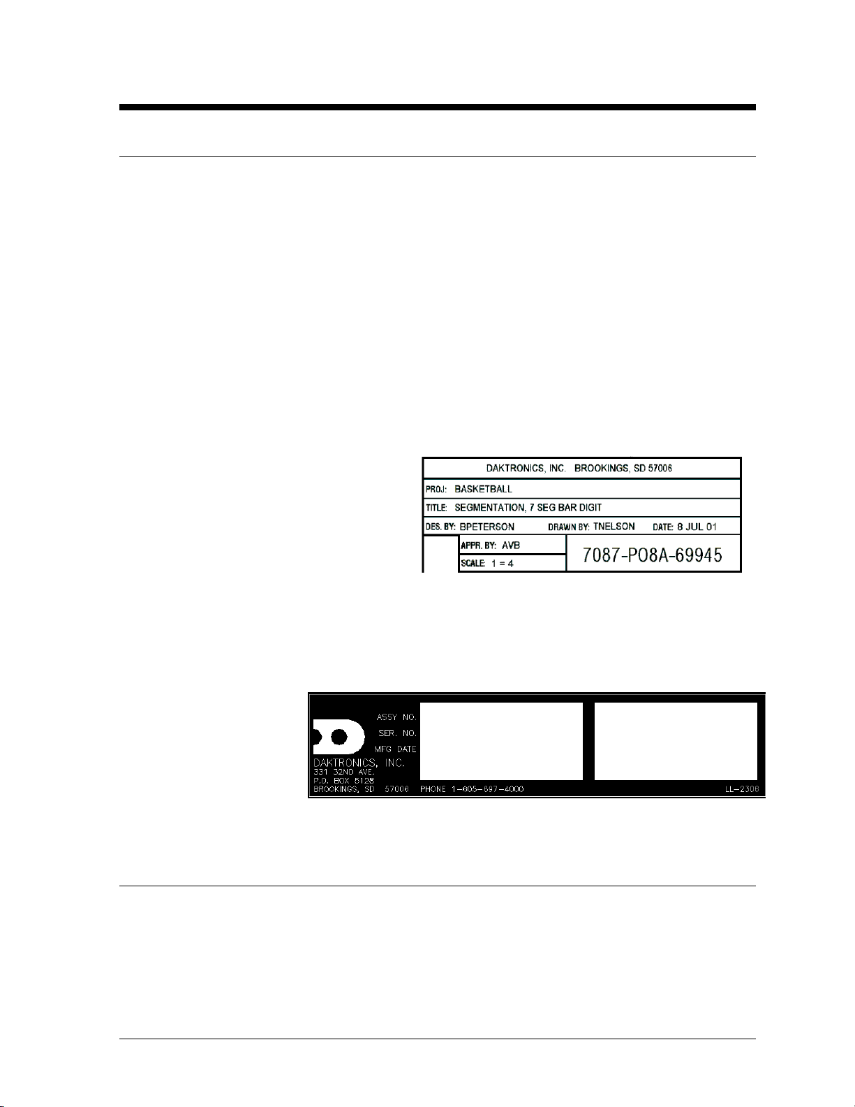
The box at right illustrates the Daktronics
drawing numbering system. Daktronics
identifies individual drawings by the drawing
number (7087-P08A-69945 in Figure 1),
which is located in the lower-right corner of
the drawing. This manual refers to drawings
by their last set of digits and the letter
preceding them. The example would be
Drawing A-69945.
Reference drawings are grouped and inserted in alphanumeric order in Appendix A.
The serial and model number of a Daktronics scoreboard can be found on the ID label, located on the
display. This label will be
similar to the one shown in
Figure 2. When calling
Daktronics Customer
Service, please have this
information available to
ensure that your request
is serviced as quickly
as possible.
Figure 2: Scoreboard ID Label
Figure 1: Daktronics Drawing Label
1 .2 Product Safety Approval
Daktronics outdoor scoreboards are ETL-listed, tested to CSA standards and CE-labeled for outdoor
use. Contact Daktronics with any questions regarding testing procedures.
Introduction
1-1
Page 6

1.3 Manual Overview
This manual is divided into the following sections:
Contains an overview of the manual and explains the Daktronics drawing
numbering system and Daktronics Exchange and Repair and Return
programs.
Contains tables showing all of the mechanical specifications, circuit
specifications, and maximum power requirements for each model.
Lists drawings needed to determine the location of scoreboard components.
Lists the electrical schematic drawings for each model.
Contains information needed for the mechanical installation for each model.
Contains information needed for the electrical installation for each model.
Contains information needed to service the scoreboards.
Contains information needed to service the team name message centers.
Contains descriptions and installation instructions for the various scoreboard
options.
Contain reference drawings and ED-7244, Eyebolts.
Section 10:
Appendices:
Section 1:
Section 2: Lists the drawings needed to determine scoreboard model numbers.
Section 3:
Section 4:
Section 5:
Section 6:
Section 7:
Section 8:
Section 9:
1.4 Daktronics Exchange and Repair and Return Programs
To serve customers’ repair and maintenance needs, Daktronics offers both an Exchange Program and a
Repair and Return Program.
Daktronics’ unique Exchange Program is a quick, economical service for replacing key components in
need of repair. If a component fails, Daktronics sends the customer a reconditioned replacement
within 24 hours. The customer, in turn, sends the failed component to Daktronics. This not only saves
money but also decreases scoreboard downtime. This service is provided to qualified customers who
follow the program guidelines explained below.
Daktronics provides this service to ensure users get the most from their Daktronics products. Please
call the Help Desk – (877) 605-1115 – if you have questions regarding the Exchange Program or any
other Daktronics service.
When you call the Daktronics Help Desk, a trained service technician will work with you to diagnose
the equipment problem and determine which replacement part to ship. (If, after you make the
exchange, the equipment still has problems, please contact our Help Desk immediately.) If the
replacement part fixes the problem, package the defective part in the same box and wrapping in which
the replacement part arrived, fill out and attach the enclosed UPS shipping document, and RETURN
THE PART TO DAKTRONICS.
For most equipment, you will be invoiced for the replacement part at the time it is shipped. This bill is
due when you receive it.
Daktronics expects immediate return of an exchange part if it does not solve the problem. The
company also reserves the right to refuse equipment that has been damaged due to acts of nature or
causes other than normal wear and tear.
1-2 Introduction
Page 7

If the defective equipment is not shipped to Daktronics within 30 working days from the invoice date,
it is assumed you are purchasing the replacement part, and you will be invoiced for it. This second
invoice represents the difference between the exchange price and the full purchase price of the
equipment. The balance is due when you receive the second invoice. If you return the exchange
equipment after 30 working days from the invoice date, you will be credited for the amount on the
second invoice, minus a restocking fee.
@To avoid a restocking charge, please return the defective equipment within 30 days from the
invoice date.
Daktronics also offers a repair and return program for items not subject to exchange.
Return Materials Authorization: To return parts for service, contact your local representative prior
to shipment to acquire a Return Materials Authorization (RMA) number. If you have no local
representative, call the Daktronics Help Desk for the RMA. This expedites repair of your component
when it arrives at Daktronics.
Packaging for Return: Package and pad the item well so that it will not be damaged in shipment.
Electronic components such as printed circuit boards should be installed in an enclosure or placed in
an antistatic bag before boxing. Please enclose your name, address, phone number and a clear
description of symptoms.
This is how to reach us:
Mail
Daktronics, Inc.
Phone
Fax
E-mail
: Customer Service
P.O. Box 5128
331 32nd Avenue
Brookings, SD 57006
: Daktronics Help Desk: 1 (877) 605-1115 (toll free)
or 1 (605) 697-4036
: 1 (605) 697-4444
: helpdesk@daktronics.com
Introduction
1-3
Page 8

Page 9

Section 2: Model Identification
Use the following drawings to determine your scoreboard model number. The drawings, located in the
Appendix, are inserted in alphanumeric order by drawing number.
Reference Drawings:
Single-Section Scoreboard Models....................................................... Drawing A-124342
Single-Section Scoreboard Models w/TNMC........................................Drawing A-127262
Single Section Scoreboard Models....................................................... Drawing A-152945
Model Identification
2-1
Page 10

Page 11

Section 3: Specifications
The following tables include all of the mechanical specifications, circuit specifications, and maximum
power requirements for each model in this manual. Models are listed in alphanumeric order.
Section 3.1: Single-Section Scoreboards ....................................................................................3-2
Section 3.2: 230-Volt Single-Section Scoreboards..................................................................... 3-5
Specifications
3-1
Page 12
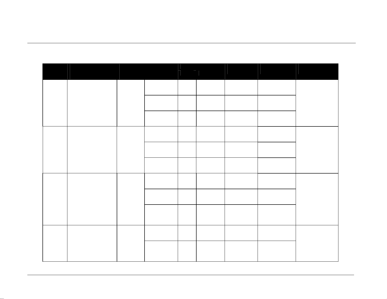
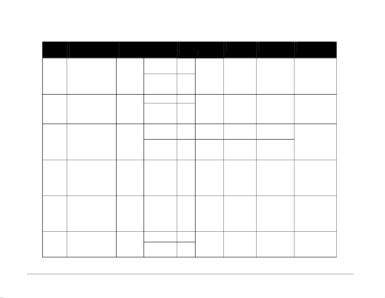
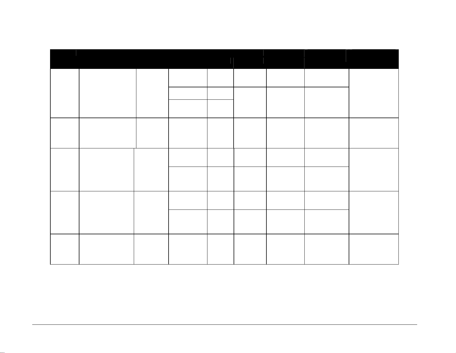
3.1 Single-Section Scoreboards
Note 1: Signal wires must be a minimum of 22- gauge with shield. Daktronics recommends using W-1234.
Note 2: 120/240 or two lines of 120 V AC from a 120/208 WYE service.
Wattage Model Dimensions
Lamp Maximum
25 W 1905 W
30 W 3280 W 120 V AC 27 A
40 W
25 W 1905 W 120 V AC
25 W 2780 W 120 V AC 24 A
40 W
25 W 2110 W 120 V AC
25 W 3035 W 120 V AC 26 A
40 W
25 W 3035 W 120 V AC 24 A
40 W
(See Note 2)
120 V AC
(Height, Width,
Depth)
BA-515 H3’-0", W6’-0", D11"
(914 mm, 1829 mm,
279 mm)
BA-518 H4’-0", W9’-0", D6"
(1219 mm, 2743 mm,
152 mm)
BA-618 H5’-0", W14’-0", D6"
(1524 mm, 4267 mm,
152 mm)
BA-624 H6’-0", W16’-0", D6"
(1829 mm, 4877 mm,
152 mm)
Weight
Uncrated
(Crated)
115 lb
52 kg
(118 lb)
(54 kg)
120 lb
55 kg
(152 lb)
(70 kg)
250 lb
114 kg
(580 lb)
(263 kg)
375 lb
170 kg
(770 lb)
(350 kg)
Digit Size
and Matrix
Inning, scores
15" 3x5
(381 mm)
Inning, scores
15" 4x7
(381 mm)
Ball, Strike,
Out indicators
Inning, scores
18" 3x5
(457 mm)
Inning, scores
18" 4x7
(457 mm)
Ball, Strike,
Out indicators
All digits
18" 3x5
(457 mm)
All digits
18" 4x7
(457 mm)
Ball, Strike,
Out, H/E
indicators
All digits
24" 4x7
(610 mm)
Ball, Strike,
Out, H/E
Indicators
Power
Amps per Line
(Single Phase)
16 A
16 A
18 A
Driver Number
and Address
A1 61
A1 61
A1 61
A1 61
Specifications 3-2
Page 13
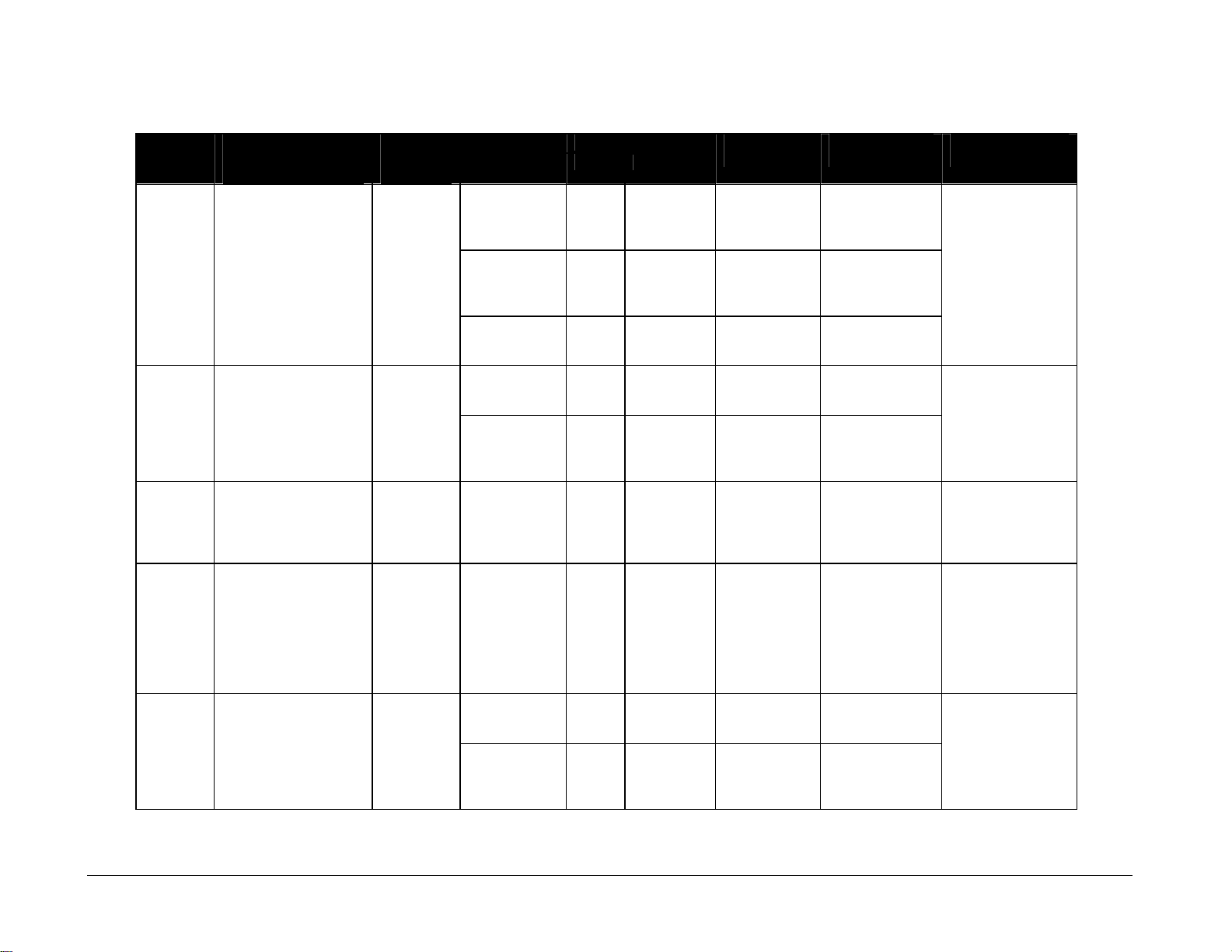
Wattage Model Dimensions
Lamp Maximum
25 W 2555 W 120 V AC
25 W 3780 W 120 V AC 32 A
40 W
25 W 3050 W 120/240 or
25 W 4675 W 120/240 or
40 W 1880 W 120/240 or
25 W 8491 W 120/240 or
25 W 975 W 120 V AC
25 W 1500 W 120 V AC
Power
(See Note 2)
120/208 V AC
120/208 V AC
120/208 V AC
120/208 V AC
Amps per Line
(Single Phase)
22 A
L1
15 A
L2 11 A
L1
23 A
L2 17 A
15 A A1 11
L1
33 A
L2 38 A
15 A
15 A
Driver Number
and Address
A1 62
A1 12
A1 67
A2 68
A3 69
A1 1
(Height, Width,
Depth)
BA-718 H4’-0", W12’-0", D6"
(1219 mm, 3658 mm,
152 mm)
BA-1018 H6’-0", W14’-0", D6"
(2438 mm, 4877 mm,
152 mm)
BA-2003 H4'-6", W10'-0", D8"
(1372 mm, 3048 mm,
203 mm)
BA-2004 H6'-6", W20'-0", D6"
(2845 mm, 6096 mm,
152 mm)
CT-2001 H2’-0", W6’-0", D11"
(610 mm, 1829 mm,
279 mm)
Weight
Uncrated
(Crated)
160 lb
73 kg
(490 lb)
(222 kg)
270 lb
122 kg
(621 lb)
(281 kg)
250 lb
113 kg
(475 lb)
(215 kg)
750 lb
340 kg
(1,425 lb)
(646 kg)
50 lb
23 kg
(83 lb)
(37 kg)
Digit Size
and Matrix
Inning, Time,
scores
18" 3x5
(457 mm)
Inning, Time,
scores
18" 4x7
(457 mm)
Ball, Strike,
Out indicators
All digits
18" 3x5
(457 mm)
All digits
18" 4x7
(457 mm)
All digits
36" 4x7
(914 mm)
Ball, strike,
out, H/E
18" 3x5
(457 mm)
Scoring
15" 3x5
(381 mm)
All digits
18" 3x5
(457 mm)
All digits
18" 4x7
(457 mm)
Specifications
3-3
Page 14

(Height, Width,
Depth)
CT-2002 H2’-7", W7’-0", D11"
(610 mm, 2133 mm,
279 mm)
FB-824 H4’-0", W14’-0", D6"
(1219 mm, 4267 mm,
152 mm)
FB-2340
MS-915 H4’-0", W8’-0", D11"
MS-918 H5’-0", W14’-0", D6"
H5'-0", W7'-0", D8"
(1524 mm, 2134 mm,
203 mm)
(1219 mm, 2438 mm,
279 mm)
(1524 mm, 4267 mm,
152 mm)
Weight
Uncrated
(Crated)
75 lb
34 kg
(125 lb)
(57 kg)
250 lb
114 kg
(560 lb)
(254 kg)
135 lb
61 kg
(220 lb)
(100 kg)
110 lb
50 kg
(185 lb)
(84 kg)
275 lb
125 kg
(640 lb)
(290 kg)
Digit Size
and Matrix
All digits
24" 4x7
(610 mm)
All digits
24" 4x7
(610 mm)
Quarter
indicators
All digits
18" 4x7
(457 mm)
All digits
15" 3x5
(381 mm)
Clock, scores
18" 3x5
(457 mm)
Inning
15" 3x5
(381 mm)
Clock, scores
18" 4x7
(457 mm)
Inning
15" 4x7
(381 mm)
Ball, Strike,
Out indicators
Wattage Model Dimensions
Lamp Maximum
25 W 1500 W 120 V AC
25 W
40 W
25 W 3000 W 120/240 or
25 W 2925 W 120/240 or
25 W 3285 W 120/240 or
25 W 4960 W 120/240 or
40 W
4160 W 120/240 or
Power
(See Note 2)
120/208 V AC
120/20 V AC
120/208 V AC
120/208 V AC
120/208 V AC
Amps per Line
(Single Phase)
15 A A1 1
L1
L2 17 A
L1 12.5 A
L2
12.5 A
L1
L2 14 A
L1
11 A
L2 17 A
L1
17 A
L2 24 A
Driver Number
and Address
18 A
A1 11
A1 2
11 A
A1 11
A1 11
Specifications 3-4
Page 15
Wattage Model Dimensions
Lamp Maximum
25 W
25 W
25 W
25 W 10 000 W 120/240 or
25 W 10 000 W 120/240 or
25 W 10 080 W 120/240 or
25 W 7206 W 120/240 or
25 W SO-824 H4’-0", W14’-0", D6"
40 W
4325 W 120/240 or
6245 W 120/240 or
4160 W 120/240 or
Power
(See Note 2)
120/208 V AC
120/208 V AC
120/208 V
AC
120/208 V AC
120/208 V AC
120/208 V AC
120/208 V AC
Amps per Line
(Single Phase)
L1
L2 20 A
L1
L2 28 A
L1
28 A
L2 28 A
L1
42 A
L2 42 A
L1
L2 28 A
L1
L2 28 A
L1
L2 17 A
Driver Number
and Address
17 A
A1 11
25 A
A1 11
A1 74
A2 75
25 A
A1 11
22 A
A1 11
18 A
A1 11
(Height, Width,
Depth)
MS-2002 H4’-6", W16’-0", D6"
(1372 mm, 4877 mm,
152 mm)
MS-2002
w/TNMC
MS-2004 H5’-0", W18’-0", D6"
MS-2006
w/TNMC
MS-2011
w/TNMC
H4’-6", W16’-0", D6"
(1372 mm, 4877 mm,
152 mm)
(1524 mm, 5486 mm,
152 mm)
H7'-0", W25'-0", D6"
(2134 mm, 7620 mm,
152 mm)
H4'-6", W20'-0", D6"
(1372 mm, 6096 mm,
152 mm)
(1219 mm, 4877 mm,
152 mm)
Weight
Uncrated
(Crated)
250 lb
114 kg
(715 lb)
(324 kg)
425 lb
193 kg
(740 lb)
(336 kg)
375 lb
170 kg
(770 lb)
(350 kg)
500 lb
227 kg
(850 lb)
(386 kg)
475 lb
215 kg
(903 lb)
(410 kg)
250 lb
114 kg
(560 lb)
(254 kg)
Digit Size
and Matrix
Clock, scores
24" 4x7
(610 mm)
Period
18" 3x5
(457 mm)
Period
18" 3x5
(457 mm)
All digits
18" 3x5
(457 mm)
All digits
18" 4x7
(457 mm)
Clock, scores
30" 4x7
(762 mm)
Period
24" 4x7
(610 mm)
Clock, scores
24" 4x7
(610 mm)
Period
15" 3x5
(381 mm)
24" 4x7
(610 mm)
Half
indicators
Specifications
3-5
Page 16
Weight
(Height, Width,
Depth)
SO-918 H4’-0", W12’-0", D6"
(1219 mm, 3658 mm,
152 mm)
SO-2008
w/TNMC
TI-218 H2’-0", W3’-0", D11"
TI-418 H2’-0", W6’-0", D11"
TI-2003 H3’-0", W4’-0", D11"
H5'-6", W16'-0", D6"
(1676 mm, 4877 mm,
152 mm)
(610 mm, 914 mm,
279 mm)
(787 mm, 1829 mm,
279 mm)
(914 mm, 1219 mm,
279 mm)
Uncrated
(Crated)
225 lb
102 kg
(455 lb)
(206 kg)
300 lb
136 kg
(570 lb)
(259 kg)
20 lb
9 kg
(57 lb)
(26 kg)
50 lb
23 kg
(87 lb)
(40 kg)
110 lb
50 kg
(150 lb)
(68 kg)
Digit Size
and Matrix
18" 3x5
(457 mm)
18" 4x7
(457 mm)
Half
Indicators
All digits
18" 3x5
(457 mm)
All digits
18" 3x5
(457 mm)
All digits
18" 4x7
(457 mm)
All digits
18" 3x5
(457 mm)
All digits
18" 4x7
(457 mm)
All digits
30" 4x7
(762 mm)
Wattage Power Model Dimensions
Lamp Maximum (See Note 2)
25 W 2925 W 120/240 or
120/208 V
AC
25 W
40 W
25 W 6145 W 120/240 or
25 W
25 W 1000 W 120 V AC 9
25 W
25 W 2000 W 120 V AC 17
40 W 1600 W 120 V AC 14 A1 2
4500 W 120/240 or
120/208 V
AC
120/208 V
AC
650 W
1300 W
120 V AC
120 V AC
Amps per Line
(Single Phase)
L1
11 A
L2 17 A
L1
17 A
L2 21 A
L1
L2 30 A
6
11
Driver Number
and Address
A1 11
22 A
A1 17
A1 2
A1 1
Specifications 3-6
Page 17
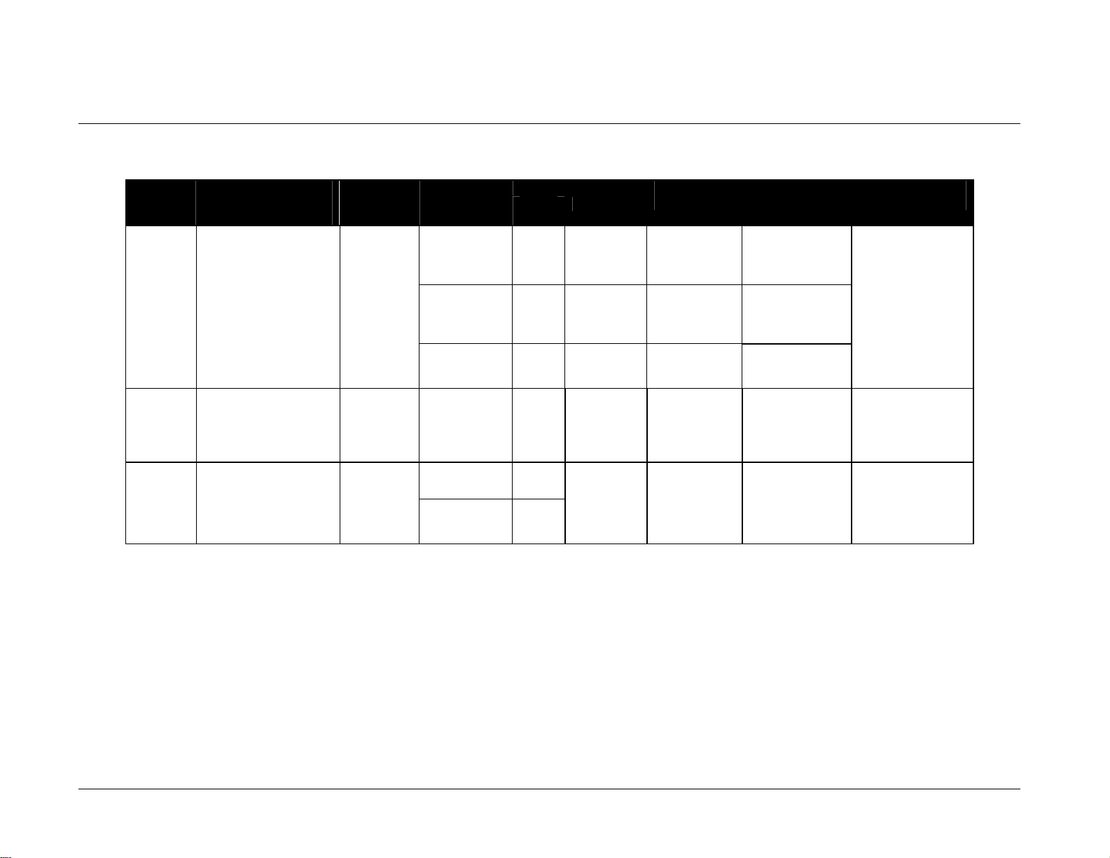
3.2 230 Volt Single-Section Scoreboards
Note 1: Signal wires must be a minimum of 22-gauge with shield. Daktronics recommends using W-1234.
BA-518 H4’-0", W9’-0", D6"
CT-2001 H2’-0", W6’-0", D11"
(Height, Width,
Depth)
(1219 mm, 2743 mm,
152 mm)
(610 mm, 1829 mm,
279 mm)
(1219 mm, 4877 mm,
152 mm)
Weight
Uncrated
(Crated)
120 lb
55 kg
(152 lb)
(70 kg)
50 lb
23 kg
(83 lb)
(37 kg)
250 lb
114 kg
(560 lb)
(254 kg)
Digit Size
and Matrix
Inning,
scores
18" 3x5
(457 mm)
Inning,
scores
18" 4x7
(457 mm)
Ball, Strike
Out indicators
All digits
18" 4x7
(457 mm)
24" 4x7
(610 mm)
Half
indicators
Wattage Model Dimensions
Lamp Maximum
25 W 1905 W
25 W 2780 W 230 V AC 12 A
40 W
30 W 1800 W 230 V AC
25 W SO-824 H4’-0", W14’-0", D6"
40 W
4160 W 230 V AC L1 9 A
230 V AC
Power
Amps per Line
(Single Phase)
8 A
8 A A1 1
L2
9 A
Driver Number
and Address
A1 61
A1 11
Specifications
3-7
Page 18

Page 19
Section 4: Component Locations
Use the following drawings to determine the location of scoreboard components. The drawings are
listed below in alphanumeric order by model number. In the Appendix, they are inserted in
alphanumeric order by drawing number.
Model Drawing Name Drawing No.
BA-515 Component Locations, BA-515 A-126083
BA-518 Component Locations, BA-518 A-126084
BA-618 Component Locations, BA-618 A-126221
BA-624 Component Locations, BA-624 A-126285
BA-718 Component Locations, BA-718 A-126306
BA-1018 Component Locations, BA-1018 A-126353
BA-2003 Component Locations, BA-2003 A-158315
BA-2004 Component Locations, BA-2004 A-152733
CT-2001 Component Locations, CT-2001 A-126429
CT-2002 Component Locations, CT-2002 A-126430
FB-824 Component Locations, FB-824 A-126431
FB-2340 Component Locations, FB-2340 A-137679
MS-915 Component Locations, MS-915 A-126432
MS-918 Component Locations, MS-918 A-124343
MS-2002 Component Locations, MS-2002 A-127235
MS-2002 w/TNMC Component Locations, MS-2002 w/TNMC A-127193
MS-2002 w/TNMC
and 40W Lamps
MS-2004 Component Locations, MS-2004 A-128047
MS-2006 w/TNMC Component Locations, MS-2006 w/TNMC A-132960
MS-2011 w/TNMC Component Locations; MS-2011 A-138889
SO-824 Component Locations, S0-824 A-127285
SO-918 Component Locations, S0-918 A-126433
SO-2008 w/TNMC Component Locations; SO-2008 w/ 832-12 w/TNMC A-150127
TI-218 Component Locations, TI-218 A-126364
TI-418 Component Locations, TI-418 A-126372
TI-2003 Component Locations, TI-2003 A-126434
Component Locations, MS-2002 w/TNMC
and 40W Lamps
A-135738
Component Locations
4-1
Page 20

Page 21
Section 5: Schematics
Use the following table to determine the schematic for your scoreboard model. The drawings are listed
below in alphanumeric order by model number. In the Appendix, they are and inserted in
alphanumeric order by drawing number.
Model Schematic Name Drawing No.
BA-515 Schematic, 1 Driver 8 Column A-124298
BA-518 Schematic, 1 Driver 8 Column A-124298
BA-518, 230 V AC Schematic, 1 Driver 16 Col. Overseas A-139639
BA-618 Schematic, 1 Driver 8 Column A-124298
BA-624 Schematic, 1 Driver 8 Column A-124298
BA-718 Schematic, 1 Driver 8 Column A-124298
BA-1018 Schematic, 1 Driver A-124293
BA-2003 Schematic, 1 Driver 8 Column A-124298
BA-2004 Schematic; BA-2004 B-155111
CT-2001 Schematic, 1 Driver 8 Column A-124298
CT-2001, 230 V AC Schematic, 1 Driver 8 Col. Overseas A-139733
CT-2002 Schematic, 1 Driver 8 Column A-124298
FB-824 Schematic, 1 Driver A-124293
FB-2340 Schematic, 1 Driver A-124293
MS-915 Schematic, 1 Driver A-124293
MS-915, 230 V AC Schematic, 1 Driver 16 Col. Overseas A-139639
MS-918 Schematic, 1 Driver A-124293
MS-2002 Schematic, 1 Driver A-124293
MS-2002 w/TNMC Schematic; 1 Drvr with 32 or 48-10 TNMC B-127394
MS-2002 w/TNMC and
40W Lamps
MS-2004 Schematic, 2 Drivers A-124291
MS-2006 w/TNMC Schematic, 2 Drivers w/32 or 48-12 TNMC B-132144
MS-2011 w/TNMC Schematic; 1 Drvr with 32 or 48-10 TNMC A-127394
SO-824 Schematic, 1 Driver A-124293
SO-824, 230 V AC Schematic, 1 Driver 16 Col. Overseas A-139639
SO-918 Schematic, 1 Driver A-124293
SO-2008 w/TNMC Schematic; 1 Drvr with 32 or 48-10 TNMC A-127394
TI-218 Schematic, 1 Driver 8 Column A-124298
TI-418 Schematic, 1 Driver 8 Column A-124298
TI-2003 Schematic, 1 Driver 8 Column A-124298
TNMC, 832-12 Schematic, 832-12 TNMC A-125214
TNMC, 848-12 Schematic, 848-12 TNMC A-125216
Schematic, 2 Drivers w/32 or 48-12 TNMC B-132144
Schematics
5-1
Page 22

Page 23

Section 6: Mechanical Installation
Mechanical installation consists of installing concrete footings and steel beams, and mounting the
scoreboard and accompanying ad panels to the beams.
6.1 Footings and Beams
Reference Drawings:
Installation Specifications; BA 515.......................................................... Drawing A-55003
Installation Specifications; BA 518.......................................................... Drawing A-55004
Installation Specifications; BA 618.......................................................... Drawing A-55006
Installation Specifications; BA 624.......................................................... Drawing A-55007
Installation Specifications; BA 718.......................................................... Drawing A-55005
Installation Specifications; BA 1018........................................................ Drawing A-61904
Installation Specifications; BA-2003...................................................... Drawing A-158322
Installation Specifications; BA-2004 & BA-2005 ................................... Drawing A-152777
Installation Specifications; FB-2340............................................................ Drawing A-169388
Installation Specifications; MS 824 ....................................................... Drawing A-127287
Installation Specifications; MS-915 .......................................................Drawing A-113568
Installation Specifications; MS 918 ......................................................... Drawing A-55009
Installation Specifications; MS-2002 .....................................................Drawing A-127195
Installation Specifications; MS 2002 w/TNMC ......................................Drawing A-127195
Installation Specifications; MS-2004 .....................................................Drawing A-128788
Installation Specifications; MS-2006 w/TNMC ......................................Drawing A-135575
Installation Specifications; MS-2011 w/TNMC ......................................Drawing A-135414
Installation Specifications; SO 824........................................................Drawing A-127287
Installation Specifications; SO 918..........................................................Drawing A-55010
Installation; TI-2003............................................................................... Drawing A-139316
Installation Specifications; SO-2008 ..................................................... Drawing A-149074
Installation Specifications; TI-2003 ....................................................... Drawing A-169367
Installation Specifications; TI-218 ......................................................... Drawing A-169376
Installation Specifications; TI-418 ......................................................... Drawing A-169380
Refer to the installation specification drawings listed above for the rear view of each of the models.
These drawings specify the number of beams and the recommended spacing between them. It is
critical that these dimensions be adhered to for scoreboards with team name message centers because
of the ventilation hoods located on the rear of the displays.
These drawings also indicate the size of beams required to support the scoreboard at different heights
under various wind speed conditions. All of the beam specifications illustrate "W" shape steel beams
(wide-flange I-beams). The first number indicates the front-to-rear depth of the beam, and the second
number indicates the weight in pounds per foot of length.
The column and footing size dimensions provided in the drawings assist with estimating installation
costs. They are estimates only and are not intended for construction purposes. Be sure that your
installation complies with local building codes and is suitable for your particular soil and wind
conditions.
Mechanical Installation
6-1
Page 24
The columns and footings and all connection details must be designed and certified by a professional
engineer licensed to practice in the state in which scoreboard will be installed. Daktronics does not
assume any liability for any installation derived from the information and drawings provided in this
manual or designed and installed by others.
6.2 Lifting the Scoreboard
Reference Drawings:
Lifting Scoreboard ................................................................................... Drawing A-44548
Lifting Small Baseball Scoreboard ..........................................................Drawing A-58668
Small Daktronics scoreboards are not equipped with eyebolts. Refer to Drawing A-58668 for lifting
details.
Larger scoreboard sections and message centers are shipped equipped with eyebolts that are used to
lift the displays. The eyebolts are located along the top of the cabinet for each scoreboard or
scoreboard section.
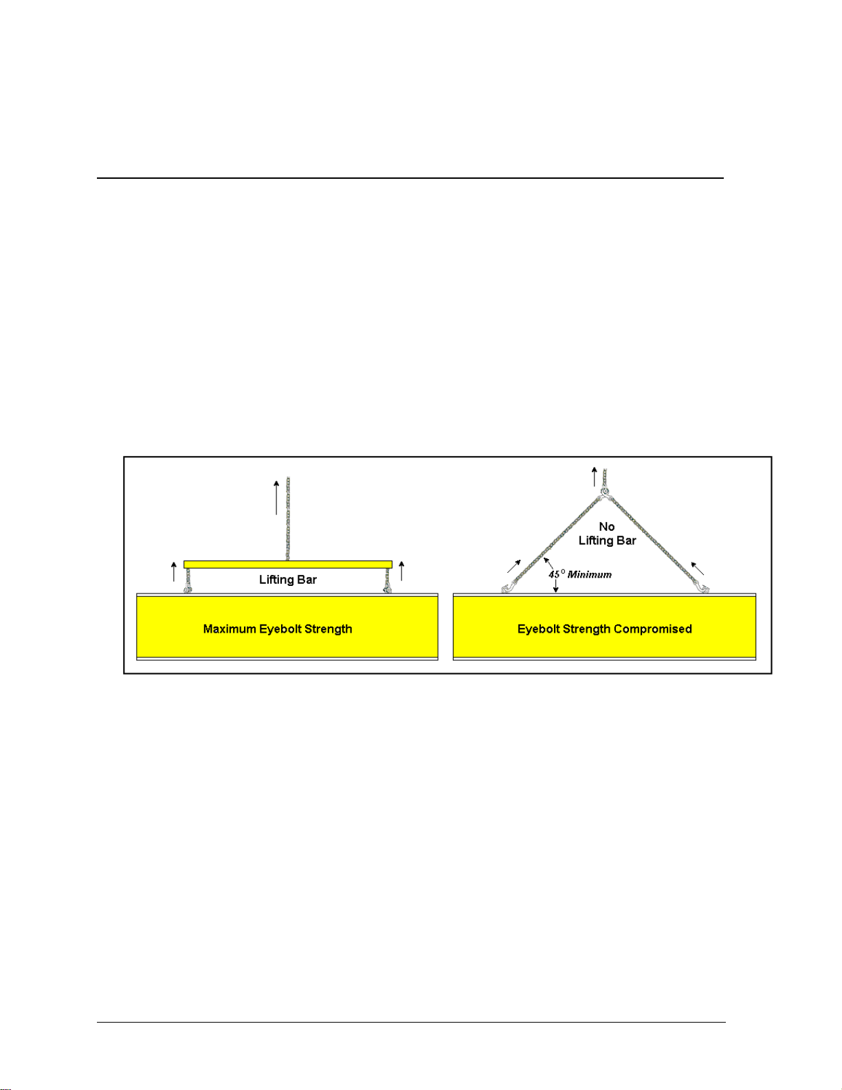
Daktronics strongly recommends using a spreader bar, or lifting bar, to lift the display. Using a
spreader bar ensures that the force on the eyebolts is straight up, minimizing lifting stress. Lifting
methods are shown in the illustration below and in Drawing A-44548.
Figure 3: Lifting the Display
Figure 3 above illustrates both the preferred method (left example) and an alternative method (right
example) for lifting a scoreboard. When lifting the display:
Use a spreader bar.
Use every lifting point provided.
Take special care to ensure the rated load of the eyebolts is not exceeded. Refer to ED-7244,
Eyebolts, to determine allowable loads and load angles for the lifting hardware. ED-7244 is located in
the Appendix of this manual.
Avoid using other lifting methods. Cables and chains attached to the eyebolts and directly to a center
lifting point, as show in the right-hand example in Figure 3, can create a dangerous lateral force on
the eyebolts and may cause the eyebolts to fail. Daktronics scoreboards use
eyebolts mounted to a
1
/8" aluminum plate or steel nut plate, but exceeding load angles or weight
limits could cause the bolts to pull out or the scoreboard cabinet to buckle. In either circumstance, the
result
1
/2" and 5/8" shoulder-type
6-2
Mechanical Installation
Page 25
would be serious damage to the scoreboard. If you must use this method, ensure a minimum angle
between the chain and scoreboard of at least 45°.
KNote: Daktronics assumes no liability for scoreboard damage resulting from incorrect
setup or incorrect lifting methods.
Eyebolts are intended for lifting only. Do not attempt to permanently support the display by the
eyebolts.
In typical multi-section installations, the lower scoreboard section is installed first and secured to the
support beams, and then the upper section is placed atop or above the lower section and attached to the
beams. There may be cables extending from the top of the lower section. Guide these cables into the
hole in the bottom of the upper section for later connection.
If the lift eyebolts are removed, plug the holes with bolts and the rubber sealing washers that were
removed with the eyebolts. Apply silicone or another waterproof sealant to the eyebolt openings.
Inspect the top and sides of the display for any other holes or openings that may allow moisture to
enter the display, and plug and seal those openings as well.
6.3 Scoreboard Mounting
Use the following table to determine the mounting method for your scoreboard.
Method 1
Method 2
BA-618, BA-624, BA-918, BA-1018, BA-2003, BA-2004, FB-824, MS-918, SO824, SO-918, SO-2008, MS-2002, MS-2004, MS-2011
BA-515, BA-518, BA-718, CT-2001, CT-2002, FB-2340, MS-915, TI-218, TI418, TI-2003, MS-2006
Method 1
Reference Drawings:
Display Mounting......................................................................... Drawing A-44412
Ad Panel Mounting...................................................................... Drawing A-52187
Installation Specifications, BA 618 ..............................................Drawing A-55006
Installation Specifications, BA 624 ..............................................Drawing A-55007
Installation Specifications, BA-2003.......................................... Drawing A-158322
Installation Specifications; BA-2004 & BA-2005........................ Drawing A-152777
Installation Specifications, FB-824/SO-824............................... Drawing A-127287
Installation Specifications, MS 918.............................................. Drawing A-55009
Installation Specifications, SO 918.............................................. Drawing A-55010
Installation Specifications, BA 1018 ............................................Drawing A-61904
Installation Specifications, MS-2002 ......................................... Drawing A-127195
Installation Specifications, MS-2004 ......................................... Drawing A-128788
Installation Specifications, SO-2008.......................................... Drawing A-149074
Installation Specifications; MS-2011 w/TNMC ..........................Drawing A-135414
Drawing A-44412 shows the hardware used for mounting the scoreboard to the beams. Each
section of the scoreboard attaches at the top and the bottom to all the beams. Drawing A-44412
also shows top and side views of the scoreboard secured to the beams. Note that the threaded rods
do not pass through the flanges of the beams, but instead run along both sides of each beam. Refer
Mechanical Installation
6-3
Page 26

to the Installation Specifications drawing for your model to determine the center-to-center
distance of the poles.
Review the illustrations of the mounting hardware in Drawing A-44412, and then use the
following procedure for each section.
1. Loosely attach the inner and outer mounting clamps to the rear flanges of the
scoreboard’s horizontal frame members, using the
and position the clamps to fit on either side of the beams.
2. Insert a
1
/2" square nut into each mounting clamp. From the rear, screw a threaded rod
3
/8" bolts. Measure the beam spacing,
into each of the nuts.
3. Position the scoreboard at the front of the beams with the threaded rods extending from
the rear of the clamps, straddling the beams. Raise the scoreboard section to the desired
height.
4. Slide clamping angles over the ends of the rods and loosely install the washers and nuts.
5. Make final adjustments in the positioning of the scoreboard. Tighten the
3
/8" bolts in the
mounting clamps.
6. Make sure that the threaded rods are perpendicular to the scoreboard, and tighten all of
the
1
/2" nuts.
Method 2
Reference Drawings:
Scoreboard Mounting ..................................................................Drawing A-55101
Installation Specifications, BA 515 ..............................................Drawing A-55003
Installation Specifications, BA 518.............................................. Drawing A-55004
Installation Specifications, BA 718.............................................. Drawing A-55005
Installation Specifications, FB-2340 .......................................... Drawing A-169388
Installation Specifications, MS-915 ........................................... Drawing A-113568
Installation Specifications, MS-2006 ......................................... Drawing A-135575
Installation Specifications; TI-2003............................................ Drawing A-169367
Installation Specifications; TI-218.............................................. Drawing A-169376
Installation Specifications; TI-418.............................................. Drawing A-169380
Refer to Drawing A-55101 for mounting details. Refer to the Installation Specifications drawing
for your model to determine the center-to-center distance of the poles.
Mount the scoreboard as follows:
1. Use the mounting channel to determine which hole combination to use. Be sure to keep
the bolts as close to the beam as possible.
2. Using the mounting channel as a template, drill
flange of the scoreboard where the supports will go.
3. Place square nuts inside the channel and thread the bolts through.
4. Lift the scoreboard into position with the bolts still in place.
5. Place mounting angles over each pair of bolts and secure with lockwashers and hex nuts.
6. After adjusting the scoreboard to the final desired position, tighten hex nuts firmly.
When mounting a scoreboard with back sheets, remove the back sheets in the areas above and
below the holes drilled in the upper and lower rear flange of the scoreboard. Be sure to replace the
back sheets after placing the square nuts inside the channel and threading the bolts through the
holes.
9
/16" holes in the upper and lower rear
6-4
Mechanical Installation
Page 27

6.4 Ad Panel Mounting
Reference Drawings:
Ad Panel Mounting.................................................................................. Drawing A-52187
Assembly, Ad Panel, BA-515.................................................................. Drawing A-52585
Ad Panel Mounting, BA-518.................................................................... Drawing A-52811
Refer to Drawing A-52187 for mounting details.
Mount the ad panel(s) as follows:
1. Use the mounting channel to determine which hole combination to use. Be sure to keep the
bolts as close to the beam as possible.
2. Using the mounting channel as a template, drill
of the ad panel where the supports will go.
3. Place square nuts inside the channel and thread the bolts through.
4. Lift the ad panel into position with the bolts still in place.
5. Place mounting angles over each pair of bolts and secure with lock washers and hex nuts.
6. When the panel is adjusted to the final desired position, tighten hex nuts firmly.
When mounting ad panels with back sheets, remove the back sheets in the areas above and below
the holes drilled in the upper and lower rear flange of the ad panel. Be sure to replace the back
sheets after placing the square nuts inside the channel and threading the bolts through the holes.
9
/16" holes in the upper and lower rear flange
Models BA-515 and BA-518
Ad panels are mounted directly to the scoreboard for models BA-515 and BA-518. Refer to
Drawings A-52585 and A-52811 for mounting details.
Mechanical Installation
6-5
Page 28

Page 29

Section 7: Electrical Installation
Reference Drawings:
Components 8/16 Pos Power and Signal Entrance.............................. Drawing A-109114
Components 2/4 Pos Power and Signal Entrance................................ Drawing A-125977
Electrical installation consists of:
Providing power and ground to a disconnect near the scoreboard.
Routing power and ground from the main disconnect to the scoreboard power and signal
entrance enclosure.
Connecting the scoreboard ground to a grounding electrode at the scoreboard location.
Routing the control signal cable from the control location to the scoreboard location.
Connecting several cables from the lower to the upper section.
Route power and signal cables into the scoreboard from the rear. There are two knockouts for conduit
connection in the back. All wires connect to the entrance plate. Drawings A-109114 and A-125977
illustrate the two types of entrance panels.
7.1 Power Requirements
Reference Drawings:
Components 8/16 Pos Power and Signal Entrance.............................. Drawing A-109114
Components 2/4 Pos Power and Signal Entrance................................ Drawing A-125977
Refer to the chart in Section 3 to determine circuit specifications and maximum power requirements
for the models described in this manual.
Daktronics outdoor scoreboards have been designed for easy access to components, and the power and
control signal hookup has been simplified. Front panels are removable to allow access to the digits,
cabling and other electronic components.
Proper power installation is imperative for proper display operation. The following subsections give
details of display power installation.
Grounding
Displays MUST be grounded according to the provisions outlined in Article 250 of the
National Electrical Code
The display system must be connected to earth-ground. Proper grounding is necessary for reliable
equipment operation. It also protects the equipment from damaging electrical disturbances and
lightning. The display must be properly grounded or the warranty will be void.
The material of an earth-ground electrode differs from region to region and from conditions
present at the site. Consult the National Electrical Code and any local electrical codes that may
apply. The support structure of the display cannot be used as an earth-ground electrode. The
support is generally embedded in concrete, and if in earth, the steel is either primed or it corrodes,
making it a poor ground.
Electrical Installation
®
. Daktronics recommends a resistance to ground of 10 ohms or less.
7-1
Page 30
Power Installation
There are two basic considerations for power installation: installation with ground and neutral
conductors provided, and installation with only a neutral conductor provided. These two power
installations differ slightly, as described in the following paragraphs:
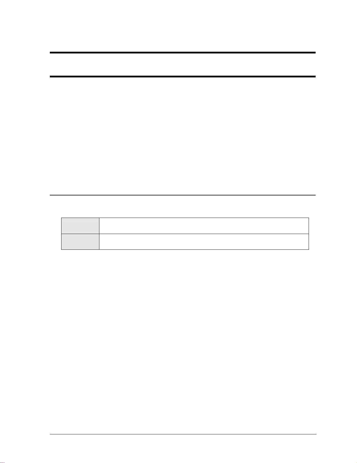
Installation with Ground and Neutral Conductors Provided
For this type of installation, the power cable must contain an isolated earth-ground conductor.
In this circumstance, do not connect neutral to ground at the disconnect or at the display. This
would violate
electrical codes
and void the
warranty. Use a
disconnect so that
all hot lines and
neutral can be
disconnected. The
National Electrical
Code requires the
use of a lockable
power disconnect
within sight of or
at the display.
Figure 4: Installation with Ground and Neutral Conductor Provided
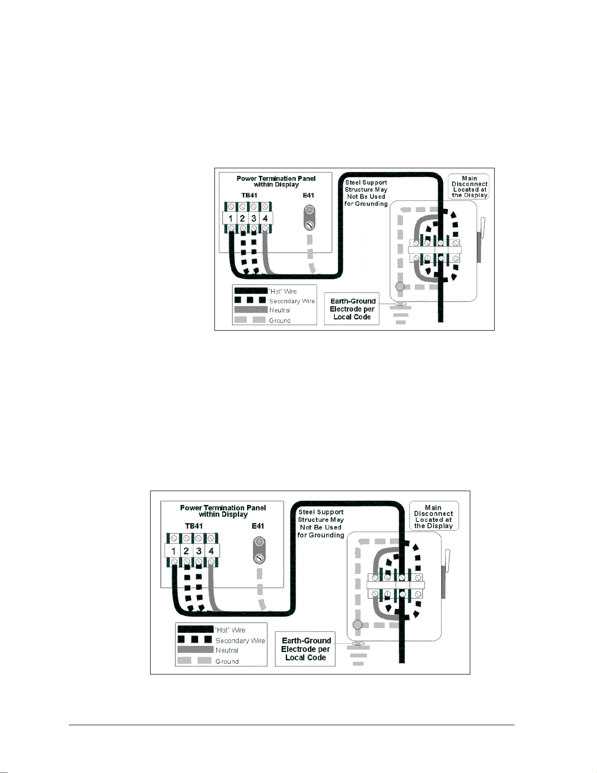
Installation with Only a Neutral Conductor Provided
Installations where no grounding conductor is provided must comply with Article 250-32 of
the National Electrical Code. If the installation in question meets all of the requirements of
Article 250-32, the following guidelines must be observed:
Connect the grounding electrode cable at the local disconnect, never at the display
entrance enclosure.
Use a disconnect that opens all of the ungrounded phase conductors.
Bond the neutral and the ground conductors in the display power entrance enclosure.
Figure 5: Installation with Only Neutral Conductor Provided
7-2
Electrical Installation
Page 31

The scoreboard must be connected to earth ground. Proper grounding is necessary for reliable
equipment operation. It also serves to provide protection to the equipment against damaging electrical
disturbances and lightning. Failure to adhere to the following grounding methods will void the
warranty.
The steel support structure for the scoreboard cannot be used as grounding. The support is generally
embedded in concrete, and if in earth, the steel is either primed or it corrodes, making it a poor ground.
Use one ground electrode (typically, a ground rod) at each scoreboard support column.
The power cable must contain a separate earth-ground conductor. When a separate ground conductor
is used, do not connect neutral to ground at the disconnect or at the scoreboard. To do so would violate
electrical codes and void the warranty. Refer to Figure 5.
The National Electrical Code requires the use of a lockable power disconnect near the scoreboard. The
customer must provide a lockable disconnect switch (knife switch) at the scoreboard location so that
all power lines can be completely disconnected. Use a multi-conductor disconnect so that all hot lines
and the neutral can all be disconnected. This is important in protecting the scoreboard against
lightning.
K Note: Do not connect ground to neutral at the scoreboard. Doing so voids the warranty and may
violate electrical codes.
7.2 Power and Signal Connection
Reference Drawings:
Components 8/16 Pos Power and Signal Entrance.............................. Drawing A-109114
Components 2/4 Pos Power and Signal Entrance................................ Drawing A-125977
To gain access to the entrance panel, open the access door and remove the cover from the entrance
enclosure. Refer to Section 4: Component Locations for the location of the access door for the model
of your scoreboard.
Connect the power and signal cables to the entrance panel as shown in Drawings A-109114 and A-
125977.
Electrical Installation
7-3
Page 32

Page 33

Section 8: Digit Maintenance
and Troubleshooting
IMPORTANT NOTES:
1. Disconnect power before doing any repair or maintenance work on
the scoreboard!
2. Allow only qualified service personnel access to internal display
electronics.
3. Disconnect power when not using the scoreboard.
For assistance in the maintenance of the optional message center, refer to
the manual that accompanies the message center or to Section 9 in this
manual.
8.1 Component Access
Lamp Driver Access
Refer to the Component Locations drawings listed in Section 4 for the location of the lamp
drivers. To access a lamp driver:
1. Open the access panel by turning the
2. Remove the driver enclosure cover.
3. Disconnect the plugs.
4. Remove the wing nuts securing the lamp driver to the enclosure.
5. Carefully pull out the lamp driver and set it on a clean, flat surface.
Important: When the lamp drivers are replaced, plugs P25 and P26 (if present) must be
removed from the old driver and plugged into the new driver.
1
/4-turn screws. The door will swing open.
Digit Access
Reference Drawing:
Digit Service ................................................................................ Drawing A-27674
Use the following instructions to remove a digit from the front of the scoreboard.
Note: The digit does not need to be removed to change the lamps.
1. Remove the screws securing the screen (refer to Drawing A-27674).
2. Carefully pull the digit out part way so that the ground wire can be unscrewed and the
harness unplugged.
3. Place the digit on a clean level surface.
Digit Maintenance and Troubleshooting
8-1
Page 34

8.2 Lamp Replacement
Reference Drawing:
Digit Service ............................................................................................Drawing A-27674
The primary service required for Daktronics baseball scoreboards is to periodically replace bad lamps.
Refer to the table in Section 3 to determine the wattage of the lamps the scoreboard uses. Refer to
Section 8.8 to determine the part numbers. Do not use higher-wattage lamps or damage to the circuit
may result. Refer to Drawing A-27674 to access a digit.
8.3 Lamp Drivers
Reference Drawings:
Layout, 16 Column Driver III ................................................................. Drawing A-123940
Layout, 8 Column Driver III ................................................................... Drawing A-123941
Important: When the lamp drivers are replaced, plugs P25 and P26 (if present) must be removed
from the old driver and plugged into the new driver.
In the scoreboard, the lamp drivers perform the task of switching digit lamps on and off (refer to
Drawings A-123940 and A-123941).
Each lamp driver has connectors providing power and signal inputs to the circuit, and outputs to the
digits and indicators. The connectors function as follows:
8-Column Lamp Driver
Connector No. Function
1 – 8 Outputs to digits and indicators
17 Control signal input
18 Power input for outputs 1 – 8
19 Power input (120V) for driver
16-Column Lamp Driver
Connector No. Function
1 – 16 Outputs to digits and indicators
17 Control signal input
18 Power input for outputs 1 – 8
19 Power input (120V) for driver
20 Power input for outputs 9 - 16
Output connectors to the digits and indicators each have nine pins. Pin 7 provides power (hot) to the
digit or indicators wired to that connector. The other eight pins provide switching connections.
8-2
Digit Maintenance
and Troubleshooting
Page 35

8.4 Fuses
Reference Drawings:
Layout, 16 Column Driver III .................................................................Drawing A-123940
Layout, 8 Column Driver III ...................................................................Drawing A-123941
The digit lamp driver has 17 fuses. There is one fuse to protect each digit circuit. F1 through F16 are
located near each output connector under the driver’s metal cover. The lamp driver’s other fuse, F17
protects the driver’s logic circuit and fan. Refer to Drawings A-123940 and A-123941for an
illustration of the driver and these fuses. Refer to Section 8.8 to determine the part numbers for
replacement fuses.
8.5 Segmentation
Reference Drawing:
Digit Segments, 3x5 and 4x7 ..................................................................Drawing A-46653
In each digit, certain lamps always go on and off together. These groupings of lamps are referred to as
segments. Drawing A-46653 shows the segmentation of 3x5 and 4x7digits, which connector pin is
wired to each digit segment and the wiring color code used in all driver-to-lamp connections.
8.6 Power On Self-Test
Reference Drawings:
Incandescent Driver Power Up Self-Test.............................................. Drawing A-128283
Power Up Self Test on a FB-1424 ........................................................Drawing A-128301
The scoreboard performs a self-test each time that power is turned on and the control console is
powered off or not attached to the scoreboard. If the control console is attached and powered on, the
self-test does not run and data from the control console is displayed on the scoreboard after a brief
period of time.
The self-test runs in three cycles or phases. The pattern of the self-test varies depending on the
scoreboard model, number of drivers, and type of digits.
Drawing A-128283 shows how the test pattern displays in the digits when the address (P25)
and protocol (P26) plugs are not plugged into the lamp drivers.
Drawing A-128302 shows the test pattern displayed on a scoreboard that has one lamp driver
with the address (P25) plugged in.
These are the three cycles of the self-test:
Cycle 1:
Displays the protocol in digits that are controlled by lamp driver A1. P0 is always
displayed when P26 is not installed.
Cycle 2:
Cycle 3:
Digit Maintenance
and Troubleshooting
Displays the driver number and address in the digits that are controlled by each
driver. A000 is always displayed when P25 is not installed.
Displays a rotating pattern in all digits. The pattern starts in row 1 and rotates
through row 8 (refer to Drawing A-128283).
8-3
Page 36

8.7 Lightning Protection
The Transient Voltage Surge Suppresser (TVSS), located in the load center, reduces the brief surge
induced into the power lines when lightning strikes in the vicinity of the scoreboard. A varistor in the
power lines to the driver logic also helps to protect this circuit by reducing such surges.
The use of a disconnect near the scoreboard to completely cut all current-carrying lines significantly
protects the circuits against lightning damage. The National Electrical Code also requires it. In order
for this to provide protection, the power must be disconnected when the scoreboard is not in use. The
control console should also be disconnected from power and from the signal J-box when the system is
not in use. The same surges that may damage the scoreboard’s driver can also damage the console’s
circuit.
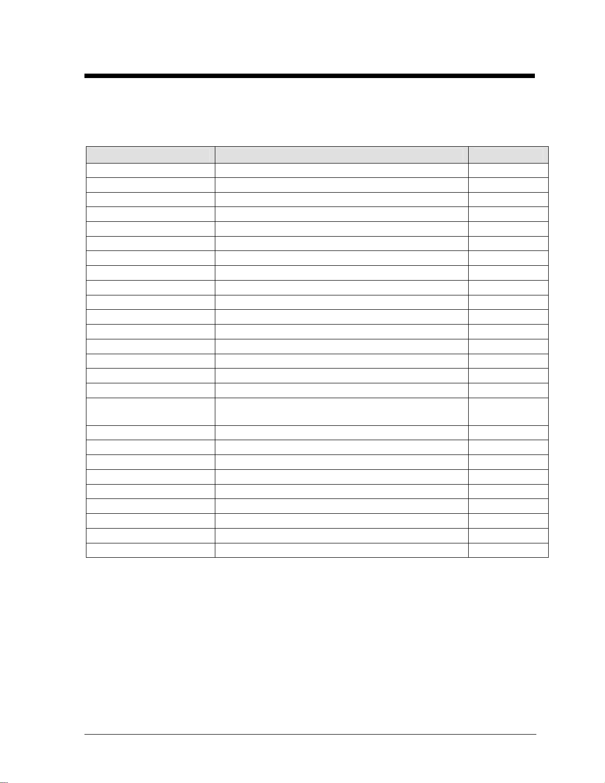
8.8 Replacement Parts
Refer to the following table for Daktronics outdoor scoreboard replacement parts. Refer to Section
9.14 for a listing of parts required for service of the team name message centers. Refer to Section 1.4
for details concerning the Daktronics Exchange and Repair and Return programs.
Important: When the lamp drivers are replaced, plugs P25 and P26 (if present) must be removed
from the old driver and plugged into the new driver.
Description Location
Fuse; AGC-1/2 F17 in lamp driver F-1000
Fuse; AGC-10 F1 - F16 in lamp driver(s) F-1006
Lamp, 25 W, 120 V 3x5 and 24" digits, 15" and 18" 4x7 digits DS-1029
Lamp, 30 W, 130 V 15" 4x7 digits DS-1182
Lamp, 40 W, 120 V Indicators DS-1163
Lamp, 25A19, 230 V frosted Digits and indicators DS-1363
Plug, 1/4" phone Signal P-1003
Socket, med. base lamp All lamps X-1301
Socket*, lamp, med. base,
insulation displacement
J-box, 1/4" phone, Indoor Signal 0A-1009-0038
J-box, 1/4" phone, outdoor Signal 0A-1091-0227
Signal surge arrestor Power/signal entrance enclosure 0P-1033-0114
12 V DC trumpet horn asm. Scoreboard 0A-1091-1213
Lamp driver, 8-column Scoreboard 0A-1033-0126
Lamp driver, 16-column Scoreboard 0A-1033-0125
Lamp driver, 230 V 8-col. Scoreboard 0A-1033-0130
Lamp driver, 230 V 16-col. Scoreboard 0A-1033-0129
Signal cord; 1/4" phone 20’ N/A W-1236
Signal cord; 1/4" phone 30’ N/A W-1238
Signal cord; 1/4" phone 50’ N/A W-1237
18" 4x7 shade screen 18" 4x7 digits or 3x5 digits 0S-1064-0001
All lamps X-1294*
Daktronics
Part No.
8-4
Digit Maintenance
and Troubleshooting
Page 37

Description Location
24" 4x7 shade screen 24" 4x7 digits 0S-1064-0002
15" 4x7 shade screen 15" 4x7 digits or 3x5 digits 0S-1064-0074
30" 4x7 shade screen 30" 4x7 digits 0S-1091-0002
Daktronics
Part No.
*This part, X-1294, is intended for use with scoreboards shipped after October, 2001. Models shipped prior to that
date will continue to use original equipment.
8.9 Troubleshooting
This section lists potential problems with the scoreboard and indicates possible causes and corrective
actions. This list does not include every possible problem, but does represent some of the more
common situations that may occur. Refer to Section 9.13 for a list of potential problems with team
name message centers.
Important: When the lamp drivers are replaced, plugs P25 and P26 (if present) must be removed
from the old driver and plugged into the new driver.
Symptom/Condition Possible Cause or Corrective Action
Scoreboard will not light.
Console not connected or poor connection
No power to the control console
No power to the scoreboard
Bad relay or poor relay connection in signal circuit
Driver logic fuse (F17) blown
P17, P19, or P20 unplugged
Half of the scoreboard will not
light.
Display is garbled.
Digit will not light.
Segment will not light.
Segment stays lit.
Circuit breaker tripped at service panel
Driver malfunction
Poor signal contact at main power connection
Control console malfunction
Internal lamp driver malfunction
Fuse blown in driver
Black wire to the digit damaged
Poor contact at driver connector
Lamps burned out
Driver malfunction (bad triac)
Broken wire between lamp driver and digit
Poor contact at driver connector
Driver malfunction (bad triac)
Segment neutral wire touching case
Digit Maintenance
and Troubleshooting
8-5
Page 38

Page 39

Section 9: Team Name Message Centers
Maintenance and Troubleshooting
IMPORTANT NOTES:
1. Turn power off before doing any repair or maintenance work on the
display!
2. Permit only qualified service personnel to access internal display
electronics.
3. Do not operate the display with the back sheets removed! The cabinet is positively
pressurized, directing adequate airflow around the lamps and out through the lenses.
Display operation without the back sheets in place and fans running could cause damage
to the display and will void the warranty. Make certain the back sheets are fastened
securely into place.
4. Dirt and contaminants may enter the display if it is operated without the fan filters
in place or with dirty fan filters. These contaminants may cause premature failure of
the electronic components. Operating the display with dirty fan filters or without fan filters
will void the warranty.
5. Daktronics product managers or engineering staff must approve any changes that
may affect the weather-tightness of the display. This is to include, but is not limited to,
border shrouding, back sheets, cooling fans, fan filter and filler panels. If ANY
modifications are made to the weather-tightness of the display, detailed drawings MUST
be submitted to our engineering staff for evaluation and approval, or the warranty will be
null and void.
6. Turning the power off when the display is not in use extends the life of some
components.
The team name message centers for standard (not modified for an individual customer) scoreboards
are FRONT-ACCESSIBLE for service. Custom scoreboards may be accessed from the front or rear.
This manual applies to team name message centers used in standard scoreboards.
9.1 TNMC Schematics
Reference Drawings:
Schematic, 832-12 TNMC..................................................................... Drawing A-125214
Schematic, 848-12 TNMC..................................................................... Drawing A-125216
Refer to the team name message center schematic Drawings A-125214 and A-125216 listed in
Section 5.
TNMC Maintenance
and Troubleshooting
9-1
Page 40

9.2 Service Procedures
Reference Drawings:
Lens Removal, Front Access. .................................................................Drawing A-99898
Lens Assy Removal, Front Access ......................................................... Drawing A-99899
Correct Lens Position, 1-1/2" ..................................................................Drawing A-75204
Removing a Module
For many maintenance or repair procedures, the first step is to remove a module. Each 8x16 lens
assembly is secured to the frame by two spring-loaded latches, one on each side. Follow these
instructions for access to these latches:
1. Remove the lens from row 4, column 1, and the lens from row 4, column 16 of the lens
assembly. Refer to Drawing A-99898.
2. Place the front access tool into the latch access hole. The angled edge of the tool should
be down so it wedges the latch pin down as it is pushed further into the access hole. Refer
to Section 9.14 for the part number of the access tool.
3. When the front access tool is fully inserted, the module latches should be released (refer
to Figure 6).
Figure 6: Removing a Module
4. With the latch released, pull the lens assembly slightly away (about
This will prevent it from re-latching. Refer to Drawing A-99899.
5. Repeat this procedure with the remaining side.
6. With both sides unlatched, the assembly should pull away from the display far enough so
the signal and power harness can be disconnected from the lampbank. When the signal
and power harnesses are removed, the module can be removed from the display.
Note: A
3
/16" slotted screwdriver may be used in place of the access tool.
1
/2") from the display.
Removing a Lampbank
The lampbank is attached to the lens assembly with a metal tab at each corner. To remove the
lampbank:
1. Push in the clips while gently pulling the lampbank out.
2. Repeat this step for the three remaining corners. Lampbanks should be serviced in a static-
free area to prevent static electricity from damaging the components.
9-2 TNMC Maintenance
and Troubleshooting
Page 41

Replacing a Lampbank
When lampbanks are reattached to the lens assemblies, be certain the lamp sockets are seated
tightly against the reflectors. All four tabs, one in each corner, must be snapped securely onto the
lampbank. If the lampbank is not secured properly to the lens assembly, the lamp filament will not
be at the focal point of the reflector, and parts of that lens assembly will appear dim.
Replacing the Module
To reinstall a lens assembly in the display, refer to Drawing A-75204:
1. Reconnect power and signal connections to the lampbank.
2. Tilt the module about 30 degrees and place the bottom corners of the side brackets to the
inside of the frame verticals.
3. Push the lens assembly firmly back into place until the latches snap into place and the lens
assembly is secured to the display. It may be necessary to use a solid object, such as a
short length of 2"x4" lumber, to properly seat the assembly. Place the 2x4 across the
louvers so the pressure on them is evenly distributed and strike the board with the heel of
your hand. This should drive the assembly in place.
4. Pull firmly on the assembly to ensure that it is fully in place and secured to the display.
The lens assemblies must fit together tightly enough so the weatherstripping forms a seal
and prevents water from leaking between the lens assemblies and into the display. The
seal between the assemblies should be checked with a 0.032" feeler gauge.
5. Snap the lenses back into the faceplate of the lens assembly. If a lens is not replaced
properly, it is easily noticed. The lens removal tab or the lens itself will not be in
alignment with the other lenses or lens tabs.
6. Verify that the rows of louvers on the lens assembly are in proper alignment.
9.3 Lamp Testing and Replacement
Reference Drawing:
Lens Removal, Front Access. ................................................................. Drawing A-99898
This display is designed for easy lamp replacement with front access. Non-functioning lamps should
always be replaced prior to scheduled events, or as soon as possible, for best viewing.
A 3.58 W lamp is positioned behind each lens. Use the controller lamp test to locate bad lamps. Refer
to Section 9.14 for the part numbers of replacement lamps and lenses.
Daktronics-approved 3.58 W lamps have an estimated life of 17,000 hours if operated at 11.0
V. Always use Daktronics-approved lamps.
K Note: Lamps purchased from Daktronics are built to tighter specifications than similar
lamps built in standard production. The recommended lamps give the sufficient
intensity and beam spread to match the display design. Lamps not built to Daktronics
specifications will not perform as well and will not give the intended results.
A qualified individual who is capable of operating the controller equipment should do lamp
testing.
Display power must be OFF for lamp replacement.
TNMC Maintenance
and Troubleshooting
9-3
Page 42

Individual Lamp Replacement
Grasp the tab on the top center of the lens with the lamp-extracting tool (refer to Drawing A-
99898). Pull the tab out and down, and at the same time, with your other hand, lightly press up on
the louver directly above the lens to be removed. Do not press up on the louver any further than
necessary, or the louver may become deformed.
1. Remove the defective lamp using the lamp-extracting tool.
2. Replace defective lamps with Daktronics approved lamps of the same wattage. Refer to
Section 9.14 for the correct replacement lamps.
3. Noting proper lens orientation, snap the lens back into the lens/reflector assembly (refer to
Section 9.4).
9.4 Lens Position and Sequence
Reference Drawing:
Lens Removal, Front Access. .................................................................Drawing A-99898
The slot in the bottom of the reflector accommodates the lens indexing tabs. To insert a lens, set the
lens tabs into the reflector slots and snap the lens up into the vertical position. Make sure that the lens
is snapped in and behind the upper louver offset.
Inspect the profile of the lenses to ensure that all lenses are secured properly. Lenses that are not
secured properly can be easily noticed, since the lens removal tab or the lens itself will not be in
alignment with the other lenses or lens tabs in that row.
Refer to Drawing A-99898 for more information.
9.5 Lens/Reflector Assembly Maintenance
Reference Drawing:
Lens Assy, Weather Stripping Location ...................................................Drawing A-91100
The lens/reflector assemblies are maintenance-free; however, each time an assembly is removed from
the display, the pile weatherstripping should be checked for signs of deterioration. The
weatherstripping runs along the top and sides of each lens/reflector assembly. In addition, over time,
the louvers on the front of lens/reflector assembly may become damaged and require replacement.
Weatherstripping and louver replacement are addressed in the following subsections.
Weatherstripping Maintenance
The top and bottom of each 8x16 lens assembly has a strip of pile weatherstripping. There is also
tape weatherstripping between each louver assembly. The weatherstripping helps keep moisture
out of the display and maintains the positive air pressure necessary for proper display cooling.
When doing routine display maintenance, which involves removing the 8x16 lens assemblies,
make sure the weatherstripping is intact. If any weatherstripping appears damaged, replace it.
Refer to the following instructions and Drawing A-91100. Refer to Section 9.14 for part
numbers.
1. Once the old weatherstripping has been removed, clean the top and bottom of the lens
assembly with an adhesive remover so the new weatherstripping will adhere.
2. The weatherstripping should be applied in one continuous strip on both the top and
bottom of the lens assembly.
9-4 TNMC Maintenance
and Troubleshooting
Page 43

3. When finished, the stripping should be flush at the bottom. If the weather stripping is not
tight or buckles anywhere on the lens assembly, it will be difficult to reinstall it in the
display, and it will allow water to enter the display and damage the electrical components.
4. Check the module spacing and weather stripping tightness with the 0.032" feeler gauge.
Louver Maintenance
If display louvers become bent or damaged, they must be replaced. The lens/reflector assembly
containing the damaged louvers should be returned to Daktronics for repair or replacement.
9.6 Lamp Module Transformer
Displays with team name message centers are shipped with transformers which, when wired to the 120
V tap with a line voltage of 120 V, will deliver 11.0 volts to the lamp. Lamp life is estimated to be
17,000 hours with this transformer. Refer to Section 9.14 for the correct part number for the
replacement transformer
Due to input line voltage variations from site to site, the resultant lamp voltages may vary, which may
greatly alter lamp life.
If the measured input line voltage is over the particular transformer's rated input voltage, increased
voltage will be delivered to the lamp, and that will greatly reduce lamp life.
The transformer is may be adjusted both up and down if line voltage varies enough to greatly alter
lamp life/lamp brightness.
If the transformer requires adjustments, contact Daktronics Customer Service.
9.7 Fan Filters
Reference Drawing:
Filter Removal; 250 CFM Fan ............................................................... Drawing A-113986
Metal shrouds on the rear of the display house the fan filters and shed rain. Filters must be checked
every 1,500 hours of operation for accumulation of debris that could restrict airflow.
Check filters after the display has been in operation for 1,500 hours—and every 1,500 hours thereafter
– to ensure that the display is being cooled properly. Filters should be checked more often if the
display is located in a dusty or harsh-weather environment (that is, along a gravel road with dust-laden
air). The 1,500 hours is equivalent to 83 days if the display is operated for 18 hours a day and the
power to the display is turned off when it is not in use. (Turning off the power ensures that the fans are
not operating when the display is not running.) If the display is on running non-stop, 24 hours a day,
1,500 hours is equivalent to 72 days.
Daktronics recommends that spare filters be kept on hand at all times. Ideally, all filters should be
replaced during routine maintenance. If a filter media shows evidence of damage or wear, replace the
filter with a Daktronics filter. If a filter other than the Daktronics standard filter is used, follow these
criteria (refer to Section 9.14 for the part number of the filter):
1. Effective filter area must be no less than 2.3 square feet per 1.0 square feet of face area, and
2. Filter media must have an average arrestance of 90-92 percent.
TNMC Maintenance
and Troubleshooting
9-5
Page 44

Once the filters have been replaced, turn power back on. Make sure that the fans are turning properly.
K Note: Turn the power OFF after checking the fans.
Periodically check airflow through the lenses to ensure that there are no obstructions in the lens
exhaust holes. Airflow is necessary to adequately cool the lenses and lamps. Keep the interior of the
module clean to prevent a buildup of dust on the lenses. Use an air hose and a vacuum cleaner to keep
the display clean. Inspect the cabinet seal periodically to make certain it is sealing properly. If you
detect leaks, repair or replace the pile weatherstripping seal around the edges of the cover.
Used this method for checking both the airflow through the lenses and the cabinet seal:
Direct smoke toward the fan inlet and note where the smoke exits.
Check all around the cabinet and the lenses. If smoke does not exit a particular group of
lenses, remove the lenses to clean out any debris, replace the lenses and retest.
9.8 Filter Removal
Reference Drawing:
Filter Removal; 250 CFM Fan............................................................... Drawing A-113986
Follow the steps on Drawing A-113986 to remove the filter from the scoreboard. Check the fan as
follows:
1. Inspect the filter and determine if it should be replaced or cleaned.
2. Inspect the filter assembly perimeter gasket for evidence of deterioration or air leakage around
or through the gasket. The factory-applied gasket is at the top of the rain shield assembly and
to the front of the filter holder. The gasket is also on the 16" sides of the filter. If any part of
the gasket material is damaged and needs to be replaced, refer to Section 9.14 for the part
number of the gasket material.
3. Insert a filter into the filter holder.
4. Inspect the filter assembly. Make certain that the filter is touching the inside of the frame
throughout its entire length and that no air gaps exist. Ensure that the filter assembly is set
inside the channel on the topside and is resting in the filter holder. Make sure that the filter
wire side is up.
5. Inspect the filter holder to ensure the weatherstripping is providing a tight fit around the
perimeter of the rain shield.
6. Replace the filter cover plate if that was removed (front access).
9.9 Fans
Fans are provided to control the heat buildup generated by the electronic components. One cooling fan
is provided for every three modules (8x16 display modules).
Check fans after the display has been in operation for 1,500 hours−and every 1,500 hours
thereafter−to ensure the display is being cooled properly. Fans should be checked more often if the
display is located in a dusty or harsh environment (i.e., along a gravel road with dust-laden air).
9-6 TNMC Maintenance
and Troubleshooting
Page 45

As noted previously, 1,500 hours is equivalent to 83 days if the display is operated for 18 hours a day
and the power to the display is turned off when not in use. (This ensures that the fans are not operating
when the display is not running.) If the displays is running non-stop, 24 hours a day, 1,500 hours is
equivalent to 62 days.
Each time a module is removed, take time to inspect the fans.
1. Check the fan blades for dirt and debris. If the fan blades have a large accumulation of dirt
and debris, this indicates that the filters need to be changed more often. Fan blades must be
kept clean to maintain fan efficiency and ensure proper cooling.
2. Spin the fan blades with a pen or pencil to ensure that the bearings are free and the fan is still
in balance.
After 10 percent of the fans have been replaced, Daktronics recommends replacing all fans to reduce
associated maintenance costs that may incur with increased heat buildup from fan failure.
A fan-testing power cord is available for checking fan operation. Plug the test cord into the
questionable fan and plug the other end into a 110 V outlet. If the fan does not turn or does not operate
smoothly, replace it. Use extreme caution during this testing, since the fan blades are exposed!
K Note: If the display is not in operation, turn power off to conserve energy and extend the life of
both the fans and electronic components.
9.10 Lens Airflow
Check airflow through the lenses
periodically to ensure there are no
obstructions in the lens exhaust
holes. Airflow is necessary to cool
the lenses and lamps adequately
(refer to Figure 7). The interior of
the module should be kept clean to
prevent a buildup of dust on the
lenses. Use an air hose and a
vacuum cleaner to keep the display
clean.
Inspect the cabinet seal periodically
to make certain it is sealing
properly. If leaks are detected,
repair or replace the pile weather
stripping seal in the area where the
leak occurred. Use the following method to check both the airflow through the lenses and the cabinet
seal:
1. Direct smoke toward the fan inlet and observe where the smoke exits.
2. Check all around the cabinet and the lenses.
3. If smoke does not exit a particular group of lenses, remove the lenses to clean out any debris,
replace the lenses and re-test.
Figure 7: Lens Airflow
TNMC Maintenance
and Troubleshooting
9-7
Page 46

9.11 Structural Inspection
Perform a visual inspection annually. Check the paint and look for possible corrosion, especially at
footings, structural tie points, and ground rods. Fasteners should be checked and tightened or replaced
as required.
At least once a year, check the inside of the display for signs of water intrusion (for example, water
stain marks). Water can enter a display where weatherstripping has come loose or deteriorated.
Fasteners may also have loosened, allowing moisture to enter through seams in the display. Check the
top of the display around the eyebolts to insure that no moisture may enter through loosened fixtures.
Check electronic components closely for signs of corrosion.
9.12 Cleaning the Signal Connectors
If it becomes necessary to remove or replace a signal cable, clean the plugs and the circuit board jacks
with Deoxit
thoroughly to ensure the absence of any foreign matter. The presence of dirt or water may cause signal
interconnect problems.
After the parts are cleaned, push the plug into a jar of Cailube
number), ensuring that the paste wets the plug to a depth of at least
make sure that all of the pin holes of the plug are filled with paste and that sufficient paste is present to
form a "V" on the end of the plug. There should be enough paste on the end of the plug to form a
weatherproof seal (from paste pushed out around the jack) when the plug is inserted into the circuit
board jack.
Deoxit
lubricant and protector paste in a 1oz jar. Both can be found in the Tool Kit Accessories package.
Cailube also comes in an 8 oz jar (refer to Section 9.14 for the part number). If you need additional
supplies, contact Customer Service for ordering information.
(refer to Section 9.14 for the part number). Inspect and clean the jacks and plugs
(refer to Section 9.14 for the part
1
/8" on all four sides. Also check to
™
is the electrical contact cleaner in an aerosol can, and Cailube™ is the electrical contact
9.13 Troubleshooting
This section contains some symptoms that may be encountered in team name message centers. For
these symptoms, possible causes and corrective actions are suggested. This list does not include every
possible problem, but does represent some of the more common situations that may occur. Refer to
Section 8.9 for a list of potential scoreboard problems.
Symptom/Condition Possible Cause/Remedy
One or more lamps on display will not
light.
One or more lamps will not turn off.
Replace lamp
Replace socket
Replace lampbank
Check for foreign objects on PC board
Replace lampbank
9-8 TNMC Maintenance and Troubleshooting
Page 47

Symptom/Condition Possible Cause/Remedy
Entire module does not work.
Section of display does not work.
Entire display does not work.
Check signal connection (ribbon cable)
Check power connections
Check transformer fuse on panel
Replace lampbank
Check appropriate main fuse or breaker.
Check 120 V AC input power to sign.
Check all signal connections.
Check controller output.
9.14 Replacement Parts List
Refer to the following table for Daktronics scoreboard replacement parts. Refer to Section 8.8 for a
listing of parts required for the service of the scoreboards. Refer to Section 1.4 for Daktronics
Exchange and Repair and Return programs.
Part Description Daktronics Part No.
Monochrome lens/reflective assembly 0A-1176-0002
Vertical shift interface board
(Attached to master module; operated by All Sport
Current loop interface (CLI) board
(Attached to master module; operated by ProSport
Controller board 0A-1146-0007
Electrical contact lubricant and protector (paste) 8oz jar CH-1021
Controller)
controller)
0P-1176-0006
0P-1176-0004
Fan, 120 V, 250 CFM B-1019
Fan filter L-98614
Fuse, MDL-7, 1/4" by 1 ¼", Slow-Blo F-1031
Lamp; T-3¼, wedge base, xenon-filled DS-1241
8x16-10 lampbank; 1.5" S1600 monochrome 0P-1176-0002
Lens, mono white DS-1235
Socket; T3 1/4 wedge X-1209
Tool kit accessories (includes the following) 0A-1176-0008
Electrical contact cleaner (spray can) CH-1015
Electrical contact lubricant and protector (paste) 1 oz
jar
Front access module remover tool 0M-95442
Lamp extractor TH-1032
Lamp voltage tester 0P-1089-0010
TNMC Maintenance
and Troubleshooting
CH-1019
9-9
Page 48

Part Description Daktronics Part No.
Rear access module remover tool 0M-95441
0.032 feeler gauge, weatherstripping 0M-69133
Transformer, 120 V T-1107
Weatherstripping, pile HS-1149
Weatherstripping, tape HS-1051
Weatherstripping, open cell, filter assembly HS-1039
9.15 TNMC Exchange and Repair and Return Programs
Refer to Section 1.4 for information concerning Daktronics Exchange and Repair and Return
programs.
9-10 TNMC Maintenance
and Troubleshooting
Page 49

Section 10: Scoreboard Options
The following options are available for Daktronics outdoor scoreboards to make the displays more
adaptable to scoring and timing needs:
Team name caption kits for certain models.
Trumpet horn for football and soccer.
Remote start/stop console.
10.1 Team Name Captions – Models BA-624, BA-1518 and BA-1524
Reference Drawing:
Caption Changing ...................................................................................Drawing A-44549
The team name caption kit contains hardware for one caption only and consists of an upper caption
retainer, a lower caption retainer, a changeable caption panel, and screws.
The standard Guest and Home captions are applied directly to the face of the scoreboard. Team name
captions are on changeable panels that fit into retainers mounted above and below the Home and
Guest captions. If retainers are not already present on your scoreboard, attach the retainers included
with your caption kit as shown on Drawing A-44549.
To install a changeable panel:
1. Insert the top of the panel into the upper retainer.
2. Lift the panel all the way up into the retainer.
3. Insert the bottom of the panel into the lower retainer.
Reverse this procedure to remove the caption panel.
An optional caption changer is available for installing and removing panels from the ground. Each
panel is punched with keyholes. Screw-heads on the crossbar at the top of the caption changer fit into
the keyholes. The caption changer pole consists of three sections and an adjusting ring that may be
loosened to extend the pole. After extending the pole to the desired length, tighten the ring.
CAUTION
The aluminum caption changer can conduct electricity. Do not use it
within 20' of power lines.
Be careful when using the caption changer in high or gusting winds.
Wind may catch the panel and unhook it from the changer.
The surface area of the caption panel could act as a sail, making it
difficult to keep a grip on the pole. In high or gusting winds, hold the
pole very tightly and be careful to maintain your balance when using
the caption changer.
Scoreboard Options 10-1
Page 50

10.2 Trumpet Horn
Reference Drawings:
Horn Installation ...................................................................................... Drawing A-44197
Final Assembly, 12V DC Horn Mounting................................................. Drawing A-83333
Schematic; Football Trumpet Horn ......................................................... Drawing A-83329
The trumpet horn options are available only with scoreboards that have clocks. The two types of
trumpet horns are:
Internally mounted AC trumpet horn.
Externally mounted DC trumpet horn.
AC Trumpet Horn Installation (Internally Mounted) Caution: Disconnect the power before installing the horn!
Refer to Drawing A-44197.
1. Unscrew and remove the trumpet from the horn body.
2. Mount the horn body to the bracket with the
horn is oriented so that the wire opening is at the bottom.
3. Attach the relay to the bracket with the #10 hardware.
4. Mount the ground lug below the horn with a
5. Insert the green wire from the horn into the ground lug and tighten.
6. Connect one black wire from the horn to the white wire from the relay.
7. Connect the other black wire to the red wire from the relay. Use the wire nuts provided to
make this connection.
8. Locate the horn panel in the scoreboard. Refer to the component location drawings in
Section 4. Note that there is a 2" knockout in this panel.
9. Loosen the screws securing the bottom of the panel and swing it open.
10. Mount the bracket to the bottom frame member using #10 screws. There are two holes in
the frame for this purpose.
11. Connect the wires with a white plug to the mating jack marked HORN on the left side of
the entrance enclosure.
12. Close and secure the access panel.
13. Screw the trumpet into the horn body. The trumpet will tilt down about 10 degrees to
allow moisture drainage.
14. Connect to power to the scoreboard.
15. Connect the control console to the scoreboard.
16. Test the horn by pressing the key labeled HORN on the control console.
1
/4" bolts and nuts provided. Be sure that the
1
/4" bolt and nut.
DC Trumpet Horn Installation (Externally Mounted)
Caution: Disconnect the power before installing the horn!
Refer to Drawing A-83333.
1. Locate the horn panel in the scoreboard. Refer to the component location drawings in
Section 4. Note that there is a 2" knockout in this panel.
2. Loosen the screws securing the bottom of the panel and swing it open.
3. Drill two
10-2 Scoreboard Options
5
/32" holes 4" apart near the entrance enclosure.
Page 51

4. Attach the horn enclosure to the inside of the scoreboard over the
5
/32" holes using #10
tapping screws.
5. Attach the plate assembly to the horn enclosure using the #10 hardware provided.
6. Remove the 2" knockout in the horn panel.
7. Drill two
knockout exists, use the template to drill one
7
/32" on either side of the knockout using the template Drawing A-83502. If no
8
/32" hole and two 7/32" holes in the panel.
8. Thread the two gray wires form the horn through the top of the mounting angle.
9. Attach the horn to the mounting angle using the #10 hardware provided
10. Insert the bushing into the
11. Attach the horn/angle assembly to the panel over the 2" knockout and
3
/8" hole in the mounting angle.
7
/32" holes using the
#10 hardware provided.
12. Open the panel and remove the cover from the horn enclosure.
13. Use the wire nuts provided to one gray wire from the horn to the black wire from the plate
assembly. Connect the second gray wire from the horn to the red wire from the plate
assembly.
14. Connect the wires with a white plug to the mating jack marked HORN on the left side of
the entrance enclosure.
15. Close and secure the access panel.
16. Connect to power to the scoreboard.
17. Connect the control console to the scoreboard.
18. Test the horn by pressing the key labeled HORN on the control console.
Scoreboard Options 10-3
Page 52

Page 53

Appendix A: Reference Drawings
A Drawings
Digit Service.................................................................................................. Drawing A-27674
Horn Installation ............................................................................................Drawing A-44197
Display Mounting ..........................................................................................Drawing A-44412
Lifting Scoreboard......................................................................................... Drawing A-44548
Caption Changing ......................................................................................... Drawing A-44549
Digit Segments, 3x5 and 4x7 ........................................................................Drawing A-46653
Ad Panel Mounting ............................................................................. Drawing A-52187
Assembly, Ad Panel, BA-515........................................................................ Drawing A-52585
Ad Panel Mounting, BA-518.......................................................................... Drawing A-52811
Installation Specifications, BA 515................................................................ Drawing A-55003
Installation Specifications, BA 518................................................................ Drawing A-55004
Installation Specifications, BA 718................................................................ Drawing A-55005
Installation Specifications, BA 618................................................................ Drawing A-55006
Installation Specifications, BA 624................................................................ Drawing A-55007
Installation Specifications, MS 918 ............................................................... Drawing A-55009
Installation Specifications, SO 918 ...............................................................Drawing A-55010
Scoreboard Mounting.................................................................................... Drawing A-55101
Lifting Small Baseball Scoreboard ................................................................Drawing A-58668
Installation Specifications, BA 1018.............................................................. Drawing A-61904
Correct Lens Position, 1-
Schematic; Football Trumpet Horn ...............................................................Drawing A-83329
Final Assembly, 12V DC Horn Mounting....................................................... Drawing A-83333
Lens Assy, Weather Stripping Location ........................................................Drawing A-91100
Lens Removal, Front Access. .......................................................................Drawing A-99898
Lens Assy Removal, Front Access ...............................................................Drawing A-99899
Components
Installation Specifications, MS-915 .............................................................Drawing A-113568
Filter Removal, 250 CFM Fan..................................................................... Drawing A-113986
Layout, 16 Column Driver III .......................................................................Drawing A-123940
Layout, 8 Column Driver III .........................................................................Drawing A-123941
Schematic; 2 Drivers................................................................................... Drawing A-124291
Schematic; 1 Driver .................................................................................... Drawing A-124293
Schematic; 1 Driver Overseas ....................................................................Drawing A-124296
Schematic; 1 Driver 8 Column ....................................................................Drawing A-124298
Single-Section Scoreboard Models............................................................. Drawing A-124342
Component Locations, MS-918 ..................................................................Drawing A-124343
Schematic, 832-10 TNMC........................................................................... Drawing A-125214
Schematic, 848-10TNMC............................................................................ Drawing A-125216
Components 2/4 Pos Power and Signal Entrance...................................... Drawing A-125977
Component Locations, BA-515 ...................................................................Drawing A-126083
Component Locations, BA-518 ...................................................................Drawing A-126084
Component Locations, BA-618 ...................................................................Drawing A-126221
Component Locations, BA-624 ...................................................................Drawing A-126285
Component Locations, BA-718 ...................................................................Drawing A-126306
Component Locations, BA-1018 .................................................................Drawing A-126353
Component Locations, TI-218..................................................................... Drawing A-126364
Component Locations, TI-418..................................................................... Drawing A-126372
8
/16 Pos Power and Signal Entrance ......................................Drawing A-109114
1
/2".......................................................................... Drawing A-75204
Reference Drawings A-1
Page 54

Component Locations, CT-2001 .................................................................Drawing A-126429
Component Locations, CT-2002 .................................................................Drawing A-126430
Component Locations, FB-824 ................................................................... Drawing A-126431
Component Locations, MS-915 ..................................................................Drawing A-126432
Component Locations, S0-918 ...................................................................Drawing A-126433
Component Locations, TI-2003................................................................... Drawing A-126434
Component Locations, MS-2002 w/TNMC ................................................. Drawing A-127193
Installation Specifications, MS-2002 ........................................................... Drawing A-127195
Component Locations, MS-2002 ................................................................ Drawing A-127235
Single-Section Scoreboard Models w/TNMC.............................................. Drawing A-127262
Component Locations, S0-824 ...................................................................Drawing A-127285
Installation Specifications, FB-824 & SO-824 ............................................. Drawing A-127287
Component Locations, MS-2004 ................................................................ Drawing A-128047
Incandescent Driver Power Up Self-Test.................................................... Drawing A-128283
Power Up Self Test on a FB-1424 .............................................................. Drawing A-128301
Installation Specifications, MS-2004 ........................................................... Drawing A-128788
Component Locations, MS-2006 w/TNMC ................................................. Drawing A-132960
Installation Specifications; MS-2011 w/TNMC ............................................Drawing A-135414
Installation Specifications, MS-2006 ........................................................... Drawing A-135575
Component Locations, MS-2002 w/TNMC & 40W Lamps.......................... Drawing A-135738
Component Locations, FB-2340 ................................................................. Drawing A-137679
Component Locations; MS-2011 ................................................................ Drawing A-138889
Installation, TI-2003 ....................................................................................Drawing A-139316
Schematic; 1 Driver 240V ........................................................................... Drawing A-139639
Schematic, 1 8 Col Driver 240V.................................................................. Drawing A-139733
Installation Specifications, SO-2008 ........................................................... Drawing A-149074
Component Locations; SO-2008 w/ 832-12 TNMC .................................... Drawing A-150127
Component Locations; BA-2004 .................................................................Drawing A-152733
Installation Specifications; BA-2004 & BA-2005 ......................................... Drawing A-152777
Single Section Scoreboard Models............................................................. Drawing A-152945
Component Locations, BA-2003 .................................................................Drawing A-158315
Installation Specifications, BA-2003............................................................ Drawing A-158322
Installation Specifications; TI-2003 ............................................................. Drawing A-169367
Installation Specifications; TI-218 ............................................................... Drawing A-169376
Installation Specifications; TI-418 ............................................................... Drawing A-169380
Installation Specifications; FB-2340............................................................ Drawing A-169388
B Drawings
Schematic; 1 Drvr with 32 or 48-10 TNMC ................................................. Drawing B-127394
Schematic; 2 Drvrs with 32 or 48-12 TNMC ............................................... Drawing B-132144
Schematic; BA-2004 ................................................................................... Drawing B-155111
A-2 Reference Drawings
Page 55

Page 56

Page 57

Page 58

Page 59

Page 60

Page 61

Page 62

Page 63

Page 64

Page 65

Page 66

Page 67

Page 68

Page 69

Page 70

Page 71

Page 72

Page 73

Page 74

Page 75

Page 76

Page 77

Page 78

Page 79

Page 80

Page 81

Page 82

Page 83

Page 84

Page 85

Page 86

Page 87

Page 88

Page 89

Page 90

Page 91

Page 92

Page 93

Page 94

Page 95

Page 96

Page 97

Page 98

Page 99

Page 100

 Loading...