

Page 1
Models
*
BA-2515-31
*
FB-4005-31
*
BA-2618-31
*
BA-2715-31
*
MS-3918-31
*
BA-2718-31
*
SO-2918-31
*Discontinued
DistaView™ Outdoor
LED Scoreboards
Display Manual
DD1698442 Rev 0 – 8 December 2009
201 Daktronics Drive PO Box 5128 Brookings, SD 57006-5128
Tel: 800-325-8766 605-697-4300 fax: 605-697-4700
www.daktronics.com helpdesk@daktronics.com
Page 2

Page 3

DD1698442
Please fill in the information below to use for reference when calling Daktronics for assistance.
Display Serial No. _______________________________________________________
Display Model No. _______________________________________________________
Date Installed ___________________________________________________________
Product 1192
Rev 0 – 8 December 2009
DAKTRONICS, INC.
Copyright 2009
All rights reserved. While every precaution has been taken in the preparation of this manual, the publisher
assumes no responsibility for errors or omissions. No part of this book covered by the copyrights hereon may be
reproduced or copied in any form or by any means – graphic, electronic, or mechanical, including photocopying,
taping, or information storage and retrieval systems – without written permission of the publisher.
All trademarks used in this manual are the property of their respective owners.
Page 4

Page 5

Table of Contents
Table of Contents .................................................................................................................................. i
Section 1: Introduction ................................................................................................................. 3
1.1 Resources .................................................................................................................................. 3
1.2 Daktronics Nomenclature ...................................................................................................... 4
1.3 Model Number ........................................................................................................................ 5
1.4 Scoreboard Controllers ........................................................................................................... 5
1.5 Product Safety Approval........................................................................................................ 5
Section 2: Specifications ............................................................................................................. 7
Section 3: Mechanical Installation .............................................................................................. 9
3.1 Installation Specifications ...................................................................................................... 9
3.2 Lifting the Scoreboard ............................................................................................................ 9
3.3 Scoreboard Mounting ........................................................................................................... 11
Scoreboard Mounting Using Spacers .......................................................................... 12
3.4 Scoreboard Protective Devices ............................................................................................ 12
3.5 Ad Panel Mounting............................................................................................................... 13
Side Ad Panels ................................................................................................................ 13
Top & Bottom Ad Panels .............................................................................................. 14
Section 4: Electrical Installation ................................................................................................ 15
4.1 Installation Overview ........................................................................................................... 15
4.2 Power & Signal Routing ....................................................................................................... 16
Grounding ....................................................................................................................... 16
Termination .................................................................................................................... 17
Fiber Optic ...................................................................................................................... 18
4.3 Power-On Self-Test (POST) ................................................................................................. 19
Radio Settings ................................................................................................................. 19
4.4 Lightning Protection ............................................................................................................. 19
Section 5: Scoreboard Maintenance & Troubleshooting ........................................................ 21
5.1 Component Access ................................................................................................................ 21
5.2 Component Locations ........................................................................................................... 21
5.3 Replacing Digits .................................................................................................................... 22
5.4 Transformers .......................................................................................................................... 22
Replacing a Transformer ............................................................................................... 22
5.5 LED Drivers ........................................................................................................................... 23
Replacing a Driver ......................................................................................................... 25
Setting the Driver Address ........................................................................................... 25
5.6 Replacement Parts ................................................................................................................. 26
5.7 Troubleshooting .................................................................................................................... 26
5.8 Daktronics Exchange and Repair & Return Programs ..................................................... 27
Exchange Program ......................................................................................................... 27
Before Contacting Daktronics....................................................................................... 27
Page 6

Repair & Return Program ............................................................................................. 28
Shipping Address ........................................................................................................... 28
Daktronics Warranty and Limitation of Liability ...................................................... 28
Section 6: Scoreboard Options .................................................................................................. 29
6.1 Changeable Team Name Captions ..................................................................................... 29
6.2 Radio Control ......................................................................................................................... 30
6.3 Portable Power Pack ............................................................................................................. 30
Appendix A: Reference Drawings .................................................................................................. 31
Appendix B: Daktronics Warranty and Limitation of Liability .................................................... 33
Page 7
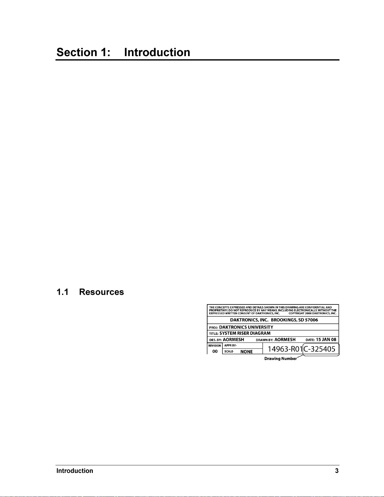
Figure 1: Daktronics Drawing Label
This manual explains the installation of Daktronics single-section DistaView™ outdoor LED
scoreboards. For additional information regarding the safety, installation, operation, or service of this
system, refer to the telephone numbers listed in Section 5. This manual is not specific to a particular
installation.
Important Safeguards:
Please read and understand all instructions before beginning the installation process.
Do not drop control equipment or allow it to get wet.
Do not disassemble control equipment or electronic controls of the display; failure to
follow this safeguard will make the warranty null and void.
Disconnect display power when not in use or when servicing.
Disconnect display power before servicing power supplies to avoid electrical shock.
Power supplies run on high voltage and may cause physical injury if touched while
powered.
Do not modify the scoreboard structure or attach any panels or coverings to the
scoreboard without the express written consent of Daktronics, Inc.
Project-specific information takes precedence over any other general information found in
this manual.
Figure 1 illustrates a Daktronics drawing
label. The drawing number is located in the
lower-right corner of a drawing. This
manual refers to drawings by listing the last
set of digits and the letter preceding them.
In the example, the drawing would be
referred to as Drawing C-325405.
Reference Drawing:
System Riser Diagram ........................................................................... Drawing C-325405
Daktronics identifies manuals by the DD or ED number located on the cover page of each
manual. For example, this manual would be referred to as DD1698442.
Page 8
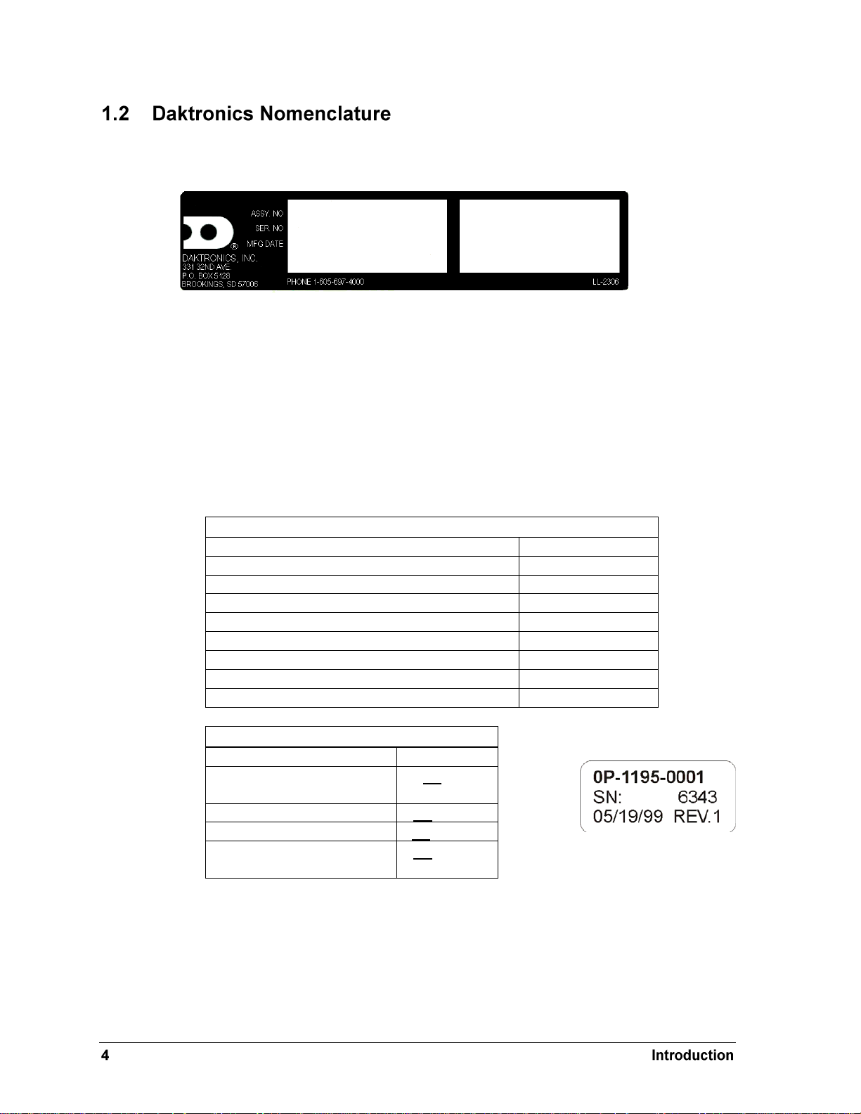
Main Component Labels
Part Type
Part Number
Individual circuit board
0P-XXXX-XXXX
Assembly; a collection of circuit boards
0A-XXXX-XXXX
Wire or cable
W-XXXX
Fuse
F-XXXX
Transformer
T-XXXX
Metal part
M-XXX
Fabricated metal assembly
0S-XXXXXX
Specially ordered part
PR-XXXXX-X
Accessory Labels
Component
Label
Termination block for power
or signal cable
TBXX
Grounding point
EXX
Power or signal jack
JXX
Power or signal plug for the
opposite jack
PXX
Figure 2: Scoreboard ID Label
Figure 3: Typical Label
The serial and model numbers of a Daktronics scoreboard can be found on the ID label on the
display as shown in Figure 2.
Please list the model number, display serial number, and the date this display became
operational in the blanks provided on the second page of this manual. When calling
Daktronics customer service, please have this information available to ensure the request is
serviced as quickly as possible.
Most components within this display carry a white label that lists the part number of the unit.
If a component is not found in the Replacement Parts List in Section 5.6, use the label to order
a replacement. Figure 3 illustrates a typical label. The part number is in bold. The naming
conventions below are also helpful for identifying components within a drawing.
Following the Replacement Parts List is the Daktronics Exchange Policy and the Repair &
Return Program. Refer to these instructions if replacing or repairing any display component.
Page 9
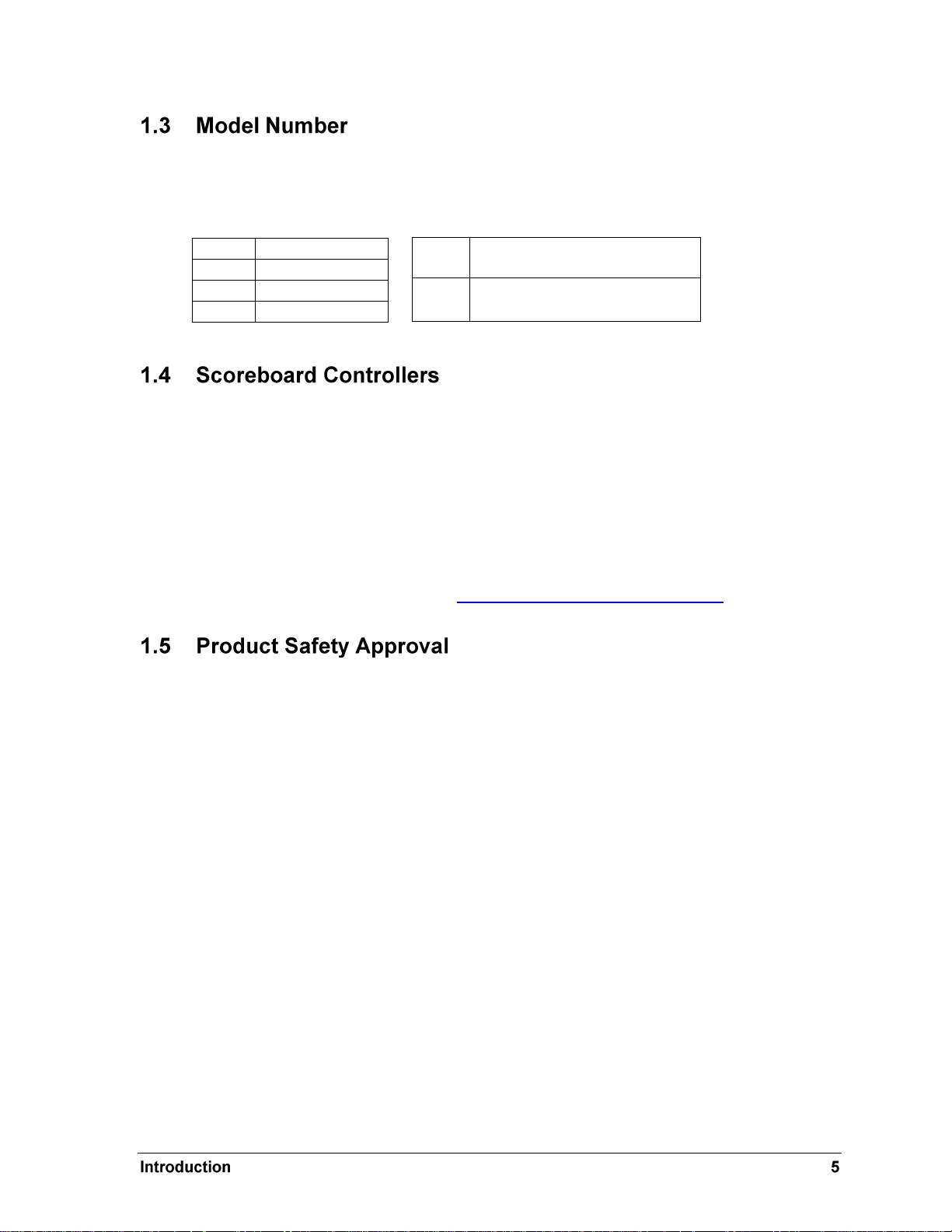
BA
Baseball
FB
Football
MS
Multisport
SO
Soccer
-31
outdoor scoreboards, 120 V,
with red DistaView digits
-32
outdoor scoreboards, 240 V,
with red DistaView digits
Daktronics outdoor DistaView scoreboards are differentiated by their model numbers and
two-letter prefixes for each sport. Most Daktronics scoreboards also carry a two-number
suffix that refers to indoor-outdoor status, power supply and digit color.
Daktronics outdoor DistaView scoreboards are designed for use with the All Sport® 1600 and
5000 series control consoles, and certain models may also be controlled with the RC-100
handheld controller. All controllers use keyboard overlays (sport inserts) to control numerous
sports and scoreboard models. Refer to the following manuals for operating instructions:
All Sport 1600 Series Control Console Operation Manual (ED-12462)
All Sport 5000 Series Control Console Operation Manual (ED-11976)
Remote Control System RC-100 Operational Overview (ED-15133)
These manuals are available online at http://www.daktronics.com/manuals.
Daktronics outdoor scoreboards are ETL listed and tested to CSA standard for outdoor use.
Contact Daktronics with any questions regarding testing procedures.
Page 10

Page 11
Model
Dimensions:
Height, Width, Depth
Weight
Maximum
Wattage
Amps
Driver #
and Address
BA-2515-31
H3'-0", W6'-0", D6"
(914 mm, 1829 mm, 152 mm)
75 lb
(34 kg)
100 W
0.9 A
A1 61
BA-2618-31
H5'-0", W10'-0", D6"
(1524 mm, 3048 mm, 152 mm)
115 lb
(52 kg)
100 W
0.9 A
A1 61
BA-2715-31
H3'-0", W9'-0", D6"
(915 mm, 2743 mm, 152 mm)
100 lb
(45 kg)
100 W
0.9 A
BA-2718-31
H5'-0", W10'-0", D6"
(1524 mm, 3048 mm, 152 mm)
115 lb
(52 kg)
100 W
0.9 A
A1 62
FB-4005-31
H5'-0", W10'-0", D6"
(1524 mm, 3048 mm, 152 mm)
115 lb
(52 kg)
200 W
1.7 A
A1 11
MS-3918-31
H5'-0", W10'-0", D6"
(1524 mm, 3048 mm, 152 mm)
115 lb
(52 kg)
200 W
1.7 A
A1 11
SO-291831/32
H5'-0", W10'-0", D6"
(1524 mm, 3048 mm, 152 mm)
115 lb
(52 kg)
200 W
1.7 A
(0.83 A for
240 V AC)
A1 11
This section lists the mechanical specifications, circuit specifications and maximum power
requirements for each scoreboard model in this manual in alphanumeric order.
Models with a “-31” suffix operate at 120 V AC.
Models with a “-32” suffix operate at 240 V AC.
Note: Driver address setting can be configured using the J19 address plug. Also, the S1 dip switch is
found in all Gen IV drivers. For more details see Section 5.5.
A1 62
Page 12

Page 13
Model
Drawing #
No Ad Panels
1 Ad Panel
2 ad Panels
BA-2515-31
A-222869
A-222872
A-222875
BA-2618-31
A-206385
A-206433
A-206437
BA-2715-31
A-229969
A-229970
N/A
BA-2718-31
A-206385
A-206433
A-206437
FB-4005-31
A-206385
A-206433
A-206437
MS-3918-31
A-206385
A-206433
A-206437
SO-2918-31/32
A-206385
A-206433
A-206437
Note: Daktronics does not assume any liability for any installation derived from the information
provided in this manual or installations designed and installed by others.
Mechanical installation consists of installing concrete footing and steel beams and mounting the
scoreboard and accompanying ad panels to the beams.
The column and footing size dimensions are to assist with estimating installation costs. They are
estimates only and are not intended for actual construction purposes. Be sure that the installation
complies with local building codes and is suitable for the particular soil and wind conditions. The
columns, footings, and all connection details must be designed and certified by a professional
engineer licensed to practice in the state of the scoreboard installation.
The installation specification drawings below are located in Appendix A: Reference
Drawings, presented in alphanumeric order by drawing number.
Larger scoreboard sections and message centers are shipped equipped with eyebolts used to
lift them. The eyebolts are located along the top of the cabinet for each scoreboard or
scoreboard section. Daktronics scoreboards use 1/2" and 5/8" shoulder-type eyebolts mounted
to a 1/8" aluminum plate or steel nut plate
Daktronics strongly recommends using a spreader bar, or lifting bar, to lift the display.
Spreader bars ensure the force on the eyebolts remains straight up, minimizing lifting stress.
Page 14
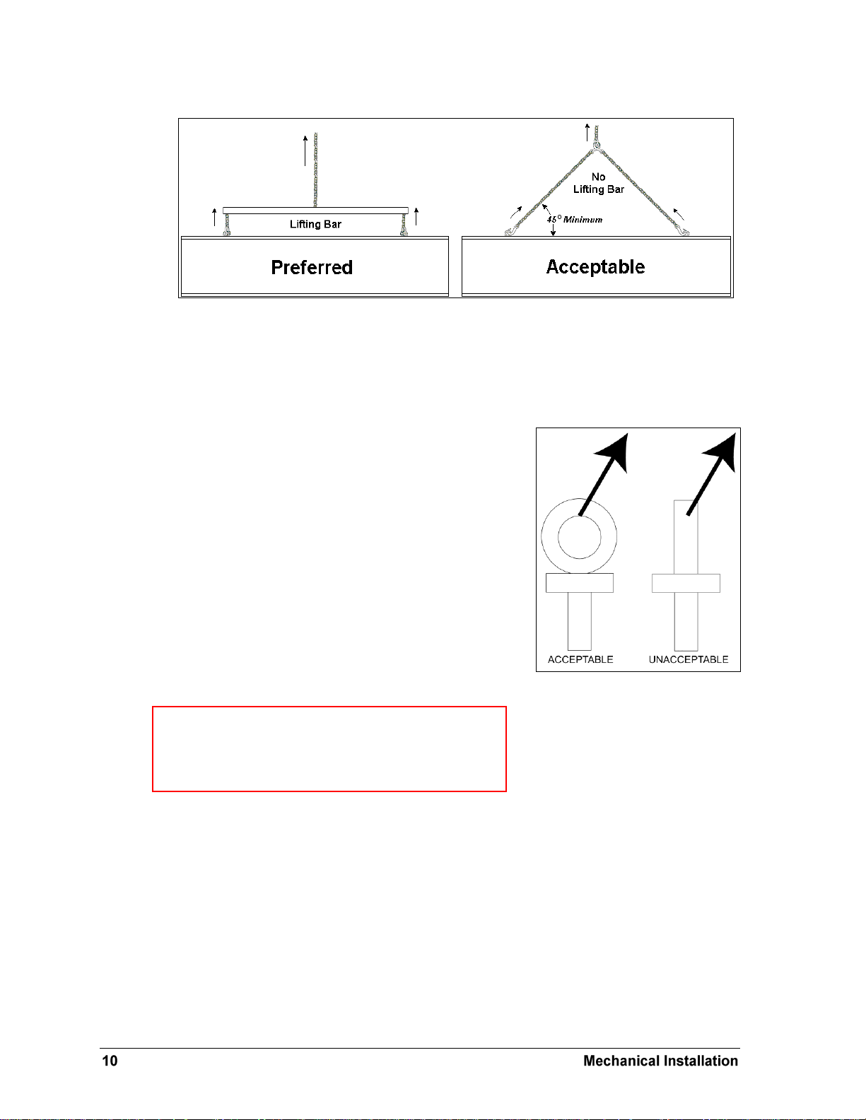
Figure 4: Lifting Methods
Figure 5: Eyebolt Plane Load
Note: Daktronics assumes no liability for damages
resulting from incorrect setup or lifting methods.
Eyebolts are intended for lifting only. Do not attempt to
permanently support the display by the eyebolts.
Figure 4 illustrates the preferred scoreboard lifting method on the left and an acceptable
alternative lifting method on the right. When lifting the display:
Use a spreader bar if possible.
Use every lifting point provided.
Cables and chains attached to the eyebolts and directly to a
center lifting point, as shown in the right-hand example in
Figure 4, can create a dangerous lateral force on the
eyebolts and may cause the eyebolts to fail. The smaller the
angle between the cable and the top of the display, the
lighter the sign must be to safely lift it. If this method must
be used, ensure a minimum angle between the chain and
scoreboard of at least 45 degrees. Do NOT attempt to lift
the display if the angle is less than 45 degrees.
Exceeding load angles or weight limits could cause the
bolts in the scoreboard cabinet to buckle, resulting in
serious damage to the scoreboard or injury to personnel.
Also, loads should be applied directly in the plane of the
eyebolt as shown in Figure 5.
If installers remove the eyebolts, plug the holes with bolts and the rubber washers that are
used with the eyebolts. Apply silicone or another waterproof sealant to the eyebolt openings.
Also inspect the top and sides of the display for any other holes or openings that may allow
moisture to enter the display and plug and seal those openings.
Small Daktronics scoreboards are not equipped with eyebolts, and instead use two lifting
straps that encircle the scoreboard. It is recommended to use a spreader bar with the straps.
Page 15
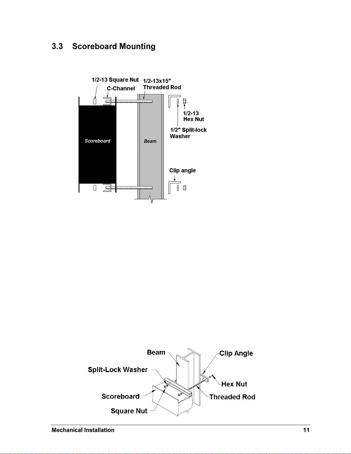
Figure 6: C-channel Mounting Method, Side View
Figure 7: C-channel Mounting, Isometric View
An inverted channel mounting installation uses C-channels; clip angles; 1/2-13" threaded
rods; and 1/2" square nuts, hex nuts, and lock washers (Figure 6 & Figure 7).
Mount the scoreboard as follows:
1. Place the C-channel against the upper and lower rear flanges of the scoreboard.
2. Use the width of the beam to determine the appropriate hole combination to use for
the bolts. The bolts should be kept as close to the beam as possible.
3. With the C-channel as a template, use a
9
/16" bit to drill holes in the upper and lower
rear flanges of the scoreboard cabinet where the bolts will pass through.
4. Place the
1
/2" square nuts inside the C-channel and thread the 1/2-13" bolts through
the C-channel and the rear flange of the scoreboard cabinet.
5. Lift the scoreboard into position with the bolts still in place. Position the scoreboard
at the front of the beams with the threaded rods extending from the rear flanges.
6. With the threaded rod straddling the beams, place mounting angles over each pair of
bolts and secure with 1/2" washers and hex nuts.
7. Make final adjustments in the positioning of the scoreboard.
8. Make sure that the threaded rods are perpendicular to the scoreboard, and tighten all
of the 1/2" hex nuts.
Page 16
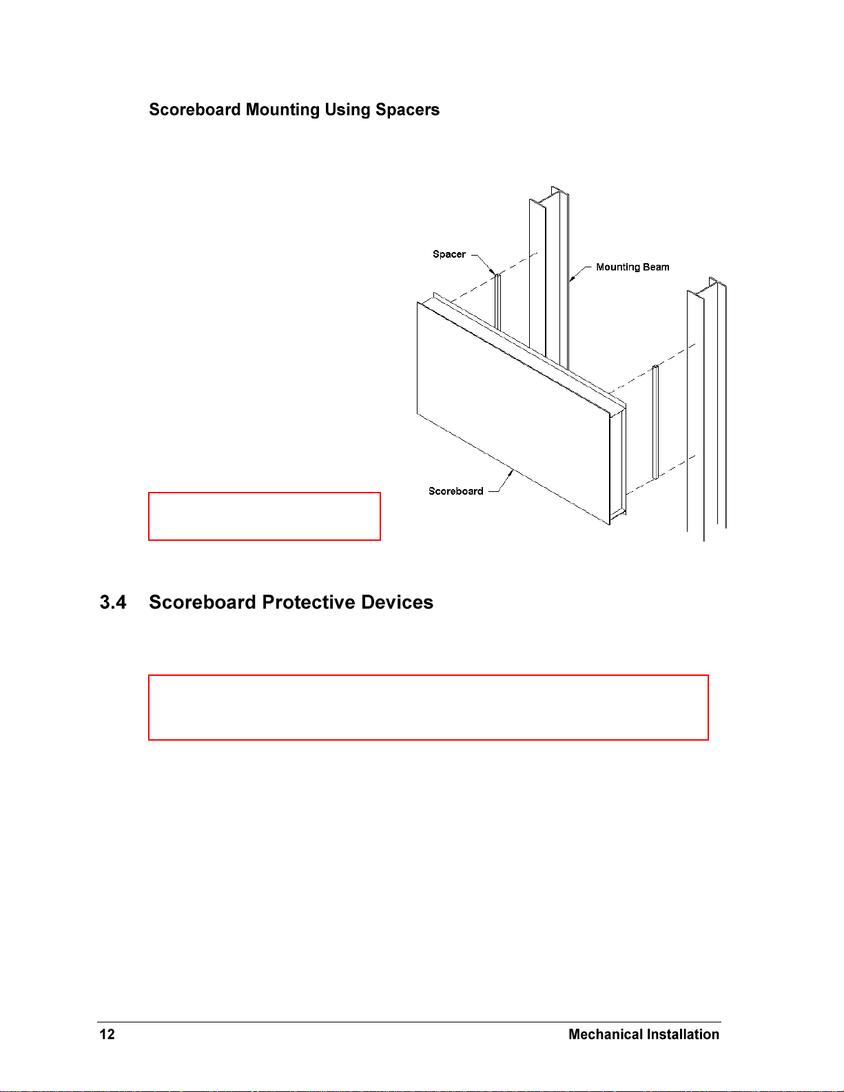
Figure 8: Mounting with Spacers
Note: Daktronics does not provide
these spacers.
Note: Some users install devices to protect the scoreboard from projectiles. Scoreboard
protection devices not provided by Daktronics must be approved by Daktronics prior to
installation. Failure to follow this approval procedure will void the scoreboard warranty.
Many customers add message centers or advertising panels to the top or bottom of their
scoreboards, and in some cases the depth of the add-on component may not match the depth
of the scoreboard. This will typically be scoreboards that are 8" deep.
To create a uniform appearance for the
overall display, Daktronics
recommends using spacers behind the
scoreboard so that the front face of the
display lines up evenly with the front
face of the added component. The
concept is illustrated in Figure 8.
During the installation, spacers are
placed between the mounting beams
and the back of the scoreboard cabinet.
Spacer size is determined by the height
and the extra depth required for the
front surface of the scoreboard to
match that of the optional message
center or ad panel.
Daktronics makes optional protective devices, including screens and netting, to help prevent
damage to the scoreboard due to normal ball impacts.
Page 17
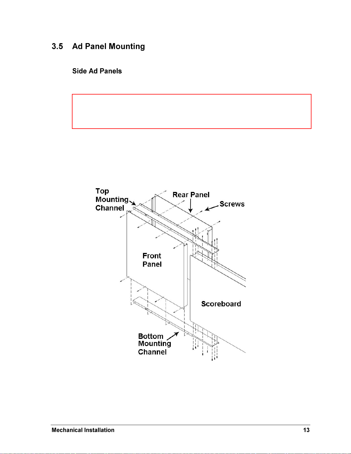
Figure 9: Side Ad Panel Mounting
Note: Be sure to attach any side ad panels to the scoreboard before mounting the display to
the support beams. Depending on the number of ad panels, the display may require a
different number and arrangement of beams. Refer to the installation specifications listed in
Section 3.1 and Appendix A.
Ad panels are designed to attach directly to either side of the scoreboard using mounting
channels (Figure 9).
1. Use the 8 screws (16 total) to secure both the top and bottom mounting channels off
of the appropriate side(s) of the scoreboard.
2. Attach both the front and rear panels to the mounting channels using the 16 screws.
3. After attaching the ad panels to the scoreboard, secure the scoreboard and/or ad
panels to the beams using the C-channel method shown in Figure 6 & Figure 7 of
Section 3.3.
Page 18
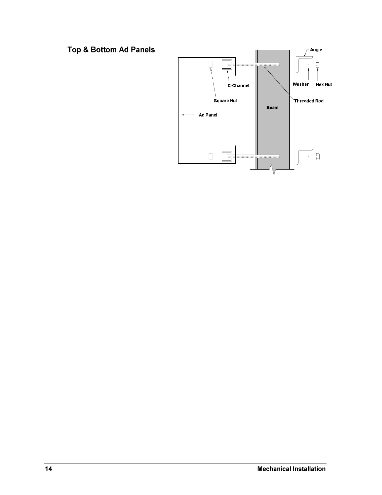
Figure 10: Top/Bottom Ad Panel Mounting
The installation uses C-channels,
clip angles, 1/2-13" threaded rods,
and 1/2" square nuts, hex nuts, and
lock washers similar to scoreboard
mounting shown in Section 3.3.
Mount the ad panel(s) as follows:
1. Use the width of the beam
to determine which hole
combination to use for the
bolts. Be sure to keep the
bolts as close to the beam as
possible.
2. Using the clip angle as a
template, use a 9/16" bit to
drill holes in the upper and
lower rear flange of the ad panel where the C-channel supports will be placed.
3. Position the C-channel inside the ad panel cabinet along the upper and lower rear
flanges as shown in Figure 10.
4. Place square nuts inside the channel and thread the long rods through both the C-
channel and the rear flange.
5. Lift the ad panel into position with the rods still in place.
6. With the threaded rod straddling the beams, place mounting angles over the ends of
each pair of bolts and secure with 1/2" lock washers and hex nuts.
7. Make final adjustments in the positioning of the ad panel.
8. Make sure that the threaded rods are perpendicular to the ad panel, and tighten all of
the 1/2" hex nuts.
Some ad panels have back sheets that must be removed before the display can be installed.
After marking and drilling holes in the upper and lower rear flanges of the ad panel, remove
the back sheets above and below the hole locations. Position the C-channel inside the cabinet
and attach the square nuts to the threaded rods as described above. Be sure to replace the
back sheets after placing the square nuts inside the channel and threading the rods through
the holes in both the upper and lower rear flanges.
Page 19
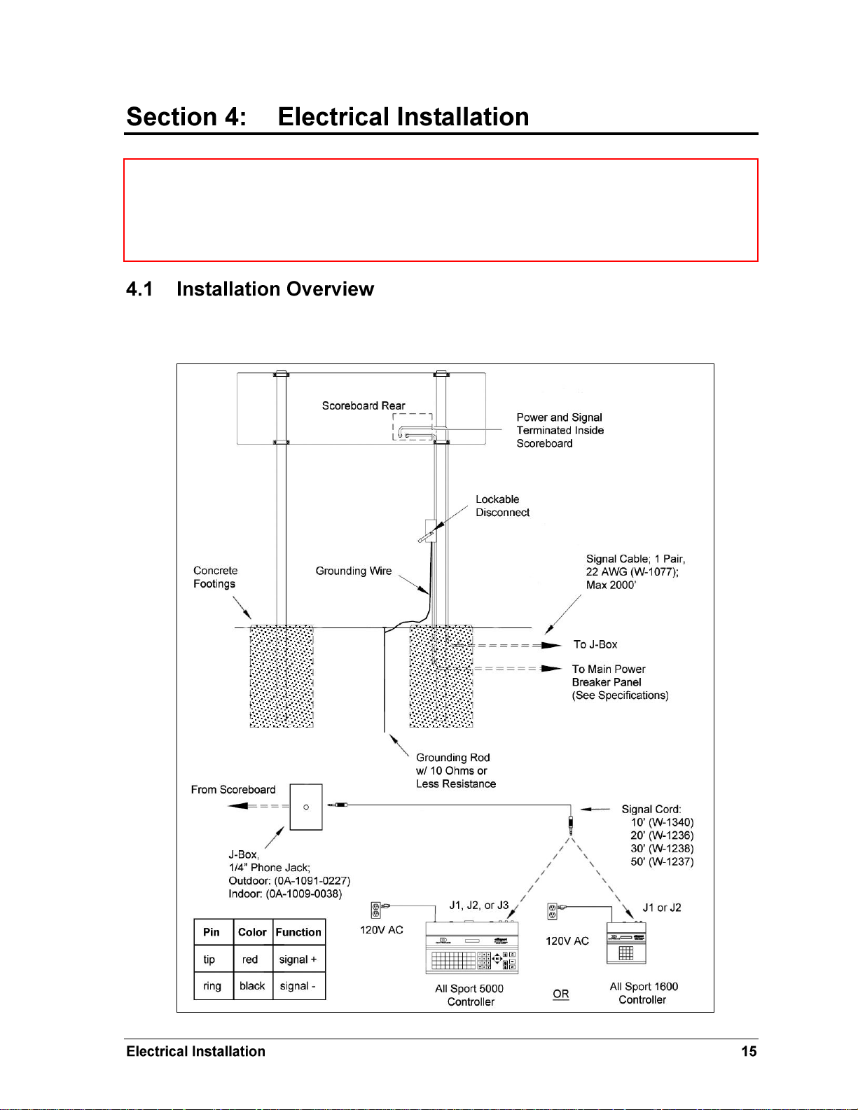
Figure 11: Wired Installation
CAUTION: Only qualified individuals should terminate power and signal cable and access the
electrical components of the display and its associated equipment. It is the responsibility of the
electrical contractor to ensure that all electrical work meets or exceeds local and national codes.
Daktronics engineering staff must approve all changes or the warranty will be void.
The diagram shown in Figure 11 illustrates a typical wired setup between a single-section
outdoor scoreboard and controller. Daktronics part numbers are shown in parentheses.
Page 20
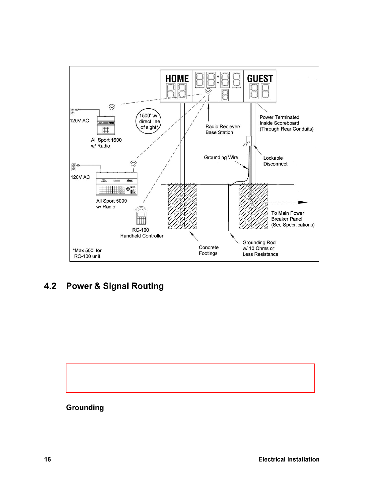
Figure 12: Wireless Installation
WARNING: It is critical that the scoreboard circuit be fused at 15 A and that all conductors
used must be designed to pass a 15 A current in normal operation. Failure to meet wiring
and overcurrent protection device requirements will void the scoreboard warranty.
The diagram shown in Figure 12 illustrates a typical wireless setup between a single-section
outdoor scoreboard and controller.
Correct power installation is imperative for proper display operation. The subsections that
follow give details of display power installation. Only qualified individuals should attempt to
complete the electrical installation; untrained personnel should not attempt to install these
displays or any of the electrical components. Improper installation could result in serious
damage to the equipment or injury to personnel.
Single-section outdoor scoreboards require a dedicated 120 V or 240 V circuit for incoming
power (refer to product specs in Section 2). The display itself has no breakers or fuses.
The display must be properly grounded according to local and national codes or the warranty
will be void. Proper grounding is necessary for reliable equipment operation and protects the
equipment from damaging destructive disturbances and lightning. Daktronics recommends a
resistance-to-ground of 10 ohms or less. The electrical contractor performing the electrical
Page 21

installation can verify ground resistance. Daktronics Sales and Service personnel can also
Figure 13: Conduit Knockouts
Figure 14: Power Warning Label
provide this service.
The display system must be earth-ground. The material for an earth-ground electrode differs
from region to region and may vary according to conditions present at the site. Consult local
and national electrical codes. The support structure of the display cannot be used as an earthground electrode.
There are two types of power installation: installation with ground and neutral conductors
provided, and installation with only a neutral conductor provided. These two power
installations differ slightly, as described in the following paragraphs:
Installation with Ground and Neutral Conductors Provided
For this type of installation, the power circuit must contain an isolated earth-ground
conductor. In this circumstance, do not connect neutral to ground at the disconnect or at the
display as this would violate electrical codes and void the warranty.
Use a disconnect so that all ungrounded lines can be disconnected. The National Electrical
Code requires the use of a lockable power disconnect within sight of or at the display.
Installation with Only a Neutral Conductor Provided
Installations where no grounding conductor is provided must comply with Article 250-32 of
the National Electrical Code. If the installation in question meets all of the requirements of
Article 250-32, the following guidelines must be observed:
Connect the grounding electrode cable at the local disconnect, never at the display
driver/power enclosure.
Use a disconnect that opens all of the ungrounded phase conductors.
Power and signal cables are routed into the
scoreboard from the rear through two
conduit knockouts (Figure 13). All power
and signal wiring terminates at the driver
enclosure. Note that systems with radio
control do not require external signal
wiring.
Look for a warning label similar to Figure
14 to locate the front access panel to the
driver enclosure. Open the access door or digit panel and
remove the metal cover to expose the enclosure (Figure 16).
To gain access to the termination connector, open the access
door and remove the cover from the enclosure. Refer to the
component locations drawings for access locations.
Page 22

Figure 15: Power/Signal
Terminal Block (TB1)
Figure 17: Driver Fiber
Connection Location
Figure 16: Driver Enclosure (16-column)
Connect the appropriate power and signal wires coming through the rear of the scoreboard to
the power terminal block (TB1), as shown in Figure 15. Refer to Drawings A-285469 and A-
285470 for a detailed layout of a 16- and 8-column driver enclosure, respectively.
TB1 has protection varistors across both “signal” terminals to the “ground” terminal. For
more information, refer to Drawings A-285892, A-286657, A-229706, and A-704861.
For signal cable, Daktronics recommends, as a minimum, single-pair, shielded cable, 22 AWG
(Daktronics part number W-1077). Two-pair shielded cable (W-1614) is preferred.
Another common signal communication method is fiber optic
cabling. A minimum cabling of multi-mode, 62.5/125 um, and 2core fiber cable is recommended (Daktronics part number is W-
1242). See Figure 17 for the location of the fiber connector on a 16or 8-column driver. This method requires a signal converter
between the All Sport console‟s scoreboard output and the fiber
optic cable (not provided by Daktronics).
Page 23

Figure 18: Digit Segment POST
Figure 19: Radio Settings during POST
Note: Scoreboards using the RC-100 controller will only display the channel settings.
The scoreboard performs a self-test each time that power is turned on and the control console
is powered off or not attached to the scoreboard. If the control console is attached and
powered on, the self-test does not run, and data from the control console is displayed on the
scoreboard after a brief period of time. Each scoreboard self-test pattern will vary depending
on the scoreboard model, the number of drivers and types of digits. Figure 18 shows an
example of the LED bar test pattern that each digit performs.
If a radio receiver is installed, the radio broadcast
settings (“b1”) and the channel settings (“c1”)
will be displayed in the Home and Guest or clock
digits (Figure 19) during the POST. These values
must match the settings in the control console
(refer to the appropriate control console manual
listed in Section 1.4).
The use of a disconnect near the scoreboard to completely cut all current-carrying lines
significantly protects the circuits against lightning damage. In order for this system to
provide protection, the power must be disconnected when the scoreboard is not in use.
The control console should also be disconnected from power and from the signal junction box
when the system is not in use. The same surges that may damage the scoreboard‟s driver can
also damage the console‟s circuitry.
Page 24

Page 25

Figure 20: LED Digit Panel
Note: If the panel is not held in place when the screws are removed, it could drop
immediately, possibly damaging LEDs or the digit harness.
IMPORTANT NOTES:
1. Disconnect power before doing any repair or maintenance work on the scoreboard!
2. Permit only qualified service personnel to access internal display electronics.
3. Disconnect power when not using the scoreboard.
For front-access scoreboards, all internal
electronic components and digits are
reached by opening an access door or a
digit panel on the front of the display.
Digit panels are held in place on the
scoreboard face by an offset flange across
the top and by screws at the bottom, as
shown in Figure 20.
To open an access panel:
1. Hold the digit panel in place by
putting hand pressure on it and
remove the screws.
2. Carefully lift the panel away from
the scoreboard, sliding it out and
down.
Refer to the following drawings to locate drivers, power, and signal components.
Reference Drawings:
Component Locations; BA-2515-31, G3LC ............................................ Drawing A-222583
Component Locations; BA-2715-31, G3LC ............................................ Drawing A-230119
Component Locations; BA-2718-31, G3LC ............................................ Drawing A-206050
Component Locations; BA-2618-31, G3LC ............................................ Drawing A-208073
Component Locations; SO-2918-31, G3LC ........................................... Drawing A-220840
Component Locations; MS-3918-31, G3LC ........................................... Drawing A-220350
Component Locations; FB-4005-31, G3LC ............................................ Drawing A-221249
Page 26

Figure 21: Digit Assembly
Note: This is a keyed connector and it will attach in
one way only. Do not attempt to force the connection.
LEDs are embedded in a circuit board that is
mounted to the back of the digit panel, as
shown in Figure 21. Do not attempt to remove
individual LEDs. In the case of a
malfunctioning LED or digit segment, replace
the entire digit circuit board.
To replace a digit circuit board:
1. Open the digit panel as described in
Section 5.1.
2. Disconnect the power/signal
connector from the back of the digit by
squeezing together the locking tabs
and pulling the connector free.
3. Use a
4. Position a new digit over the screws,
5. Tighten the nuts.
6. Reconnect the power/signal connector.
7. Close and secure the digit panel, then power up and test the scoreboard to see if
9
/32" nut driver to remove the
nuts securing the digits to the inside of
the panel, and then lift the digit off the
standoff screws.
making sure the rubber side of the
rubber-backed washer on the standoff
screws is facing the digit circuit board.
changing the digit has resolved the problem.
Scoreboards with 8-column drivers use a single transformer, while 16-column driver
enclosures require a dual transformer assembly.
To remove a transformer:
1. Open the access panel as described in Section 5.1.
2. Locate and disconnect all wires connected to the transformer (Figure 22).
3. Use a 9/32" nut driver to remove the hardware securing the transformer.
4. Fasten the new transformer in place and reconnect all wires.
Scoreboard Maintenance & Troubleshooting
Page 27

Figure 22: Driver Enclosure Location & Components
The access panel has
been removed to show
the driver enclosure.
Transformer
Power Terminal Block
16-column Driver
Location of Optional
Horn Switch Card
Reference Drawings:
Address Table, 1 Through 128 ............................................................... Drawing A-115078
Address Table 1; GEN IV Driver Address Dip Switch ............................ Drawing A-290261
The LED drivers perform the task of switching digits on and off within the scoreboard.
LED drivers are located inside of a driver enclosure. Refer to Figure 22 to view the location
and components of a driver enclosure, and refer to the Component Locations drawings in
Appendix A for the specific access location for each scoreboard model.
Most scoreboards use either 8- or 16-column drivers (Figure 23).
Page 28

LED
Color
Function
Operation
Summary
DS1
Green
Power
Steady on
DS1 will be on and steady to
indicate the driver has power.
DS2
Red
Signal RX
Steady on
or blinking
DS2 will be on or blinking when the
driver is receiving a signal and off
when there is no signal.
DS3
Amber
Status
Blinking
DS7 will be blinking at one second
intervals to indicate the driver is
running.
Figure 23: Driver Status Indicators
Driver Status Indicators
16-column Driver
8-column Driver
Note: While it is necessary to have the scoreboard powered on to check the LED indicators,
always disconnect scoreboard power before servicing.
When troubleshooting driver problems, three LEDs labeled DS1, DS2, and DS3 in Figure 23,
provide the following diagnostic information:
Note: While it is necessary to have the scoreboard powered on to check the LED indicators,
always disconnect scoreboard power before servicing.
Scoreboard Maintenance & Troubleshooting
Page 29

Each driver is enclosed with a transformer and signal terminal block. Drivers are typically
Figure 24: Driver Address Dip Switch
Note: It may be helpful to label the cables to know which cable goes to which
connector when reattaching the driver.
Note: The connectors are keyed and will attach in one way only. Do not attempt to
force the connections.
mounted inside the scoreboard and immediately behind a digit, but location and mounting
varies with the model of the scoreboard. Refer to Section 5.5 to locate the driver enclosure.
To replace a driver:
1. Open the digit panel or scoreboard face panel as described in Section 5.1.
2. Loosen the wing nuts to remove metal cover from the driver enclosure.
3. Disconnect all connectors from the driver by squeezing together the locking tabs and
pulling the connectors free.
Note: It may be helpful to label the cables to know which cable goes to which
connector when reattaching the driver.
4. Remove the screws or nuts securing the driver to the inside of the enclosure.
5. Carefully lift the driver from the display and place it on a clean, flat surface.
6. Position a new driver over the screws and tighten the nuts.
7. Reconnect all power/signal connectors.
Note: The connectors are keyed and will attach in one way only. Do not attempt to
force the connections.
8. Ensure the driver is set to the correct address (refer to Setting the Driver Address).
9. Close and secure the digit panel, then power up and test the scoreboard to see if
changing the driver has resolved the problem.
Since the same LED drivers can be used for many scoreboard models, each driver must be set
to receive the correct signal input, or address, for the model being used. Addresses are set
through the S1 dip switch on the driver (Figure 24) using a pen or small, pointed object.
Refer to the product specifications in Section 2 to determine the correct address setting of the
driver(s) in a particular scoreboard model and see Drawing A-290261 for addressing
information for driver addresses 1 – 128.
Another method of setting the driver address using the J19 address plug is available. This
address is set with jumper wires in a 12-pin plug which mates with a jack on the driver. Refer
to Drawing A-115078 for a listing of the wire/pin connections for driver addresses 1 – 128.
When using an address plug, it will not be possible to set the address with the S1 dip switch.
Page 30

Description
Daktronics Part No.
LED Indicator, BALL, STRIKE, OUT, H/E
0P-1192-0292
18" LED Digit
0P-1192-0291
8 Column Driver
0P-1192-0392
16 Column Driver
0P-1192-0384
Transformer
T-1066
15" LED Digit
0P-1192-0308
18" LED Ones Digit
0P-1192-0304
24" LED Horizontal Segment
0P-1192-0305
24" LED Vertical Segments
0P-1192-0306
Symptom/Condition
Possible Cause
Scoreboard will not light
Console not connected or poor connection
No power to control console
No power to the scoreboard
Garbled display
Internal driver logic malfunction
Control console malfunction
Digit will not light
Black wire to digit broken
Poor contact at driver connection.
Driver malfunction
Segment will not light
Broken LED or connection
Driver shift register failure
Broken wire between driver and digit
Poor contact at driver connector
Segment stays lit
Driver shift register failure
Short circuit on digit
Data appears in the wrong
place on the scoreboard
Incorrect address settings on drivers (consult
tables and set correct addresses)
Refer to the following table for Daktronics scoreboard replacement parts.
This section lists some of the more common problems with the scoreboard and indicates
possible causes and/or corrective actions.
Scoreboard Maintenance & Troubleshooting
Page 31

Schools (primary through community/junior colleges),
religious organizations, municipal clubs and community
centers
877-605-1115
Universities and professional sporting events, live events
for auditoriums and arenas
866-343-6018
To serve customers‟ repair and maintenance needs, Daktronics offers both an Exchange
Program and a Repair & Return Program.
Daktronics unique Exchange Program is a quick service for replacing key parts in need of
repair. If a part requires repair or replacement, Daktronics sends the customer a replacement,
and the customer sends the defective part to Daktronics. This decreases display downtime.
Identify these important numbers:
Display Serial Number: _________________________________________________________
Display Model Number: _________________________________________________________
Contract Number: ______________________________________________________________
Date Installed: _________________________________________________________________
Daktronics Customer ID Number: ________________________________________________
To participate in the Exchange Program, follow these steps.
1. Call Daktronics Customer Service.
2. When the new exchange part is received, mail the old part to Daktronics.
3. If the replacement part fixes the problem, send in the problem part which is being
replaced.
a. Package the old part in the same shipping materials in which the replacement
part arrived.
b. Fill out and attach the enclosed UPS shipping document.
c. Ship the part to Daktronics.
4. A charge will be made for the replacement part immediately, unless a qualifying
service agreement is in place. In most circumstances, the replacement part will be
invoiced at the time it is shipped.
5. If the replacement part does not solve the problem, return the part within 30 working
days or the full purchase price will be charged.
Page 32

If, after the exchange is made the equipment is still defective, please contact Customer Service
immediately. Daktronics expects immediate return of an exchange part if it does not solve the
problem. The company also reserves the right to refuse parts that have been damaged due to
acts of nature or causes other than normal wear and tear.
For items not subject to exchange, Daktronics offers a Repair & Return Program. To send a
part for repair, follow these steps:
1. Call or fax Daktronics Customer Service:
Refer to the appropriate market number in the chart listed on the
previous page.
2. Receive a Return Materials Authorization (RMA) number before shipping.
This expedites repair of the part.
3. Package and pad the item carefully to prevent damage during shipment.
Electronic components, such as printed circuit boards, should be placed in an
antistatic bag before boxing. Daktronics does not recommend using packing „peanuts‟
when shipping.
4. Enclose:
name
address
phone number
the RMA number
a clear description of symptoms
Daktronics Customer Service
RMA #
201 Daktronics Drive, Dock E
Brookings, SD 57006
Fax: 605-697-4444
The Daktronics Warranty and Limitation of Liability is located in Appendix B. The Warranty
is independent of Extended Service agreements and is the authority in matters of service,
repair, and display operation.
Scoreboard Maintenance & Troubleshooting
Page 33

Figure 25: Changing Scoreboard Captions
CAUTION: The aluminum caption changer can conduct electricity. Do not use it within 20feet of power lines.
Also be careful when using the caption changer in high or gusting winds. Wind may catch
the panel and unhook it from the changer or make it difficult to maintain a grip on the pole.
Hold the pole tightly in windy conditions.
Team name caption kits contain
hardware for one caption only and
consist of an upper caption retainer,
a lower caption retainer, a
changeable caption panel and
screws. The standard HOME and
GUEST captions are applied directly
to the face of the scoreboard. Team
name captions are on changeable
panels that fit into retainers
mounted above and below the
HOME and GUEST captions. If these
retainers are not already present,
attach the retainers included with
the caption kit.
To install a changeable panel:
1. Insert the screws on the caption changing pole into the keyholes on the panel.
2. Lift the panel all the way up into the upper retainer and then insert the bottom of the
panel into the lower retainer (Figure 25).
3. Take the screws on the caption changing pole out of the keyholes.
Reverse this procedure to remove the caption panel.
The caption changer pole is extendable. Loosen the ring tightener and extend the pole to the
desired length, and then tighten the ring before lifting the caption.
Page 34

Radio control is an option for all Daktronics outdoor LED scoreboards. The system provides
scoreboard control via a 2.4 GHz, extra-high frequency FM signal.
The radio transmitter and receiver are not standard. This setup requires a control console
equipped with radio output as well as a radio receiver plugged into the power terminal block
in the driver/power enclosure and mounted internally to the front panel of the scoreboard.
For additional information about this option, contact a Daktronics representative; for
complete information on setting up radio communication control, refer to the Gen V Radio
Installation Manual (ED-13831).
Certain smaller scoreboards also have the option of using a hand-held RC-100 wireless radio
controller, which requires a radio base station installed in the scoreboard cabinet. For more
information refer to the Remote Control System RC-100 Operational Overview (ED-15133).
Both manuals are available online at www.daktronics.com/manuals.
The portable power pack permits operation of a scoreboard via battery power. The power
pack is self-contained and mounted on a wheeled cart and includes batteries, a charger, and a
120 V AC power inverter. For additional information about the power pack kit (Daktronics
part number 0A-1192-0360), contact a Daktronics representative. For a list of compatible
scoreboard models and battery operation times, refer to SL-05070.
Scoreboard Options
Page 35

Appendix A: Reference Drawings
Address Table, 1 Through 128 .................................................................................. Drawing A-115078
Component Locations; BA-2718-31, G3LC ............................................................... Drawing A-206050
Installation Specifications; 5'x10' DistaView .............................................................. Drawing A-206385
1 side ad panel .................................................................................................... Drawing A-206433
2 side ad panel .................................................................................................... Drawing A-206437
Component Locations; BA-2618-31, G3LC ............................................................... Drawing A-208073
Component Locations; MS-3918-31, G3LC............................................................... Drawing A-220350
Component Locations; SO-2918-31, G3LC ............................................................... Drawing A-220840
Component Locations; FB-4005-31, G3LC ............................................................... Drawing A-221249
Component Locations; BA-2515-31, G3LC ............................................................... Drawing A-222583
Installation Specifications; 3'x6' DistaView ................................................................ Drawing A-222869
1 side ad panel .................................................................................................... Drawing A-222872
2 side ad panel .................................................................................................... Drawing A-222875
Schematic; DistaView OD LED Multi-driver Display .................................................. Drawing A-229706
Installation Specifications; BA-2715-31 ..................................................................... Drawing A-229969
1 side ad panel .................................................................................................... Drawing A-229970
Component Locations; BA-2715-31, G3LC ............................................................... Drawing A-230119
Driver; GEN IV LC Outdoor LED, 16 Col ................................................................... Drawing A-285469
Driver; GEN IV LC Outdoor LED, 8 Col ..................................................................... Drawing A-285470
Schematic; XFMR 8 Col, GEN IV, DistaView LED .................................................... Drawing A-285892
Schematic; XFMR 16 Col, GEN IV, DistaView LED .................................................. Drawing A-286657
Address Table 1; GEN IV Driver Address Dip Switch ................................................ Drawing A-290261
Schem.240V (LC) XFMR 16 Col GEN IV Outdoor Driver .......................................... Drawing A-704861
Page 36

Page 37

Page 38

Page 39

Page 40

Page 41

Page 42

Page 43

Page 44

Page 45

Page 46

Page 47

Page 48

Page 49

Page 50

Page 51

Page 52

Page 53

Page 54

Page 55

Page 56

Page 57

Page 58

Page 59

Page 60

Page 61

Appendix B: Daktronics Warranty and Limitation
of Liability
Page 62

Page 63

Copyright © Daktronics, Inc. SL-02374 Rev 10 02-Mar-2009 Page 1 of 2
DAKTRONICS
WARRANTY AND LIMITATION OF LIABILITY
This Warranty and Limitation of Liability (the “Warranty”) sets forth the warranty provided by Daktronics with respect to the Equipment. By accepting
delivery of the Equipment, Purchaser agrees to be bound by and accept these terms and conditions. All defined terms within the Warranty shall have the
same meaning and definition as provided elsewhere in the Agreement.
DAKTRONICS WILL ONLY BE OBLIGATED TO HONOR THE WARRANTY SET FORTH IN THESE TERMS AND CONDITIONS UPON RECEIPT OF FULL
PAYMENT FOR THE EQUIPMENT.
1. Warranty Coverage
2. Exclusion from Warranty Coverage
A. Daktronics warrants to the original end-user that the Equipment will be free from Defects (as defined below) in materials and
workmanship for a period of one (1) year (the “Warranty Period”). The warranty period shall commence on the earlier of: (i) four weeks from
the date that the equipment leaves Daktronics’ facility; or (ii) Substantial Completion as defined herein. The warranty period shall expire on the
first anniversary of the commencement date.
“Substantial Completion” means the operational availability of the Equipment to the Purchaser in accordance with the Equipment’s
specifications, without regard to punch-list items, or other non-substantial items which do not affect the operation of the Equipment.
B. Daktronics’ obligation under this Warranty is limited to, at Daktronics’ option, replacing or repairing, any Equipment or part thereof that is
found by Daktronics not to conform to the Equipment’s specifications. Unless otherwise directed by Daktronics, any defective part or
component shall be returned to Daktronics for repair or replacement. Daktronics may, at its option, provide on-site warranty service.
Daktronics shall have a reasonable period of time to make such replacements or repairs and all labor associated therewith shall be performed
during regular working hours. Regular working hours are Monday through Friday between 8:00 a.m. and 5:00 p.m. at the location where
labor is performed, excluding any holidays observed by either Purchaser or Daktronics.
C. Daktronics shall pay ground transportation charges for the return of any defective component of the Equipment. If returned Equipment is
repaired or replaced under the terms of this warranty, Daktronics will prepay ground transportation charges back to Purchaser; otherwise,
Purchaser shall pay transportation charges to return the Equipment back to the Purchaser. All returns must be pre-approved by Daktronics
before shipment. Daktronics shall not be obligated to pay freight for any unapproved return. Purchaser shall pay any upgraded or expedited
transportation charges.
D. Any replacement parts or Equipment will be new or serviceably used, comparable in function and performance to the original part or
Equipment, and warranted for the remainder of the Warranty Period. Purchasing additional parts or Equipment from the Seller does not
extend this Warranty Period.
E. Defects shall be defined as follows. With regard to the Equipment (excepting LEDs), a “Defect” shall refer to a material variance from the
design specifications that prohibit the Equipment from operating for its intended use. With respect to LEDs, “Defects” are defined as LED pixels
that cease to emit light. The limited warranty provided by Daktronics does not impose any duty or liability upon Daktronics for partial LED
pixel degradation. Nor does the limited warranty provide for the replacement or installation of communication methods including but not
limited to, wire, fiber optic cable, conduit, trenching, or for the purpose of overcoming local site interference radio equipment substitutions.
THIS LIMITED WARRANTY IS THE ONLY WARRANTY APPLICABLE TO THE EQUIPMENT AND REPLACES ALL OTHER WARRANTIES OR
CONDITIONS, EXPRESS OR IMPLIED, INCLUDING, BUT NOT LIMITED TO, THE IMPLIED WARRANTIES OR CONDITIONS OF
MERCHANTABILITY AND FINTESS FOR A PARTICULAR PURPOSE. SPECIFICALLY, EXCEPT AS PROVIDED HEREIN, THE SELLER UNDERTAKES
NO RESPONSIBILITY FOR THE QUALITY OF THE EQUIPMENT OR THAT THE EQUIPMENT WILL BE FIT FOR ANY PARTICULAR PURPOSE FOR
WHICH PURCHASER MAY BE BUYING THE EQUIPMENT. ANY IMPLIED WARRANTY IS LIMITED IN DURATION TO THE WARRANTY PERIOD.
NO ORAL OR WRITTEN INFORMATION, OR ADVICE GIVEN BY THE COMPANY, ITS AGENTS OR EMPLOYEES, SHALL CREATE A WARRANTY
OR IN ANY WAY INCREASE THE SCOPE OF THIS LIMITED WARRANTY.
THIS LIMITED WARRANTY IS NOT TRANSFERABLE.
The limited warranty provided by Daktronics does not impose any duty or liability upon Daktronics for:
A Any damage occurring, at any time, during shipment of Equipment unless otherwise provided for in the Agreement. When returning
Equipment to Daktronics for repair or replacement, Purchaser assumes all risk of loss or damage, and agrees to use any shipping containers
that might be provided by Daktronics and to ship the Equipment in the manner prescribed by Daktronics;
B. Any damage caused by the unauthorized adjustment, repair or service of the Equipment by anyone other than personnel of Daktronics or
its authorized repair agents;
C. Damage caused by the failure to provide a continuously suitable environment, including, but not limited to: (i) neglect or misuse, (ii) a
failure or sudden surge of electrical power, (iii) improper air conditioning or humidity control, or (iv) any other cause other than ordinary use;
Page 64

Copyright © Daktronics, Inc. SL-02374 Rev 10 02-Mar-2009 Page 2 of 2
D. Damage caused by fire, flood, earthquake, water, wind, lightning or other natural disaster, strike, inability to obtain materials or utilities,
war, terrorism, civil disturbance or any other cause beyond Daktronics’ reasonable control;
E. Failure to adjust, repair or replace any item of Equipment if it would be impractical for Daktronics personnel to do so because of
connection of the Equipment by mechanical or electrical means to another device not supplied by Daktronics, or the existence of general
environmental conditions at the site that pose a danger to Daktronics personnel;
F. Any statements made about the product by salesmen, dealers, distributors or agents, unless such statements are in a written document
signed by an officer of Daktronics. Such statements as are not included in a signed writing do not constitute warranties, shall not be relied
upon by Purchaser and are not part of the contract of sale;
G. Any damage arising from the use of Daktronics products in any application other than the commercial and industrial applications for
which they are intended, unless, upon request, such use is specifically approved in writing by Daktronics; or
H. Any performance of preventive maintenance.
3. Limitation of Liability
4. Assignment of Rights
5. Dispute Resolution
6. Governing Law
7. Availability of Extended Service Agreement
Daktronics shall be under no obligation to furnish continued service under this Warranty if alterations are made to the Equipment without the
prior written approval of Daktronics.
It is specifically agreed that the price of the Equipment is based upon the following limitation of liability. In no event shall Daktronics (including
its subsidiaries, affiliates, officers, directors, employees, or agents) be liable for any special, consequential, incidental or exemplary damages
arising out of or in any way connected with the Equipment or otherwise, including but not limited to damages for lost profits, cost of substitute
or replacement equipment, down time, lost data, injury to property or any damages or sums paid by Purchaser to third parties, even if
Daktronics has been advised of the possibility of such damages. The foregoing limitation of liability shall apply whether any claim is based
upon principles of contract, tort or statutory duty, principles of indemnity or contribution, or otherwise.
In no event shall Daktronics be liable to Purchaser or any other party for loss, damage, or injury of any kind or nature arising out of or in
connection with this Warranty in excess of the purchase price of the Equipment actually delivered to and paid for by the Purchaser. The
Purchaser’s remedy in any dispute under this Warranty shall be ultimately limited to the Purchase Price of the Equipment to the extent the
Purchase Price has been paid.
The Warranty contained herein extends only to the original end-user (which may be the Purchaser) of the Equipment and no attempt to extend
the Warranty to any subsequent user-transferee of the Equipment shall be valid or enforceable without the express written consent of
Daktronics.
Any dispute between the parties will be resolved exclusively and finally by arbitration administered by the American Arbitration Association
(“AAA”) and conducted under its rules, except as otherwise provided below. The arbitration will be conducted before a single arbitrator. The
arbitration shall be held in Brookings, South Dakota. Any decision rendered in such arbitration proceedings will be final and binding on each
of the parties, and judgment may be entered thereon in any court of competent jurisdiction. This arbitration agreement is made pursuant to a
transaction involving interstate commerce, and shall be governed by the Federal Arbitration Act.
The rights and obligations of the parties under this warranty shall not be governed by the provisions of the United Nations Convention on
Contracts for the International Sales of Goods of 1980. Both parties consent to the application of the laws of the State of South Dakota to
govern, interpret, and enforce all of Purchaser and Daktronics rights, duties, and obligations arising from, or relating in any manner to, the
subject matter of this Warranty, without regard to conflict of law principles.
For Purchaser’s protection, in addition to that afforded by the warranties set forth herein, Purchaser may purchase extended warranty services
to cover the Equipment. The Extended Service Agreement, available from Daktronics, provides for electronic parts repair and/or on-site labor
for an extended period from the date of expiration of this warranty. Alternatively, an Extended Service Agreement may be purchased in
conjunction with this warranty for extended additional services. For further information, contact Daktronics Customer Service at 1-877-605-
1116.
 Loading...