

Page 1
Multi-Section Outdoor
LED Scoreboards
Installation, Maintenance,
and Specifications Manual
All Sport® is a registered trademark of Daktronics, Inc.
National Electrical Code
BA-1518-11 FB-1424-11 FB-1630-11 FB-2001-11 SO-1424-11
BA-1524-11 FB-1430-11 FB-1630L-11 FB-2002-11 SO-1624-11
BA-2007-11 FB-1524-11 FB-1730-11 FB-2003-11 SO-1830-11
BA-3718-11 FB-1530-11 FB-1830-11 MS-2009-11 SO-1830L-11
BA-3724-11 FB-1624-11 FB-1830L-11 MS-2118-11 SO-1930-11
®
is a registered trademark of NFPA International.
Scoreboard Models
ED12562
Product 1192
Rev 4 – 28 October 2002
Copyright ã 2002 Daktronics, Inc.
All rights reserved. While every precaution has been taken
in the preparation of this manual, the publisher assumes no
responsibility for errors or omissions. No part of this book covered
by the copyrights hereon may be reproduced or copied in any form
or by any means – graphic, electronic, or mechanical, including
photocopying, taping, or information storage and retrieval
systems – without written permission of the publisher.
Note: Please fill in the information below for your
display, and use it as a reference when calling
Daktronics for assistance.
Scoreboard Serial No. _________________
Scoreboard Model No. _________________
Date Installed ________________________
PO Box 5128 331 32nd Ave Brookings SD 57006
Tel 605-697-4036 or 877-605-1115 Fax 605-697-4444
www.daktronics.com e-mail: helpdesk@daktronics.com
ED12562
Page 2

Page 3

Table of Contents
Section 1: Introduction............................................................................................... 1-1
1.1 How To Use This Manual ..........................................................................................1-1
1.2 Daktronics Nomenclature...........................................................................................1-2
1.3 Manual Overview.......................................................................................................1-3
1.4 Product Overview....................................................................................................... 1-3
1.5 Model Names .............................................................................................................1-4
1.6 Product Safety Approval ............................................................................................ 1-4
Section 2: Model Identification .................................................................................. 2-1
Section 3: Specifications............................................................................................ 3-1
3.1 Multi-Section Scoreboards......................................................................................... 3-2
Section 4: Component Locations .............................................................................. 4-1
Section 5: Schematics................................................................................................ 5-1
Section 6: Mechanical Installation............................................................................. 6-1
6.1 Scoreboard Protective Devices ..................................................................................6-1
6.2 Footings and Beams ................................................................................................... 6-1
6.3 Lifting the Scoreboard................................................................................................6-4
6.4 Scoreboard Mounting.................................................................................................6-5
6.5 Ad Panel Mounting .................................................................................................... 6-6
6.6 Optional One- or Two-Line Message Center Mounting............................................ 6-6
Section 7: Electrical Installation ................................................................................ 7-1
7.1 Power Requirements ..................................................................................................7-1
Grounding ............................................................................................................ 7-2
Power Installation ................................................................................................ 7-2
7.2 Power and Signal Connection .................................................................................... 7-3
Connections Between Sections............................................................................ 7-3
Interconnect Panel Connections ..........................................................................7-4
Section 8: Scoreboard Maintenance and Troubleshooting ..................................... 8-1
8.1 Cabinet Specifications................................................................................................ 8-1
8.2 Component Location and Access...............................................................................8-1
Replacing a Digit .................................................................................................8-2
Replacing a Digit Segment ..................................................................................8-2
Replacing a Breakout Board................................................................................8-3
Replacing a Driver...............................................................................................8-3
8.3 Schematic ................................................................................................................... 8-4
Table of Contents i
Page 4

LED Drivers............................................................................................................... 8-4
8.4
8.5 Segmentation and Digit Designation......................................................................... 8-4
8.6 Power-On Self-Test ................................................................................................... 8-5
8.7 Lightning Protection .................................................................................................. 8-5
8.8 Troubleshooting......................................................................................................... 8-5
8.9 Replacement Parts ..................................................................................................... 8-7
8.10 Daktronics Exchange and Repair and Return Programs............................................ 8-7
Section 9: Team Name Message Center Maintenance.............................................9-1
9.1 Team Name Message Center System Overview........................................................ 9-1
9.2 Maintenance and Troubleshooting Overview............................................................ 9-1
9.3 Signal Summary......................................................................................................... 9-2
9.4 Power Summary......................................................................................................... 9-2
9.5 Service and Diagnostics............................................................................................. 9-2
TNMC Current Loop Interface Card................................................................... 9-3
TNMC Controller................................................................................................ 9-4
Modules and Drivers........................................................................................... 9-6
Power Supplies.................................................................................................... 9-7
Weatherstripping................................................................................................. 9-7
9.6 TNMC Display Maintenance..................................................................................... 9-8
9.7 Troubleshooting......................................................................................................... 9-8
9.8 Initialization Information at Startup .......................................................................... 9-9
9.9 Replacement Parts List .............................................................................................. 9-9
9.10 TNMC Exchange and Repair and Return Programs................................................ 9-10
Section 10: Scoreboard Options ................................................................................10-1
10.1 Football Scoreboard Accessories............................................................................. 10-1
10.2 Captions for Other Sports ........................................................................................ 10-1
Installing and Changing Captions ..................................................................... 10-1
10.3 Trumpet Horn .......................................................................................................... 10-2
120 V Trumpet Horn Installation (Internally Mounted)................................... 10-2
DC Trumpet Horn Installation (Externally Mounted) ...................................... 10-3
10.4 Radio Control........................................................................................................... 10-4
Appendix A: Reference Drawings................................................................................... A-1
Appendix B: Eyebolts..................................................................................................... B-1
ii Table of Contents
Page 5
Section 1: Introduction
1.1 How To Use This Manual
This manual explains the installation of Daktronics Outdoor LED Timing Displays and provides
details for display maintenance. For other questions regarding the safety, installation, operation, or
service of these systems, contact Daktronics. Customer Service Help Desk telephone numbers are
listed on the cover page of this manual. This manual would be referred to as ED12562.
Important Safeguards:
1. Read and understand these instructions before installing the display.
2. Do not drop the control console or allow it to get wet.
3. Properly ground the timer with a grounding electrode at the display location.
4. Disconnect power when the display is not in use.
5. Disconnect power when servicing the display.
6. Do not modify the structure or attach any panels or coverings to the display without the
express written consent of Daktronics, Inc.
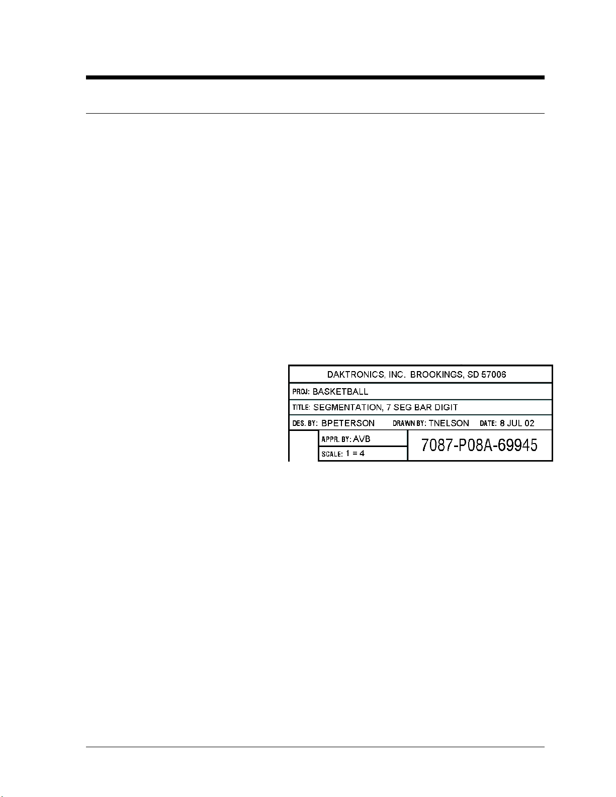
The box at right illustrates the Daktronics drawing numbering system. Daktronics identifies
individual engineering drawings by the
drawing number (7087-P08A-69945 in
the example), which is located in the
lower right corner of the drawing. This
manual refers to drawings by their last set
of digits and the letter preceding them.
The example would be Drawing A-
69945.
Reference drawings are grouped and
inserted in alphanumeric order in the
Appendix.
Listed below are a number of drawing types commonly used by Daktronics, along with the
information that each is likely to provide.
+
System Riser Diagrams: overall system layout from control room to display, power, and phase
requirements.
+
Shop Drawings: fan locations, transformer locations, mounting information, power and signal
entrance points, and access method (front or rear).
+
Schematics: power wiring, signal wiring, panelboard or power termination panel assignments,
signal termination panel assignments, and transformer assignments.
+
Final Assembly: component locations, part numbers, display dimensions, and
assembly/disassembly instructions.
Figure 1: Daktronics Drawing Label
Introduction 1-1
Page 6
All references to drawing numbers, appendices, figures, or other manuals are presented in bold
typeface, as in this example: “Refer to Drawing A-114667 for the location of the driver
enclosure.” Additionally, any drawings referenced within a particular subsection are listed at the
beginning of that subsection in the following manner:
Reference Drawing:
Shop Drawing; 16 High 2 ½" Small Matrix ................................... Drawing A-114667
Daktronics identifies each manual by assigning an engineering document, or ED, number, which is
located on the cover page. This manual, for example, would be referred to as ED13313.
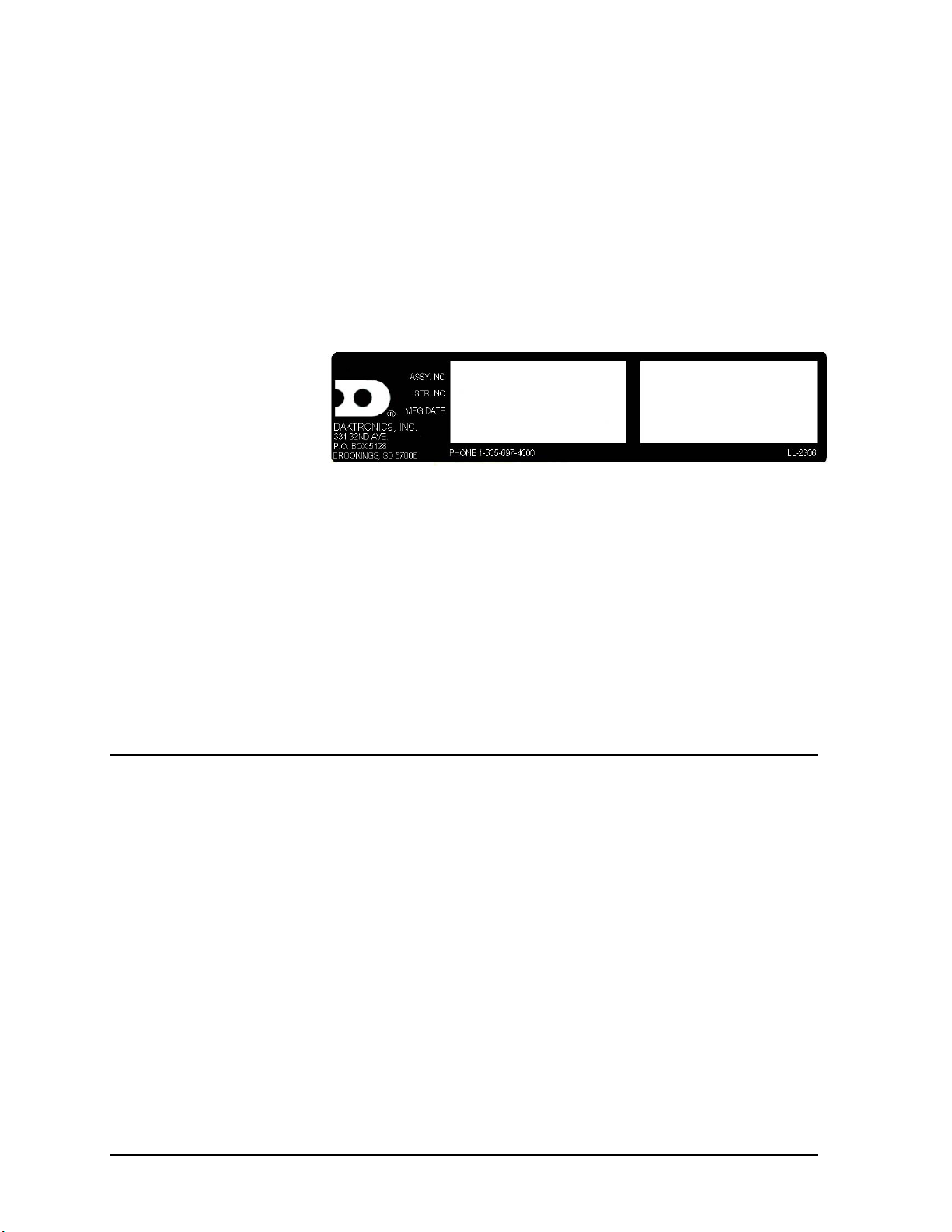
The serial and model numbers of a Daktronics scoreboard can be found on the ID label on the display.
The label will be similar to
the one shown in Figure 2.
When calling Daktronics
Customer Service, please
have this information
available to ensure that
your request is serviced
as quickly as possible. For
Figure 2: Scoreboard Label
future reference, note your scoreboard model number, serial number, and installation date on the front
page of this manual.
Daktronics displays are built for long life and require little maintenance. However, from time to time,
certain display components will have to be replaced. The Replacement Parts List in Section 4
provides names and part numbers of components that may require replacement during the life of this
display.
Following the Replacement Parts List is an explanation of Daktronics exchange and replacement
programs. Refer to these instructions if you must replace or repair any display component.
1.2 Daktronics Nomenclature
To fully understand some Daktronics drawings, such as schematics, it is necessary to know how
various components are labeled in those drawings. You will find this information useful when trying
to communicate maintenance or troubleshooting efforts.
The label "A" on a drawing item typically denotes an assembly. An assembly can be a single circuit
board or a collection of components that function together, usually mounted on a single plate or in a
single enclosure.
In addition, the following labeling formats might be found on various Daktronics drawings:
+
"TB_ _" denotes a termination block for power or signal cable.
+
"F_ _" denotes a fuse.
+
"E_ _" denotes a grounding point.
+
"J_ _" denotes a power or signal jack.
+
"P_ _" denotes a power or signal plug for the opposite jack.
1-2 Introduction
Page 7

Finally, Daktronics part numbers are commonly listed on drawings. Those part numbers can be used
when requesting replacement parts from Daktronics Customer Service. Take note of the following
part number formats. (Not all possible formats are listed here.)
+
"0P-_ _ _ _-_ _ _ _" denotes an individual circuit board, such as a driver board.
+
"0A-_ _ _ _-_ _ _ _" denotes an assembly, such as a circuit board and the plate or bracket to
which it is mounted. A collection of circuit boards working as a single unit may also carry an
assembly label.
+
"W-_ _ _ _" denotes a wire or cable. Cables may also carry the assembly numbering format in
certain circumstances. This is especially true of ribbon cables.
+
"F-_ _ _ _" denotes a fuse.
+
"T-_ _ _ _" denotes a transformer.
+
"PR-_ _ _ _ _ -_" denotes a specially ordered part.
+
"M-_ _ " denotes a metal part, and "0M_ _ _ _ _ _" typically denotes a fabricated metal
assembly.
1.3 Manual Overview
This manual details outdoor LED timing displays with numeric digits. It is divided into the following
sections:
Section 1: Provides an overview of the product, product safety information, labeling and
Section 2: Contains a list of drawings to be used in model identification.
Section 3: Contains specifications for scoreboard models listed in this manual.
Section 4: Contains a list of drawings listing component locations.
Section 5: Lists specific schematic drawings for each scoreboard model.
Section 6: Contains information regarding mechanical installation.
Section 7: Contains information pertaining to electrical installation.
Section 8: Provides details concerning scoreboard maintenance and troubleshooting.
Section 9: Provides information for team name message center maintenance.
Section 10: Lists optional scoreboard features.
Appendix A: Contains all engineering drawings referenced in the manual.
Appendix B: Contains information about eyebolts and scoreboard lifting.
The various sections in this manual contain model-specific information, including dimensions, digit
configuration, and power requirements. The scoreboard engineering drawings, located in Appendix A,
also list dimensions, weight, and mounting instructions for each display. Additionally, the model
number and electrical requirements can be found on a label on the display entrance panel.
numbering descriptions.
1.4 Product Overview
Daktronics outdoor LED scoreboards are part of a family of scoring and timing displays designed to
offer easy installation, readability and reliability. Microprocessor control assures consistent operation
and accuracy.
Introduction 1-3
Page 8

Featuring large, highly visible digits 15, 18, 24, and 30" tall, the boards use light-emitting diodes to
power the scoreboard display. (Light-emitting diodes, or LEDs, are tiny, solid-state lighting units.
They are low-energy, high intensity lighting components.) Scoreboards in this series use red-orange
LEDs for maximum outdoor visibility.
Because of their LED technology, the scoreboards consume little power. Power usage in this series
ranges from little more than a household lamp.
The scoreboards in this series are modular in construction, typically with a top and a bottom section,
but some with as many as four different sections. The units are shipped separately and joined at
installation. Unpowered sections, connected to the internal power and signal panels with cabling, are
referred to as slave sections, while those housing the electronic control components are masters.
Cabinets for the displays are of heavy-gauge aluminum construction. Mounting weights and
dimensions for each model are listed in Section 3 of this manual.
KNote: Some drawings and text in this manual refer to team name message centers, or TNMCs.
Team name message centers are scoreboard-mounted matrix LED units which electronically display
home and guest team names. TNMCs are available as a standard new scoreboard option with many of
the models in this series, and the message centers are also available for retrofit on existing
scoreboards. With some TNMC systems still in development, additional models will be added to
subsequent editions of this manual. Section 10 of this manual offers step-by-step information of
TNMC maintenance and troubleshooting.
1.5 Model Names
Daktronics scoreboards are differentiated by their model numbers: FB-1624, for example, designates
a specific football scoreboard. The two-letter prefixes for scoreboards in this manual include the
following: BA- baseball; FB-football; MS-multi-sport, and SO-soccer.
In the outdoor LED scoreboard series, the three or four numbers following the prefix typically
identify a specific model.
Most Daktronics scoreboards also carry a two-number suffix that refers to indoor-outdoor status and
power supply: -9 and -10 are indoor displays, 120 V and 230 V respectively; and -11 and -12 are
outdoor scoreboards, 120 V and 230 V. All of the LED displays in this manual carry the -11 suffix,
signifying that they have been designed and manufactured for outdoor use and have a 120 V AC
power requirement.
1.6 Product Safety Approval
Daktronics outdoor scoreboards and timing displays are ETL listed, tested to CSA standards and CE
labeled for outdoor use. Contact Daktronics with any questions regarding testing procedures
1-4 Introduction
Page 9

Section 2: Model Identification
Use the following drawings to determine the scoreboard model number. The drawings are listed here
in alphabetical order by scoreboard model line, and they are inserted in the Appendix in
alphanumeric order. Individual scoreboard drawings are also grouped in the Appendix.
Reference Drawing:
Multi-Section Baseball Scoreboards .............................................. Drawing A-126086
Multi-Section Baseball Scoreboards, w/TNMC............................... Drawing A-126362
Multi-Section Football Scoreboards ................................................. Drawing A-42148
Multi-Section Football Scoreboards, w/TNMC ................................. Drawing A-84233
Multi-Section Multi-sport Scoreboards ........................................... Drawing A-128203
Multi-Section Soccer Scoreboards................................................... Drawing A-98161
Multi-Section Soccer Scoreboards w/TNMC .................................. Drawing A-128172
Model Identification 2-1
Page 10

Page 11

Section 3: Specifications
The chart on the following pages shows all of the mechanical specifications, circuit specifications and
maximum power requirements for each model in this manual. Models are listed in alphanumeric
order.
Specifications 3-1
Page 12
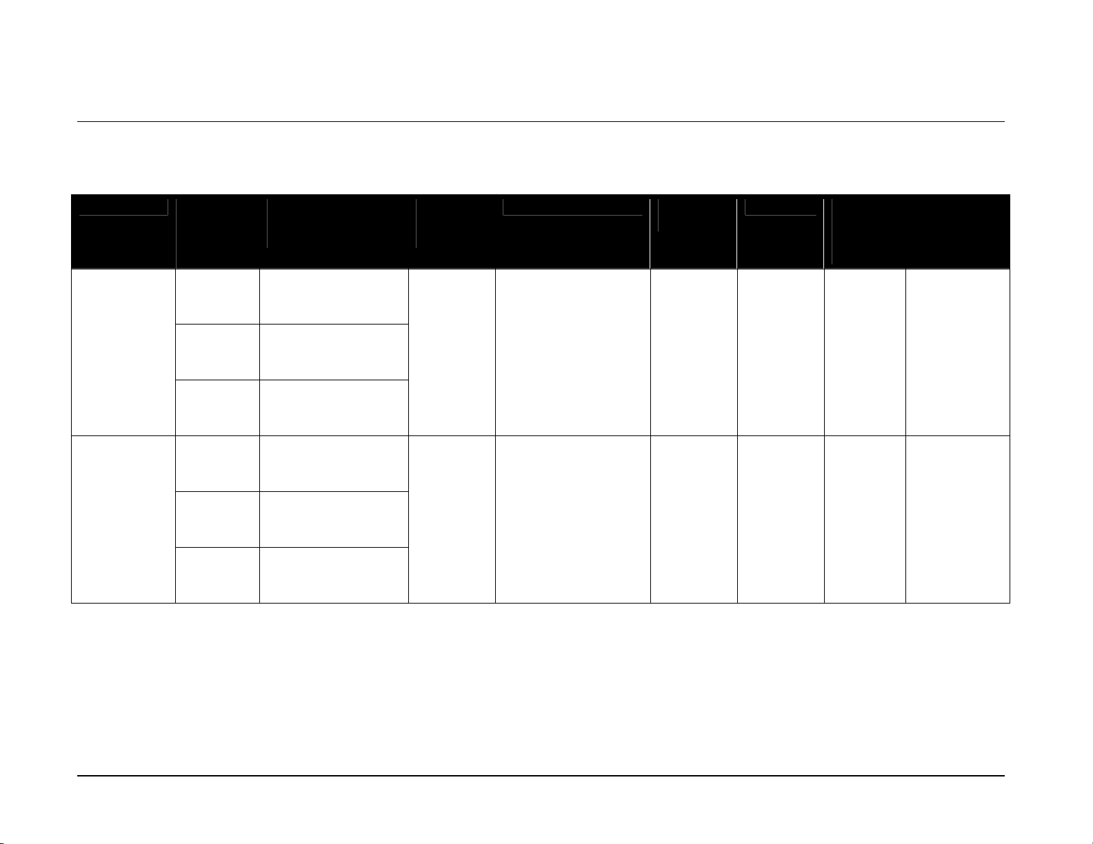
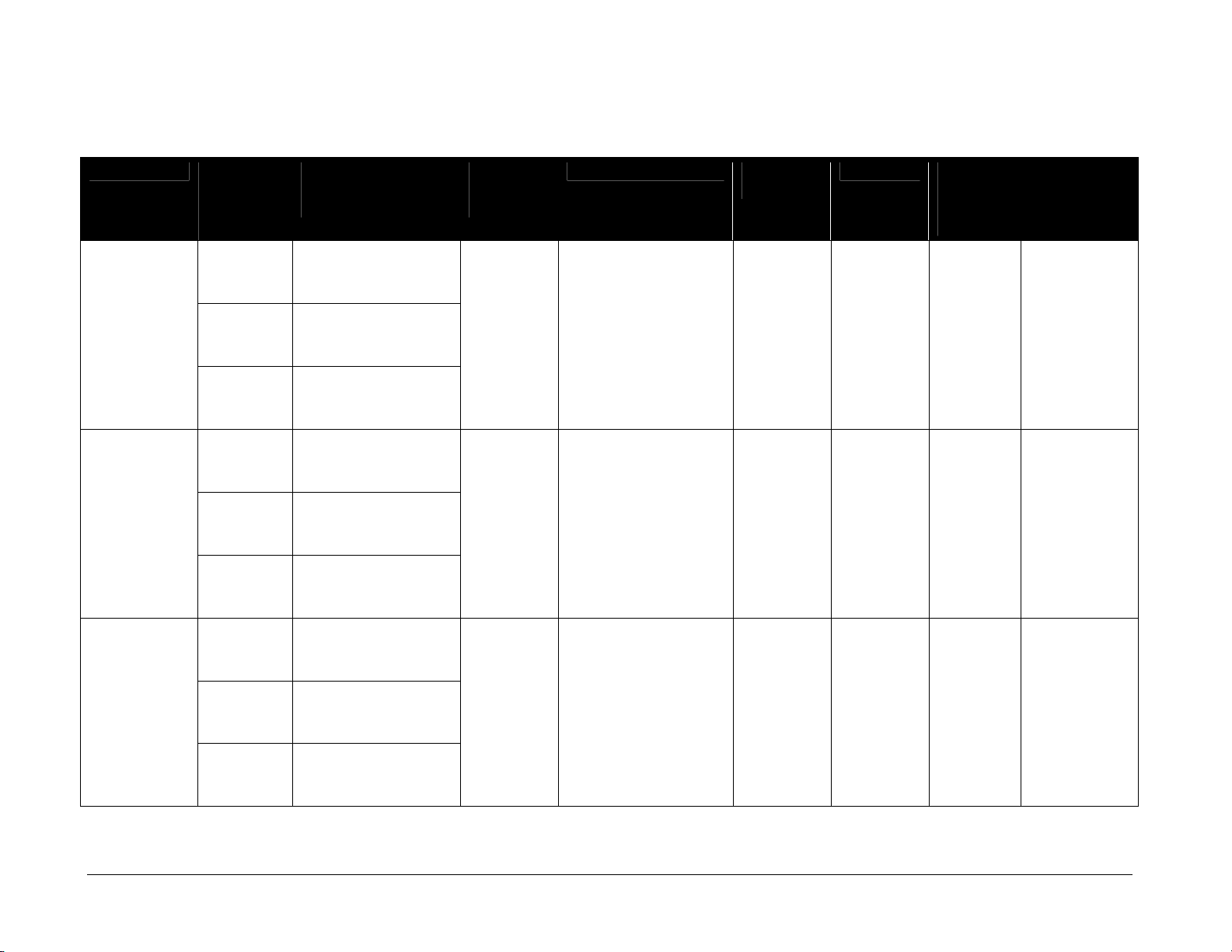
3.1 Multi-Section Scoreboards
Note: Signal wires must be a minimum of 22 gauge with shield. Daktronics recommends using W-1234.
(Continued from previous page)
Model Number
of
Sections
BA-1518-11
BA-1518-11
w/TNMC
2 Total H8'-0", W16'-0", D6"
Top H3'-0", W16'-0", D6"
Bottom H5'-0", W16'-0", D6"
2 Total H8'-0", W16'-0", D6"
Top H3'-0", W16'-0", D6"
Bottom H5'-0", W16'-0", D6"
Dimensions
(Height, Width,
Depth)
(2438 mm, 4877 mm,
152 mm)
(914 mm, 4877 mm,
152 mm)
(1524 mm, 4877 mm,
152 mm)
(2438 mm, 4877 mm,
152 mm)
(914 mm, 4877 mm,
152 mm)
(1524 mm, 4877 mm,
152 mm)
Weight
Uncrated
(Crated)
400 lb
182 kg
(845 lb)
(383 kg)
480 lb
218 kg
(912 lb)
(414 kg)
Digit Size Maximum
Wattage
¡ Indicators
2" (51 mm)
¡ All Others
18" (457 mm)
¡ Indicators
2" (51 mm)
¡ All Others
18" (457 mm)
(Continued on the next page)
250 W 120 V AC 2.1 A A1 63
550 W 120 V AC 4.6 A A1 63
Power Amps Per
Line
(Single
Phase)
Driver
Number and
Address
3-2 Specifications
Page 13
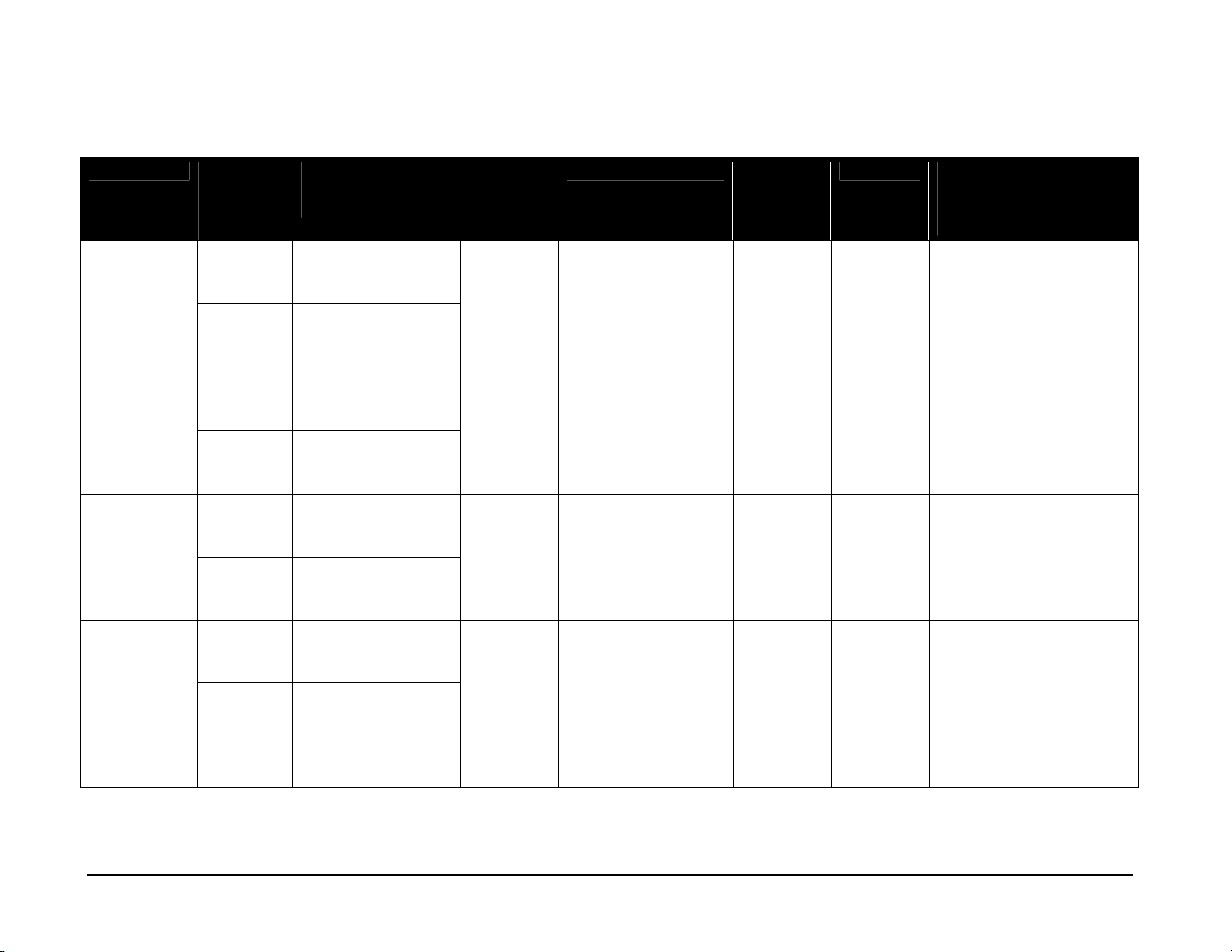
(Continued from previous page)
Model Number
of
Sections
BA-1524-11
2 Total H9'-0", W16'-0", D6"
Top H4'-0", W16'-0", D6"
Bottom H5'-0", W16'-0", D6"
BA-2007-11
4 Total H9'-4", W36'-0", D6"
w/TNMC
2 Top H4'-0", W18'-0", D6"
2 Bottom H5'-4", W18'-0", D6"
Dimensions
(Height, Width,
Depth)
(2743 mm, 4877 mm,
152 mm)
(2743 mm, 4877 mm,
152 mm)
(1524 mm, 4877 mm,
152 mm)
(2845 mm, 10973
mm, 152 mm)
(1219 mm, 5486 mm,
152 mm)
(1626 mm, 5486 mm,
152 mm)
Weight
Uncrated
(Crated)
480 lb
218 kg
(1020 lb)
(463 kg)
840 lb
381 kg
2 crates
(700 lb)
(318 kg)
(1125 lb)
(510 kg)
Digit Size Maximum
Wattage
¡ Runs, Hits, Errors
340 W 120 V AC 2.8 A A1 63
18" (457 mm)
¡ Indicators
2" (51 mm)
¡ All Others
24" (610 mm)
¡ Innings, Runs, Hits,
1000 W 120 V AC 8.0 A A1 64
Errors
18" (457 mm)
¡ All Others
24" (610 mm)
Power Amps Per
Line
(Single
Phase)
Driver
Number and
Address
A2
A3 66
A4 11
65
BA-3718-11
4 Total H7'-0", W28'-0", D6"
(2134 mm, 8534 mm,
152 mm)
2 Top H3'-0", W14'-0", D6'
(914 mm, 8534 mm,
152 mm)
2 Bottom H4'-0", W14'-0", D6"
(1219 mm, 4267 mm,
640 lb
291 kg
2 crates
(825 lb)
(374 kg)
(525 lb)
(238 kg)
¡ Innings, Runs, Hits,
Errors
15" (381 mm)
¡ All Others
18" (457 mm)
650 W 120 V AC 5.5 A A1 64
A2
A3 66
65
152 mm)
(Continued on the next page)
Specifications 3-3
Page 14

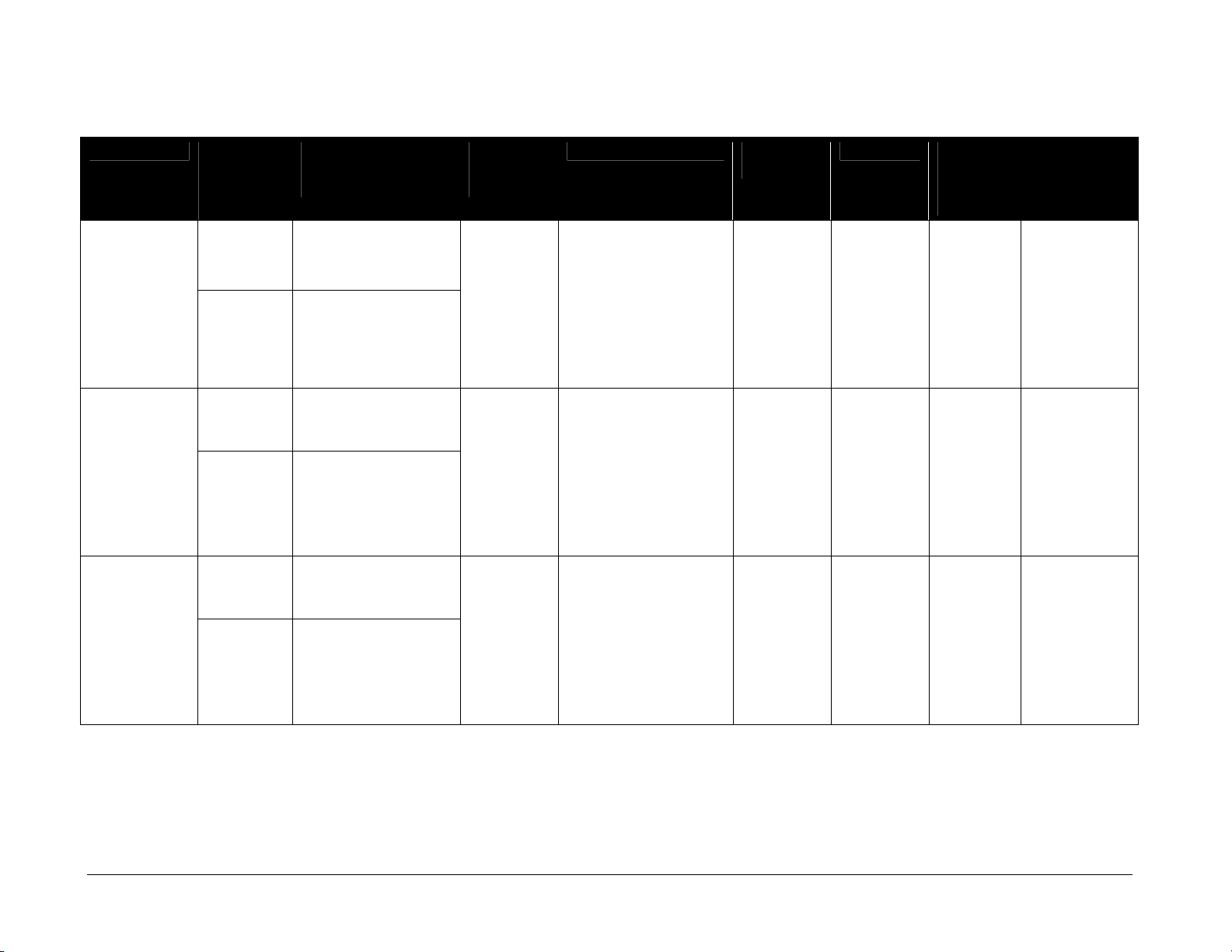
(Continued from previous page)
Model Number
of
Sections
BA-3718-11
4 Total H7'-0", W28'-0", D6"
w/TNMC
2 Top H3'-0", W14'-0", D6"
2 Bottom H4'-0", W14'-0", D6"
BA-3724-11
4 Total H9'-4", W36'-0", D6"
2 Top H4'-0", W18'-0", D6"
2 Bottom H5'-4", W18'-0", D6"
Dimensions
(Height, Width,
Depth)
(2134 mm, 8534 mm,
152 mm)
(914 mm, 8534 mm,
152 mm)
(1219 mm, 4267 mm,
152 mm)
(2845 mm, 10973
mm, 152 mm)
(2845 mm, 5486 mm,
152 mm)
(1626 mm, 5486 mm,
152 mm)
Weight
Uncrated
(Crated)
720 lb
327 kg
2 crates
(746 lb)
(338 kg)
(468 lb)
(212 kg)
840 lb
381 kg
2 crates
(700 lb)
(318 kg)
(1125 lb)
(510 kg)
Digit Size Maximum
Wattage
¡ Innings, Runs, Hits,
950 W 120 V AC 7.8 A A1 64
Errors
15" (381 mm)
¡ All Others
18" (457 mm)
¡ Innings, Runs, Hits,
695 W 120 V AC
Errors
18" (457 mm)
¡ All Others
24" (610 mm)
Power Amps Per
Line
(Single
Phase)
5.8 A A1 64
Driver
Number and
Address
A2
A3 66
A2
A3 66
65
65
BA-3724-11
w/TNMC
4 Total H9'-4", W36'-0", D6"
(2845 mm, 10973
mm, 152 mm)
960 lb
435 kg
2 crates
(856 lb)
(388 kg)
¡ Innings, Runs, Hits,
Errors
18" (456 mm)
¡ All Others
24" (610 mm)
990 W 120 V AC 8.25 A A1 64
A2
A3 66
65
(1112 lb)
(504 kg)
(Continued on the next page)
3-4 Specifications
Page 15

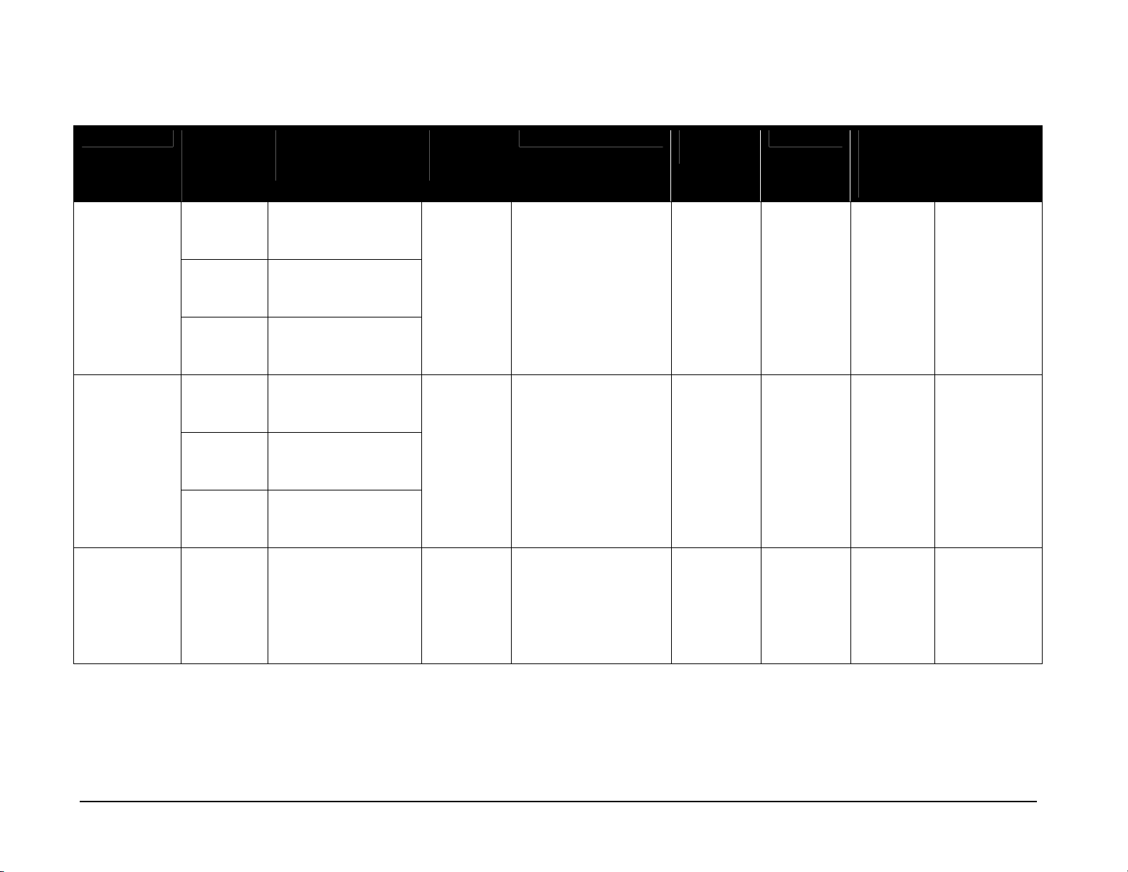
(Continued from previous page)
Model Number
of
Sections
FB-1424-11
2 Total H8'-0", W18'-0", D6"
Top and
Bottom
FB-1430-11
2 Total H8-0", W25'-0", D6"
Top and
Bottom
FB-1430-11
2 Total H8-0", W25'-0", D6"
w/TNMC
Top and
Bottom
FB-1524-11
2 Total H8'-0", W18'-0", D6"
Top and
Bottom
FB-1524-11
2 Total H8'-0", W18'-0", D6"
w/TNMC
Top and
Bottom
Dimensions
(Height, Width,
Depth)
(2438 mm, 5486 mm,
152 mm)
H4'-0", W18'-0", D6"
(1219 mm, 5486 mm,
152 mm)
(2438 mm, 7620 mm,
152 mm)
H4'-0", W25'-0", D6"
(1219 mm, 7620 mm,
152 mm)
(2438 mm, 7620 mm,
152 mm)
H4'-0", W25'-0", D6"
(1219 mm, 7620 mm,
152 mm)
(2438 mm, 5486 mm,
152 mm)
H4'-0", W18'-0", D6"
(1219 mm, 5486 mm,
152 mm)
(2438 mm, 5486 mm,
152 mm)
H4'-0", W18'-0", D6"
(1219 mm, 5486 mm,
152 mm)
Weight
Uncrated
(Crated)
400 lb
182 kg
(805 lb)
(365 kg)
560 lb
254 kg
(1068 lb)
(484 kg)
760 lb
345 kg
(1444 lb)
(655 kg)
400 lb
182 kg
(805 lb)
(365 kg)
520 lb
236 kg
(844 lb)
(383 kg)
Digit Size Maximum
Wattage
¡ Indicators
8" (203 mm)
¡ All Others
24" (610 mm)
¡ Clock
30" (457 mm)
360 W 120 V AC 3 A A1 12
¡ Indicators
8" (203 mm)
¡ All Others
24" (610 mm)
¡ Clock
30" (457 mm)
660 W 120 V AC 5.5 A A1 12
¡ Indicators
8" (203 mm)
¡ All Others
24" (610 mm)
¡ Indicators
8" (203 mm)
360 W 120 V AC 3 A A1 12
¡ All Others
24" (610 mm)
¡ Indicators
8" (203 mm)
660 W 120 V AC 5.5 A A1 63
¡ All Others
24" (610 mm)
(Continued on the next page)
Power Amps Per
Line
(Single
Phase)
Driver
Number and
Address
Specifications 3-5
Page 16
(Continued from previous page)
Model Number
of
Sections
FB-1530-11
2 Total H8'-0", W25'-0", D6"
Top and
Bottom
FB-1530-11
2 Total H8'-0", W25'-0", D6"
w/TNMC
Top and
Bottom
FB-1624-11
2 Total H8'-0", W18'-0", D6"
Top and
Bottom
Dimensions
(Height, Width,
Depth)
(2438 mm, 7620 mm,
152 mm)
H4'-0", W25'-0", D6"
(1219 mm, 7630 mm,
152 mm)
(2438 mm, 7620 mm,
152 mm)
H4'-0", W25'-0", D6"
(1219 mm, 7630 mm,
152 mm)
(2438 mm, 5486 mm,
152 mm)
H4'-0", W18'-0", D6"
(1219 mm, 5486 mm,
152 mm)
Weight
Uncrated
(Crated)
580 lb
263 kg
(1102 lb)
(499 kg)
700 lb
318 kg
(1330 lb)
(603 kg)
440 lb
200 kg
(900 lb)
(408 kg)
Digit Size Maximum
Wattage
¡ Clock
30" (457 mm)
430 W 120 V AC 3.6 A A1 12
¡ Indicators
8" (203 mm)
¡ All Others
24" (610 mm)
¡ Clock
30" (457 mm)
730 W 120 V AC 6.1 A A1 12
¡ Indicators
8" (203 mm)
¡ All Others
24" (610 mm)
¡ Indicators
8" (203 mm)
390 W 120 V AC 3.25 A A1 15
¡ All Others
24" (610 mm)
Power Amps Per
Line
(Single
Phase)
Driver
Number and
Address
A2 16
FB-1630-11
2 Total H8'-0", W25'-0", D6"
(2438 mm, 7620 mm,
152 mm)
Top and
Bottom
H4'-0", W25'-0", D6"
(1219 mm, 7630 mm,
152 mm)
600 lb
272 kg
(1140 lb)
(517 kg)
¡ Clock
30" (457 mm)
¡ Indicators
8" (203 mm)
¡ TOL
18" (457 mm)
395 W 120 V AC 3.3 A A1 15
A2 16
¡ All Others
24" (610 mm)
(Continued on the next page)
3-6 Specifications
Page 17

(Continued from previous page)
Model Number
of
Sections
FB-1630-11
2 Total H8'-0", W25'-0", D6"
w/TNMC
Top and
Bottom
FB-1630L-11
2 Total H8'-0", W32'-0", D6"
Top and
Bottom
FB-1630L-11
2 Total H8'-0", W32'-0", D6"
w/TNMC
Top and
Bottom
Dimensions
(Height, Width,
Depth)
(2438 mm, 7620 mm,
152 mm)
H4'-0", W25'-0", D6"
(1219 mm, 7630 mm,
152 mm)
(2438 mm, 9754 mm,
152 mm)
H4'-0", W32'-0", D6"
(1219 mm, 9754 mm,
152 mm)
(2438 mm, 9754 mm,
152 mm)
H4'-0", W32'-0", D6"
(1219 mm, 9754 mm,
152 mm)
Weight
Uncrated
(Crated)
620 lb
281 kg
(1178 lb)
(534 kg)
720 lb
327 kg
(1368 lb)
(621 kg)
840 lb
381 kg
(1596 lb)
(724 kg)
Digit Size Maximum
Wattage
¡ Clock
30" (457 mm)
695 W 120 V AC 5.8 A A1 15
¡ Indicators
8" (203 mm)
¡ TOL
18" (457 mm)
¡ All Others
24" (610 mm)
¡ Clock
30" (457 mm)
395 W 120 V AC 3.3 A A1 15
¡ Indicators
8" (203 mm)
¡ TOL
18" (457 mm)
¡ All Others
24" (610 mm)
¡ Clock
30" (457 mm)
695 W 120 V AC 5.8 A A1 15
¡ Indicators
8" (203 mm)
¡ TOL
18" (457 mm)
¡ All Others
24" (610 mm)
(Continued on the next page)
Power Amps Per
Line
(Single
Phase)
Driver
Number and
Address
A2 16
A2 16
A2 16
Specifications 3-7
Page 18

(Continued from previous page)
Model Number
of
Sections
FB-1730-11
2 Total H8'-0", W25'-0", D6"
Top and
Bottom
FB-1730-11
2 Total H8’-0”, W25’-0”, D6”
w/TNMC
Top and
Bottom
FB-1830-11
2 Total H8'-0", W25'-0", D6"
Top and
Bottom
Dimensions
(Height, Width,
Depth)
(2438 mm, 7620 mm,
152 mm)
H4'-0", W25'-0", D6"
(1219 mm, 7630 mm,
152 mm)
(2438 mm, 7620 mm,
152 mm)
H4’-0”, W25’-0”, D6”
(1219 mm, 7620 mm,
152 mm)
(2438 mm, 7620 mm,
152 mm)
H4'-0", W25'-0", D6"
(1219 mm, 7630 mm,
152 mm)
Weight
Uncrated
(Crated)
620 lb
281 kg
(1178 lb)
(534 kg)
740 lb
336 kg
(1406 lb)
(638 kg)
640 lb
291 kg
(1550 lb)
(703 kg)
Digit Size Maximum
Wattage
¡ Clock
30" (457 mm)
400 W 120 V AC 3.3 A A1 15
¡ Indicators
8" (203 mm)
¡ TOL
18" (457 mm)
¡ All Others
24" (610 mm)
¡ Clock
30" (457 mm)
700 W 120 V AC 5.8 A A1 15
¡ Indicators
8" (203 mm)
¡ TOL
18" (457 mm)
¡ All Others
¡ 24" (610 mm)
¡ Clock
30" (457 mm)
430 W 120 V AC 3.6 A A1 15
¡ Indicators
8" (203 mm)
¡ TOL
18" (457 mm)
¡ All Others
24" (610 mm)
(Continued on the next page)
Power Amps Per
Line
(Single
Phase)
Driver
Number and
Address
A2 16
A2 16
A2 16
3-8 Specifications
Page 19
(Continued from previous page)
Model Number
of
Sections
FB-1830-11
2 Total H8'-0", W25'-0", D6"
w/TNMC
Top and
Bottom
FB-1830L-11
2 Total H8'-0", W32'-0", D6"
Top and
Bottom
FB-1830L-11
2 Total H8'-0", W32'-0", D6"
w/TNMC
Top and
Bottom
Dimensions
(Height, Width,
Depth)
(2438 mm, 7620 mm,
152 mm)
H3'-0", W14'-0", D6'
(914 mm, 8534 mm,
152 mm)
(2438 mm, 9754 mm,
152 mm)
H4'-0", W32'-0", D6"
(1219 mm, 9754 mm,
152 mm)
(2438 mm, 9754 mm,
152 mm)
H4'-0", W32'-0", D6"
(1219 mm, 9754 mm,
152 mm)
Weight
Uncrated
(Crated)
760 lb
345 kg
(1444 lb)
(655 kg)
780 lb
354 kg
(1482 lb)
(672 kg)
900 lb
408 kg
(1710 lb)
(776 kg)
Digit Size Maximum
Wattage
¡ Clock
30" (457 mm)
730 W 120 V AC 6.1 A A1 15
¡ Indicators
8" (203 mm)
¡ TOL
18" (457 mm)
¡ All Others
24" (610 mm)
¡ Clock
30" (457 mm)
450 W 120 V AC 3.8 A A1 15
¡ Indicators
8" (203 mm)
¡ TOL
18" (457 mm)
¡ All Others
24" (610 mm)
¡ Clock
30" (457 mm)
755 W 120 V AC 6.3 A A1 15
¡ Indicators
8" (203 mm)
¡ TOL
18" (457 mm)
¡ All Others
24" (610 mm)
(Continued on the next page)
Power Amps Per
Line
(Single
Phase)
Driver
Number and
Address
A2 16
A2 16
A2 16
Specifications 3-9
Page 20
(Continued from previous page)
Model Number
of
Sections
FB-2001-11
2 Total H10'-0", W32'-0", D6"
Top H6'-0", W32'-0", D6"
Bottom H4'-0", W32'-0", D6"
FB-2002-11
2 Total H8'-0", W20'-0", D6"
Top H6'-0", W20'-0", D6"
Bottom H4'-0", W20'-0", D6"
Dimensions
(Height, Width,
Depth)
(3048 mm, 9754 mm,
152 mm)
(1829 mm, 9754 mm,
152 mm)
(1219 mm, 9754 mm,
152 mm)
(2438 mm, 6096 mm,
152 mm)
(1219 mm, 6096 mm,
152 mm)
(1219 mm, 6096 mm,
152 mm)
Weight
Uncrated
(Crated)
940 lb
426 kg
(1786 lb)
(810 kg)
520 lb
236 kg
(988 lb)
(448 kg)
Digit Size Maximum
Wattage
¡ Clock
30" (457 mm)
455 W 120 V AC 3.8 A A1 15
¡ Indicators
8" (203 mm)
¡ TOL
18" (457 mm)
¡ All Others
24" (610 mm)
¡ Indicators
8" (203 mm)
365 W 120 V AC 3 A A1 15
¡ TOL
18" (457 mm)
¡ All Others
24" (610 mm)
Power Amps Per
Line
(Single
Phase)
Driver
Number and
Address
A2 16
A2 16
FB-2003-11
w/TNMC
2 Total H8'-0", W20'-0", D6"
(2438 mm, 6096 mm,
152 mm)
660 lb
299 kg
(1254 lb)
(569 kg)
¡ Indicators
8" (203 mm)
¡ TOL
18" (457 mm)
¡ All Others
695 W 120 V AC 5.8 A A1 15
A2 16
24" (610 mm)
(Continued on the next page)
3-10 Specifications
Page 21

((Continued from previous page)
Model Number
of
Sections
MS-2009-11
2 Total H10'-0", W25'-0", D6"
Top and
Bottom
MS-2118-11
2 Total H8'-0", W12'-0", D6"
Top and
Bottom
SO-1424-11
2 Total H8'-0", W18'-0", D6"
Top and
Bottom
Dimensions
(Height, Width,
Depth)
(3048 mm, 6096 mm,
152 mm)
H5'-0", W25'-0", D6"
(1524 mm, 6096 mm,
152 mm)
(2438 mm, 3658 mm,
152 mm)
H4'-0", W12'-0", D6"
(1219 mm, 5486 mm,
152 mm)
(2438 mm, 5486 mm,
152 mm)
H4'-0", w18'-0", D6"
(1219 mm, 5486 mm,
152 mm)
Weight
Uncrated
(Crated)
480 lb
218 kg
(912 lb)
(414 kg)
275 lb
125 kg
(390 lb)
(176 kg)
400 lb
181 kg
(805 lb)
(365 kg)
Digit Size Maximum
Wattage
¡ Clock, Score,
360 W 120 V AC 4.7 A A1 71
Period
24" (610 mm)
¡ All Others
18" (457 mm)
¡ Clock, Score,
370 W 120 V AC 3.1 A A1 71
Period
18" (457 mm)
¡ Penalty
15" (381 mm)
¡ Indicators
8" (203 mm)
335 W 120 V AC 2.8 A A1 12
¡ All Others
24" (610 mm)
Power Amps Per
Line
(Single
Phase)
Driver
Number and
Address
A2 72
A2 72
SO-1624-11
2 Total H8'-0", W18'-0", D6"
(2438 mm, 5486 mm,
152 mm)
Top and
Bottom
H4'-0", W18'-0", D6"
(1219 mm, 5486 mm,
440 lb
200 kg
(900 lb)
(408 kg)
¡ Indicators
8" (203 mm)
¡ All Others
24" (610 mm)
385 W 120 V AC 3.2 A A1 13
A2 14
152 mm)
(Continued on the next page)
Specifications 3-11
Page 22

(Continued from previous page)
Model Number
of
Sections
SO-1624-11
2 Total H8'-0", W18'-0", D6"
w/TNMC
Top and
Bottom
SO-1830-11
2 Total H8'-0", W25'-0", D6"
Top and
Bottom
SO-1830-11
2 Total H8'-0", W25'-0", D6"
w/TNMC
Top and
Bottom
Dimensions
(Height, Width,
Depth)
(2438 mm, 5486 mm,
152 mm)
H4'-0", W18'-0", D6"
(1219 mm, 5486 mm,
152 mm)
(2438 mm, 7620 mm,
152 mm)
H4'-0", W25'-0", D6"
(1219 mm, 762 mm,
152 mm)
(2438 mm, 7620 mm,
152 mm)
H4'-0", W25'-0", D6"
(1219 mm, 762 mm,
152 mm)
Weight
Uncrated
(Crated)
520 lb
236 kg
(988 lb)
(448 kg)
560 lb
254 kg
(1064 lb)
(483 kg)
680 lb
308 kg
(1292 lb)
(586 kg)
Digit Size Maximum
Wattage
¡ Indicators
8" (203 mm)
685 W 120 V AC 5.7 A A1 13
¡ All Others
24" (610 mm)
¡ Clock
30" (762 mm)
440 W 120 V AC 3.7 A A1 15
¡ TOL
18" (457 mm)
¡ Indicators
8" (203 mm)
¡ All Others
24" (610 mm)
¡ Clock
30" (762 mm)
740 W 120 V AC 6.2 A A1 15
¡ TOL
18" (457 mm)
¡ Indicators
8" (203 mm)
¡ All Others
24" (610 mm)
(Continued on the next page)
Power Amps Per
Line
(Single
Phase)
Driver
Number and
Address
A2 14
A2 16
A2 16
3-12 Specifications
Page 23

(Continued from previous page)
Model Number
of
Sections
SO-1830L-11
2 Total H8'-0", W32'-0", D6"
Top and
Bottom
SO-1830L-11
2 Total H8'-0", W32'-0", D6"
w/TNMC
Top and
Bottom
SO-1930-11
2 Total H8'-0", W25'-0", D6"
Top and
Bottom
Dimensions
(Height, Width,
Depth)
(2438 mm, 9754 mm,
152 mm)
H4'-0", W32'-0", D6"
(1219 mm, 9754 mm,
152 mm)
(2438 mm, 9754 mm,
152 mm)
H4'-0", W32'-0", D6"
(1219 mm, 9754 mm,
152 mm)
(2438 mm, 7620 mm,
152 mm)
H4'-0", W25'-0", D6"
(1219 mm, 7620 mm,
152 mm)
Weight
Uncrated
(Crated)
720 lb
327 kg
(1368 lb)
(621 kg)
840 lb
381 kg
(1596 lb)
(724 kg)
560 lb
254 kg
(1064 lb)
(483 kg)
Digit Size Maximum
Wattage
¡ Clock
30" (762 mm)
440 W 120 V AC 3.7 A A1 15
¡ TOL
18" (457 mm)
¡ Indicators
8" (203 mm)
¡ All Others
24" (610 mm)
¡ Clock
30" (762 mm)
740 W 120 V AC 6.2 A A1 15
¡ TOL
18" (457 mm)
¡ Indicators
8" (203 mm)
¡ All Others
24" (610 mm)
¡ Clock
30" (762 mm)
470 W 120 V AC 4 A A1 15
¡ TOL
18" (457 mm)
¡ Indicators
8" (203 mm)
¡ All Others
24" (610 mm)
(Continued on the next page)
Power Amps Per
Line
(Single
Phase)
Driver
Number and
Address
A2 16
A2 16
A2 16
Specifications 3-13
Page 24

(Continued from previous page)
Model Number
of
Sections
SO-1930-11
2 Total H8'-0", W25'-0", D6"
w/TNMC
Top and
Bottom
Dimensions
(Height, Width,
Depth)
(2438 mm, 7620 mm,
152 mm)
H4'-0", W25'-0", D6"
(1219 mm, 7620 mm,
152 mm)
Weight
Uncrated
(Crated)
950 lb
432 kg
(1550 lb)
(703 kg)
Digit Size Maximum
Wattage
¡ Clock
30" (762 mm)
770 W 120 V AC 6.4 A A1 15
¡ TOL
18" (457 mm)
¡ Indicators
8" (203 mm)
¡ All Others
24" (610 mm)
Power Amps Per
Line
(Single
Phase)
Driver
Number and
Address
A2 16
3-14 Specifications
Page 25

Section 4: Component Locations
Use the following drawings to determine the location of scoreboard components. The drawings are
listed below by model number and inserted in the Appendix in alphanumeric order by drawing
number.
Reference Drawings:
Component Locations, BA-1518-11................................................... Drawing A-141077
Component Locations, BA-1518-11 w/TNMC .................................... Drawing A-144637
Component Locations, BA-1524-11................................................... Drawing A-141745
Component Locations, BA-2007-11 w/LED TNMC ............................ Drawing A-147199
Component Locations, BA-3718-11................................................... Drawing A-141749
Component Locations, BA-3718-11 w/TNMC .................................... Drawing A-144659
Component Locations, BA-3724-11................................................... Drawing A-141751
Component Locations, BA-3724-11 w/TNMC .................................... Drawing A-144678
Component Locations, FB-1424-11................................................... Drawing A-142712
Component Locations, FB-1430-11................................................... Drawing A-147264
Component Locations, FB-1524-11 (w/TNMC).................................. Drawing A-142650
Component Locations, FB-1530-11................................................... Drawing A-145498
Component Locations, FB-1624-11................................................... Drawing A-142652
Component Locations, FB-1630-11................................................... Drawing A-148369
Component Locations, FB-1630L-11................................................. Drawing A-148432
Component Locations, FB-1730-11................................................... Drawing A-148018
Component Locations, FB-1830-11................................................... Drawing A-145120
Component Locations, FB-1830L-11................................................. Drawing A-145554
Component Locations, FB-2001-11................................................... Drawing A-148468
Component Locations, FB-2002-11................................................... Drawing A-148476
Component Locations, FB-2003-11................................................... Drawing A-148545
Component Locations, MS-2009-11.................................................. Drawing A-149704
Component Locations, MS-2118-11.................................................. Drawing A-142620
Component Locations, SO-1624-11 .................................................. Drawing A-142741
Component Locations, SO-1424-11 .................................................. Drawing A-142742
Component Locations, SO-1830-11 .................................................. Drawing A-148537
Component Locations, SO-1830L-11 ................................................ Drawing A-146372
Component Locations, SO-1930-11 .................................................. Drawing A-148531
Component Location
4-1
Page 26

Page 27
Section 5: Schematics
A
A
A
A
A
A
A
A
A
A
A
A
A
A
A
A
A
A
A
A
Reference Drawings:
Schematic; 1 Driver ........................................................................... Drawing A-141799
Schematic; 1 Driver w/TNMC ............................................................ Drawing A-141806
Schematic; 2 Drivers ......................................................................... Drawing A-141807
Schematic; 2 Drivers w/TNMC........................................................... Drawing A-141808
Schematic; 3 Drivers ......................................................................... Drawing A-142358
Schematic; 3 Drivers w/TNMC...........................................................Drawing B-142360
Schematic; 3 Drivers w/TNMC & SOP Driver ....................................Drawing B-146392
Use the following table to determine the schematic for your scoreboard. The drawings are listed
below by model number; they have been inserted in the Appendix in alphanumeric order by drawing
number.
K Note: All scoreboards listed in this manual are equipped with 16-column drivers.
Models Schematic Name Drawing
BA-1518 Schematic; 1 Driver
BA-1518 w/TNMC Schematic; 1 Driver w/TNMC
BA-1524 Schematic; 1 Driver
BA-2007 w/TNMC Schematic; 3 Drivers w/TNMC & SOP Driver B-146392
BA-3718 Schematic; 3 Drivers
BA-3718 w/TNMC Schematic; 3 Drivers w/TNMC B-142360
BA-3724 Schematic; 3 Drivers
BA-3724 w/TNMC Schematic; 3 Drivers w/TNMC B-142360
FB-1424 Schematic; 1 Driver
FB-1424 w/TNMC Schematic; 1 Driver w/TNMC
FB-1430 Schematic; 1 Driver
FB-1430 w/TNMC Schematic; 1 Driver w/TNMC
FB-1524 Schematic; 1 Driver
FB-1524, w/TNMC Schematic; 1 Driver w/ TNMC
FB-1530 Schematic; 1 Driver
FB-1530 w/TNMC Schematic; 1 Driver w/TNMC
FB-1624 Schematic; 2 Drivers
-141799
-141806
-141799
-142358
-142358
-141799
-141806
-141799
-141806
-141799
-141806
-141799
-141806
-141807
FB-1630 Schematic; 2 Drivers
FB-1630 w/TNMC Schematic; 2 Drivers w/TNMC
FB-1630L Schematic; 2 Drivers
FB-1630L w/TNMC Schematic; 2 Drivers w/TNMC
FB-1730 Schematic; 2 Drivers
FB-1730 w/TNMC Schematic; 2 Drivers w/TNMC
(Continued on the next page)
Schematics
-141807
-141808
-141807
-141808
-141807
-141808
5-1
Page 28

A
A
A
A
A
A
A
A
A
A
A
A
A
A
A
A
A
A
A
A
(Continued from the previous page)
Models Schematic Name Drawing
FB-1830 Schematic; 2 Drivers
FB-1830 w/TNMC Schematic; 2 Drivers w/TNMC
FB-1830L Schematic; 2 Drivers
FB-1830L w/TNMC Schematic; 2 Drivers w/TNMC
FB-2001 Schematic; 2 Drivers
FB-2002 Schematic; 2 Drivers
FB-2003 Schematic; 2 Drivers
FB-2003 w/TNMC Schematic; 2 Drivers w/TNMC
MS-2009 Schematic; 2 Drivers
MS-2118 Schematic; 2 Drivers
SO-1424 Schematic; 1 Driver
SO-1424 w/TNMC Schematic; 1 Driver w/TNMC
SO-1624 Schematic; 2 Drivers
SO-1624 w/TNMC Schematic; 2 Drivers w/TNMC
SO-1830 Schematic; 2 Drivers
SO-1830 w/TNMC Schematic; 2 Drivers w/TNMC
SO-1830L Schematic; 2 Drivers
-141807
-141808
-141807
-141808
-141807
-141807
-141807
-141808
-141807
-141807
-141799
-141806
-141807
-141808
-141807
-141808
-141807
SO-1830L w/TNMC Schematic; 2 Drivers w/TNMC
SO-1930 Schematic; 2 Drivers
SO-1930 w/TNMC Schematic; 2 Drivers w/TNMC
-141808
-141807
-141808
5-2
Schematics
Page 29
Section 6: Mechanical Installation
Mechanical installation consists of installing concrete footings and steel beams, and mounting the
scoreboard and accompanying ad panels to the beams.
6.1 Scoreboard Protective Devices
K Note: Some owners install devices to protect the display from projectiles. Scoreboard protection
devices not provided by Daktronics must be approved by Daktronics prior to installation. Failure to
follow this approval procedure will void the scoreboard warranty.
Daktronics makes available optional devices, including screens and netting, to help protect the
scoreboard from damage due to normal ball impact.
6.2 Footings and Beams
Reference Drawings:
Installation Specifications, BA-1518 ......................................................Drawing A-55008
Installation Specifications, BA-1524 .................................................... Drawing A-120972
Installation Specifications, BA-3718 .................................................... Drawing A-126455
Installation Specifications; BA-3724 .................................................... Drawing A-126445
Installation Specifications; FB-2002 & FB-2003................................... Drawing A-128044
Installation Specifications; MS-2009.................................................... Drawing A-144415
Installation Specifications; MS-2118.................................................... Drawing A-128206
Beam & Footing Recommendations, FB-XX24...................................... Drawing A-44514
Beam & Footing Recommendations, FB-XX30...................................... Drawing A-44515
Beam Spacings, Football/Track/Soccer................................................. Drawing A-70089
Structure, Football................................................................................. Drawing A-44556
Beam Spacing; Displays w/TNMC ......................................................... Drawing A-84292
Beam and Footing Recommendations, FB-XX30L .............................. Drawing A-158779
Beam and Footing Recommendations FB-200X ................................. Drawing A-160931
Use the following tables to determine, which drawings provide the installation specifications for each
model.
Models Specification Name Drawing
BA-1518-11 Installation Specifications, BA-1518 A-55008
BA-1524-11 Installation Specifications, BA-1524 A-120972
BA-3718-11 Installation Specifications, BA-3718 A-126455
BA-3724-11 Installation Specifications, BA-3724 A-126445
MS-2009-11 Installation Specifications, MS-2009 A-144415
MS-2118-11 Installation Specifications, MS-2118 A-128206
Mechanical Installation
6-1
Page 30
Models Without Team Name
Message Center
FB-1424-11, FB-1524-11, FB-162411, SO-1424-11, SO-1624-11
FB-2001, FB-2002-11, FB-2003-11
FB-1430-11, FB-1530-11, FB-163011, FB-1730-11, FB-1830-11, FB2001-11, SO-1830-11, SO-1830L11, SO-1930-11
FB-1630L-11, FB-1830L-11
Reference Drawings
Beam & Footing Recommendations,
FB-XX24
Beam Spacings, Football/Track/Soccer A-70089
Structure, Football A-44556
Beam Spacings, Football/Track/Soccer A-70089
Structure, Football A-44556
Beam and Footing Recommendations,
FB-200X
Installation Specifications, FB-2002 &
FB-2003
Beam & Footing Recommendations,
FB-XX30
Beam Spacings, Football/Track/Soccer A-70089
Structure, Football A-44556
Beam and Footing Recommendations,
FB-XX30L
A-44514
A-160931
A-128044
A-44515
A-158779
Models With Team Name
Message Center
FB-1424-11, FB-1524-11, SO-142411, SO-1624-11
FB-1430-11, FB-1530-11, FB-163011, FB-1730-11, FB-1830-11, SO1830-11, SO-1830L-11, SO-193011
FB-1630L-11, FB-1830L-11
Beam Spacings, Football/Track/Soccer A-70089
Structure, Football A-44556
Reference Drawings
Beam & Footing Recommendations,
FB-XX24
Beam Spacing, Football/Track/Soccer A-84292
Structure, Football A-44556
Beam & Footing Recommendations,
FB-XX30
Beam Spacing, Displays w/TNMC A-84292
Structure, Football A-44556
Beam & Footing Recommendations,
FB-XX30L
Beam Spacing, Football/Track/Soccer A-70089
A-44514
A-44515
A-158779
6-2
Structure, Football A-44556
(Continued on the next page)
Mechanical Installation
Page 31

(Continued from the previous page)
Models With Team Name
Reference Drawings
Message Center
FB-2003-11
Installation Specifications, FB-2002 &
FB-2003
Beam Spacing, Football/Track/Soccer A-70089
Structure, Football A-44556
Beam and Footing Recommendations,
FB-200X
A-128044
A-160931
These drawings specify the number of beams and the recommended spacing between them.
The drawings also indicate the size of beams required to support the scoreboard at different heights
and under various wind speed conditions. All of the beam specifications illustrate "W"-shape steel
beams (wide-flange I-beams). The first number indicates the front-to-rear depth of the beam, and the
second number indicates the weight in pounds per foot of length.
Column and footing size drawings are estimates only and are not intended for construction purposes.
Columns and footings and all connection details must be designed and certified by a professional
engineer licensed to practice in the state in which the display will be installed. Be sure that your
installation complies with local building codes and is suitable for your particular soil and wind
conditions.
Daktronics assumes no liability for installations derived from the information provided in this
manual or installations designed and installed by others.
Mechanical Installation
6-3
Page 32

6.3 Lifting the Scoreboard
Reference Drawings:
Lifting Scoreboard ................................................................................. Drawing A-44548
Large scoreboard sections and message centers are shipped equipped with eyebolts that are used to
lift the displays. The eyebolts are located along the top of the cabinet for each scoreboard or
scoreboard section.
Daktronics strongly recommends using a spreader bar, or lifting bar, to lift the display. Using a
spreader bar ensures that the force on the lifting straps or eyebolts is straight up, minimizing lifting
stress. Lifting methods are shown in the illustration below, Figure 3, and in Drawing A-44548.
Figure 3: Lifting the Display
Figure 3 illustrates both the preferred method (left example) and an alternative method (right
example) for lifting a scoreboard. When lifting the display:
+
Use a spreader bar.
+
Use every lifting point provided.
Take special care to ensure the rated load of the eyebolts is not exceeded. Refer to ED7244:
Eyebolts, to determine allowable loads and load angles for the lifting hardware. ED7244 is located in
the Appendix of this manual.
Avoid using other lifting methods. Cables and chains attached to the eyebolts and directly to a center
lifting point, as shown in the right-hand example in Figure 3, can create a dangerous lateral force on
the eyebolts and may cause the eyebolts to fail. Daktronics scoreboards use
eyebolts mounted to a
1
/8" aluminum plate or steel nut plate, but exceeding load angles or weight
1
/2" and 5/8" shoulder-type
limits could cause the bolts to pull out or the scoreboard cabinet to buckle. In either circumstance, the
result would be serious damage to the scoreboard. If you must use this method, ensure a minimum
angle between the chain and scoreboard of at least 45°.
K Note: Daktronics assumes no liability for scoreboard damage resulting from incorrect setup or
incorrect lifting methods.
Eyebolts are intended for lifting only. Do not attempt to permanently support the display by the
eyebolts.
6-4
Mechanical Installation
Page 33

In typical multi-section installations, the lower scoreboard section is installed first and secured to the
support beams, and the upper section is then placed atop or above the lower section and attached to
the beams. There may be cables extending from the top of the lower section. Guide these cables into
the hole in the bottom of the upper section for later connection.
If installers remove the lift eyebolts when the display is permanently mounted, plug the holes with
bolts and the rubber sealing washers that were removed with the eyebolts. Apply silicone or another
waterproof sealant to the eyebolt openings. Inspect the top and sides of the display for any other holes
or openings that may allow moisture to enter the display, and plug and seal those openings as well.
6.4 Scoreboard Mounting
Reference Drawing:
Installation Method ................................................................................ Drawing A-44412
Panel Mounting Method......................................................................... Drawing A-52187
Installation Specifications, BA-1518 ...................................................... Drawing A-55008
Installation Specifications, BA-1524 .................................................... Drawing A-120972
Installation Specifications, BA-3718 .................................................... Drawing A-126455
Installation Specifications, BA-3724 .................................................... Drawing A-126445
Installation Specifications, MS-2118.................................................... Drawing A-128206
Display Mounting Straps, BA-3718...................................................... Drawing A-114415
Scoreboards can be mounted to two, three, or four poles. Refer to Section 6.2 to determine the centerto-center distance of the poles for each model.
Drawing A-44412 shows that the hardware used for mounting the scoreboard to the beams. Each
section of the scoreboard attaches at the top and the bottom to all the beams, Drawing A-44412 also
show top and side views of the scoreboard secured to the beams. Note that the threaded rods do not
pass through the flanges of the beams, but instead run along both sides of each beam.
Review the illustrations of the mounting hardware in Drawing A-44412, and then follow this
procedure for each section:
1. Loosely attach the inner and outer mounting clamps to the rear flanges of the scoreboard's
horizontal frame members, using the
clamps to fit on either side of the beams.
2. Insert a 1/2" square nut into each mounting clamp. Screw a threaded rod into each of the nuts
from the rear.
3. Position the scoreboard at the front of the beams with the threaded rods extending from the
rear of the clamps, straddling the beams. Raise the scoreboard section to the desired height.
4. Slide clamping angles over the ends of the rods and loosely install the washers and nuts.
5. Make final adjustments in the positioning of the scoreboard. Tighten the 3/8" bolts in the
mounting clamps.
6. Make sure that the threaded rods are perpendicular to the scoreboard, and tighten all of the
1
/2" nuts.
3
/8" bolts. Measure the beam spacing and position the
Mechanical Installation
6-5
Page 34

6.5 Ad Panel Mounting
Reference Drawing:
Ad Panel Mounting................................................................................ Drawing A-52187
Drawing A-52187 shows the mounting of advertising or identification panels.
Mount the ad panel or ad panels in the following manner:
1. Use the mounting channel to determine which hole combination to use. Be sure to keep the
bolts as close to the beam as possible.
2. Using the mounting channel as a template, drill 9/16" holes in the upper and lower rear flange
of the ad panel where the supports will go.
3. Place square nuts inside the channel and thread the bolts through.
4. Lift the ad panel into position with the bolts still in place.
5. Place mounting angles over each pair of bolts and secure with lock washers and hex nuts.
6. When the panel is adjusted to the final desired position, tighten the hex nuts firmly.
When mounting ad panels with back sheets, remove the back sheets above and below the upper and
lower rear flanges of the ad panel where the holes have been drilled. Be sure to replace the back
sheets after placing the square nuts inside the channel and threading the bolts through the holes.
6.6 Optional One- or Two-Line Message Center Mounting
Reference Drawing:
Mounting Detail; 2
Refer to the manual provided with the message center for instructions on how to mount the message
center to the beams using the clamping method. Some retrofit message centers may be mounted
directly to the scoreboard face.
Drawing A-11582 shows the mounting method for a 2
1
/2" Matrix............................................................... Drawing A-115882
1
/2" matrix display.
6-6
Mechanical Installation
Page 35

Section 7: Electrical Installation
Electrical installation consists of the following processes:
+
K Note: Only qualified individuals should perform power routing and termination to the display. It
is the responsibility of the electrical contractor to ensure that all electrical work meets or exceeds
local and national codes.
7.1 Power Requirements
Reference Drawings:
Components 8/16 Pos Power and Signal Entrance............................. Drawing A-109114
Components 2/4 Pos Power and Signal Entrance............................... Drawing A-125977
Refer to the chart in Section 3 to determine circuit specifications and maximum power requirements
for the models described in this manual.
Daktronics outdoor LED scoreboards have been designed for easy access to components, and the
power and control signal hookup has been simplified. Front panels are removable to allow access to
the digits, cabling, and other electronic components.
Correct power installation is imperative for proper display operation. The subsections that follow give
details of power installation. Only qualified individuals should attempt to complete the electrical
installation; untrained personnel should not attempt to install these displays or any of the electrical
components. Improper installation could result in serious damage to the equipment and could be
hazardous to personnel.
Daktronics outdoor scoreboards and timing displays require a dedicated, 120 V circuit for incoming
power. The display itself has no breakers or fuses.
K WARNING: It is critical that the scoreboard circuit be fused at 15 A, and that all conductors
used must be designed to pass a 15 A current in normal operation. Failure to meet wiring and
overcurrent protection device requirements is a violation of the National Electrical Code
void the scoreboard warranty.
All power conductors are 14 AWG, except where 18 AWG wiring is called out on the schematic. All
signal conductors are 22 AWG.
Refer to the outdoor scoreboard schematic listed above and to the chart in Section 1 to determine
circuit specifications and maximum power requirements for the models described in this manual.
Providing power and ground to a disconnect near the scoreboard;
+
Routing power and ground from the main disconnect to the scoreboard power and signal
entrance enclosure;
+
Connecting the scoreboard ground to a grounding electrode at the display location;
+
Routing the control signal cable from the control location to the display location.
®
and will
Electrical Installation
7-1
Page 36

Grounding
Displays MUST be grounded according to the provisions outlined in Article 250 of the
National Electrical Code and according to the specifications in this manual. Daktronics
recommends a resistance-to-ground of 10 ohms or less.
The electrical contractor who is performing the electrical installation can verify ground
resistance. Scoreboard Sales and Service personnel can also perform this service.
The display system must be connected to an earth electrode installed at the display. Proper
grounding is necessary for reliable equipment operation. It also protects the equipment from
damaging electrical disturbances and lightning. The display must be properly grounded or the
warranty will be void. Refer to the schematic, Drawing A-156750, for information on where to
connect the grounding wire. Connection at the duplex receptacle is illustrated in the lower section
of the drawing.
The material for an earth-ground electrode differs from region to region and may vary according
to conditions present at the scoreboard installation site. Consult the National Electrical Code and
any local electrical codes that may apply. The support structure of the display cannot be used as
an earth-ground electrode. The support is generally embedded in concrete, and if it is in earth, the
steel is usually primed or it corrodes, making it a poor ground in either case.
Branch Circuit Grounding
A grounding electrode at separate structures/displays will not be required where only one
branch circuit supplies the structure and branch circuit includes an equipment-grounding
conductor for grounding the non-current-carrying parts of all equipment.
Power Installation
There are two considerations for power installation: installation with ground and neutral
conductors provided, and installation with only a neutral conductor provided. These two power
installations differ slightly, as described in the following subsections:
Installation with Ground and Neutral Conductors Provided
For this type of installation,
the power circuit must
contain an isolated earthground conductor. Under
this circumstance, do not
connect neutral to ground at
the disconnect or at the
display. This would violate
electrical codes and void the
warranty. Use a disconnect
so that all hot lines and
neutral can be disconnected.
The National Electrical Code
requires the use of a lockable power disconnect within sight of or at the display.
Figure 4: Installation with Ground and Neutral Provided
7-2
Electrical Installation
Page 37

Installation with Only a Neutral Conductor Provided
Installations where no grounding conductor is provided must comply with Article 250-32 of
the National Electrical Code. If the installation in question meets all of the requirements of
Article 250-32, the following guidelines must be observed:
+
Connect the grounding
electrode cable at the local
disconnect, never at the
display entrance
enclosure.
+
Use a disconnect that
opens all of the
ungrounded phase
conductors.
+
The neutral and the ground
conductors should be
Figure 5: Installation with Only Neutral Provided
bonded in the display
power enclosure.
7.2 Power and Signal Connection
Reference Drawings:
Components 8/16 Pos Power and Signal Entrance............................. Drawing A-109114
Components 2/4 Pos Power and Signal Entrance............................... Drawing A-125977
Route power and signal cables into the scoreboard from the rear. There are two knockouts for conduit
connection in the back. All wires connect to the entrance plate. Drawings A-109114 and A-125977
illustrate the two types of entrance panels.
To gain access to the entrance panel, open the access door or digit panel and remove the cover from
the entrance enclosure. Refer to Section 4 and Component Locations drawings for the access
location for your scoreboard.
Connect the power and signal cables to the entrance panel as shown in Drawing A-109114 and A-
125977.
tConnections Be ween Sections
There are several cables in the slave sections of the scoreboard, which must be connected to a
panel in the master section (refer to Section 4). Route these cable through the 2 1/2" holes in
the connecting sides of the various sections when mounting the scoreboard.
To gain access to the entrance panel, open the access door on the front of the scoreboard.
Refer to Section 4 for the location of the access door for the model of your scoreboard.
Pull the cables from the other sections and route them to the bottom of the interconnect panel.
Connect the plugs on the cables to the connecting jacks in the interconnect panel. Match the
numbers on the plugs with the numbers on the jacks and insert.
Electrical Installation
7-3
Page 38

Interconnect Panel Connections
Reference Drawings:
Interconnect Panel Digit Designation.......................... Drawing A-174754
All multi-section football and soccer scoreboards use an interconnect panel as a connection
between the digits of the top section and their corresponding driver. Because both drivers are
located in the bottom section, only the top section digits use an interconnect panel. For
detailed digit designation and the resulting interconnect panel and driver designation refer to
Drawing A-174754.
A1
TOP
SECTION
BOTTOM
SECT ION
A1
7A1 8
A1
1
1
A1
13
DRIVER A1
LOCATION
A1
A1
3
4
A1
5
INTERCONNECT
PAN EL LO CAT ION
A1
6
A1 6A1
A1
13
7
Figure 6: Interconnect Panel Digit Designation
7-4
Electrical Installation
Page 39

Section 8: Scoreboard Maintenance and
Troubleshooting
IMPORTANT NOTES:
1. Disconnect power before doing any repair or maintenance work on
the scoreboard!
2. Permit only qualified service personnel to access internal display
electronics.
3. Disconnect power when not using the scoreboard.
K Note: For assistance in the maintenance of team name message centers or other optional
scoreboard message centers, refer to Section 10 or the service manual that accompanies those
units.
8.1 Cabinet Specifications
Cabinets for the Daktronics outdoor LED scoreboards are constructed of heavy-gauge aluminum.
Exact dimensions and weights for each model are listed in the chart in Section 3. Removable panels
for digits and indicators and for component access are detailed in each model's Component
Locations drawing, listed in Section 4.
8.2 Component Location and Access
Reference Drawings:
Digit Assembly (18 and 24").................................................................Drawing A-135662
Digit Assembly (15").............................................................................Drawing A-135538
Digit Assembly 30" LED .......................................................................Drawing A-145339
Interconnect Panel Digit Designation; FB Displays ..............................Drawing A-174754
For the front-access scoreboards in this series, all
internal electronic components and digits can be
reached by opening a face panel or removing a digit
panel on the front of the display.
Digit panels have been simplified on the outdoor LED
scoreboards. They are held in place on the scoreboard
face by an offset flange across the top and by a single
screw at the bottom. See Figure 6 at right. Open the
scoreboard with care. Hold the digit panel in place by
putting hand pressure on it while removing the screw,
and carefully lift it from the board, sliding it down and
out. If the panel is not held in place, it will drop
immediately when the screw is removed, possibly
damaging LEDs or the digit harness. Refer to
Drawing A-135662, A-145339, and A-135538.
Maintenance and Troubleshooting
Figure 6: LED Digit Panel (Not to Scale)
8-1
Page 40

Component location varies with each scoreboard model, but drivers and power and signal
components are typically mounted inside the scoreboard behind a digit.
With a non-digit access panel, simply remove the top, side or bottom screws holding it in place.
Hinged panels swing open when the screws are loosened or removed.
Some scoreboard models make use of an interconnect panel. For those scoreboards, Drawing A-
174754, further illustrate digit designation and harness connections. Also located within this
drawing is a table listing the precise labeling of harnesses for connection to the interconnect panel
and the related driver.
K Note: Disconnect power before servicing the display! Disconnect power, too, when the display
is not in use. Prolonged power-on may shorten the life of some electronic components.
Replacing a Digit
The digit circuit board, the platform for the LEDs, is mounted to the back of the digit panel. Do
not attempt to remove individual LEDs. In the case of a malfunctioning board, replace the entire
digit panel. Refer to Drawings A-135538 and A-135662.
To remove a scoreboard digit, follow these steps:
1. Open the digit panel as described in the preceding section.
2. Disconnect the power/signal connector from the back of the digit. Release the connector
by squeezing together the locking tabs as you pull the connector free.
3. The digits are secured to the inside of the panel with standoff bolts, spacers and nuts.
Remove the #8 nuts and lift the digit off the standoff bolts.
4. Position a new digit over the screws and tighten the nuts.
5. Reconnect the power/signal connector. K Note: This is a keyed connector B it will
attach in one way only. Do not attempt to force the connection!
6. Close and secure the digit panel and test the scoreboard.
Replacing a Digit Segment
Reference Drawing:
8-2
Digit; 24" 7-Seg LED................................................................ Drawing A-155644
Some larger Daktronics digits are comprised of individual segments. The digit segment circuit
board, the platform for the LEDs, is mounted to the back of the digit panel. Do not attempt to
remove individual LEDs. In the case of a malfunctioning LED or segment, replace the entire
digit segment panel. Refer to Drawing A-155644.
To remove a digit segment, follow these steps:
1. Open the digit panel as described above.
2. Disconnect the two-pin power/signal connector from the back of the segment. Release
the connector by squeezing together the locking tabs as you pull the connector free.
3. The digits are secured to the inside of the panel with standoff bolts, spacers, and nuts.
Remove the #8 nuts and lift the segment off the standoff bolts
4. Position a new segment over the bolts and tighten the nuts.
Maintenance and Troubleshooting
Page 41

5. Reconnect the power/signal connector.
attach in one way only. Do not attempt to force the connection!
K Note: This is a keyed connector B it will
6. Close and secure the digit panel and test the scoreboard.
Replacing a Breakout Board
The digit breakout board, the central signal/power
termination for the segments, is mounted to the back of the
digit panel. If the entire digit is malfunctioning, replace
the breakout board. Refer to Drawing A-155644.
To remove a digit breakout board, follow these steps:
1. Open the digit panel as described in the previous
section.
2. Disconnect all of the 2-pin and 9-pin power/signal
connectors from the back of the breakout board.
Release the connectors by squeezing together the
locking tabs as you pull the connector free. Refer
to Figure 7.
3. The breakout boards are secured to the inside of
the panel with standoff bolts, spacers, and nuts.
Remove the #8 nuts and lift the breakout board off
the standoff bolts.
4. Position a new breakout board over the bolts and tighten the nuts.
5. Reconnect the power/signal connectors. K Note: These are keyed connectors B they
will attach in one way only. Do not attempt to force the connection!
6. Close and secure the digit panel and test the scoreboard.
Figure 7: Segmented
Digit Panel (rear view)
Replacing a Driver
Drivers are typically mounted inside the scoreboard and immediately behind a digit, but location
and mounting varies. Refer to the Component Locations drawings for the location of your
scoreboard driver.
Each driver is enclosed with a power supply and signal terminal block. Before a failed driver
can be reached, the enclosure must be accessed. Follow these steps:
1. Open the digit panel or scoreboard face panel as described in Section 8.2.
2. Remove the cover from the driver enclosure.
3. Disconnect all connectors from the driver. Release each connector by squeezing
together the locking tabs as you pull the connector free.
remember that these are keyed connectors and will attach in one way only. Do not
attempt to force the connections.
4. Remove the hardware securing the driver to the inside of the enclosure.
5. Carefully lift the driver from the display and place it on a clean, flat surface.
6. Follow steps 1 through 5 in reverse order to attach a new driver.
K Note: When reconnecting,
Maintenance and Troubleshooting
8-3
Page 42

8.3 Schematic
Refer to Section 5 for a complete listing of the schematics for the Daktronics multi-section outdoor
LED scoreboards. The drawings diagram the power and signal inputs and all wiring for each
scoreboard model.
8.4 LED Drivers
Reference Drawings:
16 Column LED Driver II Specifications............................................... Drawing A-134371
In the scoreboard, the LED drivers perform the task of switching digits on and off. Refer to
Drawing A-134371.
Each driver has up to19 connectors providing power and signal inputs to the circuit and outputs to
the digits and indicators. The connectors function as follows:
16-Column LED Driver
Connector No. Function
1 – 16 Output to digits and indicators
17 Controls power/signal
18 Power input for outputs 1-8
19 Power input (120V) for driver
20 Power input for outputs 9-16
Output connectors 1 through 16 each have nine pins. Pin 7 provides power (hot) to the digit or
indicators wired to that connector. The other eight pins provide switching connections.
8.5 Segmentation and Digit Designation
Reference Drawing:
Segmentation, 7 Segment Bar Digit ...................................................... Drawing A-38532
In each digit, certain LEDs always go on and off together. These groupings of LEDs are referred to
as segments. Drawing A-38532 illustrates digit segmentation. It also details which connector pin is
wired to each digit segment and the wiring color code used throughout the display.
The component locations drawings listed in Section 4 specify the driver connectors controlling the
digits. Numbers shown in hexagons in the upper half of each digit indicate which connector is wired
to that digit.
8-4
Maintenance and Troubleshooting
Page 43

8.6 Power-On Self-Test
Reference Drawing:
Outdoor LED Power-Up Self Test ........................................................Drawing A-133350
LED Bar Digit Power Up Self Test........................................................Drawing A-133351
The scoreboard performs a self-test each time that power is turned on and the control console is
powered off or not attached to the scoreboard. If the control console is attached and powered on, the
self-test does not run, and data from the control console is displayed on the scoreboard after a brief
period.
The self-test runs in three cycles or phases. Each scoreboard self-test pattern will vary depending on
the scoreboard model, the number of drivers and types of digits. Drawing A-133350 shows how the
test pattern displays in the digits with no protocol pins set on J26 of the LED drivers. Drawing A-
133351 shows a sample test pattern displayed on a scoreboard.
Cycle 1: Displays the protocol in the digits that are controlled by LED driver A1. P0 is
Cycle 2: Displays the driver number and address in the digits that are controlled by each
Cycle 3: Displays a rotating patter in all digits. The pattern starts in row 1 and rotates
always displayed when P26 is not installed.
driver. A000 is always displayed when P25 is not installed.
through row 8 (refer to Drawing A-133350).
8.7 Lightning Protection
The transient voltage surge suppressor (TVSS), located in the load center, reduces the brief surge
induced into the power lines when lightning strikes in the vicinity of the scoreboard. A varistor in
the power lines to the driver logic also helps to protect this circuit by reducing such surges.
The use of a disconnect near the scoreboard to completely cut all current-carrying lines significantly
protects the circuits against lightning damage. The National Electrical Code also requires it. In order
for this system to provide protection, the power must be disconnected when the scoreboard is not in
use. The control console should also be disconnected from power and from the signal junction box
when the system is not in use. The same surges that may damage the scoreboard’s driver can also
damage the console’s circuit.
8.8 Troubleshooting
Daktronics scoreboards require little maintenance. However, from time to time, a display may
malfunction, and certain display components will have to be repaired or replaced. The following
table provides a list of problems common to most LED displays and specifies corrective actions:
Symptom/Condition Possible Cause
Scoreboard will not light
(Continued on the next page)
Maintenance and Troubleshooting
§ Console not connected or poor connection.
§ No power to control console.
§ No power to the scoreboard.
8-5
Page 44

(Continued from the previous page)
Symptom/Condition Possible Cause
Garbled display § Internal driver logic malfunction.
§ Control console malfunction.
Digit will not light § Black wire to digit broken.
§ Poor contact at driver connection.
§ Driver malfunction.
Segment will not light § Broken LED or connection.
§ Driver shift register failure.
§ Broken wire between driver and digit.
§ Poor contact at driver connector.
Segment stays lit § Driver shift register failure.
§ Short circuit on digit.
Date appears in the wrong
place on the scoreboard
§ Incorrect address settings on drivers (consult
tables and set correct addresses).
The Replacement Parts List in Section 8.9 includes part numbers of components it may be
necessary to reorder during the life of your display. Most scoreboard components have a white label
that lists the part number. Refer to the Replacement Part List and the drawings in this manual to
obtain the correct replacement part number for any damaged component. Also refer to the
appropriate manual for a list of potential problems with add-on or separately-mounted message
centers.
For troubleshooting assistance and to order replacement components, contact your service provider
first. Your service provider may have the appropriate part or assembly on hand and, in an
emergency, may be able to provide same-day service.
Your scoreboard service may advise you to call Daktronics directly, or your facility may not have an
area or regional service provider. In those instances, feel free to call the Daktronics Help Desk at
877-605-1115. For faster service, note the model of the scoreboard and any problem-area assembly
numbers, as shown on the scoreboard spec sheet. If you need to order replacement components, it
would be helpful to have a purchase order number or other purchase information available at the
time you call.
8-6
Maintenance and Troubleshooting
Page 45

8.9 Replacement Parts
The following Daktronics parts list includes components used by all of the LED outdoor timers.
Some part numbers are listed on the final assembly engineering drawings in the Appendix.
Description Location Part No.
LED driver, 16 column Scoreboard 0P-1192-0011
Power supply, 24V @ 7.2 A, 120
V AC
Fan, 3.15" sq., 32 cfm, 8.5 watts,
120 V AC
Plug, 1/4" phone Signal P-1003
J-Box 1/4" phone, Indoor Signal 0A-1009-0038
J-Box 1/4" phone, Outdoor Signal 0A-1091-0227
Signal surge arrestor Power/signal entrance enclosure 0P-1033-0114
12V DC trumpet horn assembly Scoreboard 0A-1091-1213
Signal cord; 1/4" phone 20' N/A W-1236
Signal cord; 1/4" phone 30' N/A W-1238
Signal cord; 1/4" phone 50' N/A W-1237
Digit, 15", 7-seg outdoor LED,
red-orange
Digit, 18", 7-seg outdoor LED,
red-orange
Digit, 24", 7-seg outdoor LED,
red-orange
Digit, 30", 7-seg outdoor LED,
red-orange
Indicator, 2" circular, outdoor
LED, red-orange
Indicator, football possession,
outdoor LED, red-orange
Indicator, soccer possession,
outdoor LED, red-orange
Segment breakout board
(30" LED only)
Driver Enclosure A-1505
Driver Enclosure B-1010
Scoreboard 0P-1192-0009
Scoreboard 0P-1192-0008
Scoreboard 0P-1192-0003
Scoreboard 0P-1192-0020
Scoreboard 0P-1192-0010
Scoreboard 0P-1192-0018
Scoreboard 0P-1192-0022
Scoreboard 0P-1192-0019
8.10 Daktronics Exchange and Repair and Return Programs
Daktronics recommends that each customer keep an inventory of essential parts in case problems
arise. If equipment fails, the customer's local service technician can get the equipment operational
again with spare parts kept on hand.
For specific repair information for your Daktronics scoreboard, refer to the warranty in the original
purchase packet shipped with the display. Unless specifically stated in the warranty agreement, the
warranty does not cover on-site labor.
Maintenance and Troubleshooting
8-7
Page 46

To meet customer repair and maintenance needs, Daktronics offers two options: an Exchange
Program and a Repair and Return Program.
Daktronics' unique Exchange Program is a quick, economical service for replacing key components
in need of repair. If a component fails, Daktronics sends the customer a replacement, and the
customer, in turn, sends the failed component to Daktronics. This not only saves money but also
decreases scoreboard downtime. Under normal circumstances, Daktronics sends a reconditioned
replacement part within 24 hours. In urgent situations, Daktronics ships using the fastest method
available.
Daktronics provides these plans to ensure users get the most from their scoreboards and
components. The company offers the service to qualified customers who follow the program
guidelines explained below. Please call the Help Desk – 877-605-1115 – if you have questions
regarding the Exchange Program or any other Daktronics service.
When you call the Help Desk, a trained service technician will work with you to solve the
equipment problem. You will work together to diagnose the problem and determine which
replacement part to ship. If, after you make the exchange, the equipment still causes problems,
please contact our Help Desk immediately.
If the replacement part fixes the problem, package the defective part in the same box and wrapping
in which the replacement part arrived, fill out and attach the enclosed UPS shipping document, and
RETURN THE PART TO DAKTRONICS. In most circumstances, you will be invoiced for the
replacement part at the time it is shipped. This bill, which represents the exchange price, is due
when you receive it.
Daktronics expects immediate return of an exchange part if it does not solve the problem. The
company also reserves the right to refuse equipment that has been damaged due to acts of nature or
causes other than normal wear and tear.
If you do not ship the defective equipment Daktronics within 30 working days from the invoice date,
Daktronics assumes you are purchasing the replacement part outright (with no exchange), and you
will be invoiced for it. This second invoice represents the difference between the exchange price
and the full purchase price of the equipment. The balance is due when you receive the second
invoice. If you return the exchange equipment after 30 working days from the invoice date, you will
be credited for the amount on the second invoice, minus a restocking fee. To avoid a restocking
charge, you must return the defective equipment within 30 days from the invoice date.
Daktronics also offers a Repair and Return Program for items not subject to exchange.
Return Materials Authorization: To return parts for service, contact your local representative
prior to shipment to acquire a Return Material Authorization (RMA) number. If you have no local
representative, call the Daktronics Help Desk for the RMA. This expedites repair of your
component when it arrives at Daktronics.
Packaging for Return: Package and pad the item well so that it will not be damaged in shipment.
Electronic components such as printed circuit boards should be installed in an enclosure or placed in
an antistatic bag before boxing. Please enclose your name, address, phone number and a clear
description of symptoms.
8-8
Maintenance and Troubleshooting
Page 47

This is how to reach us:
Mail: Customer Service, Daktronics Inc.
PO Box 5128
331 32nd Ave
Brookings SD 57006
Phone: Daktronics Help Desk: 877-605-1115 (toll free)
or 605-697-4036
Fax: 605-697-4444
E-mail: helpdesk@daktronics.com
Maintenance and Troubleshooting
8-9
Page 48

Page 49

Section 9: Team Name Message Center
Maintenance
IMPORTANT NOTES:
1. Disconnect power before doing any repair or maintenance work on
the scoreboard!
2. Permit only qualified service personnel to access internal display
electronics.
3. Disconnect power when the scoreboard is not in use.
9.1 Team Name Message Center System Overview
Team name message centers are available in two sizes: and 8x32 matrix model, comprised of four
8x8-pixel modules, and an 8x48 model, made up of six 8x8 modules. TNMCs are typically installed
in pairs. Light emitting diodes (LEDs) illuminate the displays.
The monochrome message centers feature an array of red LEDs, and they are capable of displaying
characters up to 10" high. Pixels on the 10" TNMC consist of a three-LED cluster.
Although TNMCs are customarily used for team names, they can display an type of caption.
Characters are shown on a single line, and either single- or double-stroke fonts may be used for the
caption or name.
9.2 Maintenance and Troubleshooting Overview
Standard Daktronics outdoor LED scoreboards are typically front-accessible, but some models may
be ordered with rear service access. Because of that, Daktronics team name message centers have
been designed so that they may be accessed from both the front and rear for easy maintenance and
repair of internal components.
This section provides the following TNMC information:
+
Signal Routing Summary: provides a basic explanation of the signal travel through the
TNMC display.
+
Power Routing Summary: provides a basic explanation of the power travel through the
display.
+
Service and Diagnostics: provides instructions for removing various display components and
explains the functions of circuit board connectors and the meaning of any diagnostic LEDs.
+
Maintenance: lists a number of steps to take to keep this Team Name Message Centers in
safe, working order.
+
Troubleshooting: lists possible display malfunctions and suggests a number of causes and
corrections for each malfunction.
TNMC Maintenance
9-1
Page 50

+
Replacement Parts Lists: lists the part description and part number of display components
that could possibly need replacing during the life of this display.
+
Daktronics Exchange and Repair and Return Programs: explains the Daktronics
component return policy.
9.3 Signal Summary
Reference Drawing:
Control Layout; Outdoor LED TNMC ................................................... Drawing B-107507
Refer to Drawing B-107507 for complete information on TNMC signal routing. From signal input
from the All Sport controller, routing can be summarized as follows:
1. Data from the display controller travels via cable harness into the display.
2. The signal then travels through the power and signal entrance enclosure, (power and
signal termination panel) to the J1 connector on the current loop interface card.
3. Data exits at J3 and is relayed to the J1 connector on the multipurpose display controller
(MDC). The signal then exits the MDC and enters the first module of the TNMC.
4. Signal is relayed from module to module until it reaches the last module on the message
center. Refer to Drawing B-107507.
9.4 Power Summary
Reference Drawing:
Control Layout; Outdoor LED TNMC ................................................... Drawing B-107507
Refer to Drawing B-107507. Power routing for the display can be summarized as follows:
1. Incoming power terminates at the power and signal entrance enclosure. It is then routed
to the power supply within the TNMC.
2. From the power supply, power from the power supply is relayed to the MDC, the
current loop interface (CLI) card, and to each module.
9.5 Service and Diagnostics
Reference Drawing:
Control Layout; Outdoor LED TNMC ................................................... Drawing B-107507
Exploded Front, Module ...................................................................... Drawing B-126111
Exploded Rear, Module....................................................................... Drawing B-126112
F. Assy; 832 LED TNMC ..................................................................... Drawing A-143808
F. Assy; 848 LED TNMC..................................................................... Drawing A-144323
Component Layout; 832/848 LED TNMC............................................ Drawing A-145045
Schematic; Red LED TNMC................................................................ Drawing A-145620
9-2
TNMC Maintenance
Page 51

The following subsections address servicing of the following display components:
+
TNMC Interface Card
+
TNMC Controller
+
Modules and Drivers
+
Power Supplies
The subsections also address any diagnostic LEDs, fuses and signal/power connectors found on the
unit. On Drawings A-143808, A-144323, A-145045, the TNMC components are denoted in the table
on the following page.
Description Part Number Location
TNMC interface card 0A-1146-0016 Behind modules, on TNMC back panel (refer
to Drawing A-145045)
TNMC controller 0A-1146-0061 Behind modules, on TNMC back panel
(refer to Drawing A-145045)
Modules 0A-1208-3002 Over entire face of the TNMC (refer to
Drawings A-143808 and A-144323)
Power supplies 0A-1213-4013 Behind modules and attached to power
supply assembly 0A-1213-4013 on the back
panel (refer to Drawing A-145045)
>>Remember: Disconnect power before servicing internal components!
TNMC Current Loop Interface Card
The CLI card, located on the rear-access panel of the TNMC, translates the signal media to
TIA/EIA-232 (formerly RS-232) for use within the components of the TNMC. The signal
transfers into the TNMC controller where that component interprets and distributes the data to
the modules. Refer to Drawing A-145045.
TNMC Maintenance
9-3
Page 52

TNMC Controller
The controller, located on the rear-access panel, receives signal from the CLI and sends data to
the modules. Refer to Drawing A-145045 for the position of the controller board. Figure 7,
below, illustrates a typical controller.
Figure 7: Controller Component Layout
DIP switches are located on the controller's MDC (see Figure 7). These DIP switches set the
hardware address that the software uses to identify that particular display. When replacing a
controller board, be sure to set the DIP switches in the same address configuration as the defective
controller.
>>Note: Setting the DIP switches to address 0 (turn all the switches to OFF by switching them
toward the printed switch numbers) can activate a test mode. Power down the display and then
reconnect to run the test mode.
9-4
TNMC Maintenance
Page 53

Switch Number
8 7 6 5 4 3 2 1
Off Off Off Off Off Off Off Off
Test Mode
Address
Off Off Off Off Off Off Off On
Off Off Off Off Off Off On Off
Off Off Off Off Off Off On On
Off Off Off Off Off On Off Off
Off Off Off Off Off On Off On
Off Off Off Off Off On On Off
Off Off Off Off Off On On On
… … … … … … … …
On On On On Off Off Off Off
1
2
3
4
5
6
7
…
240
Four diagnostic LEDs are located on the controller. Two other LEDs note when the MDC is
receiving signal information. The following table explains what each LED represents.
LED Color Function Operation Summary
TEMP Red Temperature level Flashes Flash rate is dependent upon the
temperature. The LED flashes faster
in high temperature and slows as the
temperature decreases.
LGHT Red Photocell light
level
Flashes Flash rate is dependent on the light
level. The LED flashes faster in bright
light and slows as darkness
descends.
RUN Red Controller Steady Flash A steady flash indicates the controller
is running correctly. Normal flash rate
is about once a second.
PWR Green Power Always On The LED, when lit, indicates that
there is power to the data input
circuit.
RX1 Yellow Com 1 Flashes The LED turns on and flashes when
receiving information.
RX2 Yellow Com 2 Flashes The LED turns on and flashes when
receiving information; this LED is
typically used in custom applications.
The controller contains two jumpers (W1 and W2) for use with a modem system. The jumpers must
jump both pins for a modem system. Refer to Figure 7 for the location of the jumpers.
Removing/Changing the Controller
Complete the following steps to remove the controller from the display.
1. To access the controller from the front, unlatch the latch fasteners (referred to as "latch
plugs" on the drawings) at the top and bottom center of the module by turning them a
TNMC Maintenance
9-5
Page 54

quarter-turn. Use a
7
/32" nut driver. Turn the top latch clockwise and the bottom latch
counterclockwise. Carefully remove the module and detach the ribbon cables. It may be
helpful to label the cables to know which cable goes to which connector when
reattaching.
To access the controller from the rear of the TNMC, remove the right rear-access panel
from the TNMC by loosening all four of the screws. Slide the access panel up to the
larger keyhole and carefully lift it off the TNMC. Take care not to drop the panel, and
remember that the module controller is attached to the panel.
2. Disconnect power from J2.
3. Remove all power and signal connections from the board. Release "locked" connectors
by squeezing together the tabs, then carefully pulling them from the jack. Label the
cables, indicating which cable was removed from which connector; the labeling will be
helpful when you replace the board.
4. Remove the four nuts holding the board in place.
5. Follow the previous steps in reverse order to install a new controller board.
Modules and Drivers
The module and driver board are a single functional unit.
The LED power supplies are identified as assemblies (refer to Power Supplies, following in this
section). Each power supply unit controls four modules; a power supply assembly (two power
supply units) controls eight modules.
Removing/Changing a Module
To remove module, complete the following steps:
1. The modules are attached to an internal frame called the module mounting panel. Find
the latch-access fasteners (referred to as "latch plugs" on the drawing) on the module.
One is centered below the top row of pixels and one is centered above the bottom row.
2. Unlatch the latch fasteners by turning them a quarter-turn using a 7/32" nut driver. Turn
the top latch clockwise and the bottom latch counterclockwise. Carefully remove the
module and detach the ribbon cables. Label the cables, indicating which cable was
removed from which connector; the labeling will be helpful when you replace the
board.
To access the controller from the rear of the TNMC, remove the right rear-access panel
from the TNMC by loosening all four of the screws. Slide the access panel up to the
larger keyhole and carefully lift it off the TNMC. Take care not to drop the panel, and
remember that the module controller is attached to the panel.
3. If you are accessing the unit from the rear, follow this procedure: While holding onto
the module , push it out and turn it sideways and diagonally so that it will fit through the
opening in the frame. Carefully disconnect the ribbon cables. Once again, label the
cables, indicating which cable was removed from which connector; the labeling will be
helpful when reconnecting.
9-6
TNMC Maintenance
Page 55

When installing a module, reverse the previous steps, taking note of the following conditions:
+
Weatherstripping on the back edge of the module must be intact and in good condition if it is
to prevent water from seeping into the display.
+
Module latches must be fully engaged to create a watertight seal around the edge of the
module. The module should be firmly seated against the display when the latches are fully
engaged.
Each module assembly contains a module housing (containing LEDs and the driver board) and a
louver assembly. Drawing B-126111 and B-126112 illustrate the various module components.
From time to time, it may become necessary to remove one or more parts form the module housing for
repair or replacement. The following subsection explains how to disassemble a module.
Removing the Louver Assembly
Damaged louvers may reduce the brightness and contrast of this display. If any of the louvers on
the display are broken or damaged, replace the entire louver assembly. Refer to the Replacement
Parts List in Section 9.9. When replacing the louver assembly, take care not to strip the plastic
twist-on fasteners.
Removing/Changing a Louver
Complete the following steps to remove the louver assembly from the face of the module.
1. See the directions above in the Module and Drivers subsection for information on how
to access the louver from the front or rear.
2. Remove the five twist-on fasteners holding the louver assembly to the module with an
11
/32" nut driver.
3. Lift the louver assembly straight away from the module.
Power Supplies
The LED power supplies are identified as assembly 0A-1213-4013 in the component location
drawings.
Removing/Changing a Power Supply
Complete the following steps to remove a power supply from the display:
1. See the directions above in the Module and Drivers subsection for information on how
to access the component from the front or rear.
2. Disconnect all the wires connected to the power supply.
3. Remove the hardware holding the power supply in place to free the unit.
4. Follow these steps in reverse order to install a new power supply.
Weatherstripping
To ensure that the display is waterproof, weatherstripping has been provided around the entire
display and around each module. It is important that the weatherstripping is installed properly at all
times or water may leak into the display and damage the components.
TNMC Maintenance
9-7
Page 56

9.6 TNMC Display Maintenance
Complete a yearly inspection to maintain safe and dependable display operation. This inspection
should address the following issues:
+
Loose Hardware
Verify that fasteners, such as bolts and rivets, have not come loose. Check and tighten or
replace fasteners as required.
+
Excessive Dust Buildup
Occasionally it may be necessary to vacuum the inside of the display cabinet to remove
dust/dirt buildup that may interfere with airflow.
+
Water Intrusion – Water Stain Marks
Water can enter the display where weatherstripping has come loose or deteriorated; where
fasteners have come loose, allowing gaps in the panels; or where moisture may be entering
around hardware. Check electronic components for displays of corrosion.
+
Corrosion
Check the paint, and look for possible corrosion, especially at footings, structural tie points,
and ground rods and other types of grounding electrodes.
If you notice any of the preceding conditions, make repairs or take corrective actions
immediately.
9.7 Troubleshooting
This subsection contains some symptoms that may be encountered in the displays. This list does not
include every possible symptom, but does represent common situations that may occur.
Symptom/Condition Possible Cause/Remedy
One or more LEDs on a single
module fail to light.
One or more LEDs on a single
module fail to turn off
A section of the display is not
working; the section extends all the
way to the right side of the display.
One row of modules does not work
or is garbled.
A group of modules that share the
same power supply assembly fails
to work.
§ Check/replace the ribbon cables on the module.
§ Replace the module.
§ Check/replace the ribbon cables on module.
§ Replace the module.
§ Replace the first module/driver on the left side of
the first module that is not working.
§ Replace the second module that is not working.
§ Replace the power supply assembly on the first
module that is not working.
§ Replace the ribbon cable.
§ Replace the first module.
§ Replace the controller.
§ Check the fuses in the power termination box.
§ Replace the power supply assembly.
9-8
TNMC Maintenance
Page 57

Symptom/Condition Possible Cause/Remedy
Entire display fails to work. § Check for proper line voltage into the power
termination panel.
§ Check/replace the ribbon cable from the controller
to the modules.
§ Check the voltage settings on the power supplies.
§ Check/replace the signal cable to the controller.
§ Replace the controller.
§ Verify proper use of the software in the operation
manual.
Temperature always reads 32
degrees F/0 degrees C.
§ Check temperature sensor connections.
§ Replace the temperature sensor.
§ Replace the controller.
Display is stuck on bright or dim. § Check manual/auto dimming in the Venus 1500
software.
§ Check the light detector cable.
§ Check the light detector for obstructions.
§ Replace the light detector.
§ Replace the controller.
9.8 Initialization Information at Startup
Every time the display is powered up, the display will run through an initialization in which it will
test all LEDs and addresses. When completed, the initialization test will display Home and Guest in
the appropriate location.
9.9 Replacement Parts List
The following table contains some of the TNMC components that may require replacement over the
life of a display. Many of the components within the display also have attached part number labels.
Controller II 0A-1146-0061
Current loop interface card 0A-1146-0016
Module; 3R, 8x8 coated type 1 (red, 3 LED/Pixel) 0A-1208-3002
Power supply with harness (1, A-1633) 0A-1213-2039
Power supply with harness (1, A-1555) 0A-1213-2011
Power supply assembly (2, A-1555) 0A-1213-2043
Modem jack; 6-pin female J-1094
Cable; 18” RJ-11; 6-conductor 0A-1137-0160
Ribbon cable; 40-conductor, 30 AWG (controller to
module, module to module
Cable; 22 AWG W-1234
Electrical contact cleaner/lubricant (CaiLube) CH-1020
TNMC Maintenance
Part Description Part Number
W-1412
9-9
Page 58

To prevent theft Daktronics recommends purchasing a lockable cabinet to store manuals and
replacement and spare parts.
9.10 TNMC Exchange and Repair and Return Programs
Refer to Section 8.10 for information on the Daktronics Exchange and Repair and Return programs.
9-10
TNMC Maintenance
Page 59

Section 10: Scoreboard Options
This section lists information on optional equipment for the outdoor LED scoreboards.
10.1 Football Scoreboard Accessories
The following options are available for the Daktronics football scoreboard. They make the
scoreboard more adaptable to scoring and timing needs:
+
Caption kits for additional sports
+
Trumpet horn for football and soccer
10.2 Captions for Other Sports
Reference Drawing:
Caption Options, Baseball & Softball .....................................................Drawing A-44431
Caption Options, Track ..........................................................................Drawing A-44432
Captions Options, Soccer ....................................................................Drawing A-101442
Caption Options, Football.....................................................................Drawing A-128281
Caption Changing ..................................................................................Drawing A-44549
Many scoreboards that have clock digits may use optional captions which allow them to score
different sports.
+
Drawing A-44431 shows the optional baseball and softball caption sets that are available for
use on football scoreboards.
+
Drawing A-44432 shows the optional track caption sets that are available for use on football
scoreboards.
+
Drawing A-101442 shows the optional soccer caption sets that are available for use on
football scoreboards.
+
Drawing A-128281 shows the optional football caption sets that are available for use on
soccer scoreboards.
Installing and Changing Captions
Standard captions are applied directly to the face of the scoreboard. Optional captions are on
changeable panels that fit into guides mounted above and below the standard captions. If the
guides are not already installed, attach them to the scoreboard as shown in Drawing A-44549.
To install a changeable panel:
1. Insert the top of the panel into the upper retainer.
2. Lift the panel all the way up into the retainer.
3. Insert the bottom of the panel into the lower retainer.
4. Reverse this procedure to remove the caption panel.
TNMC Maintenance
10-1
Page 60

An optional caption changer is available for installing and removing panels from the ground. Each
caption panel is punched with keyholes. Screw heads on the crossbar of the caption changer fit into
the keyholes. The caption changer pole consists of three sections, with a ring tightener to adjust for
length. Loosen the ring to extend the pole to the desired length; tighten the ring for pole use.
CAUTION
§ The aluminum caption changer can conduct electricity. Do not use it
within 20 feet of power lines.
§ Be careful when using the caption changer in high or gusting winds.
Wind may catch the panel and unhook it from the changer. The
surface area of the caption panel could also act as a sail, making it
difficult to maintain a grip on the pole. Hold the pole tightly and be
careful to maintain your balance when using the caption changer in
windy situations.
10.3 Trumpet Horn
Reference Drawing:
120V DC Horn Mounting ..................................................................... Drawing A-162100
Horn Installation; 12V DC.................................................................... Drawing A-162102
Schematic, Outdoor Scbd 12V DC Trumpet Horn AS5K ..................... Drawing A-128938
The trumpet horn options are only available for installation on scoreboards that have clocks. There
are two types of trumpet horns:
+
Internally mounted 120 V trumpet horn
+
Externally mounted 12 V DC trumpet horn
120 V Trumpet Horn Installation (Internally Mounted)
Caution: Disconnect scoreboard power before installing the horn!
Refer to Drawings A-162100 and A-132173 for complete installation information. Note that the
horn can be mounted at either the top or the bottom of the scoreboard. The instructions below
describe a horn mounting on the display's lower extrusion; reverse the horn positioning for a
top-of-scoreboard installation. Power connections for the horn kit are installed at the factory
1. Unscrew and remove the trumpet from the horn body.
2. Mount the horn body to the bracket with the 1/4" bolts and nuts provided. Be sure that
the horn is oriented so that the wire opening is a the bottom.
3. Mount the bracket to the bottom frame member using #10 screws. There are two holes
in the frame for this purpose.
4. Connect the wires with a white plug to the mating jack on the horn interconnect harness.
The interconnect cable itself extends from a jack marked HORN or J101 on the right
side of the driver enclosure.
5. Close and secure the access panel.
6. Screw the trumpet into the horn body. The trumpet will tilt down about 10 degrees to
allow moisture drainage.
10-2
TNMC Maintenance
Page 61

7. Connect to power the scoreboard.
8. Connect the control console to the scoreboard.
9. Test the horn by pressing the key labeled HORN on the control console.
DC Trumpet Horn Installation (Externally Mounted)
Caution: Disconnect scoreboard power before installing the horn!
Refer to Drawings A-128938 and A-162102 for complete installation information. With singlesection scoreboards, the external horn mounting location is above the center-most door. If the
horn is ordered with a new scoreboard, the horn power enclosure assembly (Steps 3, 4, and 5,
below) will be factory-installed, already attached to the interior back panel of the scoreboard. If
the horn is added later, attachment of the horn power enclosure assembly will be part of the
installation. In either case, the horn interconnect harness is also factory-installed and ready for
the final attachment with the horn.
1. Locate the horn panel near the top of the scoreboard. Refer to the component locations
drawings listed in Section 4. Note that there is a 2" knockout in this panel.
2. Loosen the screws securing the bottom of the panel and swing it open.
3. Note: This step and the next two are not required if the horn is ordered as original
equipment; these procedures will be completed at the factory. In the interior back panel
of the scoreboard, drill two
the factory.) These screw holes will be used to attach the horn power enclosure
assembly, so they should be located within reach of the 2" knockout in the horn panel.
Refer to the Figure 3 detail on Drawing A-162102.
4. Attach the horn power enclosure assembly to the inside of the scoreboard, using #10
tapping screws in the
5. Attach the plate assembly to the horn enclosure using the #10 hardware provided.
6. Remove the 2" knockout in the horn access panel. Note that there are two 7/32" holes on
either side of the knockout.
7. Thread the two gray wires from the horn through the top of the mounting angle.
8. Attach the horn to the mounting angle using the #10 hardware provided.
9. Insert the bushing into the 3/8" hole in the mounting angle.
10. Place the horn/angle assembly over the 2" knockout and 7/32" holes in the front panel of
the scoreboard. Attach the assembly using the #10 hardware provided.
11. Open the front panel and remove the cover from the horn enclosure.
12. Use the wire nuts provided to attach one gray wire from the horn to the black wire from
the plate assembly. Connect the second gray wire from the horn to the red wire from the
plate assembly.
13. Connect the wires with a white plug to the mating jack on the horn interconnect
harness. The interconnect cable itself extends from the jack marked HORN or J101 on
the right side of the driver enclosure.
14. Close and secure the access panel.
15. Connect to power the scoreboard.
16. Connect the control console to the scoreboard.
17. Test the horn by pressing the key labeled HORN on the control console.
5
/32" holes 4" apart. (The holes may have been predrilled at
5
/32" holes.
TNMC Maintenance
10-3
Page 62

10.4 Radio Control
Radio control is an option with all Daktronics outdoor LED scoreboards, the system providing
scoreboard control via a 2.4 GHz, extra-high frequency FM signal.
The radio transmitter and receiver are not standard equipment. This setup requires a control console
such as the All Sport, equipped with radio output. The display receives control signal via a radio
receiver mounted internally to the front panel. The receiver plugs into the power receptacle in the
driver/power enclosure.
For additional information about this option, contact your Daktronics representative; for complete
information on radio communications, refer to the All Sport 5000 Series or All Sport 3000 Series
Control Console Operation Manuals, ED11976 and ED12126.
10-4
TNMC Maintenance
Page 63

Appendix A: Reference Drawings
A Drawings
Segmentation, 7 Segment Bar Digit............................................................ Drawing A-38532
Multiple Section Football Scbd Models ........................................................ Drawing A-42148
Horn Installation .......................................................................................... Drawing A-44197
Display Mounting......................................................................................... Drawing A-44412
Caption Options, Baseball & Softball........................................................... Drawing A-44431
Caption Options, Track ............................................................................... Drawing A-44432
Beam & Footing Recommendations, FB-XX24 ........................................... Drawing A-44514
Beam & Footing Recommendations, FB-XX30 ........................................... Drawing A-44515
Lifting Scoreboard....................................................................................... Drawing A-44548
Caption Changing ....................................................................................... Drawing A-44549
Structure, Football....................................................................................... Drawing A-44556
Ad Panel Mounting...................................................................................... Drawing A-52187
Installation Specifications, BA-1518 ............................................................ Drawing A-55008
Beam Spacings, Football/Track Soccer ...................................................... Drawing A-70089
Final Assembly, 12V DC Horn Mounting ..................................................... Drawing A-83333
Multiple Section Football Scbd Models w/TNMC ......................................... Drawing A-84233
Beam Spacing; Displays w/TNMC............................................................... Drawing A-84292
Multiple Section Soccer Scbd Models ......................................................... Drawing A-98161
Caption Options, Soccer ........................................................................... Drawing A-101442
Components 8/16 Pos Power and Signal Entrance................................... Drawing A-109114
Display Mounting Straps, BA-3718............................................................ Drawing A-114415
Mounting Detail; 2 1/2" Matrix ................................................................... Drawing A-115882
Installation Specifications, BA-1524 .......................................................... Drawing A-120972
Components 2/4 Pos Power and Signal Entrance..................................... Drawing A-125977
Multiple Section Baseball Scoreboard Models........................................... Drawing A-126086
Multiple Section Baseball Scoreboard Models w/TNMC ............................ Drawing A-126362
Installation Specifications, BA-3724 .......................................................... Drawing A-126445
Installation Specifications, BA-3718 .......................................................... Drawing A-126455
Installation Specifications, FB-2002 & FB-2003 ........................................ Drawing A-128044
Multiple Section Soccer Scbd Models w/TNMC......................................... Drawing A-128172
Multiple Section Multisport Scbd Models ................................................... Drawing A-128203
Installation Specifications, MS-2118.......................................................... Drawing A-128206
Caption Options, Football.......................................................................... Drawing A-128281
Schematic, Outdoor Scbd 12VDC Trumpet Horn AS5K............................ Drawing A-128938
Schematic; 120VAC Trumpet Horn........................................................... Drawing A-132173
Outdoor LED Driver Power-Up Self Test ................................................... Drawing A-133350
Outdoor LED Power Up Self Test on a FB-1424 ....................................... Drawing A-133351
16 Column LED Driver II Specifications .................................................... Drawing A-134371
Digit Assembly (15”).................................................................................. Drawing A-135538
Digit Assembly (18 and 24”)...................................................................... Drawing A-135662
Component Locations, BA-1518-11 .......................................................... Drawing A-141077
Component Locations, BA-1524-11 .......................................................... Drawing A-141745
Component Locations, BA-3718-11 .......................................................... Drawing A-141749
Component Locations, BA-3724-11 .......................................................... Drawing A-141751
Schematic; 8 and 16 Col. O.D. LED Drvr and TNMC ................................ Drawing A-141797
Schematic; 1 Driver................................................................................... Drawing A-141799
Reference Drawings
A-1
Page 64

Schematic; 1 Driver w/TNMC.................................................................... Drawing A-141806
Schematic; 2 Drivers................................................................................. Drawing A-141807
Schematic; 3 Drivers................................................................................. Drawing A-142358
Component Locations, MS-2118-11.......................................................... Drawing A-142620
Component Locations, FB-1524-11 .......................................................... Drawing A-142650
Component Locations, FB-1624-11 .......................................................... Drawing A-142652
Component Locations, FB-1424-11 .......................................................... Drawing A-142712
Component Locations, SO-1624-11.......................................................... Drawing A-142741
Component Locations, SO-1424-11.......................................................... Drawing A-142742
F. Assy; 832 LED TNMC........................................................................... Drawing A-143808
F. Assy; 848 LED TNMC........................................................................... Drawing A-144323
Installation Specifications, MS-2009 ......................................................... Drawing A-144415
Component Locations, BA-1518-11 w/TNMC............................................ Drawing A-144637
Component Locations, BA-3718-11 w/TNMC............................................ Drawing A-144659
Component Locations, BA-3724-11 w/TNMC............................................ Drawing A-144678
Component Layout; 832/848 LED TNMC.................................................. Drawing A-145045
Component Locations, FB-1830-11 .......................................................... Drawing A-145120
Digit Assembly 30” LED ............................................................................ Drawing A-145339
Component Locations, FB-1530-11 .......................................................... Drawing A-145498
Component Locations, FB-1830L-11 ........................................................ Drawing A-145554
Schematic; Red LED TNMC ..................................................................... Drawing A-145620
Component Locations; SO-1830L-11........................................................ Drawing A-146372
Component Locations, BA-2007-11 w/LED TNMC.................................... Drawing A-147199
Component Locations, FB-1430-11 .......................................................... Drawing A-147264
Component Locations; FB-1730-11 .......................................................... Drawing A-148018
Component Locations, FB-1630-11 .......................................................... Drawing A-148369
Component Locations, FB-1630L-11 ........................................................ Drawing A-148432
Component Locations; FB-2001-11 .......................................................... Drawing A-148468
Component Locations; FB-2002-11 .......................................................... Drawing A-148476
Component Locations; SO-1930-11.......................................................... Drawing A-148531
Component Locations; SO-1830-11.......................................................... Drawing A-148537
Component Locations; FB-2003-11 .......................................................... Drawing A-148545
Component Locations; MS-2009-11.......................................................... Drawing A-149704
Beam and Footing Recommendations, FB-XX30L.................................... Drawing A-158779
Beam and Footing Recommendations, FB-200X ...................................... Drawing A-160931
120 V DC Horn Mounting.......................................................................... Drawing A-162100
Horn Installation; 12V DC.......................................................................... Drawing A-162102
Interconnect Panel Digit Designation ........................................................ Drawing A-174754
B Drawings
Control Layout; Outdoor LED TNMC......................................................... Drawing B-107507
Exploded Front, Module............................................................................ Drawing B-126111
Exploded Rear, Module............................................................................. Drawing B-126112
Schematic; 2 Drivers w/TNMC .................................................................. Drawing B-141808
Schematic; 3 Drivers w/TNMC .................................................................. Drawing B-142360
Schematic; 3 Drivers w/TNMC & SOP Driver ............................................ Drawing B-146392
A-2
Reference Drawings
Page 65

Page 66

Page 67

Page 68

Page 69

Page 70

Page 71

Page 72

Page 73

Page 74

Page 75

Page 76

Page 77

Page 78

Page 79

Page 80

Page 81

Page 82

Page 83

Page 84

Page 85

Page 86

Page 87

Page 88

Page 89

Page 90

Page 91

Page 92

Page 93

Page 94

Page 95

Page 96

Page 97

Page 98

Page 99

Page 100

 Loading...