

Daktronics BA-1518 User Manual
201 Daktronics Drive PO Box 5128 Brookings, SD 57006-5128
Tel: 1-800-DAKTRONICS (1-800-325-8766) Fax: 605-697-4700
www.daktronics.com
Multi-Section Outdoor
LED Scoreboards
Display Manual
ED-17610 Rev 10 – 23 September 2011
Models
BA-1518
FB-2025
*
BA-1524
FB-2026
*
BA-2013
FB-2027
*
BA-3718
FB-3010
*
BA-3724
MS-2009
FB-2018
MS-2918
FB-2019
SO-2011
FB-2020
SO-2018
FB-2021
SO-2019
FB-2022
SO-2021
FB-2023
*
SO-2022
FB-2024
SO-2023
*Discontinued


ED-17610
Please fill in the information below to use for reference when calling Daktronics for assistance.
Display Serial No. _______________________________________________________
Display Model No. _______________________________________________________
Date Installed ___________________________________________________________
Product 1407
Rev 10 – 23 September 2011
DAKTRONICS, INC.
Copyright 2009-2011
All rights reserved. While every precaution has been taken in the preparation of this manual, the publisher
assumes no responsibility for errors or omissions. No part of this book covered by the copyrights hereon may be
reproduced or copied in any form or by any means – graphic, electronic, or mechanical, including photocopying,
taping, or information storage and retrieval systems – without written permission of the publisher.
All Sport® and PanaView® are trademarks of Daktronics, Inc. Other trademarks used in this manual are the property of their
respective owners.


Table of Contents
Section 1: Introduction ............................................................................................................................ 1
1.1 Resources .................................................................................................................................. 1
1.2 Daktronics Nomenclature ...................................................................................................... 2
1.3 Model Number ........................................................................................................................ 3
1.4 Scoreboard Controllers ........................................................................................................... 3
1.5 Product Safety Approval........................................................................................................ 3
Section 2: Specifications .......................................................................................................................... 5
Section 3: Mechanical Installation ...................................................................................................... 11
3.1 Footings & Beams .................................................................................................................. 11
3.2 Lifting the Scoreboard .......................................................................................................... 11
3.3 Scoreboard Mounting ........................................................................................................... 13
Scoreboard Mounting Using Vertical Spacers ........................................................... 14
3.4 Scoreboard Protective Devices ............................................................................................ 14
3.5 Ad Panel Mounting............................................................................................................... 15
Section 4: Electrical Installation .......................................................................................................... 17
4.1 Installation Overview ........................................................................................................... 17
4.2 Power ...................................................................................................................................... 18
Grounding ....................................................................................................................... 18
Connection ...................................................................................................................... 19
4.3 Power-On Self-Test (POST) ................................................................................................. 20
Radio Settings ................................................................................................................. 20
4.4 Signal Connection ................................................................................................................. 21
Fiber Optic ...................................................................................................................... 21
Multiple Driver Connections ........................................................................................ 21
4.5 Power/Signal Connections Between Sections ................................................................... 21
4.6 Lightning Protection ............................................................................................................. 22
Section 5: Scoreboard Troubleshooting ............................................................................................. 23
5.1 Troubleshooting Table .......................................................................................................... 23
5.2 Component Locations ........................................................................................................... 26
5.3 Component Access ................................................................................................................ 26
5.4 Replacing Digits .................................................................................................................... 27
5.5 Replacing Digit Segments .................................................................................................... 28
5.6 Replacing Colons, Decimals & Indicators .......................................................................... 28
5.7 LED Drivers ........................................................................................................................... 29
Replacing a Driver ......................................................................................................... 30
Setting the Driver Address ........................................................................................... 31
Multiple Drivers ............................................................................................................. 31
5.8 Power Supplies ...................................................................................................................... 31
Replacing a Power Supply ............................................................................................ 32
5.9 Radio Connections ................................................................................................................ 32
Radio Interference .......................................................................................................... 33
5.10 Trumpet Horns ...................................................................................................................... 34
5.11 Segmentation and Digit Designation .................................................................................. 34
5.12 Schematics .............................................................................................................................. 34
5.13 Replacement Parts ................................................................................................................. 35
Table of Contents
i

Section 6: TNMC & Electronic Caption Troubleshooting & Maintenance ................................. 37
6.1 Display Overview ................................................................................................................. 37
6.2 Initialization Information at Startup ................................................................................... 38
6.3 Display Troubleshooting Table ........................................................................................... 38
6.4 Power & Signal Summary .................................................................................................... 39
6.5 Component Locations & Access .......................................................................................... 40
For Displays Built Before September 2009 .................................................................. 41
Front Access .................................................................................................................... 41
Rear Access ..................................................................................................................... 42
6.6 Display Drivers ...................................................................................................................... 42
For Displays Built Before September 2009 .................................................................. 43
Diagnostic LEDs ............................................................................................................. 44
Replacing a Driver ......................................................................................................... 44
6.7 Modules .................................................................................................................................. 44
Replacing Modules ........................................................................................................ 44
Weather-stripping .......................................................................................................... 45
6.8 Power Supplies ...................................................................................................................... 46
Replacing a Power Supply ............................................................................................ 46
6.9 Display Maintenance ............................................................................................................ 46
6.10 Replacement Parts List ......................................................................................................... 47
For Displays Built Before September 2009 .................................................................. 48
Section 7: Daktronics Exchange and Repair & Return Programs .................................................. 49
7.1 Exchange Program ................................................................................................................ 49
Before Contacting Daktronics ....................................................................................... 49
7.2 Repair & Return Program .................................................................................................... 50
Shipping Address ........................................................................................................... 50
7.3 Daktronics Warranty and Limitation of Liability ............................................................. 50
Section 8: Scoreboard Options ............................................................................................................. 51
8.1 Trumpet Horns ...................................................................................................................... 51
8.2 Radio Control ......................................................................................................................... 51
8.3 Time Outs Left (T.O.L) Digits .............................................................................................. 52
8.4 Changeable Caption Kits ...................................................................................................... 52
Appendix A: Reference Drawings ............................................................................................................ 53
Appendix B: Daktronics Warranty and Limitation of Liability .......................................................... 55
ii
Table of Contents
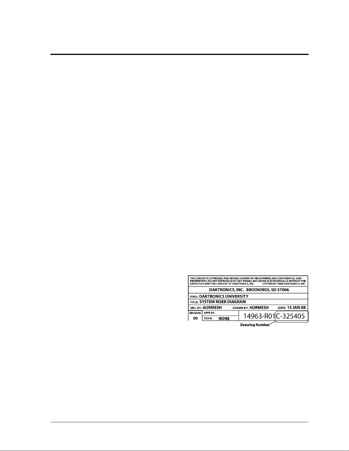
Figure 1: Daktronics Drawing Label
Section 1: Introduction
This manual explains the installation of Daktronics multi-section outdoor LED scoreboards and
provides details for maintenance and troubleshooting. For additional information regarding the
safety, installation, operation, or service of this system, refer to the telephone numbers listed in
Section 7. This manual is not specific to a particular installation.
Important Safeguards:
Please read and understand all instructions before beginning the installation process.
Do not drop control equipment or allow it to get wet.
Do not disassemble control equipment or electronic controls of the display; failure to
follow this safeguard will make the warranty null and void.
Disconnect display power when not in use or when servicing.
Disconnect display power before servicing power supplies to avoid electrical shock.
Power supplies run on high voltage and may cause physical injury if touched while
powered.
Do not modify the scoreboard structure or attach any panels or coverings to the
scoreboard without the express written consent of Daktronics, Inc.
Project-specific information takes precedence over any other general information found in
this manual.
1.1 Resources
Figure 1 illustrates a Daktronics drawing
label. The drawing number is located in the
lower-right corner of a drawing. This
manual refers to drawings by listing the last
set of digits and the letter preceding them.
In the example, the drawing would be
referred to as Drawing C-325405.
Reference Drawing:
System Riser Diagram ........................................................................... Drawing C-325405
Daktronics identifies manuals by the DD or ED number located on the cover page of each
manual. For example, this manual would be referred to as ED-17610.
Introduction 1
Main Component Labels
Part Type
Part Number
Individual circuit board
0P-XXXX-XXXX
Assembly; a collection of circuit boards
0A-XXXX-XXXX
Wire or cable
W-XXXX
Fuse
F-XXXX
Transformer
T-XXXX
Metal part
M-XXX
Fabricated metal assembly
0S-XXXXXX
Specially ordered part
PR-XXXXX-X
Accessory Labels
Component
Label
Termination block for power
or signal cable
TBXX
Grounding point
EXX
Power or signal jack
JXX
Power or signal plug for the
opposite jack
PXX
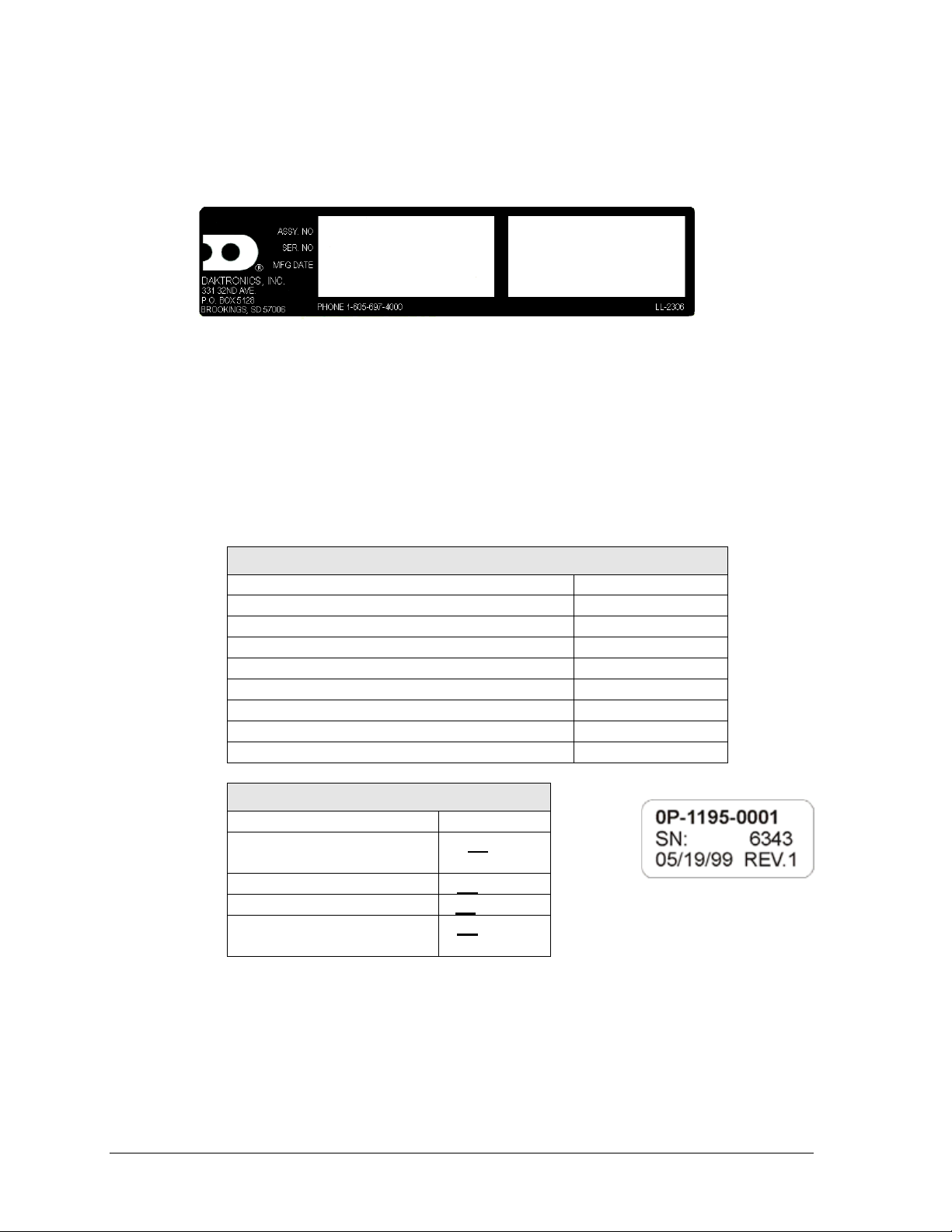
Figure 2: Scoreboard ID Label
Figure 3: Typical Label
1.2 Daktronics Nomenclature
Serial and model numbers can be found on the ID label on the display as shown in Figure 2.
Please list the model number, display serial number, and the date this display became
operational in the blanks provided on the second page of this manual. When calling
Daktronics customer service, please have this information available to ensure the request is
serviced as quickly as possible.
Most components within this display carry a white label that lists the part number of the unit.
If a component is not found in the Replacement Parts List in Section 5.13, use the label to
order a replacement. Figure 3 illustrates a typical label. The part number is in bold.
Following the Replacement Parts List is the Daktronics Exchange Policy and the Repair &
Return Program. Refer to these instructions if replacing or repairing any display component.
2 Introduction
BA
Baseball
-11
120 V, with red digits
FB
Football
-21
120 V, with amber digits
MS
Multisport
-12
240 V, with red digits
SO
Soccer
-22
240 V, with amber digits
-41
120 V, with white digits
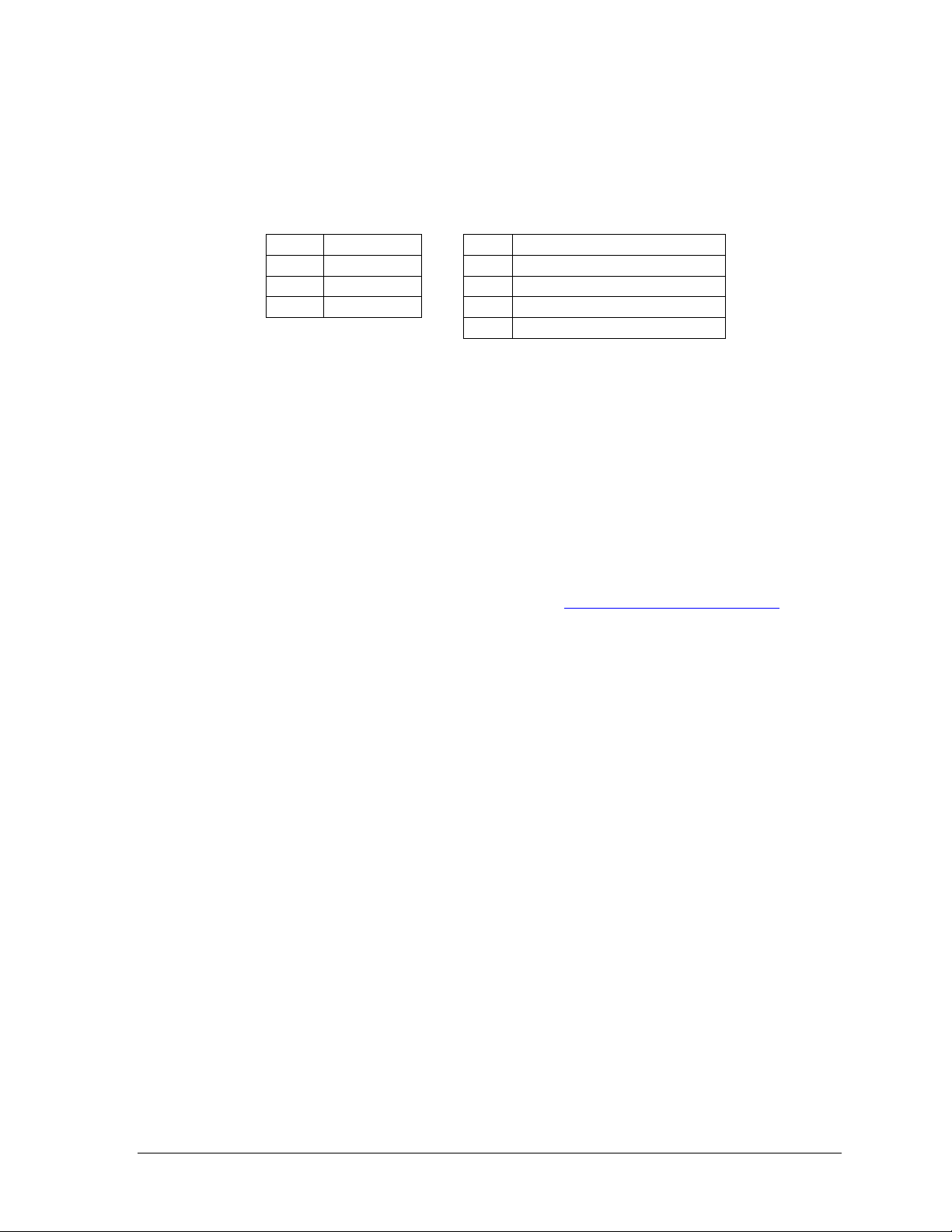
1.3 Model Number
Daktronics scoreboards are differentiated by their model numbers and two-letter prefixes for
each sport. Most Daktronics scoreboards also carry a two-number suffix that refers to the type
of power supply and digit color. Refer to the following tables:
1.4 Scoreboard Controllers
Daktronics outdoor scoreboards are designed for use with the All Sport® 5000 series control
consoles. Scoreboards with 5 or 6-digit clocks may also be controlled via the OmniSport® 2000
console for track timing. Both consoles use keyboard overlays (sport inserts) to control
numerous sports and scoreboard models. Refer to the following manuals for operating
instructions:
All Sport 5000 Series Control Console Operation Manual (ED-11976)
OmniSport 2000 Timing Console Operations Manual (ED-13312)
These control console manuals are available online at www.daktronics.com/manuals.
1.5 Product Safety Approval
Daktronics outdoor scoreboards are ETL listed and tested to CSA standard for outdoor use.
Contact Daktronics with any questions regarding testing procedures.
Introduction 3

Model &
Options
Number of
Sections
Dimensions:
Height, Width, Depth
Weight
Watts
Amps
120 / 240 V AC
Driver #
& Address
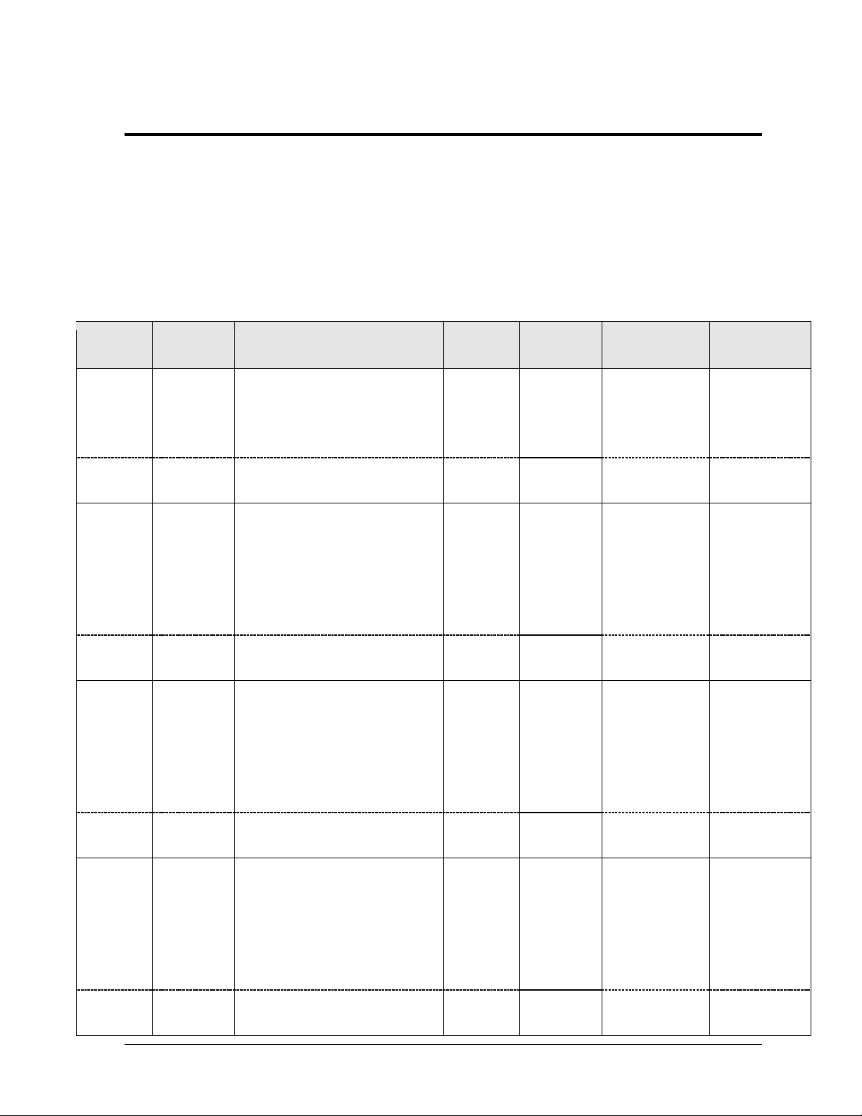
BA-1518
2 Total
Top &
Bottom
H 8'-0", W 16'-0", D 6"
(2438 mm, 4877 mm, 152 mm)
H 4'-0", W 16'-0", D 6"
(1219 mm, 4877 mm, 152 mm)
400 lb
(182 kg)
300 W
[450 W]
2.5 A / 1.25 A
[3.8 A / 1.9 A]
A1 63
w/TNMC
(same)
(same)
480 lb
(218 kg)
600 W
[750 W]
5 A / 2.5 A
[6.3 A / 3.1 A]
TNMC 221
BA-1524
2 Total
Top
Bottom
H 9'-0", W 16'-0", D 6"
(2743 mm, 4877 mm, 152 mm)
H 4'-0", W 16'-0", D 6"
(1219 mm, 4877 mm, 152 mm)
H 5'-0", W 16'-0", D 6"
(1524 mm, 4877 mm, 152 mm)
450 lb
(204 kg)
300 W
[600 W]
2.5 A / 1.25 A
[5 A / 2.5 A]
A1 63
w/TNMC
(same)
(same)
530 lb
(240 kg)
600 W
[900 W]
5 A / 2.5 A
[7.5 A / 3.75 A]
TNMC 221
BA-2013
4 Total
Top 2
Bottom 2
H 9'-4", W 36'-0", D 6"
(2845 mm, 10973 mm, 152 mm)
H 4'-0", W 18'-0", D 6"
(1219 mm, 5486 mm, 152 mm)
H 5' -4", W 18'-0", D 6"
(1626 mm, 5486 mm, 152 mm)
840 lb
(382 kg)
1500 W
12.5 A / 6.25 A
A1 64
A2 65
A3 66
A4 01
A5 01
w/TNMC
(same)
(same)
960 lb
(436 kg)
1800 W
15 A / 7.5 A
TNMC 221
BA-3718
4 Total
Top 2
Bottom 2
H 7'-0", W 28'-0", D 6"
(2134 mm, 8534 mm, 152 mm)
H 3'-0", W 14'-0", D 6"
(914 mm, 4267 mm, 152 mm)
H 4' -0", W 14'-0", D 6"
(1219 mm, 4267 mm, 152 mm)
640 lb
(291 kg)
900 W
7.5 A / 3.75 A
A1 64
A2 65
A3 66
w/TNMC
(same)
(same)
720 lb
(327 kg)
1200 W
10 A / 5 A
TNMC 221
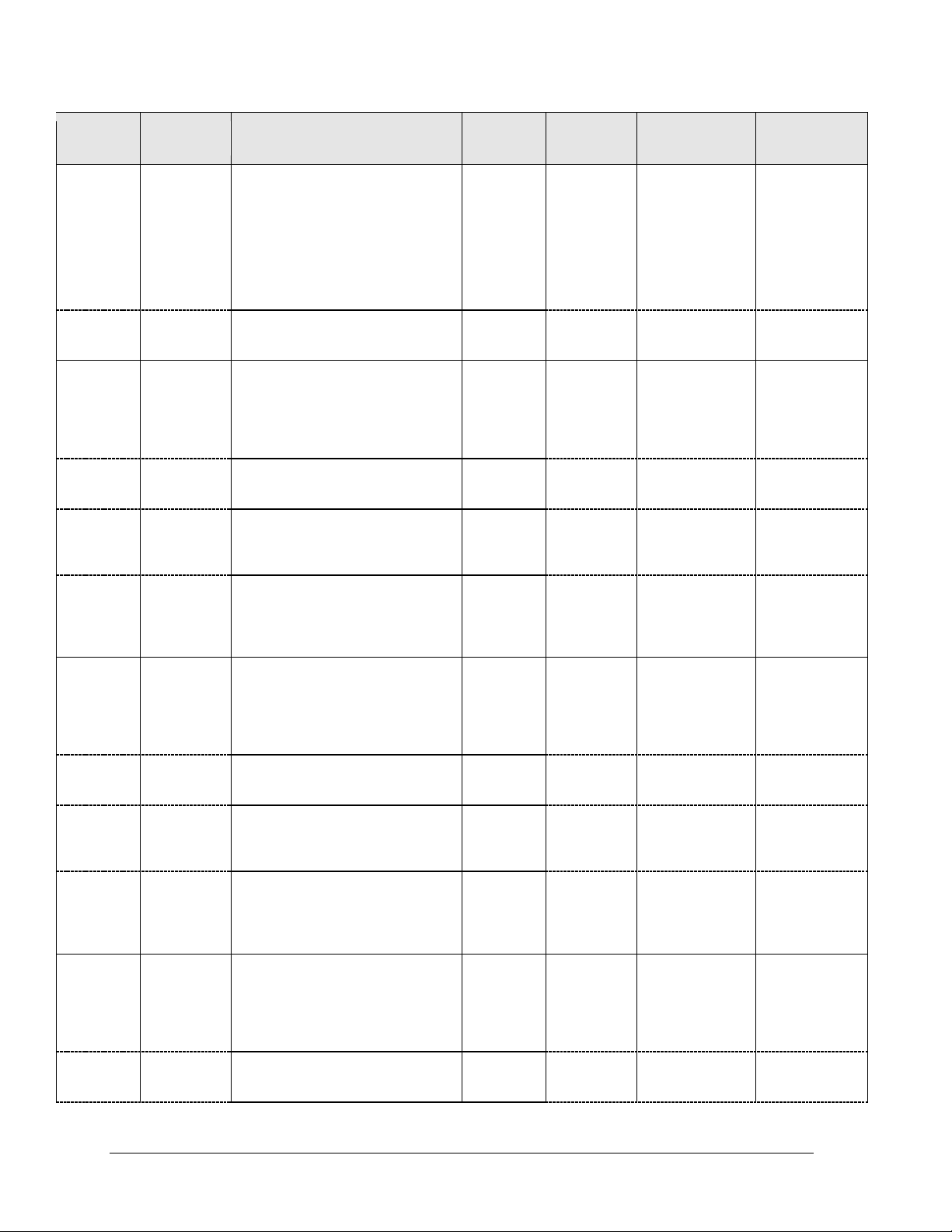
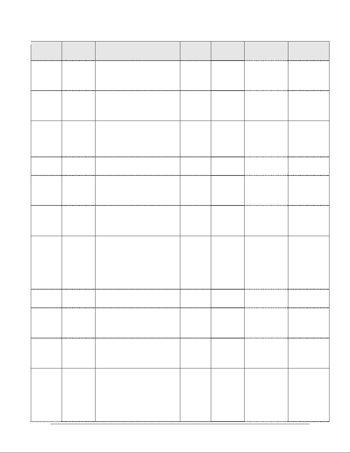
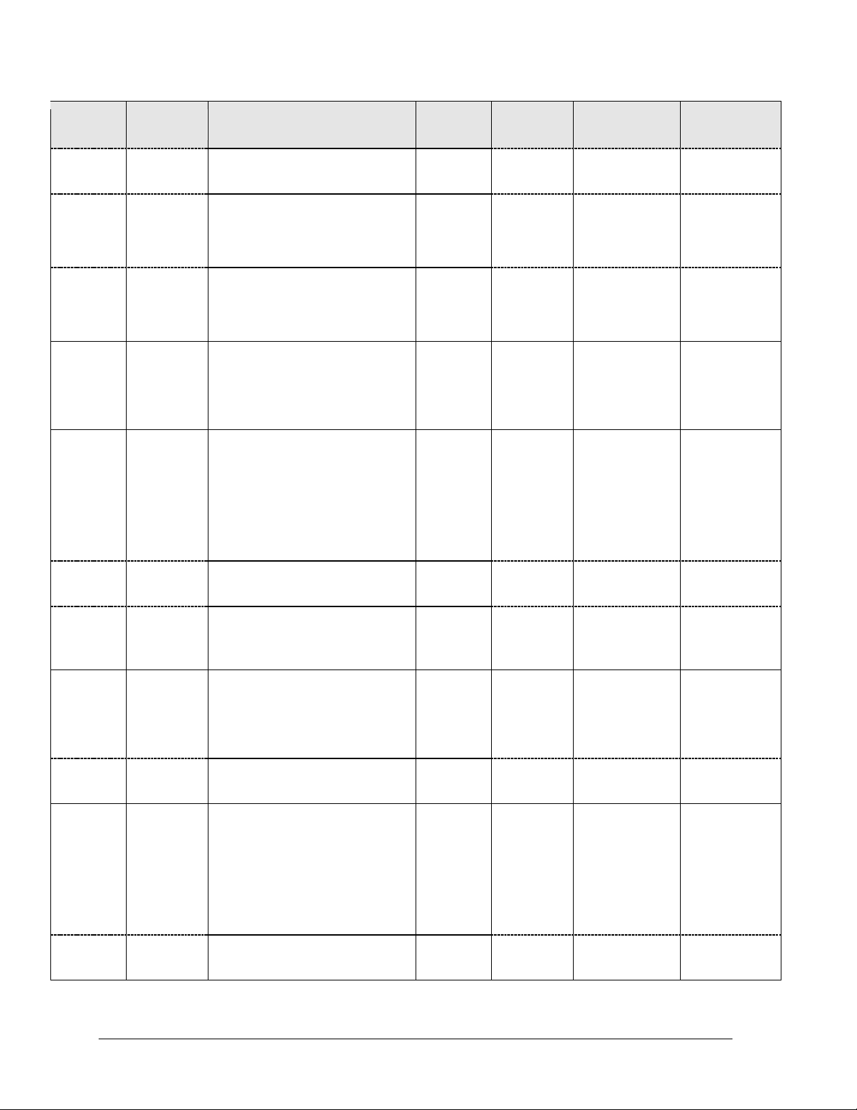
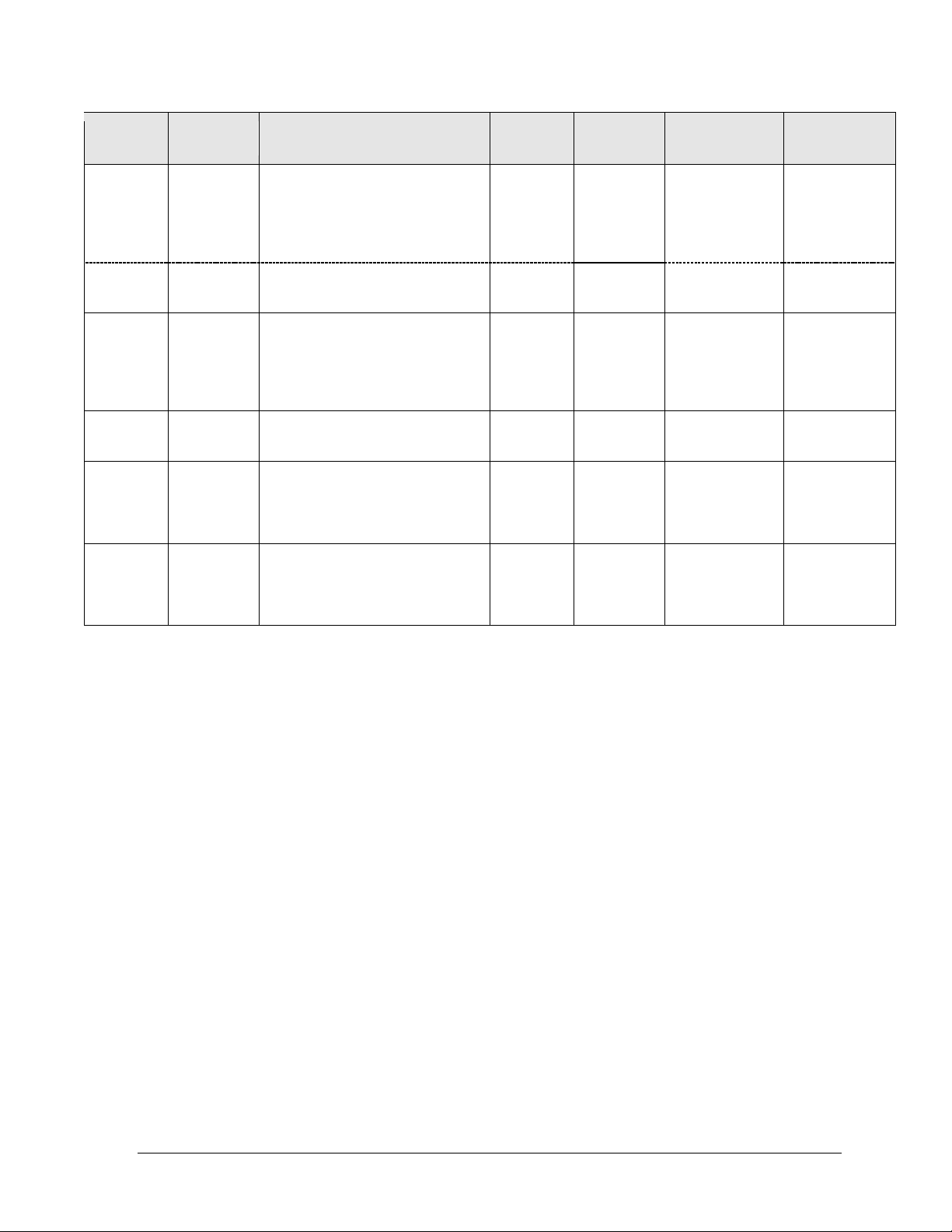
Section 2: Specifications
The chart on the following pages details all of the mechanical specifications, circuit specifications and
power requirements for each display in this manual. Models are listed in alphanumeric order.
Notes:
1) All displays require a 120 V AC, 15 A circuit; 240 V AC power also available
2) TNMC and electronic caption LEDs are typically the same color as the LED digits on the
scoreboard. Backlit captions use 120 V AC circular florescent bulbs.
3) Watts and Amps in [brackets] indicate separate power specs for white LED digits.
Specifications 5
Model &
Options
Number of
Sections
Dimensions:
Height, Width, Depth
Weight
Watts
Amps
120 / 240 V AC
Driver #
& Address
BA-3724
4 Total
Top 2
Bottom 2
H 9'-4", W 36'-0", D 6"
(2845 mm, 10973 mm, 152 mm)
H 4'-0", W 18'-0", D 6"
(1219 mm, 5486 mm, 152 mm)
H 5'-4", W 18'-0", D 6"
(1626 mm, 5486 mm, 152 mm)
840 lb
(382 kg)
900 W
7.5 A / 3.75 A
A1 64
A2 65
A3 66
w/TNMC
(same)
(same)
960 lb
(436 kg)
1200 W
10 A / 5 A
TNMC 221
FB-2018
FB-2019
FB-2020
2 Total
Top &
Bottom
H 8'-0", W 18'-0", D 6"
(2438 mm, 5486 mm, 152 mm)
H 4'-0", W 18'-0", D 6"
(1219 mm, 5486 mm, 152 mm)
565 lb
(256 kg)
600 W
5 A / 2.5 A
A1 15
A2 19
w/TNMC
(same)
(same)
645 lb
(293 kg)
900 W
7.5 A / 3.75 A
TNMC 221
w/TNMC +
Electronic
Captions
(same)
(same)
805 lb
(365 kg)
1200 W
10 A / 5 A
Electronic
Captions 227
w/Backlit
Captions
(Top &
Bottom)
(same)
(same)
625 lb
(283 kg)
1500 W
12.5 A
(120 V AC only)
A1 15
A2 19
FB-2021
FB-2022
FB-2023
2 Total
Top &
Bottom
H 8'-0", W 25'-0", D 6"
(2438 mm, 7620 mm, 152 mm)
H 4'-0", W 25-0", D 6"
(1219 mm, 7620 mm, 152 mm)
815 lb
(370 kg)
600 W
5 A / 2.5 A
A1 15
A2 19
w/TNMC
(same)
(same)
935 lb
(424 kg)
900 W
7.5 A / 3.75 A
TNMC 221
w/TNMC +
Electronic
Captions
(same)
(same)
1095 lb
(496 kg)
1200 W
10 A / 5 A
Electronic
Captions 227
w/Backlit
Captions
(Top &
Bottom)
(same)
(same)
875 lb
(396 kg)
1500 W
12.5 A
(120 V AC only)
A1 15
A2 19
FB-2024
2 Total
Top &
Bottom
H 8'-0", W 32'-0", D 6"
(2438 mm, 9754 mm, 152 mm)
H 4'-0", W 32'-0", D 6"
(1219 mm, 9754 mm, 152 mm)
720 lb
(327 kg)
600 W
5 A / 2.5 A
A1 15
A2 19
w/TNMC
(same)
(same)
840 lb
(381 kg)
900 W
7.5 A / 3.75 A
TNMC 221
6 Mechanical Installation
Model &
Options
Number of
Sections
Dimensions:
Height, Width, Depth
Weight
Watts
Amps
120 / 240 V AC
Driver #
& Address
w/TNMC +
Electronic
Captions
(same)
(same)
1080 lb
(489 kg)
1200 W
10 A / 5 A
Electronic
Captions 227
T.O.L. 225
w/Backlit
Captions
(Top &
Bottom)
(same)
(same)
800 lb
(362 kg)
1500 W
12.5 A
(120 V AC only)
A1 15
A2 19
FB-2025
2 Total
Top &
Bottom
H 8'-0", W 32'-0", D 6"
(2438 mm, 9754 mm, 152 mm)
H 4'-0", W 32'-0", D 6"
(1219 mm, 9754 mm, 152 mm)
780 lb
(353 kg)
600 W
5 A / 2.5 A
A1 15
A2 19
w/TNMC
(same)
(same)
900 lb
(408 kg)
900 W
7.5 A / 3.75 A
TNMC 221
w/TNMC +
Electronic
Captions
(same)
(same)
1140 lb
(517 kg)
1200 W
10 A / 5 A
Electronic
Captions 227
T.O.L. 225
w/Backlit
Captions
(Top &
Bottom)
(same)
(same)
860 lb
(390 kg)
1500 W
12.5 A
(120 V AC only)
A1 15
A2 19
FB-2026
2 Total
Top
Bottom
H 10'-0", W 32'-0", D 6"
(3048 mm, 9754 mm, 152 mm)
H 6'-0", W 32'-0", D 6"
(1829 mm, 9754 mm, 152 mm)
H 4'-0", W 32'-0", D 6"
(1219 mm, 9754 mm, 152 mm)
880 lb
(400 kg)
600 W
5 A / 2.5 A
A1 15
A2 19
w/TNMC
(same)
(same)
1000 lb
(454 kg)
900 W
7.5 A / 3.75 A
TNMC 221
w/TNMC +
Electronic
Captions
(same)
(same)
1240 lb
(562 kg)
1200 W
10 A / 5 A
Electronic
Captions 227
T.O.L. 225
w/Backlit
Captions
(Top &
Bottom)
(same)
(same)
940 lb
(426 kg)
1500 W
12.5 A
(120 V AC only)
A1 15
A2 19
FB-2027
2 Total
Top
Bottom
H 10'-0", W 32'-0", D 6"
(3048 mm, 9754 mm, 152 mm)
H 6'-0", W 32'-0", D 6"
(1829 mm, 9754 mm, 152 mm)
H 4'-0", W 32'-0", D 6"
(1219 mm, 9754 mm, 152 mm)
940 lb
(426 kg)
600 W
5 A / 2.5 A
A1 15
A2 19
Specifications 7
Model &
Options
Number of
Sections
Dimensions:
Height, Width, Depth
Weight
Watts
Amps
120 / 240 V AC
Driver #
& Address
w/TNMC
(same)
(same)
1060 lb
(481 kg)
900 W
7.5 A / 3.75 A
TNMC 221
w/TNMC +
Electronic
Captions
(same)
(same)
1300 lb
(590 kg)
1200 W
10 A / 5 A
Electronic
Captions 227
T.O.L. 225
w/Backlit
Captions
(Top &
Bottom)
(same)
(same)
1020 lb
(462 kg)
1500 W
12.5 A
(120 V AC only)
A1 15
A2 19
FB-3010
w/TNMC
2 Total
Top &
Bottom
H 8'-0", W 18'-0", D 6"
(2438 mm, 5486 mm, 152 mm)
H 4'-0", W 18'-0", D 6"
(1219 mm, 5486 mm, 152 mm)
600 lb
(272 kg)
1200 W
5 A
(240 V AC only)
A1 1
A2 11
TNMC 221
MS-2009
2 Total
Top
Bottom
H 10’-0”, W 25’-0”, D 6”
(3048 mm, 7620 mm, 152 mm)
H 4’-6”, W 25’-0”, D 6”
(1371 mm, 7620 mm, 152 mm)
H 5’-6”, W 25’-0”, D 6”
(1676 mm, 7620 mm, 152 mm)
770 lb
(349 kg)
600 W
5 A / 2.5 A
A1 71
A2 72
w/TNMC
(same)
(same)
890 lb
(404 kg)
900 W
7.5 A / 3.75 A
TNMC 221
w/TNMC +
Electronic
Captions
(same)
(same)
1130 lb
(513 kg)
1200 W
10 A / 5 A
Electronic
Captions 223
MS-2918
2 Total
Top &
Bottom
H 8’-0”, W 16’-0”, D 6”
(2438 mm, 4877 mm, 152 mm)
H 4’-0”, W 16’-0”, D 6”
(1219 mm, 4877 mm, 152 mm)
480 lb
(218 kg)
600 W
5 A / 2.5 A
A1 71
A2 72
w/TNMC
(same)
(same)
560 lb
(254 kg)
900 W
7.5 A / 3.75 A
TNMC 221
SO-2011
2 Total
Top
Bottom
H 7'-0", W 20'-0", D 6"
(2286 mm, 6096 mm, 152 mm)
H 4'-6", W 20'-0", D 6"
(1372 mm, 6096 mm, 152 mm)
H 3'-0", W 20'-0", D 6"
(914 mm, 6096 mm, 152 mm)
450 lb
(204 kg)
600 W
5 A / 2.5 A
A1 17
A2 11
w/TNMC
(same)
(same)
570 lb
(259 kg)
900 W
7.5 A / 3.75 A
TNMC 221
8 Mechanical Installation
Model &
Options
Number of
Sections
Dimensions:
Height, Width, Depth
Weight
Watts
Amps
120 / 240 V AC
Driver #
& Address
SO-2018
SO-2019
2 Total
Top &
Bottom
H 8'-0", W 18'-0", D 6"
(2438 mm, 5486 mm, 152 mm)
H 4'-0", W 18'-0", D 6"
(1219 mm, 5486 mm, 152 mm)
565 lb
(256 kg)
600 W
5 A / 2.5 A
A1 15
A2 19
w/TNMC
(same)
(same)
645 lb
(293 kg)
900 W
7.5 A / 3.75 A
TNMC 221
SO-2021
SO-2022
SO-2023
2 Total
Top &
Bottom
H 8'-0", W 25'-0", D 6"
(2438 mm, 7620 mm, 152 mm)
H 4'-0", W 25'-0", D 6"
(1219 mm, 7620 mm, 152 mm)
815 lb
(370 kg)
600 W
5 A / 2.5 A
A1 15
A2 19
w/TNMC
(same)
(same)
935 lb
(424 kg)
900 W
7.5 A / 3.75 A
TNMC 221
w/TNMC +
Electronic
Captions
(same)
(same)
1095 lb
(496 kg)
1200 W
10 A / 5 A
Electronic
Captions 227
T.O.L. 225
w/Backlit
Captions
(Top &
Bottom)
(same)
(same)
875 lb
(396 kg)
1500 W
12.5 A
(120 V AC only)
A1 15
A2 19
Specifications 9

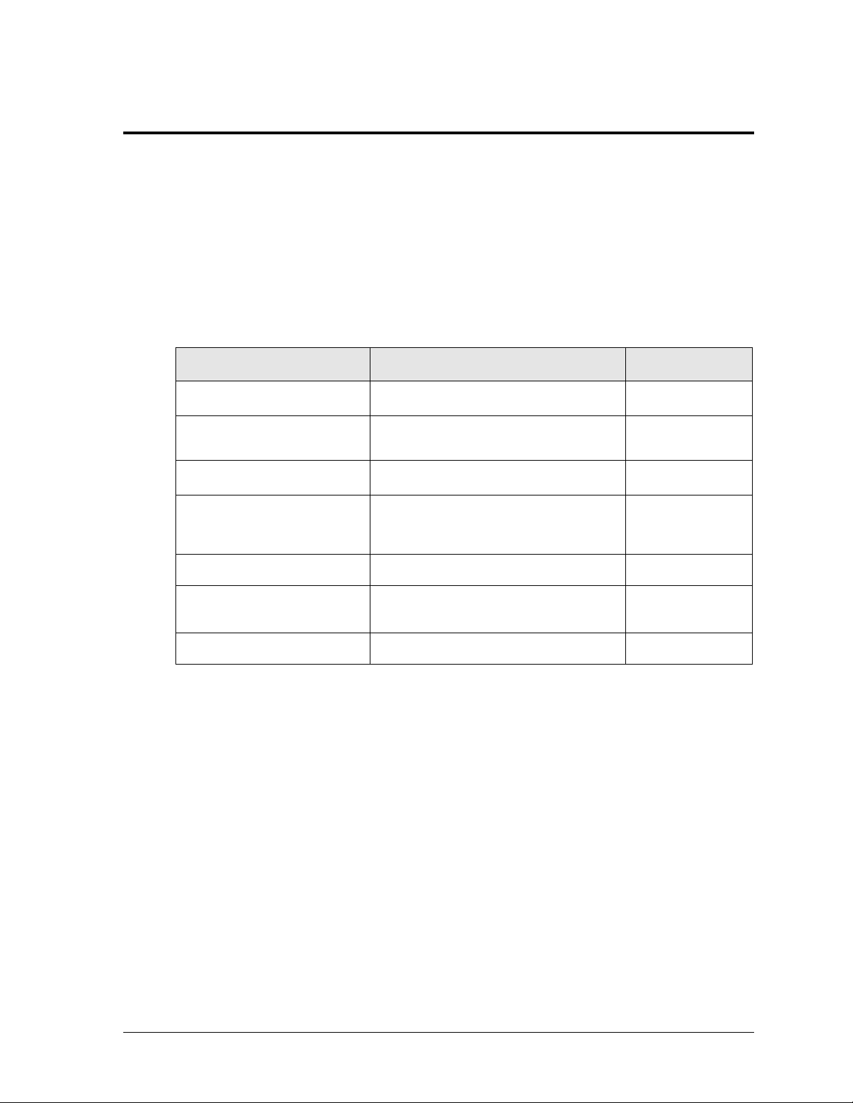
Models
Drawing Title
Number
BA-1518, BA-1524, MS-2918
16' Width Scoreboard Installation Specs
A-298975
FB-2018, FB-2019, FB-2020,
FB 3010, SO-2018, SO-2019
18' Width Scoreboard Installation Specs
A-302416
SO-2011
20' Width Scoreboard Installation Specs.
A-303616
FB-2021, FB-2022, FB-2023,
MS-2009, SO-2021, SO-2022,
SO-2023
25' Width Scoreboard Installation Specs
A-316750
BA-3718
28' Width Scoreboard Installation Specs
A-316971
FB-2024; FB-2025, FB-2026,
FB-2027
32' Width Scoreboard Installation Specs
A-317264
BA-3724, BA-2013
Installation Specifications, BA-3724
A-126445
Section 3: Mechanical Installation
Mechanical installation consists of installing concrete footing and steel beams and mounting the
scoreboard and accompanying ad panels to the beams.
3.1 Footings & Beams
The installation specification drawings listed in Appendix A show the recommended number
of beams and spacing between them. The drawings also indicate the size of beams required to
support the scoreboard at different heights and at various wind speeds. Use the following
table to determine which drawings provide the installation specifications for each model:
The column and footing size dimensions are to assist with estimating installation costs. They
are estimates only and are not intended for actual construction purposes. Be sure that the
installation complies with local building codes and is suitable for the particular soil and wind
conditions. The columns, footings, and all connection details must be designed and certified
by a professional engineer licensed to practice in the state of the scoreboard installation.
Note: Daktronics does not assume any liability for any installation derived from the
information provided in this manual or installations designed and installed by others.
3.2 Lifting the Scoreboard
Larger scoreboard sections and message centers are shipped equipped with eyebolts used to
lift them. The eyebolts are located along the top of the cabinet for each scoreboard or
scoreboard section. Daktronics scoreboards use 1/2" and 5/8" shoulder-type eyebolts mounted
to a 1/8" aluminum plate or steel nut plate.
Daktronics strongly recommends using a spreader bar, or lifting bar, to lift the display.
Spreader bars ensure the force on the eyebolts remains straight up, minimizing lifting stress.
Mechanical Installation 11
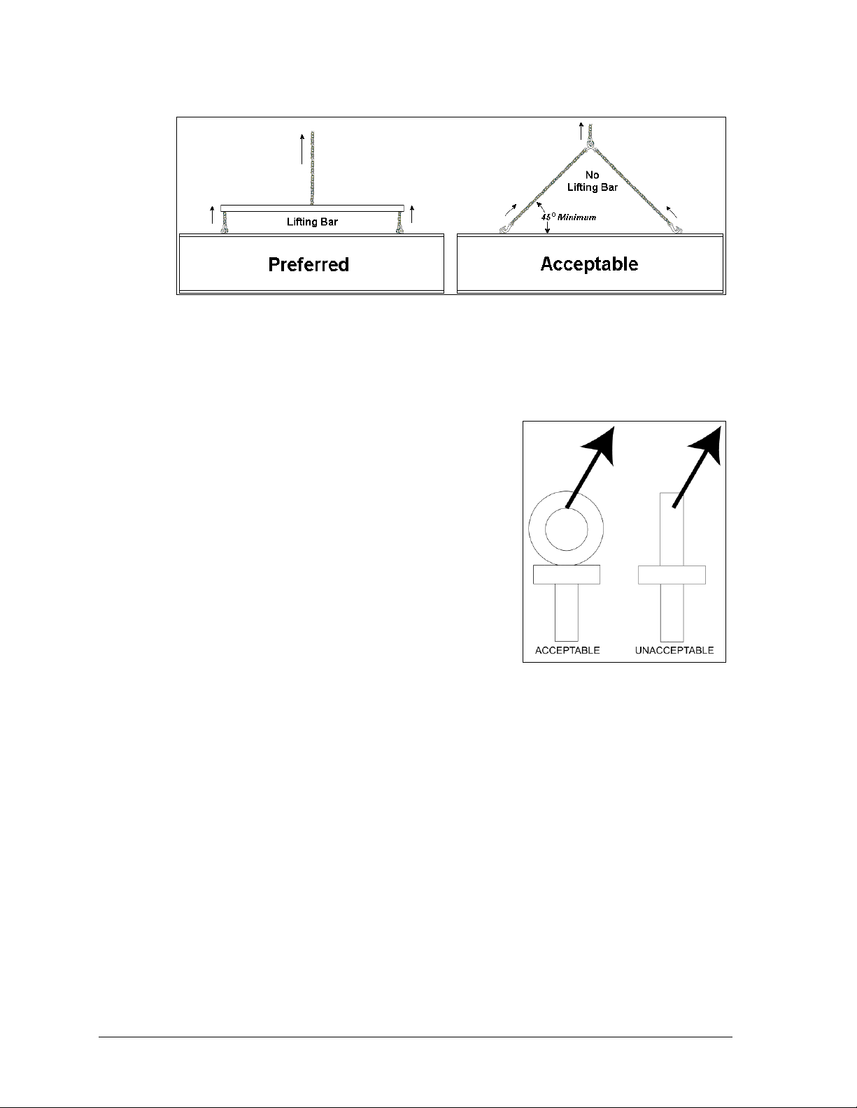
Figure 4: Lifting Methods
Figure 5: Eyebolt Plane Load
Figure 4 illustrates the preferred scoreboard lifting method on the left and an acceptable
alternative lifting method on the right. When lifting the display:
Use a spreader bar if possible.
Use every lifting point provided.
Cables and chains attached to the eyebolts and directly to
a center lifting point, as shown in the right-hand example
in Figure 4, can create a dangerous lateral force on the
eyebolts and may cause the eyebolts to fail. The smaller
the angle between the cable and the top of the display, the
lighter the sign must be to safely lift it. If this method
must be used, ensure a minimum angle between the chain
and scoreboard of at least 45 degrees.
Do NOT attempt to lift the display if the angle is less than
45 degrees. Exceeding load angles or weight limits could
cause the bolts in the scoreboard cabinet to buckle,
resulting in serious damage to the scoreboard or injury to
personnel. Also, loads should be applied directly in the
plane of the eyebolt as shown in Figure 5.
Note: Daktronics assumes no liability for damages resulting from incorrect setup or
lifting methods. Eyebolts are intended for lifting only. Do not attempt to permanently
support the display by the eyebolts.
In typical multi-section installations, the lower scoreboard is installed first and secured to the
support beams. The upper section is then placed atop or above the lower section and attached
to the beams. There may be cables extending from the top of the lower section. Guide these
cables into the hole in the bottom of the upper section for later connection. Refer to Section
4.5 for more information on the power/signal connections between sections.
If installers remove the eyebolts, plug the holes with bolts and the rubber washers that are
used with the eyebolts. Apply silicone or another waterproof sealant to the eyebolt openings.
Also inspect the top and sides of the display for any other holes or openings that may allow
moisture to enter the display and plug and seal those openings.
12 Mechanical Installation
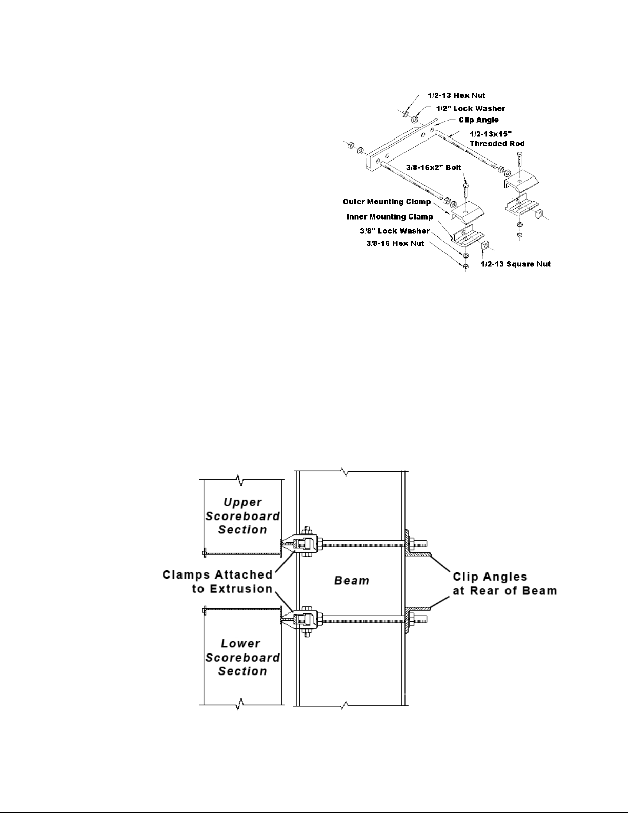
Figure 6: Mounting Hardware
Figure 7: Clamp Mounting Method, Side View
3.3 Scoreboard Mounting
Mounting hardware includes inner and
outer mounting clamps; clip angles; 1/2-13 x
15" threaded rods; 3/8-16 x 2" bolts, hex nuts
and lock washers; and 1/2" square nuts, hex
nuts, and lock washers. Refer to Figure 6 or
Drawing A-308051 in Appendix A. Each
section of the scoreboard attaches at the top
and the bottom to every beam.
Note: The threaded rods do not pass
through the flanges of the beams, but
instead run along both sides.
1. Using
2. Insert a
3. Position the scoreboard at the front of the beams with the threaded rods extending
4. Slide clip angles over the ends of the rods and loosely install the washers and nuts.
5. Make final adjustments in the positioning of the scoreboard. Tighten the
6. Make sure that the threaded rods are perpendicular to the scoreboard, and tighten all
3
/8" bolts, loosely attach the
inner and outer mounting clamps to
the rear flanges of the scoreboard.
Measure the beam spacing and position the clamps to fit on either side of the beams.
1
/2" square nut into each mounting clamp. Screw a threaded rod into each of
the nuts from the rear.
from the rear of the clamps, straddling the beams. Raise the scoreboard section to the
desired height.
the mounting clamps.
of the 1/2" hex nuts (Figure 7).
3
/8" bolts in
Mechanical Installation 13
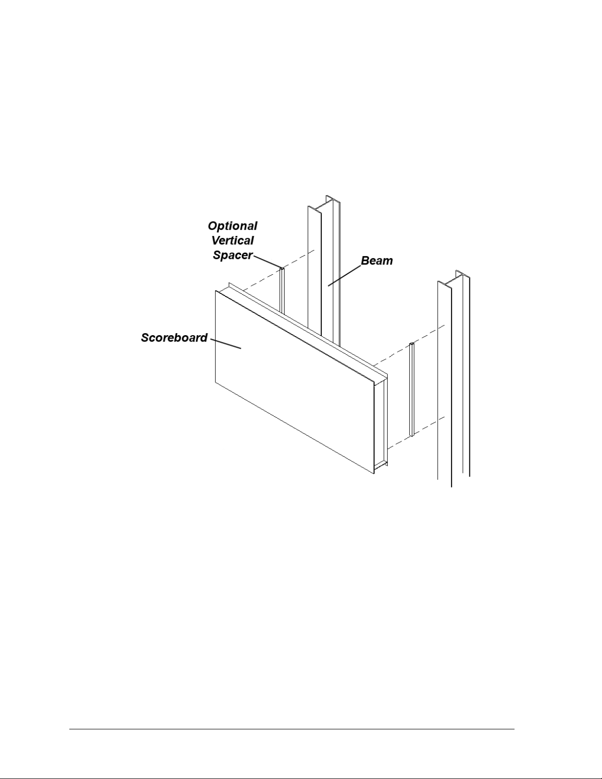
Figure 8: Mounting with Vertical Spacers
Scoreboard Mounting Using Vertical Spacers
Many customers add message centers or advertising panels to the top or bottom of their
scoreboards, and in some cases the depth of the add-on component may not match the depth
of the scoreboard. This will typically be scoreboards that are 8" deep.
To create a uniform appearance for the overall display, Daktronics recommends using
vertical spacers behind the scoreboard so that the front face of the display lines up evenly
with the front face of the added component. The concept is illustrated in Figure 8 and
Drawing A-182909 in Appendix A.
During the installation, spacers are placed between the mounting beams and the back of the
scoreboard cabinet. Spacer size is determined by the height and the extra depth required for
the front surface of the scoreboard to match that of the optional message center or ad panel.
Note: Daktronics does not provide these spacers.
3.4 Scoreboard Protective Devices
Daktronics makes optional protective devices, including screens and netting, to help prevent
damage to the scoreboard due to normal ball impacts.
Note: Some users install devices to protect the scoreboard from projectiles. Scoreboard
protection devices not provided by Daktronics must be approved by Daktronics prior to
installation. Failure to follow this approval procedure will void the scoreboard warranty.
14 Mechanical Installation
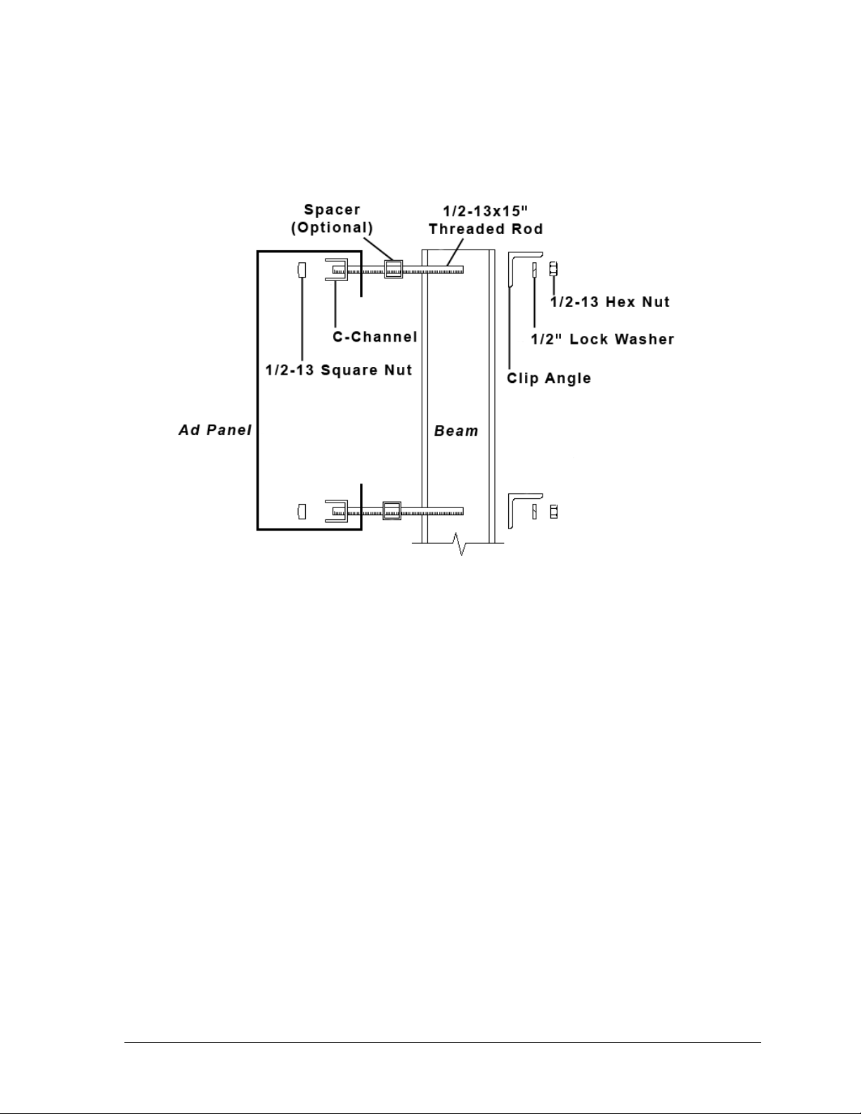
Figure 9: Ad Panel Mounting with C-channel, Side View
3.5 Ad Panel Mounting
The installation uses C-channels; clip angles; 1/2-13" threaded rods; and 1/2" square nuts, hex
nuts, lock washers, and optional spacers. Refer to Figure 9 and Drawing A-52187 in
Appendix A.
Mount the ad panel(s) as follows:
1. Use the width of the beam to determine which hole combination to use for the bolts.
Be sure to keep the bolts as close to the beam as possible.
2. Using the clip angle as a template, use a
9
/16" bit to drill holes in the upper and lower
rear flange of the ad panel where the C-channel supports will be placed.
3. Position the C-channel inside the ad panel cabinet along the upper and lower rear
flanges as shown in Figure 9.
4. Place 1/2" square nuts inside the channel and thread the 1/2-13" rods through the
C-channel, rear flange of the ad panel, and spacer (if used).
5. Lift the ad panel into position with the rods still in place.
6. With the threaded rod straddling the beams, place mounting angles over the ends of
each pair of bolts and secure with 1/2" lock washers and hex nuts.
7. Make final adjustments in the positioning of the ad panel.
8. Make sure that the threaded rods are perpendicular to the ad panel, and tighten all of
the 1/2" hex nuts.
Some ad panels have back sheets that must be removed before the display can be installed.
After marking and drilling holes in the upper and lower rear flanges of the ad panel, remove
the back sheets above and below the hole locations. Position the C-channel inside the cabinet
and attach the square nuts to the threaded rods as described above. Be sure to replace the
back sheets after placing the square nuts inside the channel and threading the rods through
the holes in both the upper and lower rear flanges.
Mechanical Installation 15

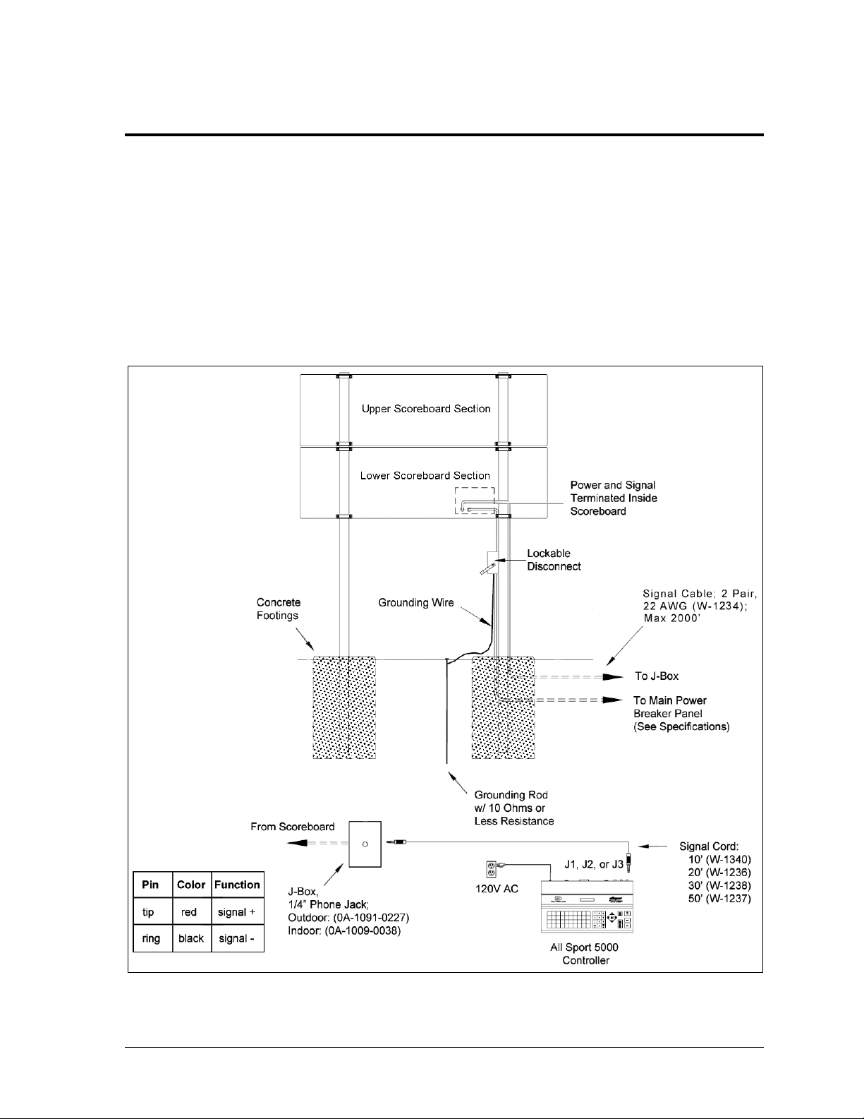
Figure 10: Wired Installation
Section 4: Electrical Installation
CAUTION: Only qualified individuals should terminate power and signal cable and access the
electrical components of the display and its associated equipment. It is the responsibility of the
electrical contractor to ensure that all electrical work meets or exceeds local and national codes.
Daktronics engineering staff must approve all changes or the warranty will be void.
4.1 Installation Overview
The diagram shown in Figure 10 illustrates a typical wired setup between a multi-section
outdoor scoreboard and controller. Daktronics part numbers are shown in parentheses.
Electrical Installation 17
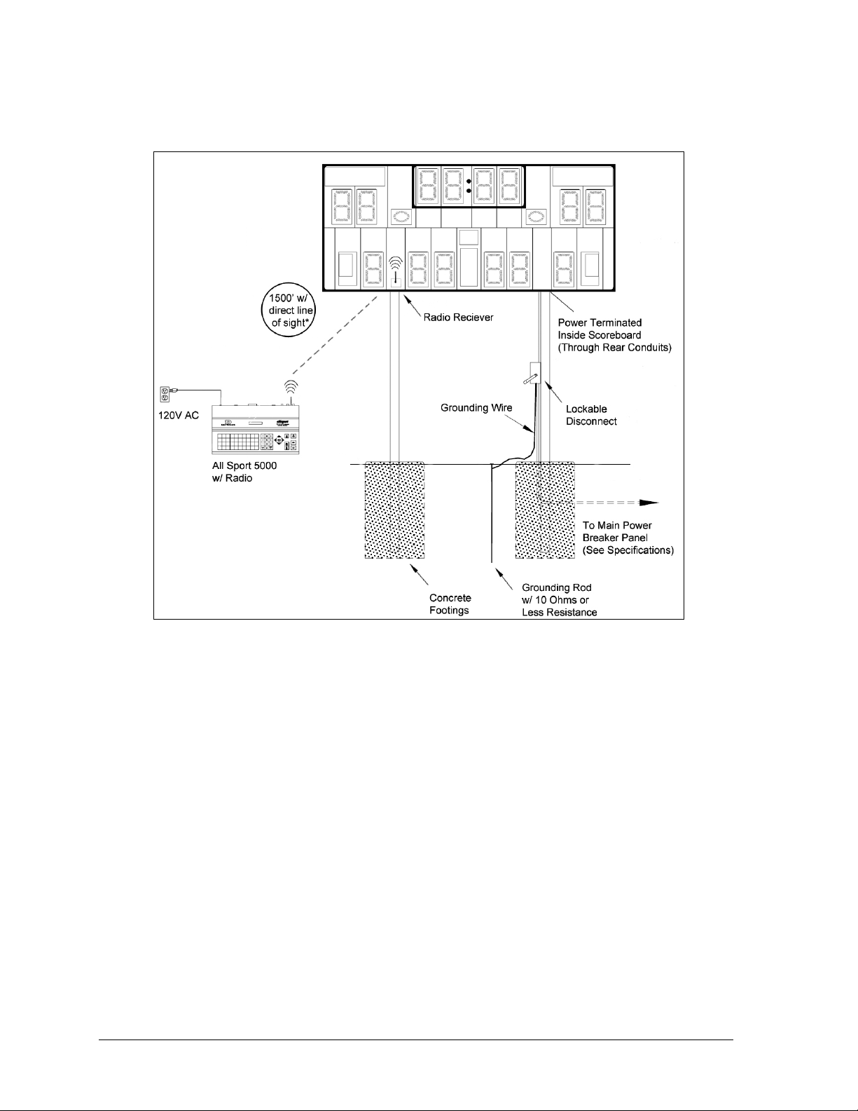
Figure 11: Wireless Installation
The diagram shown in Figure 11 illustrates a typical wireless setup between a multi-section
outdoor scoreboard and controller. Daktronics part numbers are shown in parentheses.
4.2 Power
Correct power installation is imperative for proper display operation. The subsections that
follow give details of display power installation. Only qualified individuals should attempt to
complete the electrical installation; untrained personnel should not attempt to install these
displays or any of the electrical components. Improper installation could result in serious
damage to the equipment or injury to personnel.
Multi-section outdoor scoreboards require a dedicated 120 V or 240 V circuit for incoming
power (refer to the Specifications in Section 2). The display itself has no breakers or fuses.
WARNING: It is critical that the scoreboard circuit be fused at 15 A and that all
conductors used must be designed to pass a 15 A current in normal operation.
Failure to meet wiring and overcurrent protection device requirements will void the
scoreboard warranty.
Grounding
The display must be properly grounded according to local and national codes or the warranty
will be void. Proper grounding is necessary for reliable equipment operation and protects the
equipment from damaging destructive disturbances and lightning.
18 Electrical Installation
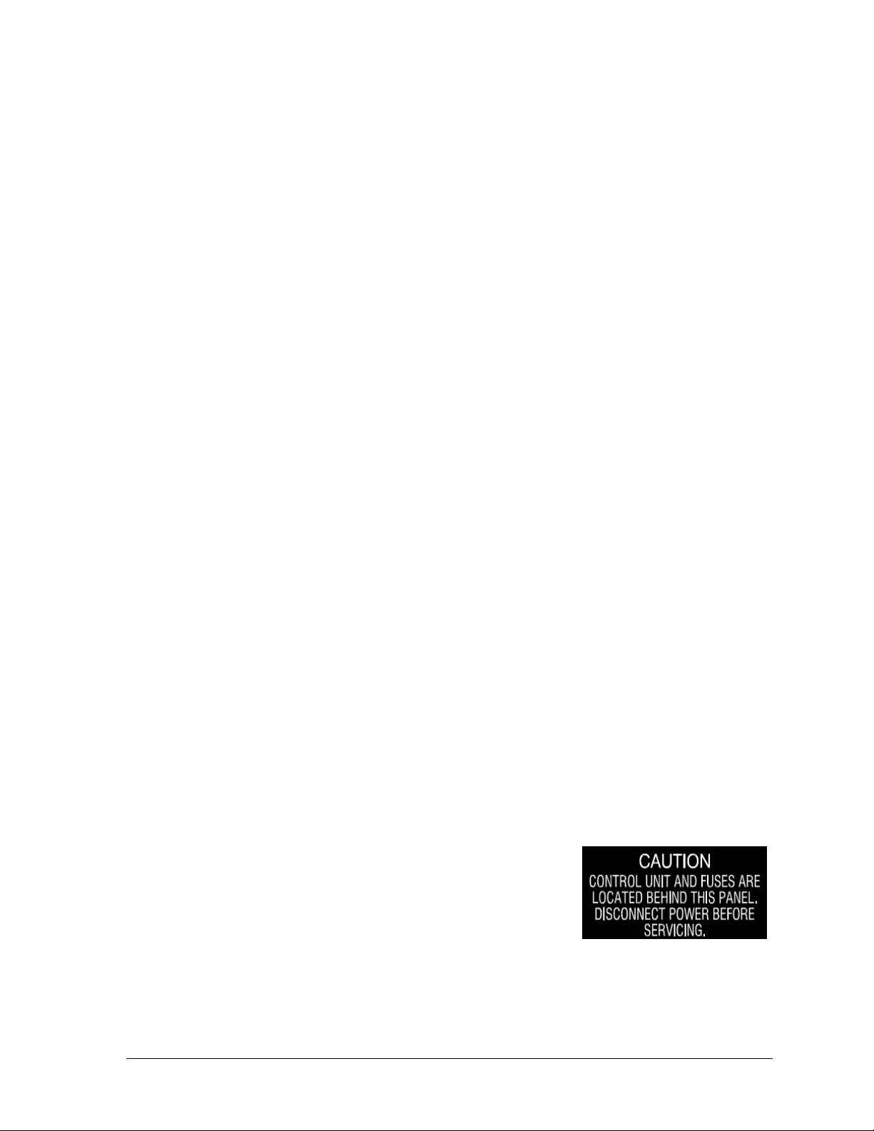
Figure 12: Power Warning Label
Daktronics recommends a resistance-to-ground of 10 ohms or less. The electrical contractor
performing the electrical installation can verify ground resistance. Daktronics Sales and
Service personnel can also provide this service.
The display system must be earth-ground. The material for an earth-ground electrode differs
from region to region and may vary according to conditions present at the site. Consult local
and national electrical codes.
Daktronics does not recommend using the support structure as an earth-ground electrode;
concrete, primer, corrosion, and other factors make the support structure a poor ground.
Note: The support structure may be used as an earth-ground electrode only if designed to do
so. A qualified inspector must approve the support structure and grounding methods.
There are two types of power installation: installation with ground and neutral conductors
provided, and installation with only a neutral conductor provided. These two power
installations differ slightly, as described in the following paragraphs:
Installation with Ground and Neutral Conductors Provided
For this type of installation, the power circuit must contain an isolated earth-ground
conductor. In this circumstance, do not connect neutral to ground at the disconnect or at the
display as this would violate electrical codes and void the warranty.
Use a disconnect so that all ungrounded lines can be disconnected. The National Electrical
Code requires the use of a lockable power disconnect within sight of or at the display.
Installation with Only a Neutral Conductor Provided
Installations where no grounding conductor is provided must comply with Article 250-32 of
the National Electrical Code. If the installation in question meets all of the requirements of
Article 250-32, the following guidelines must be observed:
Connect the grounding electrode cable at the local disconnect, never at the display
driver/power enclosure.
Use a disconnect that opens all of the ungrounded phase conductors.
Connection
Both power and signal cables are routed into the scoreboard from the rear through two
plastic plugs for conduit connection. All power and signal wiring terminates at the master
driver enclosure. Note that systems with radio control do not require external signal wiring.
Look for a warning label similar to Figure 12 to locate the
front access panel to the driver enclosure. Remove the screws
or loosen the latches to open the access door panel. Remove
the metal cover of the driver enclosure to expose the driver
components (Figure 13).
Refer to the component location drawings in Appendix A for
precise power/signal termination location for each model.
Electrical Installation 19
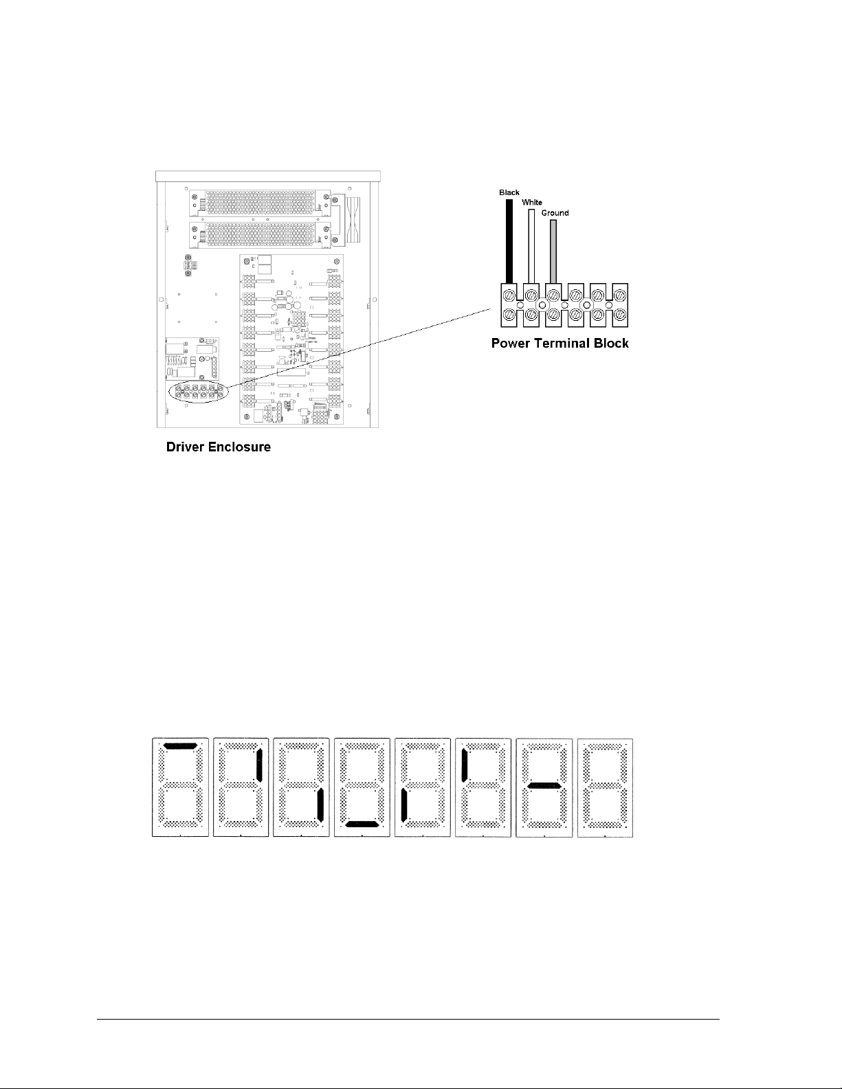
Figure 13: Driver Enclosure & Power Terminal Block
Figure 14: Digit Segment POST
Connect the appropriate wires coming through the rear of the scoreboard to the power
terminal block, as shown in Figure 13.
Note: If a power receptacle is needed to operate the control console at the scoreboard for
troubleshooting, Daktronics recommends that an installation electrician provides a 120 V
outlet close to the disconnect box specifically for this purpose.
4.3 Power-On Self-Test (POST)
The scoreboard performs a self-test each time that power is turned on and the control console
is powered off or not attached to the scoreboard. If the control console is attached and
powered on, the self-test does not run, and data from the control console is displayed on the
scoreboard after a brief period of time. Each scoreboard self-test pattern will vary depending
on the scoreboard model, the number of drivers and types of digits. Figure 14 shows an
example of the LED bar test pattern that each digit performs.
Radio Settings
If a radio receiver is installed, the radio Broadcast and Channel settings will be displayed in
the Home and Guest or clock digits during the POST. These values must match the settings in
the control console (refer to the manual listed in Section 1.4). Refer to Section 5.9 for more
information on radio installations.
20 Electrical Installation
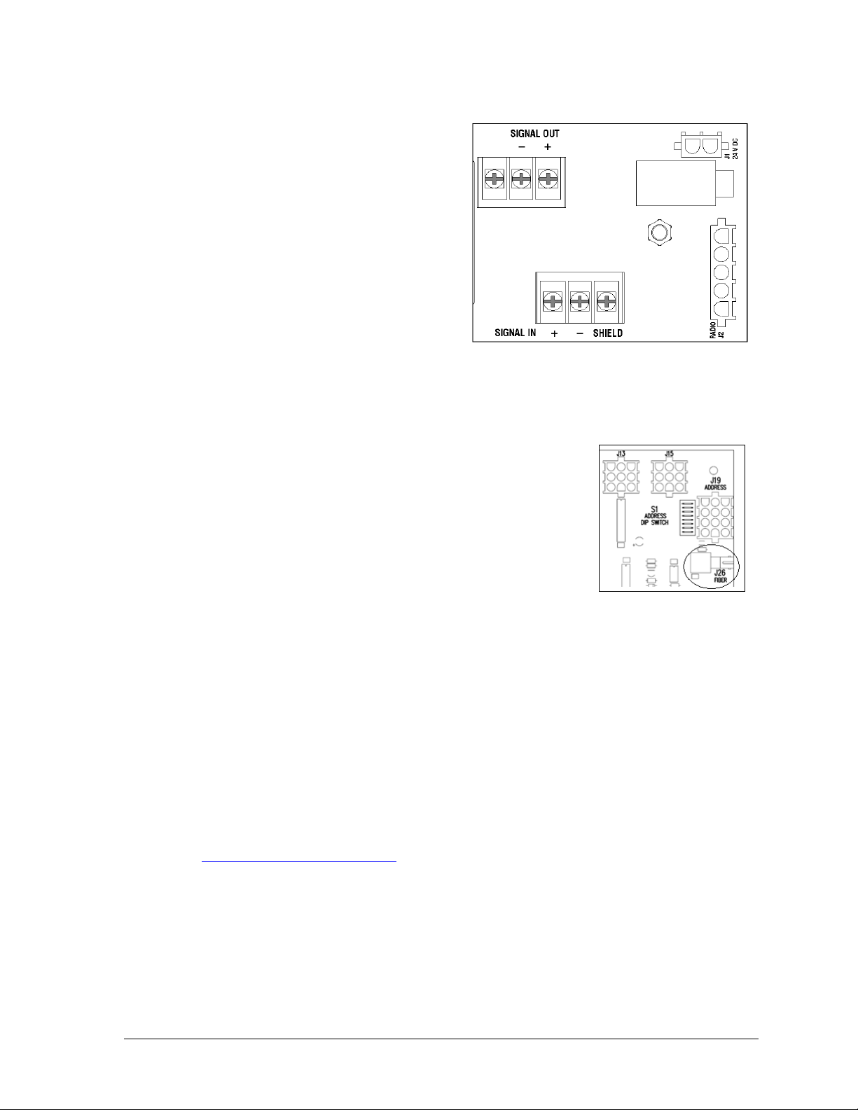
Figure 15: Signal Surge Arrestor Card
Figure 16: Driver Fiber
Connection Location
4.4 Signal Connection
For wired setups, route signal cable through
the conduit knockout on the rear of the
scoreboard to the signal surge arrestor card
(Figure 15), located just above the power
termination block in the driver enclosure.
At the SIGNAL IN terminal block, connect
the red signal wire to the positive terminal
and the black wire to the negative terminal.
Note: Be sure to properly connect the
shield (silver) wire to the SHIELD
terminal.
For signal cable, Daktronics recommends, as a minimum, single-pair, shielded cable, 22 AWG
(part number W-1077). Two-pair shielded cable (part number W-1234) is preferred.
Fiber Optic
Another common signal communication method is fiber optic
cabling. A minimum cabling of multi-mode, 62.5/125 um, and
2-core fiber cable is recommended (part number W-1242).
See Figure 16 for the location of the fiber connector on a 16column driver. This method requires a signal converter between
the All Sport console‟s scoreboard output and the fiber optic cable
(not provided by Daktronics).
Multiple Driver Connections
Some models in the multi-section outdoor scoreboard line require multiple drivers in each
scoreboard section, and use a master/slave driver system. Master and slave drivers function
identically, but slave units lack the power termination block and signal surge suppression
card. When one section has multiple drivers, they simply plug into one another, and this is
done at the factory. Drivers between sections, however, require additional on-site connection
as described in Section 4.5.
Note: Scoreboards capable of displaying speed of pitch (SOP) have an additional master
driver. These models also require a separate signal connection (either wired or radio)
from a dedicated speed of pitch All Sport 5000 console. Refer to the Baseball Speed of
Pitch Systems Configuration Manual (ED-12224), available online at
www.daktronics.com/manuals, for more information about setting up an SOP system.
4.5 Power/Signal Connections Between Sections
Most multi-section outdoor scoreboards use a single power/signal interconnect cable
between a driver in the upper section and a driver in the lower section (Figure 17).
It is common for the top driver to be located behind the right-most HOME score digit with
the bottom driver located behind the right-most digit of the left-most set of digits. Refer to the
component location drawings in Appendix A for exact driver locations.
Electrical Installation 21
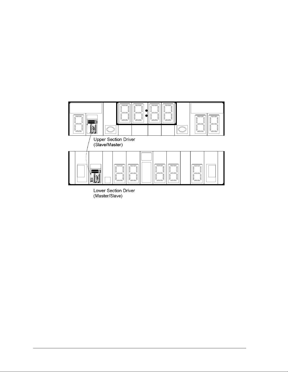
Figure 17: Typical Upper/Lower Scoreboard Section Connection (Digits Removed to Show Drivers)
1. On the upper section, open the appropriate access panel to locate the bundle of
interconnect cable coming from the driver.
Note: Additional panels may be opened for easier access when routing the cable.
2. Route the interconnect cable through the hole in the bottom of the upper cabinet
through the hole in the top of the lower cabinet, and plug it into the driver.
If the lower section contains the master driver, the harness will connect to J42.
If the lower section contains the slave driver, the harness will connect to P43.
3. With four-section scoreboards, be sure to also connect any plugs extending from the
right side of the left cabinets to the corresponding jacks on the left side of the right
cabinets.
Note: Similar connections exist between the upper and lower cabinets of multisection, single-driver scoreboards as well.
4.6 Lightning Protection
The use of a disconnect near the scoreboard to completely cut all current-carrying lines
significantly protects the circuits against lightning damage. In order for this system to
provide protection, the power must be disconnected when the scoreboard is not in use.
The control console should also be disconnected from power and from the signal junction box
when the system is not in use. The same surges that may damage the scoreboard‟s driver can
also damage the console‟s circuitry.
22 Electrical Installation
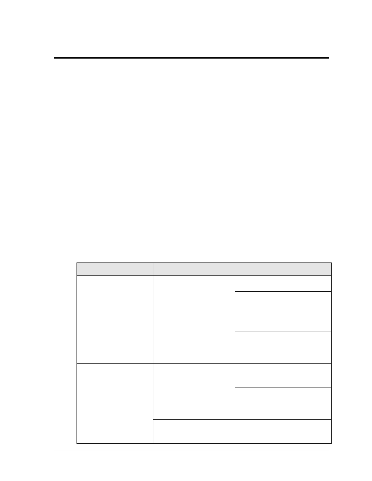
Problem
Possible Cause
Solution/Items to Check
Scoreboard doesn’t light
and console doesn’t work
No power to the scoreboard
Check that the main circuit breaker
for the scoreboard is on.
Check that the scoreboard is
receiving the correct 120 (or 240) V
AC power (see Section 2).
No power to console
Ensure the console is plugged into a
120 (or 240) V AC power supply.
Swap the console with one known to
work correctly, and enter the proper
sport code and/or radio settings to
test. Replace console if necessary.
Scoreboard digits don’t light,
but console works
No wired signal from console
Check that the scoreboard is
receiving the correct 120 (or 240) V
AC power (see Section 2).
Check that the red DS2 LED on the
driver lights up when sending
commands from the control console
(see Section 5.7).
No radio signal from console
Cycle power to the scoreboard and
watch for radio receiver broadcast/
channel settings (see Section 5.9).
Section 5: Scoreboard Troubleshooting
IMPORTANT NOTES:
1. Always disconnect power before doing any repair work on the scoreboard.
2. Permit only qualified service personnel to access internal display electronics.
3. Disconnect power when not using the scoreboard.
Note: For assistance in the maintenance of team name message centers (TNMCs), electronic captions,
or other optional scoreboard message centers, refer to Section 6 or the service manual that
accompanies those units.
5.1 Troubleshooting Table
The table below lists potential problems with the scoreboard and indicates possible causes
and corrective actions. This list does not include every symptom that may be encountered,
but it does present several of the most common situations that may occur.
Many of the solutions offered below provide references to other sections within this manual
or to supplemental product manuals with further detail on how to fix the problem.
If a problem occurs that is not listed or that cannot be resolved using the solutions in the
following table, contact Daktronics using the information provided in Section 7.
Scoreboard Troubleshooting 23
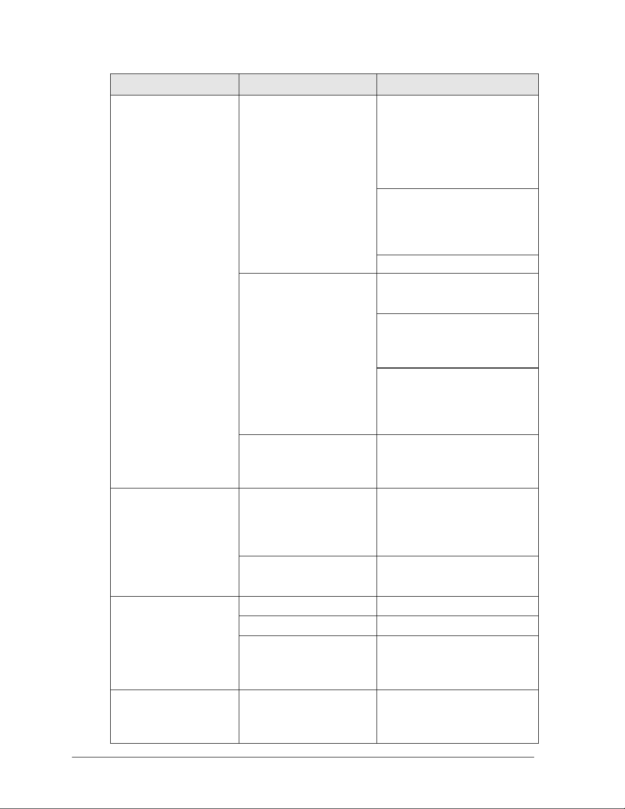
Problem
Possible Cause
Solution/Items to Check
Check that the green POWER and
amber RADIO IN RANGE indicators
on the radio receiver in the
scoreboard light up when the control
console is powered on (see Section
5.9). Keep the console between 20
to 1500 feet from the scoreboard.
Move the console 20-30 feet from
the scoreboard and test again.
Verify that both the console and
scoreboard antennae are securely
tightened and in a vertical position.
Replace the radio receiver.
No signal to driver
Check that the scoreboard is
receiving the correct 120 (or 240) V
AC power (see Section 2).
Check that the red DS2 LED on the
driver lights up when sending
commands from the control console
(see Section 5.7).
Swap the driver with one known to
work correctly and with the same
part number to verify the problem.
Replace if necessary (see Section
5.7).
No power to driver
Check that the green DS1 LED on
the driver is always lit up when the
scoreboard is powered on
(see Section 5.7).
Scoreboard digits light, but
not in the correct order
Incorrect sport code
Ensure the correct sport code is
being used for the scoreboard
model. Refer to the operation
manual for the console being used
(see Section 1.4).
Incorrect driver address
Check that the scoreboard driver(s)
are set to the correct address(es)
(see Section 5.7)
Scoreboard digits light,
console works, but no
display on scoreboard
No wired signal from console
(See solution on previous page)
No radio signal from console
(See solution on previous page)
Bad/damaged field wiring
Check that the red DS2 LED on the
driver lights up when sending
commands from the control console
(see Section 5.7)
Scoreboard works, but some
LEDs always stay on
Short in digit, segment, or
indicator circuit
Swap the digit/segment/indicator
with one known to work correctly to
verify the problem. Replace if
necessary (see Sections 5.4-5.6).
24 Scoreboard Troubleshooting
 Loading...