

Page 1

All Sport® 5100 Timer
Operations Manual
ED-12501 Rev 8 – 02 December 2003
Page 2

Page 3

ED-12501
P-1196
Rev 8 – 02 December 2003
Please fill in the information below for your display; use it for reference
when calling Daktronics for assistance.
Display Serial No. ______________________________________
Display Model No. ______________________________________
Date Installed __________________________________________
DAKTRONICS, INC.
Copyright © 2003
All rights reserved. While every precaution has been taken in the preparation of this manual,
the publisher assumes no responsibility for errors or omissions. No part of this book covered by
the copyrights hereon may be reproduced or copied in any form or by any means – graphic,
electronic, or mechanical, including photocopying, taping, or information storage and retrieval
systems – without written permission of the publisher.
®
All Sport
a registered trademark of its owner.
, Chrondek®, CompuLinkTM, PanaView®, Venus® are trademarks of Daktronics, Inc. Windows® is
Page 4

Reproduction Reference
ED-12501 – P1196
All Sport 5100 Auto Racing
1. This page is for reproduction reference only and will not be included in the
manual.
2. This manual is to be copied on FRONT AND BACK PAGES -8 ½ x 11 paper.
Note: The cover page is blank on back. Section heading pages always start on a
new page; never on the back of another page.
3. The following drawings are to be inserted in alphanumeric order in Appendix A:
Reference Drawings.
Print both A and B Drawings full size; print A drawings back-to-back.
A Drawings
A-115078 A-143770
A-124632 A-164750
A-124690 A-180514
A-125290 A-180521
A-139243 A-180566
A-139244 A-180922
A-139347 A-180923
A-139399 A-181729
A-143444 A-195690
A-143453
B Drawings
B-123256 B-145382
B-139666 B-145433
B-144445 B-164173
4. Materials to be inserted in this manual include the following:
Note 1: Appendices B, C, D, E, F and H are permanent, and materials are in
place.
Note 2: In Appendix G: Sport Code Labels, insert All Sport 5000 Sport Code
Labels (LL-2458)
Note 3: In Appendix I: Auto Racing Sport Codes, insert Drawing A-115078:
Address Table, 1-128. Insert drawing after the first page of this appendix.
Note: This drawing is also in Appendix A.
4. Use a blue window cover and a blue back.
5. Punch all pages, window cover and back cover along the left edge and bind.
6. Please direct questions and suggestions to Engineering Support.
Page 5

Table of Contents
Section 1: All Sport 5100 Operation ..............................................................1-1
1.1 How To Use This Manual ......................................................................... 1-1
1.2 Introduction............................................................................................... 1-1
1.3 Console Overview.....................................................................................1-2
Inspect for Damage ............................................................................ 1-3
1.4 Console Connectors................................................................................... 1-3
1.5 Basic Console Operation ........................................................................... 1-3
1.6 Sport Inserts............................................................................................... 1-3
1.7 Racing Insert Operation.............................................................................1-4
1.8 Startup .......................................................................................................1-6
1.9 Setting Radio Channels ............................................................................. 1-7
Radio Channel Setting: Single Controller Systems............................1-9
Radio Channel Setting: Multiple Controller with Single
Broadcast Group........................................................................1-10
Radio Channel Setting: Multiple Controller with Multiple
Broadcast Systems.....................................................................1-11
Section 2:
2.1 Transponder Interface Overview and Operation ....................................... 2-1
2.2 Menu.......................................................................................................... 2-3
2.3 Edit Settings...............................................................................................2-5
2.4 Manual and Automatic Mode Keys........................................................... 2-9
2.5 Manual Mode Keys ................................................................................. 2-10
2.6 Default Settings.......................................................................................2-11
Transponder Interface Operation ................................................2-1
Basic Operation for Transponder Interface........................................ 2-2
New Race ........................................................................................... 2-3
New Code...........................................................................................2-4
Race/Qualify Mode ............................................................................ 2-5
Blank with 1st Position.......................................................................2-6
Show Passing Lap Time..................................................................... 2-6
Show First Pass .................................................................................. 2-7
Starting Position Displayed................................................................ 2-7
Maximum Position Displayed............................................................ 2-8
Position Display Time........................................................................ 2-8
Restart Position Display Cycle...........................................................2-8
Current Position.................................................................................. 2-9
Position -1, Position +1...................................................................... 2-9
Red, Yellow, Green Status.................................................................2-9
Black Flag ..........................................................................................2-9
Display Laps....................................................................................... 2-9
Display Time.................................................................................... 2-10
Lap.................................................................................................... 2-10
Current Lap Time............................................................................. 2-10
Car Number...................................................................................... 2-10
Lap Number......................................................................................2-11
Time ................................................................................................. 2-11
Table of Contents i
Page 6

Section 3:
3.1 Oval Track Posting Keys........................................................................... 3-1
Section 4:
4.1 Common Keys...........................................................................................4-2
4.2 Oval Track Timing Keys ...........................................................................4-2
4.3 Lane Track Timing Keys........................................................................... 4-5
4.4 Menu..........................................................................................................4-5
4.5 Photocell Timing Interface ........................................................................4-8
Oval Track Posting ....................................................................... 3-1
Lap 3-1
Red, Yellow, Green Status .................................................................3-1
Black Flag...........................................................................................3-2
Display Black Flag .............................................................................3-2
Display Laps.......................................................................................3-2
Display Time......................................................................................3-2
Count Up/Down .................................................................................3-2
Set Main Clock...................................................................................3-2
Start/Stop............................................................................................3-3
Swap Keys..........................................................................................3-3
Place Keys..........................................................................................3-3
Set Car Position..................................................................................3-3
Oval and Lane Track Photocell Timing Operation .................... 4-1
Swap Keys..........................................................................................4-2
Place Keys..........................................................................................4-2
Reset All Places..................................................................................4-2
Red, Yellow, Green Status .................................................................4-3
Black Flag...........................................................................................4-3
Display Black Flag .............................................................................4-3
Reset................................................................................................... 4-3
Display Best Lap Time.......................................................................4-3
Display Running Time........................................................................4-3
Display Time of Day..........................................................................4-3
Set Time..............................................................................................4-4
Start Enable, Lap Enable, Stop Enable...............................................4-4
Laps....................................................................................................4-4
Start .................................................................................................... 4-5
Stop.....................................................................................................4-5
Reset................................................................................................... 4-5
New Race ...........................................................................................4-5
New Code...........................................................................................4-6
Dimming Level...................................................................................4-6
Separate Photocell Lanes.................................................................... 4-7
Time of Day........................................................................................4-7
Photocell Inputs..................................................................................4-8
Switch Outputs ...................................................................................4-8
Power Connections.............................................................................4-8
Section 5:
ii Table of Contents
Lane Timing/Water Slide Timing ................................................. 5-1
5.1 Timer Information .....................................................................................5-1
Water Slide Timer Information ..........................................................5-1
Lane Timing Information...................................................................5-2
5.2 Timing Keys..............................................................................................5-2
Start Timer.......................................................................................... 5-2
Page 7

Stop timer........................................................................................... 5-2
Toggle Lane View on LCD................................................................ 5-2
Reset Timer (Lane Timing Mode)...................................................... 5-3
Reset Timer (Water Slide Mode) ....................................................... 5-3
Timer Photocell Status ....................................................................... 5-3
Set Best Time ..................................................................................... 5-4
D.Q. Lane (Lane Timing Mode Only)................................................5-4
5.3 Menu.......................................................................................................... 5-5
New Game.......................................................................................... 5-5
New Code...........................................................................................5-5
Dimming Level...................................................................................5-5
Edit Settings ....................................................................................... 5-6
5.4 Settings...................................................................................................... 5-6
Set Arming Delay...............................................................................5-7
Reset Clock Time............................................................................... 5-7
Set Hold Time .................................................................................... 5-8
Timing Mode...................................................................................... 5-8
Timer Precision .................................................................................. 5-8
Select Best Time................................................................................. 5-9
5.5 Default Settings.........................................................................................5-9
Section 6:
6.1 Track Keys ................................................................................................6-2
6.2 Menu.......................................................................................................... 6-4
6.3 Settings...................................................................................................... 6-8
Track Timing..................................................................................6-1
Reset................................................................................................... 6-2
Lane Mode..........................................................................................6-2
Place Mode.........................................................................................6-3
Non–Lane Mode................................................................................. 6-3
Home and Guest 1, 2 and 3 Score...................................................... 6-3
Event and Heat................................................................................... 6-4
Lane ON/OFF..................................................................................... 6-4
Lane Status......................................................................................... 6-4
Lane Place Order................................................................................6-4
Edit 6-4
New Game.......................................................................................... 6-5
New Code...........................................................................................6-5
Dim 6-5
Home Roster, Guest Roster................................................................ 6-6
Display Menu.....................................................................................6-6
Edit Settings ....................................................................................... 6-7
Time of Day........................................................................................6-7
Guest 2 and Guest 3 ...........................................................................6-8
Lanes Used......................................................................................... 6-9
Timer Precision .................................................................................. 6-9
Cycle Hold Time................................................................................6-9
Default Settings.................................................................................. 6-9
Section 7:
Table of Contents iii
Drag Racing Interface ...................................................................7-1
7.1 CompuLink™ Interface............................................................................. 7-2
7.2 Chrondek C-33 Portatree Interface............................................................7-2
7.3 Test Mode..................................................................................................7-3
7.4 Keys and LCD Function............................................................................ 7-4
Score Test Keys.................................................................................. 7-4
Page 8

Loopback Test Keys...........................................................................7-4
Data Posting Keys ..............................................................................7-4
7.5 Menu..........................................................................................................7-5
New Game..........................................................................................7-5
New Code...........................................................................................7-5
Dimming Level...................................................................................7-6
Cycle Time .........................................................................................7-6
Monitor Port.......................................................................................7-7
Section 8:
Appendix A: Reference Drawings .....................................................................A-1
Appendix B: Transponder Reference Materials...............................................B-1
Appendix C: All Sport 5100................................................................................C-1
Appendix D: All Sport 5100 Racing RTD Items................................................D-1
Appendix E: Daktronics Racing Display Protocol...........................................E-1
Appendix F: Rmonitor-Supported Protocol Packets ..................................... F-1
Getting Started/Troubleshooting – AMB Timing
Software Interface......................................................................... 8-1
8.1 Getting Started...........................................................................................8-1
8.2 Transponder Software Information............................................................8-1
RentiX Settings...................................................................................8-1
ChronX Settings .................................................................................8-2
8.3 Troubleshooting......................................................................................... 8-2
Appendix G: Sport Code Labels........................................................................G-1
Appendix H: All Sport 5100 Quick Start Reference.........................................H-1
Appendix I: Auto Racing Sport Codes ............................................................. I-1
iv Table of Contents
Page 9
Section 1: All Sport 5100 Operation
This manual explains the setup and operation of the All Sport® 5100 Auto Racing
Control Console. For questions regarding the safety, installation, operation or
service of this system, please refer to the telephone numbers listed on the cover page
of this manual.
1.1 How To Use This Manual
Daktronics identifies manuals by their engineering document number, or ED
number, which is located on the cover page. Any supplemental manuals referenced
in this manual will be identified by their ED numbers. This manual, for example,
would be referred to as ED-12501.
Daktronics sales literature is identified by an SL number in one of the lower corners
of each page. Typically, the SL prefix, a zero and the last four digits of the number
are used for identification, as in SL02345.
The box at right illustrates the Daktronics drawing numbering system. The drawing
number is located
in the lower-right
corner of the drawing
label (in the example,
7087-P08A-69945).
Drawings in this
manual are referenced
by their last set of
digits and the letter
preceding them. In
Figure 1, the drawing
would be referred to as Drawing A-69945. Drawings are grouped and inserted in
alphanumerical order in Appendix A.
Figure 1: Daktronics Drawing Label
1.2 Introduction
This section explains the operation of the All Sport 5100 Auto Racing Control
Console, which is part of the Daktronics All Sport 5000 Series family of display
controllers.
Important Safeguards
1. Read and understand these instructions before installing your console.
2. Do not drop the control console or allow it to get wet.
3. Do not let power cords touch hot surfaces or hang over the edge of a table
or other surface where they might be damaged or cut.
4. If an extension cord is necessary, use a three-prong, polarized cord.
Arrange the cord with care so that event personnel or spectators cannot trip
over it or pull it out.
All Sport 5100 Operation 1-1
Page 10
5.
Always turn off and/or unplug the control equipment when it is not in use.
Never yank a power cord to pull a plug from an outlet. To disconnect, grasp
the plug firmly and pull.
6. To avoid electrical shock, do not disassemble the control equipment.
Incorrect reassembly can cause electric shock to the operator, faulty
operation, or permanent damage to the controller and display circuits.
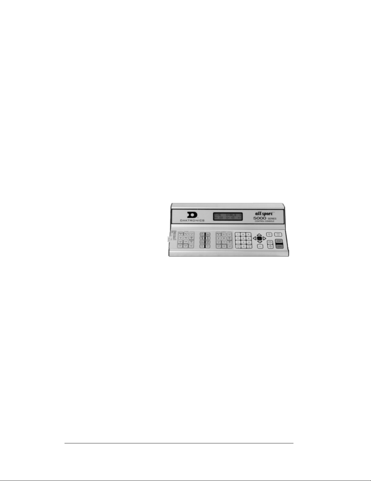
1.3 Console Overview
The All Sport 5100 Auto Racing Controller is a state-of-the-art scoring and timing
system.
The anodized aluminum console features a sealed, "snap-action" keyboard with
changeable keyboard inserts to input race information and/or control the
scoreboards. A 32-character, two-line liquid crystal display (LCD) prompts the user
through the operation of the controller and provides vital feedback of race data.
The console operates on 120 V AC power (60 Hz, 6 watts maximum), and an
internal battery backup assures that the event will be timed even if there is a power
failure in the arena. (The console's auto-memory feature stores current event
information in case of power
failure, even without a
battery.)
The LCD screen of the 5100
is backlit to provide optimum
viewing of current event
information, even in low-light
areas, and an audible beep
sounds to indicate when a
command has been received.
Operation of the All Sport 5100 is simple. The user enters a four-digit code on
power-up to indicate the operating mode for the race. Basic choices include Manual
mode, which uses infrared photocells for timing, or Automatic mode, with AMB
transponders for timing. The type of information that can be displayed is determined
by the capabilities of the scoreboard. The All Sport can be used with numeric (digitonly) scoreboards, full matrix displays with alphanumeric character capabilities, or a
combination of both.
The controller features timing settings from 1/10th to 1/100th of a second, and
photocell timing permits selectable timing to 1/1000th of a second.
The console case is approximately 16.25" (413mm) long by 9" deep (229mm). Its
maximum top height is 4.25" (114mm). The controller weighs 7.5 pounds.
As a safety feature, this product has a three-wire, ground-type plug equipped with a
third (grounding) pin. This plug only fits into a grounding-type power outlet. (If you
are unable to insert the plug into the outlet, contact a qualified electrician to replace
the obsolete outlet.) Refer to the table on the following page for specific model
descriptions.
Figure 2: All Sport 5000 Series Console
1-2 All Sport 5100 Operation
Page 11

Model Description
5100 120 volt, standard programming
5120 230 volt, standard programming
Console event data may be transmitted through standard wire signal cabling or fiberoptic cable. A radio-control wireless model is also available.
The All Sport 5100 is ETL-listed to UL standards and is CSA-tested.
Inspect for Damage
When you first open your console packages, inspect for shipping damage such as
dents or rattles. Verify that all equipment is included as itemized on the packing slip.
Immediately report any deficiencies to Daktronics. Save all packing materials for
shipping in case warranty repair or exchange becomes necessary.
1.4 Console Connectors
Reference Drawing:
Rear View, A/S 5100 Connector Assignments............Drawing A-124632
Refer to Drawing A-124632 in Appendix A.
1.5 Basic Console Operation
The console face consists of a two-line by 16-character LCD screen, sport-specific
keyboard insert, numeric keypad, operation keys, main clock keys, and LEDs for
status.
Throughout this manual the names or letters of keys on the keyboard are enclosed in
angle brackets such as <
insert are explained in detail in the section of the manual devoted to that specific
application.
In addition, Quick Start References for keyboard operation are provided in
Appendix H.
ENTER>. All of the keys pertaining to a specific sport code
1.6 Sport Inserts
Sport inserts, sometimes called keypad inserts, are used to allow a single console to
control multiple sports or different applications of the same sport. Select the proper
insert from the chart in Section 1.7, and slide it into the insert opening on the left
side of the console until it stops. To remove a sport insert, pull on the tab that
extends from the left side of the console. The insert will slide out easily.
If an insert is lost or damaged, a copy of the insert drawing in Appendix A can be
used until a replacement can be ordered.
All Sport 5100 Operation 1-3
Page 12

Use the labels provided in Appendix G to attach the correct code number to each
sport insert. Write the code number in the space provided in each section of this
manual.
If you do not know the code number for your scoreboard, refer to Appendix I. If
you do not know the model number of your scoreboard, refer to the installation and
maintenance manual provided with the display.
1.7 Racing Insert Operation
A keypad insert identifies the action keys required in the normal course of a race or
other sporting event. Each insert has a corresponding list of code numbers and
display models. The code numbers configure the console to control the display
specified by the model number. For example, Code 301 enables the console to
control a CH-2001 display.
Code numbers also configure the console for a specific sport mode as shown on the
sport insert. This enables the console to control the display as specified by the keys
on the insert. The following table lists the codes available:
Code
Mode of
Operation
Displays Insert
Photocell
300
301
303
310
311
320
333
336
401 Manual posting
433 Manual posting
All Sport 5100
Console Only
Transponder
interface
Photocell
All Sport 5100
Console Only
Photocell
All Sport 5100
Console Only
Photocell
All Sport 5100
Console Only
Photocell All Sport
5100 Console
Only
Transponder
interface
Transponder
interface
(Continued on following page)
Oval track photocell code
(CHTS-300 replacement)
CH-2001, CH-2002, CH-700,
positions 1-12
Lane track photocell code
CHTS-300 replacement
Multiple-lane track timing code
lane order
Multiple-lane track timing code
place order
Water slide timing 0G-143770
CH-14XX, CH-10XX, CH-8XX,
CH- 16XX, pylon positions 1-45
for AR-XX scoreboards
Alphanumeric car number RTD
w/fixed-digit time (no fixed-digit
car numbers)
CH-2001, CH-2002, CH-7001,
positions 1-12
CH-14XX, CH-10XX, CH-8XX,
CH- 16XX, pylon positions 1-45
for AR-XX scoreboards
0G-139347
0G-139243
0G-139399
0G-143770
0G-143770
0G-139243
0G-139243
0G-139243
0G-139243
1-4 All Sport 5100 Operation
Page 13
(Continued from previous page)
Code
555
556
995 Manual posting
Mode of
Operation
Compulink
Startrak
Chrondek C38/
Portatree
Displays Insert
Compulink timer/display
configuration
Chrondek C38/Portatree
timer/display configuration
CH-14XX, CH-10XX, CH-8XX,
CH- 16XX, pylon positions 1-45
for AR-XX scoreboards
0G-164750
0G-164750
0G-139244
In most cases, pressing a key immediately changes the display. Some control actions
require pressing additional keys. Keys that require additional information are marked
with a dot, "•". The additional information required is usually a number followed by
ENTER> key.
the <
Some keys contain a +1 symbol. Pressing one of these keys once increments
(increases) the value of the corresponding field by one. A key with a –1 symbol
decrements (decreases) by one.
Certain keys have been grouped together under the heading "Manual." These keys,
in addition to the keys used in transponder mode, are used only when operating in
Manual mode.
Other keys on the console include:
<
CLEAR>Clears the LCD of numeric information. Serves as <NO> for
input prompts.
ENTER*>Completes an action. The asterisk is a reminder that this key
<
must be pressed when an asterisk appears on the LCD.
Serves as <
<
MENU> Invokes sport-specific menu options.
YES> for input prompts.
All Sport 5100 Operation 1-5
Page 14
1.8 Startup
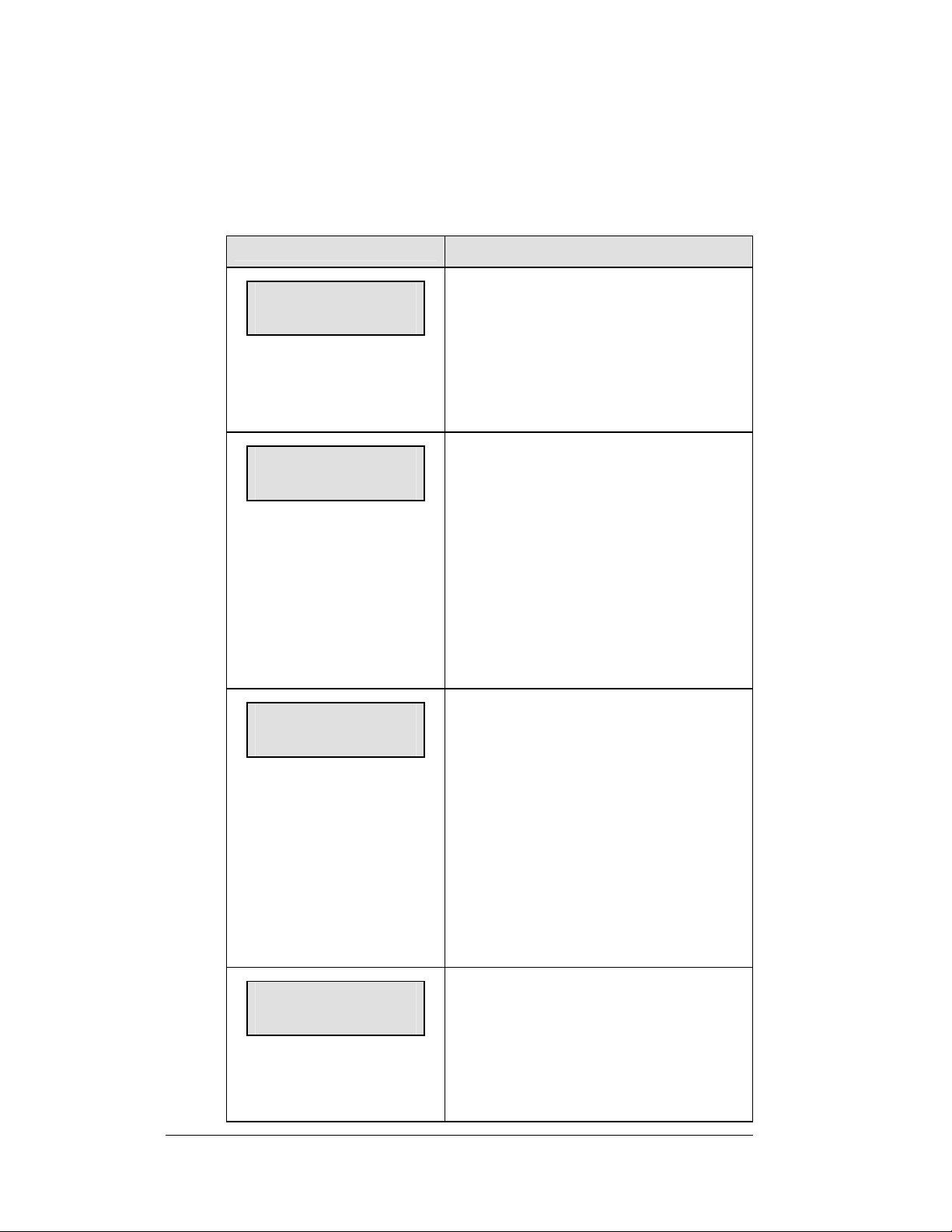
When the LCD screen message appears as shown, the following actions may be
selected:
LCD Display
AS-5100 v1.4.1
ED-11544
PREV CODE nnnn
RESUME GAME?
nnnn
= last code selected
SELECT CODE
CODE nnnn
nnnn = last code selected
Radio chan nn
Enter or change
nn = last radio channel used
Action
The console performs a self-test when it is
powered on. During the self-test, a message
displays the version of the standard software
loaded in the console.
V = version number and revision number
O = standard software number
When the self-test completes, a prompt
displays the code number for the last event
run. This is useful when power to the console
is lost during an event.
Press <YES> to resume the last event stored
in memory. The console is now ready for
operation.
Press <NO> to start a new event or change to
a different sport. The console will prompt for
a new code number as shown below.
The Select Code prompt allows you to accept
the last code selected (displayed on the second
line) or enter a new code.
To accept the code shown, press <ENTER>.
To select a new sport code:
1. Get the code number from the sport
insert or the section of the manual for
that event.
2. Use the number keys to enter the new
four-digit code. Press <ENTER>.
If a new code is selected and the radio option
is installed, the console prompts for a channel.
When Resume Game is used, the last channel
selected is used.
ENTER> to accept the channel number
Press <
or enter a new channel number.
1-6 All Sport 5100 Operation
Page 15

1.9 Setting Radio Channels
Reference Drawings:
Installation: Outdoor,
Gen IV Radio Receiver..........................................Drawing A-180514
Installation: Indoor,
Gen IV Radio Receiver..........................................Drawing A-180521
Channel Selection;
Single Control Console, Gen IV ............................Drawing A-180566
Channel Selection;
Single Broadcast Group, Gen IV...........................Drawing A-180922
Channel Selection;
Multiple Broadcast Group, Gen IV.........................Drawing A-180923
Indoor LED Driver Update
For Gen IV Radio Receiver...................................Drawing A-181729
Refer to Appendix A for the Reference Drawings listed here.
The radio receiver units used in the scoreboards have a channel setting switch that
can be set from 1 to 8 (channels 0, and 9-15 are not used.) A radio receiver will
accept data from a console transmitter with the same channel (and broadcast group)
setting.
The receivers also have a jumper that can be used to select broadcast group 1 or
broadcast group 2. A “Broadcast Group” defines a group of radio receivers that in
addition to “listening” to the channel selected on the channel switch will also
“listen” for data broadcast on their broadcast channel. There are a total of two
broadcast groups available.
Each radio receiver will accept data sent from the broadcast channel of its respective
broadcast group. This is selected by setting the transmitter (console) radio to
channel 0. Every radio receiver will also accept data sent from the “Master
Broadcast” channel. This is selected when a transmitter (console) radio is set to
Broadcast Group 0 (BCAST 0) and Channel 0.
The channel number and broadcast group set on the radio installed in each
scoreboard can be verified by cycling power to the scoreboard. Approximately
seven seconds after power up, the scoreboard will show the current channel in the
scoreboard clock digits. A CXX will first be shown where XX is the current radio
channel number. This will be followed by BXCY where X is the current broadcast
group and Y is the current channel number within this broadcast group.
There are three different radio scenarios that can be accommodated.
1. Single Controller System:
In a Single Controller system, all radio receivers and all scoreboards receive
signal from the same All Sport console at all times. The default channel
and broadcast group settings on the receiver are not typically modified. An
example of this type of system is a typical high school football installation.
2. Multiple Controller System With a Single Broadcast Group:
In a Multiple Controller system with a single broadcast group, there are
additional All Sport Controllers for controlling multiple scoreboards.
All Sport 5100 Operation 1-7
Page 16
There is never a scenario where groups of scoreboards that were run by
individual controllers need to be run by a single controller. An example of
this type of system is a softball complex with multiple fields and a
scoreboard on each field.
3. Multiple Controller with Multiple Broadcast Groups:
In a Multiple Controller with Multiple Broadcast (Split Court Operation)
system, there are additional All Sport Controllers that can control multiple
scoreboards. The broadcast group jumper is used to select broadcast group
1 or 2. By changing All Sport settings to a Broadcast address, a single All
Sport Controller can control all scoreboards or specific groups of
scoreboards (defined by the broadcast group.) One example of this scenario
is split court operation in Basketball installations, where scoreboards are
used to score multiple games at once, but can be grouped together to show
one game if necessary. Refer to drawings listed on the previous page for
more information.
The All Sport Console will automatically detect when a radio transmitter is installed
and will prompt the user for transmitter settings.
The All Sport Console will show the current transmitter radio status on the LCD
when a code is entered. An overview of radio settings is shown below.
LCD Display
RADIO SETTINGS
BCAST Y CHAN XX
The LCD will toggle
these screens
* = current edit item
Enter to accept
clear to modify
The bottom line shows the
current setting
bcast group 1
radio chan 01
The default setting is
Broadcast 1 Channel 1
The LCD shows the current radio settings along
with a prompt to accept or modify these values.
If the radio settings are correct, press <ENTER>.
If these values are incorrect, press <CLEAR>
If <CLEAR> is pressed to modify the radio
settings, the LCD at the left is shown, allowing
edit of the Channel or Broadcast group setting.
Edit the Broadcast Setting. Use the number keys
to enter the desired broadcast group and press
<ENTER> to accept.
Broadcast Group Setting
0- Master Broadcast – All Receivers
1- Broadcast Group 1
2- Broadcast Group 2
The asterisk will move to the channel setting. Use
the number keys to edit this value and press
<ENTER> to accept. Edit the channel number to
the desired value and press <ENTER> to accept.
(Continued on following page)
Action
1-8 All Sport 5100 Operation
Page 17
LCD Display
(Continued from previous page)
Action
Channel Setting
0- Broadcast Channel for this Broadcast Group
BCAST = 0 – Master Broadcast (all radios)
BCAST = 1 – Broadcast Group 1
BCAST = 2 – Broadcast Group 2
1-4 Channels that may be used within Broadcast
groups 1 or 2 (BCAST = 1 or BCAST = 2.)
5-8 Channels that may be used within Broadcast
group 1 only (BCAST = 1.)
Radio Channel Setting: Single Controller Systems
Typically all Single Controller systems will use the default setting BCAST = 1,
CHAN = 1. All radio receivers must be set with a switch setting of 1 with the
Broadcast 1 (BCAST 1) jumper set.
If you suspect interference from a nearby Daktronics system, press <CLEAR> at the
“RADIO SETTINGS” prompt to change the channel number.
Typically all Multiple Controller systems will use channel 1 for the first controller.
All other controllers will use sequential channel settings (2-8)
LCD Display
RADIO SETTINGS
BCAST Y CHAN XX
The LCD will toggle
these screens
Enter to accept
clear to modify
bcast group 1
radio chan 01
The bottom line shows
default settings.
The LCD shows the current radio settings along
with a prompt to accept or modify these values.
If the radio settings are correct, press <ENTER>.
If these values are incorrect, press <CLEAR>
If <CLEAR> is pressed to modify the radio
settings, the LCD at the left is shown, allowing
edit of the Channel or Broadcast group setting.
Edit the Broadcast Setting. Use the number keys
to enter the desired broadcast group and press
<ENTER> to accept.
(Continued on following page)
Action
All Sport 5100 Operation 1-9
Page 18

(Continue from previous page)
LCD Display
Broadcast Group Setting
1- Use this setting for all single controller
systems.
The asterisk will move to the channel
setting. Use the number keys to edit this
value and press <ENTER> to accept. Edit
the channel number to the desired value
and press <ENTER> to accept.
Channel Setting
1-8 Channels that may be used with broadcast
channel 1. The channel switch on the
receiver must match this value and the
Broadcast 2 (BCAST2) jumper must be
removed.
Action
Radio Channel Setting: Multiple Controller with Single
Broadcast Group
Typically all multi-controller systems will use Broadcast 1 and Channel 1 for the
first controller and Channels 2-8 for all remaining controllers. All radio receivers
must be set with a switch setting corresponding to the console controlling the
scoreboard and a Broadcast 1 (BCAST 1) jumper set.
If you suspect interference from a nearby Daktronics system, press <CLEAR> at the
“RADIO SETTINGS” prompt to change the channel number.
Typically all Multiple Controller systems will use channel 1 for the first controller.
All other controllers will use sequential channel settings (2-8)
1-10 All Sport 5100 Operation
Page 19
LCD Display
RADIO SETTINGS
BCAST Y CHAN XX
The LCD will toggle
these screens
Enter to accept
clear to modify
* = current edit item
bcast group 1
radio chan 01
The bottom line shows
default settings.
Action
The LCD shows the current radio settings along
with a prompt to accept or modify these values.
If the radio settings are correct, press <ENTER>
If these values are incorrect, press <CLEAR>
If <CLEAR> is pressed to modify the radio
settings, the LCD at the left is shown, allowing
edit of the Channel or Broadcast group setting.
Edit the Broadcast Setting. Use the number keys
to enter the desired broadcast group and press
<ENTER> to accept.
Broadcast Group Setting
1- Use this setting for all multiple controller
with single broadcast group setups.
The asterisk will move to the channel
setting. Use the number keys to edit this
value and press <ENTER> to accept.
Edit the channel number to the desired
value and press <ENTER> to accept.
Channel Setting
1-8 Channels that may be used with broadcast
channel 1. The channel switch on the
receiver must match this value and the
Broadcast 2 (BCAST2) jumper must be
removed.
Radio Channel Setting: Multiple Controller with Multiple
Broadcast Systems
Typically all multiple controller systems will use Broadcast Group 1 Channel 1 for
the first controller in Broadcast Group 1 and Broadcast Group 2 Channel 1 for the
first controller in Broadcast Group 2. All other consoles in each group are added
sequentially, using channels 2-4.
All Sport 5100 Operation 1-11
Page 20
LCD Display
RADIO SETTINGS
BCAST Y CHAN XX
The LCD will toggle
these screens
Enter to accept
clear to modify
bcast group 1
radio chan 01
* = current edit item
The bottom line shows
default settings.
Action
The LCD shows the current radio settings along
with a prompt to accept or modify these values.
If the radio settings are correct, press <ENTER>
If these values are incorrect, press <CLEAR>
If <CLEAR> is pressed to modify the radio
settings, the LCD at the left is shown, allowing
edit of the Channel or Broadcast group setting.
Edit the Broadcast Setting. Use the number keys
to enter the desired broadcast group and press
<ENTER> to accept.
Broadcast Group Setting
0- Master Group – All receivers
1- Broadcast Group 1
2- Broadcast Group 2
The asterisk will move to the channel setting. Use
the number keys to edit this value and press
<ENTER> to accept. Edit the channel number to
the desired value and press <ENTER> to accept.
Channel Setting
0- Broadcast Channel for this Broadcast
Group.
BCAST = 0 – Master Broadcast (all
radios)
BCAST = 1 – Broadcast Group 1
BCAST = 2 – Broadcast Group 2
1-5 Individual Channel within
Broadcast Group 1 or 2
.
1-12 All Sport 5100 Operation
Page 21
Section 2: Transponder Interface
Operation
Sport Insert 0G-139243
Reference Drawing:
Insert, Transponder Interface Code..........................................Drawing A-139243
The sport insert drawing is located in Appendix A. The Quick Start Reference is located in
Appendix H.
Refer to the information in Sections 1.5 – 1.8 to start the console and to use the sport insert.
Read the material carefully to fully understand the following operating instructions.
If an insert is lost or
damaged, a copy of
the insert drawing in
Appendix A can be
used until a replacement
is ordered.
Use the labels provided
in Appendix G to attach
the correct code number
label at the appropriate
location on the sport insert.
Write the code number in
the boxes below:
Figure 3: 0G-139243
Sport Insert Code (Code 300 is for All Sport 5100 consoles only)
If you do not know the code number for your scoreboard, refer to Appendix I in this manual.
If you do not know the model number of your scoreboard, refer to the installation and
maintenance manual provided with the scoreboard.
2.1 Transponder Interface Overview and Operation
Reference Drawings:
Oval Track Timing System Layout...............................Drawing B-139666
Insert, A/S 5000, Transponder Interface Code.............Drawing A-139243
Daktronics scoreboards and controllers interface to a combination of AMB Rmonitor
and Daktronics results protocol. This protocol is available with a number of AMB
results software products, the most common being RentiX and ChronX. RTS, RTSX
and SimpliX currently do not offer a Daktronics scoreboard output and can only be
used with the Daktronics AMB Interface for Windows
Interface for Windows must also be used if a version of ChronX earlier than 2.0 is
in place.
Transponder Interface Operation 2-1
®
software. Daktronics AMB
Page 22

Daktronics systems can include matrix displays controlled by a Venus
®
display
controller, numeric or scoreboard-type displays, or a combination of both. The
interface between AMB results software and Daktronics products depends on the
type of display being used as well as the AMB software. Refer to the following chart
to locate the desired interface application.
Display
Matrix
Matrix
Matrix and
numeric
(fixed digit)
Numeric
(fixed digit)
Type
Daktronics
Controller(s)
Venus series RTS
Venus Series
and All Sport
5100
All Sport
5100
AMB Software Windows
Interface
Required?
Yes
RTSX
ChronX
(any version)
SimpliX
RentiX
ChronX
(V 2.0 or later)
RentiX,
ChronX
(V2.0 or later)
Refer to
ED11053
No SL03541
No SL03639
Sales
Literature
Reference
SL03641
SL04213
SL03640
SL04016
The following materials illustrate the hardware and software required for the
different display applications. These sales reference materials are grouped and
inserted in numerical order in Appendix B.
SL03639 – Transponder Feed to Daktronics Pylon
SL03640 – Transponder Feed to Daktronics LED Scoreboard
SL03641 – Transponder Feed to Daktronics Matrix Scoreboard
SL04016 – Transponder Feed to Daktronics Incandescent Fixed Digit
Scoreboard
SL04213 – Transponder Feed to Daktronics Matrix and Fixed Digit Time
Scoreboard
Refer to Drawing B-139666 in Appendix A for information on connections to the
junction boxes, controllers and computers.
K Note: Third-party companies wishing to interface their software packages to
Daktronics numeric scoreboards should refer to Appendix E: Daktronics Racing
Display Protocol. This appendix lists the protocol required to feed results data
through a Daktronics All Sport controller for presentation on a Daktronics numeric
display. For information on interfacing to a Daktronics Venus controller, contact
Daktronics, Inc.
Basic Operation for Transponder Interface
In most cases, the top line of the control console's LCD shows position, car number
and lane number. The bottom line of the liquid crystal display shows the current lap
and the letter "R" or "Q" to indicate if the console is in Race mode or Qualify mode.
2-2 Transponder Interface Operation
Page 23
A "QP" indicates that the console is in qualifying mode and set to show passing. The
illustration below shows car number 15 in the third position, lane 12 on lap 13 in the
race mode.
P- 3 # 15 L 12
CUR LAP 13 R
K Note: Make sure the console is in the correct mode, Qualify or Race. The
console mode should match the mode of the timing system. In Qualify mode, the
cars are displayed in order of lap times. In Race mode, the cars are displayed in
order of race position.
2.2 Menu
The <MENU> key selects from a list of options specific to the racing sport. The up
and down arrow keys <
Pressing any key other than the <
function.
K Note: Not all prompts must be answered. The following menu functions may be
available:
>, <> allow the user to scroll through the menu list.
YES>, <NO> or arrow keys will exit the menu
New Race
When the LCD screen message appears as shown, the following actions may be
selected:
LCD Display
MENU-MAIN
NEW RACE?
YES> to clear all of the program data
Press <
for the last race or the race in progress and
begin running a new race.
NO> to resume the event in progress
Press <
using the current data and to exit the menu.
Press the down arrow key <
next selection.
Action
> to scroll to the
Transponder Interface Operation 2-3
Page 24
New Code
When the LCD screen message appears as shown, the following actions may be
selected:
LCD Display
MENU-MAIN
NEW CODE?
MENU- Dimming
level (0-9): nn%
nn = current level
None = bright <0>
90% = <1>
80% = <2>
70% = <3>
60% = <4>
50% = <5>
40% = <6>
30% = <7>
20% = <8>
10% = <9>
Action
YES> to begin selection of a new code
Press <
from the Enter Code prompt.
NO> to resume the race in progress
Press <
using the current data and to exit the menu.
Press the down arrow key <
next selection
Press <0> through <9>, or use the left or right
arrow keys <
for the digits on the scoreboard.
Press <NO> to resume the game in progress
using the current data, and exit the Menu.
Press the down arrow key <
next selection.
Note:
> <>, to select the intensity
Dim levels pertain to outdoor LED
products. Incandescent and indoor
LED products only support one level
of dimming at 50%.
> to scroll to the
> to scroll to the
2-4 Transponder Interface Operation
Page 25
Race/Qualify Mode
LCD Display
CURRENT MODE?
*RACE←→QUALIFY
* = current setting
Action
Press the left or right arrow keys <
to select Race or Qualify mode.
>, <>
The Race/ Qualify setting selects the order of
positions displayed. In Race mode, the
competitors are listed in order of current race
position. In Qualify mode, competitors are
listed in order of fastest lap time. Make sure
the console setting matches the current race
status of the controlling software
K Note: The Race/Qualify status is shown
on the bottom line of the LCD as an "R" or
"Q."
2.3 Edit Settings
LCD Display
MENU- MAIN
EDIT SETTINGS?
Action
YES> or the right or left arrow key
Press <
<
>, <> to select the Settings submenu
and show the first prompt on the LCD.
NO> to resume the event in progress
Press <
using the current data and to exit the menu.
Press the down arrow key <
next selection.
> to scroll to the
K Note: All settings pertain to the operation
of the console in transponder interface codes.
The Settings menu may be neglected if
transponders are not used.
Transponder Interface Operation 2-5
Page 26
Blank with 1st Position
LCD Display
BLANK ALL WHEN
1ST POS RCVD? N*
* = current setting (Y/N)
Action
YES> yes to blank all positions (other
Press <
than first place) when a first-place time is
received from the transponder.
All other positions will be displayed as they
cross the loop.
K Note: This setting is NOT applicable if
the console is in Qualify mode AND set to
show passing information.
Show Passing Lap Time
LCD Display
SHOW PASSING LAP
TIME INFO? N*
* = current setting (Y/N)
Action
YES> to show lap time information on
Press <
the lap time section of the scoreboard when
passing information is received from the
transponder.
K Note: Passing information will only be
displayed if the console is in Qualify mode.
This information will be displayed in the
"Current Competitor" RTD item numbers and
on fixed-digit, or numeric, time displays. For
a more detailed explanation, refer to the All
Sport 5100 Enhanced RTD item numbers in
Appendix D.
2-6 Transponder Interface Operation
Page 27
Show First Pass
LCD Display
SHOW FIRST
PASS? Y*
* = current setting (Y/N)
Action
Press <YES> to show passing information
with the first pass. Press <NO> to update the
new passing competitor with the second pass.
This setting can be used to configure the
passing display to match the qualifying track
setup. If the loop is located in such a way that
a second car crosses it while the first car is
finishing a qualifying lap, set the console to
disregard the first pass by selecting "NO."
Otherwise, if you want the display to update
on the first pass of a competitor, select "YES."
K Note: Passing information will only be
displayed if the console is in Qualify mode.
Starting Position Displayed
LCD Display
START POSITION
DISPLAYED nn
nn = current setting (Y/N)
Action
This setting selects the starting position to be
displayed in the variable-position car number
location on a numeric or fixed-digit
scoreboard.
Enter a number between 1 and 45 and press
<ENTER> to accept.
K Note: Disregard this setting if your
installation does not include a display
showing variable-position car numbers.
Transponder Interface Operation 2-7
Page 28

Maximum Position Displayed
LCD Display
MAX POSITION
DISPLAYED nn
This setting selects the maximum position to
be displayed in the variable-position car
number location on a numeric or fixed-digit
scoreboard.
nn = current setting (Y/N)
Enter a number between 1 and 45 and press
<ENTER> to accept.
K Note: Disregard this setting if your
installation does not include a display
showing variable position car numbers.
Action
Position Display Time
LCD Display
POSITION DISPLAY
TIME nn
nn = current setting (Y/N)
Enter the time (in seconds) for each position
group to be displayed on the numeric or fixeddigit scoreboard before moving to the next
group.
K Note: Disregard this setting if your
installation does not include a display
showing variable-position car numbers.
Action
Restart Position Display Cycle
LCD Display
Restart cycle
At start pos? N*
N*= current setting (Y/N)
<YES> to restart the position/car number
Press
cycle when the controller receives the position
configured as the start position.
<NO> to set the console for continuous
Press
cycle.
Action
K Note: Disregard this setting if your
installation does not include a display
showing variable-position car numbers.
2-8 Transponder Interface Operation
Page 29
2.4 Manual and Automatic Mode Keys
Current Position
LCD Display
P-nn #xxx L-yyy
CUR POS nn*
Enter the desired position number and press
<ENTER>. The car and lap number of the
driver with the selected position will be
displayed on the LCD.
nn = current position
xxx = car number
yyy = lap number
Position -1, Position +1
<POSITION -1> displays the car and lap in the next lowest position on the LCD.
POSITION +1> displays the car and lap in the next highest position on the LCD.
<
Action
Red, Yellow, Green Status
<RED> turns on the red status light on the scoreboard.
YELLOW> turns on the yellow status light on the scoreboard.
<
GREEN> turns on the green status light on the scoreboard.
<
K Note: If status is available, the controller will automatically take the status
information from the transponder interface. If this is the case, status received from
the interface will override the selected status
Black Flag
LCD Display
BLACK FLAG
nn
<BLACK FLAG •> allows the operator to
enter the number of the car that is being
black-flagged.
nn = car number to black-flag
DISPLAY BLACK FLAG > displays on the scoreboard the number of the car that
<
was black-flagged. This number will flash when displayed on the scoreboard.
.
Action
Display Laps
Displays the current lap number of the leader on the scoreboard.
Transponder Interface Operation 2-9
Page 30
Display Time
Displays the current lap time of the leader on the scoreboard.
2.5 Manual Mode Keys
The following keys are used only when a manual code is selected.
Lap
<CURRENT LAP> allows the operator to enter the value of the current lap.
LAP-1> decrements the lap number by one.
<
<
LAP +1> increments the lap number by one.
Current Lap Time
LCD Display
P-nn #xxx L-yyy
T HH:MM:SS.DCM
nn = current position
xx = car number
yy = lap number
HH:MM:SS.DCM = current lap
time
Action
Enter the value of the current lap time to be
displayed on the scoreboard.
K Note: This time will be displayed in the
current time position on the scoreboard. To
set individual lap times, use the <
key.
TIME • >
Car Number
LCD Display
P-nn #-xxx L-yyy
Enter the new car number for the selected
position and press <
Action
ENTER>.
nn CAR# xxx
nn = current position
xx = car number
yy = lap number
2-10 Transponder Interface Operation
Page 31

Lap Number
LCD Display
P-nn #-xxx L-yyy
nn LAP# yyy
nn = current position
xx = car number
yy = lap number
Time
LCD Display
P-nn #-xxx L-yyy
nn hh:mm:ss.Dcm
nn = current position
xx = car number
yy = lap number
hh:MM:SS.DCM = current lap
time
Action
Enter the new lap number for the selected
position and press <ENTER>.
Action
Enter the new lap time for the selected
position and press <ENTER>.
2.6 Default Settings
Write the settings for this installation in the spaces (Custom 1, 2 and 3) provided.
Setting Default Custom 1 Custom 2 Custom 3
Race/Qualify Mode Race
Blank on 1st
Position
Show Passing Lap
Times
Start Position for
Variable Position
Pylon
Transponder Interface Operation 2-11
No
No
16
(Continued on following page)
Page 32

Setting Default Custom 1 Custom 2 Custom 3
Max Position for
Variable Position
Pylon
Cycle Time for
Variable Position
Pylon
Restart when
Starting Position
Received
(Variable Position
Pylon)
(Continued from previous page)
45
3 seconds
No
2-12 Transponder Interface Operation
Page 33

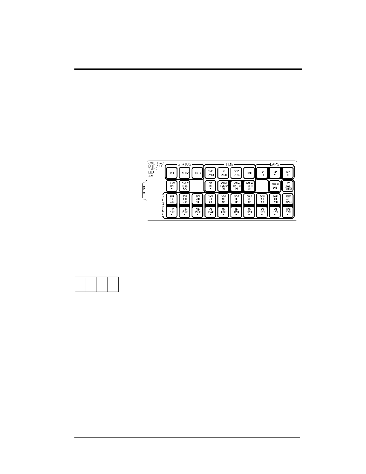
Section 3: Oval Track Posting
Sport Insert 0G-139244
Reference Drawing:
Insert, A/S 5000 Oval Track Posting...............................................Drawing A-139244
The sport insert drawing is located in Appendix A. The Quick Start Reference is located
in Appendix H.
Refer to the
information in
Sections 1.5 – 1.8 to
start the console and
to use the sport
insert. Read the
material carefully
to fully understand
the following
operating
instructions.
If an insert is lost or damaged, a copy of the insert drawing in Appendix A can be used until
a replacement can be ordered.
Use the labels provided in Appendix G to attach the correct code number label at the
appropriate location on the sport insert. Write the code number in the boxes below:
Sport Insert Code
If you do not know the code number for your scoreboard, refer to Appendix I in this manual.
If you do not know the model number of your scoreboard, refer to the installation and
maintenance manual provided with the scoreboard.
Figure 4: 0G-139244
3.1 Oval Track Posting Keys
Lap
<LAP •> edits the lap number.
<
LAP -1> decrements the lap by one.
<
LAP +1> increments the lap by one.
Red, Yellow, Green Status
<RED> turns on the red status light on the scoreboard.
YELLOW> turns on the yellow status light on the scoreboard.
<
GREEN> turns on the green status light on the scoreboard.
<
Oval Track Posting 3-1
Page 34

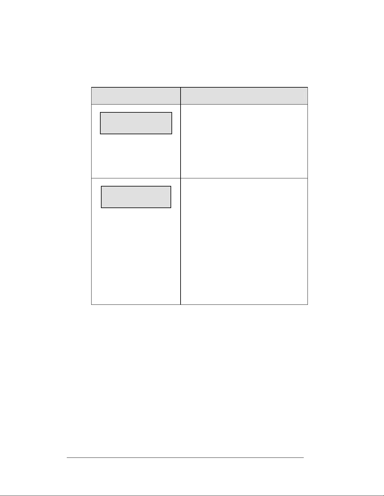
Black Flag
LCD Display
BLACK FLAG
nn = car number to black flag
Display Black Flag
<DISPLAY BLACK FLAG> shows on the scoreboard the number of the car that
was black-flagged. This number will flash when displayed on the scoreboard.
Display Laps
<DISPLAY LAPS> displays the current lap number on the scoreboard.
nn
Action
<BLACK FLAG •> allows the operator to
enter the number of the car that is being
black-flagged.
Display Time
<DISPLAT TIME> displays the time elapsed on the scoreboard.
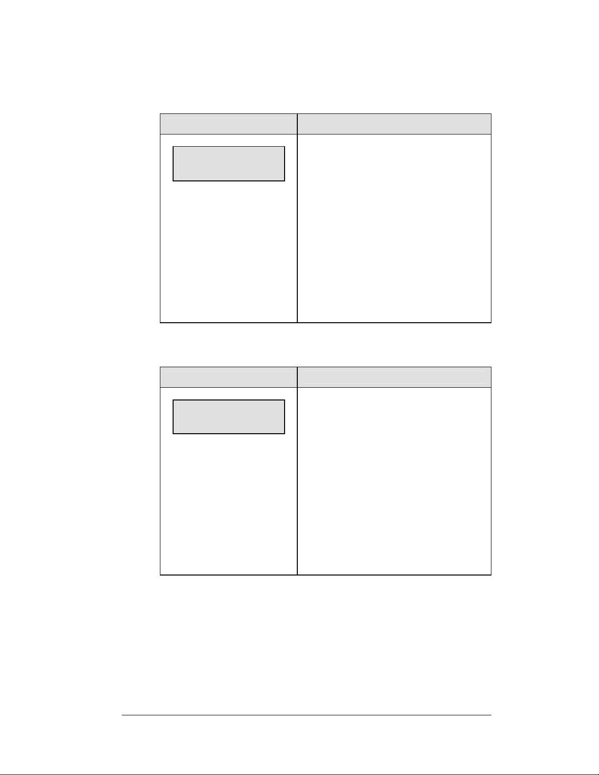
Count Up/Down
LCD Display
Main clock – up
1 – up 2 – down
Set Main Clock
LCD Display
Main clock – set
Curr 0:00
Action
<COUNT UP>sets the main clock to count
up or down. Press <
ENTER>to change count modes. The
<
controller LCD displays an up arrow <
1> or <2> and
>
if the clock is counting up, and a down
arrow <
> if the clock is counting down.
Action
SET MAIN CLOCK> sets the time on the
<
race clock.
3-2 Oval Track Posting
Page 35

Start/Stop
<START> starts the race clock.
<STOP> stops the race clock.
Swap Keys
<SWAP X Y> swaps the "X" car position with "Y" car position. This key is used
when a car overtakes another to move up in position.
Example: <
vice-versa.
SWAP 1ST 2ND> allows you to swap first place to second place and
Place Keys
Press any of the place keys to enter the car number for places 1-15.
Set Car Position
<SET CAR POSITION> can be used to quickly enter the car numbers displayed for a
series of race positions.
LCD Display
POSITION 1*
POSITION y
CAR# nn
nn = current car number for
position y
Action
Press <ENTER> to start editing car
numbers with position 1. Press the
number keys to change the starting
position to
be edited.
Enter the new car number for the
specified position and press <
ENTER>.
The LCD will display the next position
for editing. Press the up or down arrow
>, <> to move through the
keys <
positions. Press the number keys at any
time to edit the car number associated
with the displayed position.
Press <
ENTER> twice to exit the Set Car
Position function.
Oval Track Posting 3-3
Page 36

Page 37

Section 4: Oval and Lane Track Photocell
Timing Operation
Sport Insert 0G-139347 Oval Track Photocell Timing
Sport Insert 0G-139399 Lane Track Photocell Timing
Reference Drawings:
Insert; A/S 5000 Oval Track Timing ................................................Drawing A-139347
Insert; A/S 5000 Lane Track Photocell Timing................................Drawing A-139399
The sport insert
drawings are located
in Appendix A. The
Quick Start
Reference is located
in Appendix H.
Refer to the
information in
Sections 1.5 – 1.8 to
start the console and
to use the sport insert.
Read the material
carefully to fully
understand the following
operating instructions.
If an insert is lost or
damaged, a copy of
the insert drawing in
Appendix A can be
used until a
replacement can be
ordered.
Use the labels
provided in
Appendix G to
attach the correct
code number label
at the appropriate
location on the sport
insert. Write the code
number in the boxes below:
Sport Insert Code (Codes 300 and 303 are for the All Sport 5100 console only)
Figure 5: 0G-139347
Figure 6: 0G-139399
Oval and Lane Track 4-1
Photocell Timing Operation
Page 38

If you do not know the code number for your scoreboard, refer to Appendix I in this manual.
If you do not know the model number of your scoreboard, refer to the installation and
maintenance manual provided with the scoreboard.
The oval track and lane track photocell timing codes are used to time race events where an
AMB timing interface is not used. These codes are a replacement for the CHTS-300 timer.
4.1 Common Keys
The keys listed below are common to both the oval track and lane track codes.
Swap Keys
<SWAP X Y> swaps the X car position with Y car position. Used when a car
overtakes another to move up in position.
Example: <SWAP 1ST 2ND> allows you to swap first place to second place and
vice-versa.
Place Keys
Press any of the place keys to enter the car number for places 1-10.
Reset All Places
Press <RESET ALL PLACES> and <ENTER> to clear all place numbers from the
display and from the console memory.
4.2 Oval Track Timing Keys
The LCD view below shows the main menu for the oval track codes.
mm:ss.tht START
PCELL:I ENABLE
The current time is shown in the upper left portion of the LCD. This time may be
running time or lap time, depending on the current item displayed.
The photocell status is shown on the bottom line.
"I" indicates that the photocell beam is aligned.
"O" indicates that the photocell beam has been broken
The photocell status indicators are followed by a message displaying the current
photocell
enable status:
Start Enable indicates that the photocells are enabled for a start. The next
time the photocell beam is broken, the photocell timer will be started.
Stop Enable indicates that the photocells are enabled for a stop. The next
time the photocell beam is broken, the photocell timer will be stopped.
4-2 Oval and Lane Track
Photocell Timing Operation
Page 39

Lap Enable indicates that the photocells are enabled for a lap transition.
The next time the photocell beam is broken, the lap time will be updated
and displayed.
The Oval Track Timing mode uses photocell inputs and the All Sport 5100
Photocell Interface to time races. The function of the photocell inputs is controlled
by the photocell enable keys.
Red, Yellow, Green Status
<RED > turns on the red status light on the scoreboard.
YELLOW> turns on the yellow status light on the scoreboard.
<
GREEN> turns on the green status light on the scoreboard.
<
Black Flag
LCD Display
BLACK FLAG
nn
nn = car number to black flag
Action
<BLACK FLAG •> allows the operator to
enter the number of the car that is being
black-flagged.
Display Black Flag
<DISPLAY BLACK FLAG> displays on the scoreboard the number of the car that
was black-flagged. This number will flash when displayed on the scoreboard.
Reset
Press <RESET> to reset the race timer. If the timer is currently running, the console
will wait for an <
also clears the Best Lap Time in preparation for a new competitor.
ENTER> keypress to confirm the reset. Pressing the <RESET> key
Display Best Lap Time
Press <DISPLAY BEST LAP TIME> to display the fastest lap time for the current
run.
K Note: The Best Lap Time value is cleared when the operator presses the
RESET> key.
<
Display Running Time
Press <DISPLAY RUNNING TIME> to display the current Running Time value.
Display Time of Day
Press <DISPLAY TIME OF DAY> to display the current Time of Day on the
scoreboard. If the time has not been set, pressing this key will prompt for the Time
of Day setting (see the Time of Day section under the <
MENU> key.)
Oval and Lane Track 4-3
Photocell Timing Operation
Page 40

Set Time
LCD Display
Set time mm:ss.tht*
Press <SET TIME> to modify the time value
displayed on the scoreboard. The time
modified depends on which time is currently
displayed on the scoreboard (Running Time,
Lap Time, Best Lap Time or Time of Day).
Start Enable, Lap Enable, Stop Enable
LCD Display
START ENABLE?
STOP ENABLE?
LAP ENABLE?
Press <
Start Enable the photocell inputs. The timer
will be started the next time the photocell
beam is broken.
Press <STOP ENABLE> and <ENTER> to
Stop Enable the photocell inputs. The timer
will be stopped the next time the photocell
beam is broken.
Press <
the console to record a lap time with the next
photocell beam crossing.
K Note: Photocell inputs will only be active
when enabled for start, stop or lap. If the
photocell is not enabled for one of these
functions, a car crossing the photocell beam
will not affect the timer status. After a lapenabled photocell crossing, the lap time will
automatically appear on the display. To
display Running Time again, press the
DISPLAY RUNNING TIME> key. To display
<
the Best Lap Time for the current run, press
<
DISPLAY BEST LAP TIME>.
START ENABLE> and <ENTER> to
LAP ENABLE> and <ENTER> to set
Action
Action
Laps
Press <LAPS •> to edit the current lap number.
LAPS +1> and <LAPS -1> to increment and decrement the total lap count.
Press <
DISPLAY LAPS> to display the current lap on the scoreboard.
Press <
4-4 Oval and Lane Track
Photocell Timing Operation
Page 41

4.3 Lane Track Timing Keys
The LCD view below shows the main menu for the lane track codes.
mm:ss.tht
1-START:I STOP:I
The current time is shown in the upper left portion of the LCD. This time may be
Running Time, Lap Time, or Best Lap Time depending on the current item
displayed.
The photocell status for each photocell group is shown on the bottom line.
"I" indicates that the photocell beam is aligned.
"O" indicates that the photocell beam has been broken
The number on the left side of the LCD indicates the group of photocells being used.
There are two photocell start-stop pairs that may be used, and these operate either
separately or together, based on the "Separate Lanes" setting.
Start
Press <START> to manually start the photocell timer.
Stop
Press <STOP> to manually stop the photocell timer.
Reset
Press <RESET> to reset the race timer. If the timer is currently running, the console
will wait for an <
4.4 Menu
The <MENU> key allows the user to select from a list of options specific for each
sport. The up and down arrow keys <
menu list. Pressing a key other than <
allowed keys exit the menu function.
New Race
LCD Display
MENU-MAIN
NEW RACE?
ENTER> keypress to confirm the reset.
>, <> allow the user to scroll through the
YES>, <NO>, the arrow keys, and other
YES> to clear all of the program data
Press <
for the last race and begin a new race.
NO> to resume the race in progress
Press <
using the current data and to exit the menu.
Press the down arrow key <> to scroll to
the next selection.
Action
Oval and Lane Track 4-5
Photocell Timing Operation
Page 42

New Code
LCD Display
MENU-MAIN
NEW code?
Dimming Level
LCD Display
MENU- Dimming
level (0-9): nn%
nn = current level
None = bright <0>
90% = <1>
80% = <2>
70% = <3>
60% = <4>
50% = <5>
40% = <6>
30% = <7>
20% = <8>
10% = <9>
Action
Press <YES> to begin selection of a new code
from the Enter Code prompt.
Press <NO> to resume the event in progress
using the current data and to exit the menu.
Press the down arrow key <> to scroll to the
next selection.
Action
Press <0> through <9>, or use the left or right
arrow keys <
the digits on the scoreboard.
Press <NO> to resume the game in progress
using the current data, and exit the Menu.
Press the down arrow key <
next selection.
Note:
> <>, to select the intensity for
> to scroll to the
Dim levels pertain to outdoor LED
products. Incandescent and indoor
LED products only support one level
of dimming at 50%.
4-6 Oval and Lane Track
Photocell Timing Operation
Page 43

Separate Photocell Lanes
LCD Display
Separate pcell
Lanes? Y/n*
*current setting
Action
YES> to separate the two-photocell
Press <
start/stop inputs. When photocells are
separated, a stop from one lane will not stop
the opposite lane time. This setting can be
used for a two-lane track where each lane
races separately.
NO> if a single-lane track setup is
Press <
used.
Press the down arrow key <
next selection.
> to scroll to the
K Note: This setting will only appear if the
operator selects Lane Track Timing mode.
Time of Day
LCD Display
MENU – TIME OF DAY
1*12. 2-24 HOUR
MENU – TIME OF DAY
TOD HH:MM:SS
HH:MM:SS = current setting
Action
1> or <2> to display the Time of Day
Press <
in 12-hour (default) or 24-hour format.
ENTER> or the down arrow key <>
Press <
to scroll to the next section.
Enter the Time Of Day in hours, minutes and
seconds using the selected format on the
number pad, and press <
ENTER> or the down arrow key <>
Press <
to scroll to the next selection.
ENTER>.
Oval and Lane Track 4-7
Photocell Timing Operation
Page 44

4.5 Photocell Timing Interface
Reference Drawings:
AS 5100 Photocell Interface 25Pin PCB J-Box PinoutDrawing A-143444
AS 5100 Photocell Interface J-Box Wiring.................. Drawing A-143453
Photocell connections to the console are made using the AS5100 Photocell Timing
Interface (0A-1196-0058).
For most permanent installations, an external junction box will provide all photocell
and scoreboard connections. Simply connect the 25-pin jack labeled "To J-Box" to
the 25-pin connector on the J-box. Refer to Drawings A-143444 and A-143453 for
detailed information regarding J-box wiring. For electrical isolation protection,
disconnect this 25-pin cable after each racing event.
A common start input is available on jacks J44 (photocell XLR) and J42 (banana
plug switch input). This input is used in multiple-lane track timing only. Refer to the
Section 5 for additional information on multiple-lane track timing.
Photocell Inputs
Use the XLR connectors on the rear plate of the photocell interface when there are
no J-box connections at the track, or for a portable installation. Plug the individual
lane start and stop photocells into the rear panel XLR connectors as labeled. Any of
the Lane 1 or Lane 2 photocell inputs may be used with the oval track photocell
timing code (Code 300).
Switch Outputs
Connect the photocell interface to the All Sport 5100 console via a 15-pin cable
(W-1264). Attach this cable to the connector labeled "To A/S 5100" on the rear
panel of the photocell timing interface and J8 on the All Sport 5100.
Power Connections
A 120 V line connection powers the photocell interface. An internal 12 V battery is
included for backup purposes only. If battery operation becomes necessary for
portable operation or in an emergency, press the button labeled "Bat Op" while
turning the power switch "ON."
The green LED on the front face of the enclosure indicates power to the photocell
interface. The red LED indicates that the internal battery is being charged.
4-8 Oval and Lane Track
Photocell Timing Operation
Page 45

Section 5: Lane Timing/Water Slide
Timing
Sport Insert 0G-143770
Reference Drawing:
Insert; A/S 5100 Lane Timer/Waterslide...................................Drawing A-143770
The sport insert drawings are located in Appendix A. The Quick Start Reference is located
in Appendix H.
Refer to the information in Sections 1.5 – 1.8 to start the console and to use the sport insert.
Read the material carefully to fully understand the following operating instructions.
Figure 7: 0G-143770
If an insert is lost or damaged, a copy of the insert drawing in Appendix A can be used until
a replacement can be ordered.
Use the labels provided in Appendix G to attach the correct code number label at the
appropriate location on the sport insert. Write the code number in the boxes below:
Sport Insert Code (Codes 310, 311, and 320 are for the All Sport 5100
console only)
If you do not know the code number for your scoreboard, refer to Appendix I in this manual.
If you do not know the model number of your scoreboard, refer to the installation and
maintenance manual provided with the scoreboard.
5.1 Timer Information
Water Slide Timer Information
(Code 320) will run the timer as four independent timers for a water slide setup.
Each timer requires a separate start and stop photocell input. Each timer operates
independently of the others and will run automatically with no o perator needed at the
controller.
Lane Timing/Water Slide 5-1
Timing Operation
Page 46

Lane Timing Information
Codes 310 and 311 will run the timer as four lane timers that can have a common
start input or individual lane start inputs. All lanes require their own photocell stop
inputs. The common start setup would be used for a "first to finish" race where there
is a manual common start. The individual start inputs would be used where a "best
time" for the track determines the winner. Code 310 is for lane-order scoreboards,
and Code 311 is for place-order scoreboards.
5.2 Timing Key
Start Timer
<START TIMER 1>, <START TIMER 2>, <START TIMER 3> and <START TIMER
4
> keys start their respective timers. These keys can be used with or instead of
photocell start inputs to start the timer for each lane. These keys would typically be
used only for testing the timer operation.
K Note: If the operator presses a <START TIMER> key after the timer is stopped,
the timer will be reset to 0:00 before restarting.
Stop timer
<STOP TIMER 1>, <STOP TIMER 2>, <STOP TIMER 3> and <STOP TIMER 4>
keys stop their respective timers. These keys can be used with or instead of photocell
stop inputs to stop the timer for each lane. These keys would typically be used only
for testing the timer operation.
Toggle Lane View on LCD
Pressing this key will change the lanes shown on the LCD from 1 and 2; to 3 and 4,
or vice-versa. The LCD shows the lane number, time and photocell status, and the
arming delay for the lane will show at the end of each line of the LCD. The
illustration below shows a typical race setup on the LCD display and how
information is presented as the toggle key is used.
5-2 Lane Timing/Water Slide
Timing Operation
Page 47

Reset Timer (Lane Timing Mode)
LCD Display
Reset
Lanes? Y/n
Pressing the <
prompt with the Reset Lanes message. Press
YES> to reset or <NO> to leave the timers.
<
K Note: This message will only display in
Lane Timing mode.
Reset Timer (Water Slide Mode)
LCD Display
Reset
Select lane: 1*
Pressing the <
prompt with the Select Lane message. Select
the lane number (1-4) and press <
reset that lane.
K Note: This message will only display in
Water Slide mode.
Action
RESET TIMER> key will
Action
RESET TIMER> key will
ENTER> to
Timer Photocell Status
LCD Display
Pcell status n
Start I Stop i
N = selected timer photocell
Action
Pressing the <
STATUS
STATUS
STATUS> or <TIMER 4 PHOTOCELL
STATUS> displays the status of the selected
timer start and stop photocell on the LCD.
The photocell status can be determined as
shown below:
LCD
Display
I
0
Pressing a <
key a second time will clear the photocell
menu.
TIMER 1 PHOTOCELL
>, <TIMER 2 PHOTOCELL
>, <TIMER 3 PHOTOCELL
Photocell Status
Beam is aligned
Beam is broken
TIMER PHOTOCELL STATUS>
Lane Timing/Water Slide 5-3
Timing Operation
Page 48

Set Best Time
LCD Display
Best Time
mm:ss:ths
Action
SET BEST TIME> sets the current Best
<
Time of all lanes and all races.
The Best Time value is automatically
updated on a timer stop if the timer value is
less than the current Best Time value.
Upon a Best Time update, the new value is
flashed on the scoreboard for 10 seconds, if
the scoreboard has been configured for
overall best time.
K Note: Best Time is kept either for all
races or each race based on the Select Best
Time setting. See the Select Best Time
setting in Section 5.4
D.Q. Lane (Lane Timing Mode Only)
LCD Display
disqualify
select lane: 1*
disqualify
1 – on 2 – off
Pressing the <
prompt for the lane to disqualify. Enter the
lane number and press <
The console will prompt to set the DQ status
for the lane On or Off. Press <
lane DQ ON. Press <
The console will re-rank the lanes according
to the D.Q. status. The disqualified lanes will
have no placing, and the time will display a
"d" in the Seconds X10 digit.
K Note: this function is not available in
Water Slide mode.
Action
DQ LANE> key will first
ENTER>.
1> to set the
2> to set the DQ OFF.
5-4 Lane Timing/Water Slide
Timing Operation
Page 49

5.3 Menu
The <MENU> key allows the user to select from a list of options specific for each
sport. The up and down arrow keys <
menu list. Pressing a key other than <
allowed keys exit the menu.
New Game
LCD Display
Menu – main
New game?
>, <> allow the user to scroll through the
YES> or <NO>, the arrow keys, and other
Action
YES> to clear all of the program data
Press <
for the last race or the race in progress, and
begin running the selected sport.
NO> to resume the race in progress
Press <
using the current data and to exit the menu.
Press the down arrow key <
next selection.
> to scroll to the
New Code
LCD Display
Menu – main
New code?
Action
YES> to begin selection of a new code
Press <
from the Enter Code prompt, clear all of the
program data for the last race or the race in
progress, and begin running the selected sport.
NO> to resume the race in progress
Press <
using the current data and to exit the menu.
Press the down arrow key <
next selection.
> to scroll to the
Lane Timing/Water Slide 5-5
Timing Operation
Page 50

Dimming Level
LCD Display
MENU- Dimming
level (0-9): nn%
nn = current level
None = bright <0>
90% = <1>
80% = <2>
70% = <3>
60% = <4>
50% = <5>
40% = <6>
30% = <7>
20% = <8>
10% = <9>
Action
Press <0> through <9>, or use the left or right arrow
> <>, to select the intensity for the digits
keys <
on the scoreboard.
Press <NO> to resume the game in progress using
the current data, and exit the Menu.
Press the down arrow key <
selection.
Note:
Dim levels pertain to outdoor LED
products. Incandescent and indoor LED
products only support one level of
dimming at 50%.
> to scroll to the next
Edit Settings
LCD Display
Menu – main
Edit settings?
5.4 Settings
The following settings can be edited by the user when he or she selects Edit Settings
from the main menu. Begin by pressing the <
selection appears. This command allows the user to select from a list of options
specific to each sport. The up and down arrow keys <
scroll through the menu list. Pressing a key other than <
keys, and other allowed keys exit the menu function.
Action
Press <
YES> to select the Settings submenu
and show the first prompt on the LCD.
NO> to resume the event in progress
Press <
using the current data and to exit the menu.
Press the down arrow key <
the next selection.
YES> key when the Edit Settings
>, <> allow the user to
YES>, <NO>, the arrow
> to scroll to
5-6 Lane Timing/Water Slide
Timing Operation
Page 51

Set Arming Delay
LCD Display
Photocell arming
Time 0
Action
The Arming Delay sets the minimum time
for a stop on a timer after it has been started.
The stop photocell will ignore all photocell
stop inputs until the timer has reached the
arming delay time. The operator can enter a
maximum value of 9 seconds.
Use this key to prevent an unwanted timer
stop due to an accidental photocell break.
K Note: Setting the Photocell Arming
Time to 0 will set the stop photocell to be
constantly armed.
Reset Clock Time
LCD Display
Reset clock
Time 0:00
Action
The Reset Clock Time setting will cause the
timer to reset when it reaches the reset clock
value. The Water Slide mode will reset
individual timers, and the Lane Timer mode
will reset all timers when one timer reaches
the value. This setting would be used to
allow continued automatic operation if a
timer stop input is not received during a race
because of equipment failure.
K Note: Set this time to 0:00 to have the
timer run without being reset by a time value
limit.
Lane Timing/Water Slide 5-7
Timing Operation
Page 52

Set Hold Time
LCD Display
Display hold
Time ss
Timing Mode
LCD Display
Timing mode
1 – 1st to finish
1 = 1st to Finish
2 = Best Time
Action
The Hold Time sets the amount of time to
hold the timer value on the scoreboard before
an automatic reset to 0:00. The operator can
enter a maximum hold time of 99 seconds.
K Note: Set this time to 0 to set the display
to hold the timer value until a reset or a new
photocell start.
Action
Enter the desired Timing mode to select how
the lane times are ranked.
1> <ENTER> to select 1st to Finish.
Press <
The official timer values will be ranked by
the order of finish. This is the common Start
mode.
2> <ENTER> to select Best Time.
Press <
The official timer values will be ranked by
the best time order.
Timer Precision
LCD Display
Timer precision
At the Timer Precision selection, enter the
desired precision level for use with the timer.
1 – Hundredths
1 – hundredths
2 -- thousandths
5-8 Lane Timing/Water Slide
Timing Operation
Press <
second.
Press <
second.
1> <ENTER> to time to 1/100th
2> <ENTER> to time to 1/1000th
Action
Page 53

Select Best Time
LCD Display
Select best time
2 – overall
1 = Each Run
2 = Overall
At the Select Best Time option, enter the
desired mode for Best Time selection.
Press <
1> <ENTER> to select a Best Time
each run. Press <
Overall Best Time from all races.
Action
2> <ENTER> to select an
Default Settings
Write the settings for this installation in the spaces (Custom) provided.
Setting Default Custom 1 Custom 2 Custom 3
Arming Delay 0
Reset Clock Time 0
Hold Time 0
Timing Mode First to finish
Timer Precision Thousandths
Best Time Selection Overall
Lane Timing/Water Slide 5-9
Timing Operation
Page 54

Page 55

Section 6: Track Timing
Sport Insert: LL-2587 Code 8610
The Team Name insert and Block Diagram drawings are located in Appendix A.
Reference Drawings:
Insert; LL2587, A/S5000 Track Timing.....................................Drawing A-195690
Insert; A/S Team Name ............................................................Drawing A-125290
Block Diagrams, A/S5000/3000, Outdoor Sports.....................Drawing A-124690
The sport insert drawing is located in Appendix A. The Quick Start Reference is located in
Appendix H.
Refer to the information in Section 1.5 – 1.8 to start the console and to use the sport insert.
Read the material carefully to fully understand the following operating instructions.
If an insert is lost or damaged, a copy of the insert drawing in Appendix A can be used until
a replacement is ordered.
LCD in LANE MODE
E 12 L P 12:34.56
h 2 1 1 1:12.43
LCD in PLACE MODE
E 12 P 12:34.56
h 2 1 1 1:12.43
LCD in NON–LANE MODE
E 12 non 12:34.56
h 2 1 1:12.43
Track Timing 6-1
Page 56

Track Keys
Reset
E 12 L P :0.00
reset clock Y/N?
n = current setting
use missed start
y/n?
LCD Display
Action
When
<RESET> is pressed, the message “Reset
Clock Y/N?” will appear on the bottom line of the
LCD.
<ENTER> to reset the main clock.
Press
Press <CLEAR> to abort the reset.
Note
• The
• The
<RESET> function will start
cycling
the finish times if all of the lanes
have not finished.
<RESET> function will
detect a start input that occurred
before the reset was done and
ask if that start should be used.
This is the Always Ready Start
feature. Press <
this start. Press <
this start input.
YES> to accept
NO> to ignore
Lane Mode
LCD Display
select mode
LANE: y/n?
6-2 Track Timing
Press
Lane Mode of operation. Press <
Lane Mode. Press <
selection.
In Lane Mode the timing inputs are used to stop
each lane's time.
<LANE MODE> to set the console to the
Action
YES> to accept
NO> to abort the mode
Page 57

Place Mode
LCD Display
Select mode
PLACE: y/N?
Non–Lane Mode
LCD Display
Select mode
Non–lane: y/N?
Action
<PLACE MODE> to set the console to the
Press
Place Mode of operation. Press <
Place Mode. Press <
selection.
NO> to abort the mode
YES> to accept
In Place Mode the timing inputs are used to
stop the time for each place. Input 1 is used for
Place 1, Input 2 is used for Place 2, etc.
Action
<NON–LANE MODE> to set the console to
Press
the
Non–Lane Mode of operation. Press <
accept
Non–Lane Mode. Press <
selection.
In Non–Lane Mode only timing input from Lane 1
will be used to register times. Each input on Lane 1
will save a time for a new place. The timer will
save up to 50 places.
NO> to abort the mode
YES> to
Home and Guest 1, 2 and 3 Score
The Home and Guest 1, 2, 3 Score keys are used to modify the value of home or
guest team score.
LCD Display
TEAM SCORE-EDIT
Enter the new score for the particular team and
press <
HOME nnn
nnn = current setting
Track Timing 6-3
The LCD shows which key was pressed and the
new value for the team score of the corresponding
team.
ENTER>.
Action
Page 58

Event and Heat
LCD Display
EVENT : EDIT
nnn
nnn = current setting
Lane ON/OFF
These keys are used to turn their respective lanes ON or OFF. They are only active
in the Lane Mode and when the timer is running. Pressing the key will set the lane
OFF if it is ON or set it ON if it is OFF.
Action
The LCD will display the current event or heat
number. Enter the new value and press
ENTER>.
<
Setting the event number will adjust the heat
number to one.
Lane Status
These keys cause the LCD to display the status of their respective lanes or of the
place in Non–Lane Mode. The up and down arrow keys can also be used to change
the lane number whose status is shown on the LCD.
Lane Place Order
This key changes the LCD to display the place number of Lanes 1 through 8. The
place numbers display on the LCDs bottom line. A dash (–) displays if not yet
finished, and a small "o" will display if the lane is OFF.
Edit
The <EDIT> key allows you to edit the time for a lane.
LCD Display
Time edit
lane n#
N = lane number
Time edit
lane 1 12:34.56*
Select the number of the lane to edit and press
<
ENTER>.
When the LCD displays the lane time, the time
can be edited to the desired value. Press
ENTER> when done.
<
Action
6.1 Menu
The <MENU> key allows you to select from a list of options specific for each sport.
The up and down arrow keys allow the user to scroll through the menu list. Exit the
Menu function by pressing any key except the <
other allowed keys.
6-4 Track Timing
YES>, <NO>, the arrow keys, and
Page 59

New Game
LCD Display
MENU-MAIN
NEW GAME?
New Code
LCD Display
MENU-MAIN
NEW CODE?
Action
Press <YES> to clear all of the program data for
the last game played or the game in progress and
begin running the selected sport.
Press <NO> to resume the game in progress
using the current data and exit the Menu.
Press the down arrow key <
next selection.
> to scroll to the
Action
<YES> to begin selection of a new code
Press
from the ENTER CODE prompt.
<NO> to resume the game in progress using
Press
the current data and exit the Menu.
Press the down arrow key <
next selection.
> to scroll to the
Dim
LCD Display
MENU- Dimming
level (0-9): nn%
nn = current level
None = bright <0>
90% = <1>
80% = <2>
70% = <3>
60% = <4>
50% = <5>
40% = <6>
30% = <7>
20% = <8>
10% = <9>
Track Timing 6-5
Press <0> through <9>, or use the left or right
arrow keys <
the digits on the scoreboard.
Press <NO> to resume the game in progress
using the current data, and exit the Menu.
Press the down arrow key <
next selection.
Note:
> <>, to select the intensity for
Dim levels pertain to outdoor LED
products. Incandescent and indoor
LED products only support one level
of dimming at 50%.
Action
> to scroll to the
Page 60

Home Roster, Guest Roster
HOME ROSTER and GUEST ROSTER are entered in the same way. HOME
ROSTER is used as an example.
LCD Display
MENU-ROSTER
SELECT HOME
HOME-TEAM NAME
aaaaaaaaaaaaa*
Press <YES> or the left or right arrow keys <
<
> to select the Home or Guest Roster
submenu and show the first prompt on the LCD.
Press <NO> to resume the game in progress using
the current data and exit the Menu.
Press the down arrow key <
selection.
The TEAM NAME (LL-2441) insert must be
installed to enter the Team Name Message Center
(TNMC) settings.
The TNMC is updated after each selection is
completed.
Use the COLUMNS, ROWS and STROKE keys
to select the WIDTH, HEIGHT and FONT of the
TNMC. The defaults are 48 columns, 8 rows and
single stroke.
Enter up to fifteen (15) characters for the team
name and press <
Reinstall the TRACK TIMING (LL-2587)
insert to continue.
Action
>
> to scroll to the next
ENTER>.
Display Menu
DISPLAY MENU allows the user to start and edit the segment timer or to change
The
the brightness of the scoreboard.
LCD Display
MENU-MAIN ENTER
DISPLAY MENU?
6-6 Track Timing
Press <
and show the first prompt on the LCD.
Press the down arrow key <
the next selection.
(Continued on following page)
YES> to select the Display submenu
Action
> to scroll to
Page 61

LCD Display
MENU-DISPLAY
Blank scbd?
press any key to
return to game
Edit Settings
LCD Display
MENU-MAIN
EDIT SETTINGS?
(Continued from previous page)
Action
YES> to blank the scoreboards.
Press <
NO> to strip this function.
Press <
This prompt displays if blank was selected and
will wait for a key to be pressed to resume with the
scoreboards on.
Action
YES> or left or right arrow keys <>
Press <
> to select the Settings submenu and show the
<
first prompt on the LCD.
NO> to resume the game in progress using
Press <
the current data and exit the Menu.
Press the down arrow key <
next selection.
> to scroll to the
Time of Day
LCD Display
MENU-MAIN
SELECT TOD?
MENU-TIME OF DAY
1*12, 2-24 HOUR
Track Timing 6-7
Press <
select the Time of Day submenu and show the
first prompt on the LCD.
Press <
the current data and exit the Menu.
Press <1> or <2> to display the time of day in 12
hour (default) or 24 hour format.
Press <
scroll to the next selection.
(Continued on following page)
YES> or the right arrow key <> to
NO> to resume the game in progress using
ENTER> or the down arrow key <> to
Action
Page 62

LCD Display
MENU-TIME OF DAY
TOD hh:mm:ss*
hh:mm:ss = current setting
MENU-TIME OF DAY
1*GAME 2-TOD
* = current setting
MENU-TIME OF DAY
BLANK GAME DATA?
(Continued from previous page)
Action
Enter the time of day in hours, minutes and
seconds using the selected format on the number
pad and press <
ENTER> or the down arrow <> to scroll
Press <
to the next selection.
Press <1> or <2> to display the game clock
(default) or the time of day clock on the
scoreboard.
Press the down arrow key <
and return to the game.
If 2-tod is selected, this message will be
displayed.
ENTER> to blank all game data on the
Press <
scoreboard except for the Time of Day digits.
ENTER>.
> to exit the Menu
6.2 Settings
You may edit the following settings when EDIT SETTINGS has been selected from
the Main Menu.
Guest 2 and Guest 3
LCD Display
GUEST 2,3 VALUE
SCORE←→EVNT/HT*
This setting determines the function of the
Guest 2 and Guest 3 keys.
When the value is set to
scoreboard will display event/heat information.
When the value is set to
will display scores for guests 2 and 3 on the
scoreboard.
The current value is shown by the location of
the asterisk. Press the left or right arrow key to
change the value to score or event/heat
respectively.
Action
EVNT/HT, the
SCORE, the scoreboard
6-8 Track Timing
Page 63

Lanes Used
LCD Display
edit lane
# = N
N = number of lanes
Timer Precision
LCD Display
timer precision
1– hundredths
Action
To set the number of lanes used, press a number
key from 2 through 8 and press <
ENTER>.
Action
This setting allows you to adjust the timer
precision. Press <
tenths, and then press <
1> for hundredths or <2> for
ENTER>
Cycle Hold Time
LCD Display
display hold
time nn*
NN = hold time in seconds
Default Settings
Write the settings for this installation in the space (Custom) provided.
Setting Default Custom 1 Custom 2 Custom 3
Guest 2,3 Score or
Event/Heat
Number of Lanes
Timer Precisions
Cycle Hold Time
Event/Heat
8
Hundredths
0
Action
This setting selects the amount of time that each
lane's information is displayed on the single
line display. Enter the time and press
ENTER>.
<
Track Timing 6-9
Page 64

Page 65

Section 7: Drag Racing Interface
Sport Insert 0G-164750
Reference Drawing:
Insert; Drag Race Interface .............................................................Drawing A-164750
The sport insert drawing
is located in
Appendix A.
The Quick Start
Reference is located
in Appendix H.
Refer to the
information in
Sections 1.5 – 1.8 to
start the console and
to use the sport
insert. Read the
material carefully }
to fully understand
the following
operating instructions.
If an insert is lost or damaged, a copy of the insert drawing in Appendix A can be used until
a replacement is ordered.
Use the labels provided in Appendix G to attach the correct code number label at the
appropriate location on the sport insert. Write the code number in the boxes below:
Sport Insert Code
If you do not know the code number for your scoreboard, refer to Appendix I in this manual.
If you do not know the model number of your scoreboard, refer to the installation and
maintenance manual provided with the scoreboard.
Figure 8: 0G-164750
Drag Racing Interface 7-1
Page 66

7.1 CompuLink™ Interface
Reference Drawings:
Insert; Drag Racing Interface ......................................Drawing A-164750
System Riser, CompuLink Scoreboard....................... Drawing B-164173
The All Sport 5100 code for the CompuLink Interface is 555. The console receives
signal input from the CompuLink Timer on pin 2 (+RX) and pin 7 (GRD) of J6 on
the All Sport 5100 console.
Data Format: Baud Rate 9600; 1 Start Bit; 8 Data Bits, 2 Stop Bits, and No Parity.
This application is intended to receive the CompuLink StarTrak data protocol.
`Data Example: Data in single quotes ‘1’
represents Ascii data.
The data below will show 12345 on the
top left display: 0x01,’D’,’1’,’1’,’2’,’3’,’4’,’5’,0x03
The data below will show 56789 on the bottom left display:
0x01,’D’,’2’,’5’,’6’,’7’,’8’,’9’,0x03
The data below will show 12345 on the top right display:
0x01,’D’,’3’,’1’,’2’,’3’,’4’,’5’,0x03
The data below will show 56789 on the bottom right display:
0x01,’D’,’4’,’5’,’6’,’7’,’8’,’9’,0x03
t – 12345 t – 12345
b – 56789 b – 56789
7.2 Chrondek C-33 Portatree Interface
Reference Drawing:
Insert; Drag Racing Interface ......................................Drawing A-164750
SYSTEM RISER DIAGRAM; PORTATREE INTERFACEDrawing A-196027
The All Sport 5100 code for the Chrondek C-33/Portatree Interface is 556. The
console receives signal input from the Chrondek C-33 computer or Portatree
Interface unit on pin 2 (+RX) and pin 7 (GRD) of J6 on the All Sport 5100 console.
Data Format: Baud Rate 9600; 1 Start Bit; 8 Data Bits, 2 Stop Bits, and Even
Parity. This application is intended to receive the Chrondek C-33 or Portatree data
protocol.
Data Example: Data in single quotes ‘1’ represents Ascii data.
The data below will show 12345 and 56789
on the left display: 0x01, '18', '5', '6', '7', '8',
'9', '1', '2', '3', '4', '5', '04'
The data below will show 12345 and 56789 on the right display:
0x02, '18', '5', '6', '7', '8', '9', '1', '2', '3', '4', '5', '04'
NOTE: '18', Byte 2, can also be as follows:
t – 12345 t – 12345
b – 56789 b – 56789
7-2 Drag Racing Interface
Page 67

Bit Value Description
MSB 80 Always 0
40 Always 0
20 Always 1
10 Display Brightness: 0 = Bright, 1 Dim
08 True Win: 0=Off, 1=On
04 First to Finish: 0=Off, 1=On
02 Break Out: 0=Off, 1=On
LSB 10 Foul: 0=Off, 1=On
Bits 08H, 04H, 02H, and 01H are included in the protocol for those scoreboards that
have indicators for these items.
NOTE: '04', Byte 13, can also be as follows:
Bit Value Description
MSB 80 Always 0
40 Always 0
20 Always 1
10 Always 1
08 Always 0
04 ET Line Elapsed Time DP
02 MPH Line Elapsed Time DP (Left DP)
LSB 01 MPH Line Speed DP (Right DP)
Bits 04H, 02H, 01H are included in the protocol for those scoreboards that have
indicators for these items.
7.3 Test Mode
Reference Drawing:
Insert; CompuLink Interface...............................................Drawing A-164750
The console has built in test functions for the data input and the scoreboard output.
These tests will help isolate system problems and verify proper operation.
To test the scoreboard output, press the <
keys. When pressed, these keys will put the specified pattern on the scoreboard.
To test the data input, use the <
164750. Pins 2 and 3 of J6 on the All Sport 5100 console will need to have an
electrical connection made between them. To make this connection, place a bent
paper clip or a similar wire from pin 2 to pin 3 of J6. When this is done, pressing any
of the loopback keys will send that data out on pin 3 of J6 on the console. The data
should show up on the scoreboard. If this test works, then the data input on the
console is functional.
ALL ON> test and the <NUMBER TEST>
LOOPBACK…> test keys. Refer to Drawing A-
Drag Racing Interface 7-3
Page 68

Keys and LCD Function
Score Test Keys
The <ALL ON TEST> key displays an all on pattern on the scoreboard when
pressed.
NUMBER TEST> key displays a number pattern test on the scoreboard when
The <
pressed.
CLEAR DISPLAY> key returns the scoreboard to normal display of data
The <
received when pressed.
Loopback Test Keys
The <LOOPBACK…> keys send test data for testing the data input of the console.
LEFTLOOPBACK 12345> and <LEFTLOOPBACK67890> sends data that will
<
display on the both lines of the left lane display. <
RIGHTLOOPBACK 67890> sends data that will display on the both lines of the
<
right lane display.
RIGHTLOOPBACK 12345> and
Data Posting Keys
LCD Display
t – 12345 t –
b – b –
TOP LEFT •> allows the operator to enter a
<
number for display on the top left display.
Action
t – t –
b – 12345 b –
t – t – 12345
b – b –
t – t –
b – b – 12345
Right dial edit
•
• •
•
*
BOTTOM LEFT •> allows the operator to
<
enter a number for display on the bottom left
display.
TOP RIGHT •> allows the operator to enter
<
a number for display on the top right display.
BOTTOM RIGHT •> allows the operator to
<
enter a number for display on the top left
display.
The dial-in keys allow the operator to enter
data for display on the dial-in scoreboards.
RIGHT DIAL-IN •> to enter and
Press <
display a value on the right dial-in
scoreboard. Press <
enter and display a value on the left dial-in
scoreboard.
LEFT DIAL-IN •> to
7-4 Drag Racing Interface
Page 69

7.4 Menu
The <MENU> key allows the user to select from a list of options specific for each
sport. The up and down arrow keys <
menu list. Pressing a key other than <
allowed keys exit the menu.
New Game
LCD Display
Menu – main
New game?
>, <> allow the user to scroll through the
YES> or <NO>, the arrow keys, and other
Action
Press <
for the last race or the race in progress, and
begin running the selected sport.
Press <
using the current data and to exit the menu.
Press the down arrow key <
the next selection.
YES> to clear all of the program data
NO> to resume the race in progress
> to scroll to
New Code
LCD Display
Menu – main
New code?
Action
Press <
from the Enter Code prompt, clear all of the
program data for the last race or the race in
progress, and begin running the selected
sport.
Press <
using the current data and to exit the menu.
Press the down arrow key <
the next selection.
YES> to begin selection of a new code
NO> to resume the race in progress
> to scroll to
Drag Racing Interface 7-5
Page 70

Dimming Level
LCD Display
MENU- Dimming
level (0-9): nn%
nn = current level
None = bright <0>
90% = <1>
80% = <2>
70% = <3>
60% = <4>
50% = <5>
40% = <6>
30% = <7>
20% = <8>
10% = <9>
Action
Press <0> through <9>, or use the left or right
arrow keys <
the digits on the scoreboard.
Press <NO> to resume the game in progress
using the current data, and exit the Menu.
Press the down arrow key <
next selection.
Note:
> <>, to select the intensity for
> to scroll to the
Dim levels pertain to outdoor LED
products. Incandescent and indoor
LED products only support one level
of dimming at 50%.
Cycle Time
LCD Display
cycle time
tenths 30
Action
This function allows the cycle time of single line
displays to be set from 1.0 to 9.9 seconds.
YES> to accept the change and move on
Press <
to the next menu item.
Press the down arrow key <
next selection.
NO> to resume the event in progress
Press <
using the current data and to exit the menu.
Press the down arrow key <
next selection.
> to scroll to the
> to scroll to the
7-6 Drag Racing Interface
Page 71

Monitor Port
LCD Display
menu – main
Monitor port
Monitor port
data –>
Action
This function will show the data received on
the serial port (pins 2,7 of J6) on the bottom
line of the LCD.
YES> to view the data being received.
Press <
YES> again to end the monitor
Press <
session and move on to the next menu
selection.
Press the down arrow key <
the next selection.
NO> to resume the event in progress
Press <
using the current data and to exit the menu.
> to scroll to
Drag Racing Interface 7-7
Page 72

Page 73

Section 8: Getting Started/
Troubleshooting – AMB
Timing Software Interface
8.1 Getting Started
Reference Drawing:
AMB Interface Cables..................................................Drawing B-123256
Drawing B-123256 illustrates typical All Sport cabling and connections for
AMB applications.
Follow these steps in sequence to get started:
1. Turn on the All Sport 5000 series console.
2. Enter the correct code based on the Daktronics display.
3. Set the All Sport console to the correct mode by turning Race mode
on or off.
4. If the transponder software is already started, update the console using the
Refresh option. (Refer to Transponder Software Information in the
following section.)
Between races:
1. Restart the All Sport 5000 series console using the <
option. This will blank the scoreboard.
2. Refresh the All Sport with race data using the methods listed under
Transponder Software Information in Section 6.2 below.
MENU/NEW RACE>
8.2 Transponder Software Information
Transponder interface codes are used to interface to transponder software such as
RentiX or ChronX
For a detailed description of Daktronics racing protocol, refer to ED-11009. The
information listed below details the software- specific settings that can be used to
configure the transponder software for connection to the All Sport 5100.
RentiX Settings
Use the Settings/Display/Communications menu to select the communications port
used to connect to the All Sport 5100. The RS-232 port settings are as follows: 9600
Baud, 8 data bits, no parity, 1 stop bit.
Use the Settings/Display/Miscellaneous menu to select the Daktronics scoreboard
protocol. Select both Daktronics Racing and Daktronics Practice. Set the number
of Score Lines to the maximum number of competitors.
(version 2.0 or later), which provide Daktronics racing protocol.
K Note: To refresh the console and scoreboards, select Display/Refresh. The
Refresh command can be used when the console mode is changed (Qualify or
Race) or when the All Sport 5100 is initially connected to the computer.
Getting Started/Troubleshooting 8-1
AMB Timing Software Interface
Page 74

ChronX Settings
Use the Options/Communication Settings/Scoreboard menu to select the
communications port used to connect to the All Sport 5100. The RS-232 port
settings are as follows: 9600 Baud, 8 data bits, no parity, 1 stop bit.
Use the Options/Communication Settings/Scoreboard/Daktronics Feed tab to
select Daktronics racing protocol. Select both Qualifying Results and Race Results.
The Number of Lines should be the number of competitors in the race.
K Note: These settings must be reapplied each time the software is restarted.
To refresh the console and scoreboards, select Scoreboard/Refresh. The Refresh
command can be used when the console mode is changed (Qualify or Race) or
when the All Sport 5100 is initially connected to the computer.
For ChronX Release 2.0.5 or earlier, in order to display driver information on a
matrix, the competitor registration number must be the same as the car number (or
not specified.) This is an issue that will be corrected in later ChronX versions.
8.3 Troubleshooting
Symptom/Condition
Fixed-digit display is not updating
Possible Cause/Corrective
Action
Make sure the transponder
software is currently running a
race.
Use the Refresh command
specified above for the
transponder software, and verify
position data is being received by
watching the console LCD cycle
through positions automatically.
If no position data is
received, check connections
between the All Sport 5100
and transponder computer.
Also check the transponder
software settings (see
Section 6.2: Transponder
Software Information
immediately preceding this
table).
If position data is received,
check connections between
the All Sport 5100 and
display.
(Continued on followin page)
Getting Started/Troubleshooting
8-2
AMB Timing Software Interface
Page 75

(Continued from previous page)
Symptom/Condition
Matrix display is not updating
Display information is incorrect
Possible Cause/Corrective
Action
Make sure the transponder
software is currently running a
race.
Use the Refresh command
specified above for the
transponder software, and verify
position data is being received by
watching the console LCD cycle
through positions automatically.
• If no position data is
received, check connections
between the All Sport 5100
and transponder computer.
Also check the transponder
software communication
settings (see Section 6.2:
Transponder Software
Information immediately
preceding this table).
• If position data is received,
check connections between
the All Sport 5100 and
display.
Restart the All Sport 5100 using
MENU/NEW RACE> option.
the <
This will blank the scoreboard.
Follow the procedure in the
Transponder Settings section
preceding this table to refresh the
console with race information.
Verify that the RTD sequence on
the Venus controller includes
correct fields (see All Sport 5100
RTD Item Numbers and specific
controller documentation).
Verify all transponder software
settings as listed in Section 6.2:
Transponder Software
Information.
Getting Started/Troubleshooting 8-3
AMB Timing Software Interface
Page 76

Page 77

Appendix A: Reference Drawings
A Drawings
Address Table, 1 Through 128........................................................Drawing A-115078
Rear View, A/S 5100 Connector Assignments................................Drawing A-124632
Block Diagrams, A/S5000/3000, Outdoor Sports............................Drawing A-124690
Insert; A/S Team Name ...................................................................Drawing A-125290
Insert, A/S 5000, Transponder Interface Code ...............................Drawing A-139243
Insert; A/S 5000 Oval Track Posting ...............................................Drawing A-139244
Insert; AS 5000 Oval Track Timing .................................................Drawing A-139347
Insert; A/S 5000 Single Lane Track Photocell Timing.....................Drawing A-139399
AS 5100 Photocell Interface 25 PIN PCB J-Box Pinout..................Drawing A-143444
AS 5100 Photocell Interface J-Box Wiring ......................................Drawing A-143453
Insert, A/S 5100 Lane Timer/Waterslide .........................................Drawing A-143770
Insert; Drag Racing Interface ..........................................................Drawing A-164750
Installation: Outdoor, Gen IV Radio Receiver .................................Drawing A-180514
Installation: Indoor, Gen IV Radio Receiver ....................................Drawing A-180521
Channel Selection; Single Control Console, Gen IV .......................Drawing A-180566
Channel Selection; Single Broadcast Group, Gen IV......................Drawing A-180922
Channel Selection; Multiple Broadcast Group, Gen IV ...................Drawing A-180923
Indoor LED Driver Update For Gen IV Radio Receiver ..................Drawing A-181729
Insert; LL2587, A/S5000 Track Timing............................................Drawing A-195690
B Drawings
Cables; AMB Interface.....................................................................Drawing B-123256
Oval Track Timing System Layout ..................................................Drawing B-139666
Permanent Lane Track Timing System Layout ...............................Drawing B-144445
Retroreflective Lane Track Timing System Layout .........................Drawing B-145382
Portable Lane Track Timing System Layout ...................................Drawing B-145433
System Riser, CompuLink Scoreboard Interface ............................Drawing B-164173
Drawings Listed by Manual Section
Section 1: All Sport 5100 Operation
Rear View, A/S 5100 Connector Assignments................................Drawing A-124632
Installation: Outdoor, Gen IV Radio Receiver .................................Drawing A-180514
Installation: Indoor, Gen IV Radio Receiver ....................................Drawing A-180521
Channel Selection; Single Control Console, Gen IV .......................Drawing A-180566
Channel Selection; Single Broadcast Group, Gen IV......................Drawing A-180922
Channel Selection; Multiple Broadcast Group, Gen IV ...................Drawing A-180923
Indoor LED Driver Update For Gen IV Radio Receiver ..................Drawing A-181729
Section 2: Transponder Interface Operation
Insert, A/S 5000, Transponder Interface Code ...............................Drawing A-139243
Oval Track Timing System Layout ..................................................Drawing B-139666
Section 3: Oval Track Posting
Insert, A/S 5000 Oval Track Posting ...............................................Drawing A-139244
Reference Drawings A-1
Page 78

Section 4: Oval and Track Lane Photocell Timing Operation
Insert; A/S 5000 Oval Track Timing................................................ Drawing A-139347
Insert; A/S 5000 Single Lane Track Photocell Timing ....................Drawing A-139399
AS 5100 Photocell Interface 25Pin PCB Jbox Pinout..................... Drawing A-143444
AS 5100 Photocell Interface J-Box Wiring...................................... Drawing A-143453
Oval Track Timing System Layout .................................................. Drawing B-139666
Section 5: Lane Timing/Water Slide Timing
Insert; A/S 5100 Lane Timer/Waterslide......................................... Drawing A-143770
Lane Track Timing System Layout .................................................Drawing B-144445
Retroreflective Lane Track Timing System Layout......................... Drawing B-145382
Portable Lane Track Timing System Layout................................... Drawing B-145433
Section 6: Track Timing Interface
Insert; LL2587, A/S5000 Track Timing ...........................................Drawing A-195690
Insert; A/S Team Name .................................................................. Drawing A-125290
Block Diagrams, A/S5000/3000, Outdoor Sports ........................... Drawing A-124690
Section 7: CompuLink Interface
Insert; Drag Racing Interface .......................................................... Drawing A-164750
System Riser, CompuLink Scoreboard Interface ........................... Drawing B-164173
Section 8: Getting Started/Troubleshooting –
AMB Timing Software Interface
Cables; AMB Interface .................................................................... Drawing B-123256
A-2
Reference Drawings
Page 79

Page 80

Page 81

Page 82

Page 83

Page 84

Page 85

Page 86

Page 87

Page 88

Page 89

Page 90

Page 91

Page 92

Page 93

Page 94

Page 95

Page 96

Page 97

Page 98

Page 99

Page 100

 Loading...