

Page 1

Galaxy® 64mm
Outdoor - Mono
Series AF-3400
Display Manual
ED16004 Rev 0 13 January 2006
331 32nd Ave PO Box 5128 Brookings SD 57006
Tel 605-697-4034 or 877-605-1113 Fax 605-697-4444
www.daktronics.com e-mail: helpdesk@daktronics.com
Page 2
ED16004
Product 1308
Rev 0 – 13 January 2006
DAKTRONICS, INC.
Copyright © 2006
All rights reserved. While every precaution has been taken in the preparation of this manual,
the publisher assumes no responsibility for errors or omissions. No part of this book covered
by the copyrights hereon may be reproduced or copied in any form or by any means – graphic,
electronic, or mechanical, including photocopying, taping, or information storage and retrieval
systems – without written permission of the publisher.
®
is a registered trademark of Daktronics, Inc. All others are trademarks of their respective companies.
Galaxy
Page 3

Table of Contents
Section 1: Introduction....................................................................................1-1
1.1 Safety Precautions.....................................................................................1-2
1.2 Network Concepts.....................................................................................1-3
1.3 Display Overview......................................................................................1-4
1.4 Component Identification..........................................................................1-5
1.5 Daktronics Nomenclature..........................................................................1-6
Section 2: Mechanical Installation.................................................................2-1
2.1 Mechanical Installation Overview.............................................................2-1
2.2 Support Structure Design...........................................................................2-1
2.3 Ventilation Requirements..........................................................................2-2
2.4 Lifting the Display..................................................................................... 2-2
2.5 Display Mounting......................................................................................2-2
2.6 Optional Temperature Sensor Installation.................................................2-3
Section 3: Electrical Installation.....................................................................3-1
3.1 Common Connectors in the Display..........................................................3-1
3.2 Signal Termination Enclosures..................................................................3-3
3.3 Conduit......................................................................................................3-3
3.4 Preparing for Power/Signal Connection....................................................3-4
3.5 Power.........................................................................................................3-5
Grounding..................................................................................................3-5
Power Installation...................................................................................... 3-6
Power Connection......................................................................................3-6
Main Disconnect........................................................................................ 3-7
3.6 Signal Termination from Computer to Disp l a y.........................................3-8
3.7 Signal Termination between Displays.......................................................3-8
3.8 Optional Temperature Sensor Installation.................................................3-9
3.9 First Time Operation .................................................................................3-9
Section 4: Maintenance and Troubleshooting..............................................4-1
4.1 Maintenance and Troubleshooting Overview............................................4-1
4.2 Signal Summary ........................................................................................4-1
4.3 Power Summary ........................................................................................4-2
4.4 Display Access ..........................................................................................4-3
4.5 Service and Diagnostics.............................................................................4-3
Line Filter..................................................................................................4-4
Modules and Drivers ................................................................................. 4-4
Controller...................................................................................................4-5
Power Supplies..........................................................................................4-7
4.6 Ventilation Systems...................................................................................4-7
4.7 Thermostats ...............................................................................................4-8
4.8 Display Maintenance.................................................................................4-8
4.9 Weather-Stripping ..................................................................................... 4-9
4.10 Troubleshooting.........................................................................................4-9
4.11 Initial Operation Information...................................................................4-10
4.12 Replacement Parts List............................................................................4-10
Table of Contents i
Page 4

i
4.13 Daktronics Exchange and Repair and Return Programs..........................4-11
Appendix A: Reference Drawings .....................................................................A-1
Appendix B: Optional Temperature Sensor .....................................................B-1
i
Table of Contents
Page 5

List of Figures
Figure 1: Drawing Label
Figure 2: Controller........................................................................................................1-5
Figure 3: 8x8 Amber Pixel Module (Front and Rear)..............................................................1-6
Figure 4: Module Numbering Example – 24x64 Front ............................................................1-7
Figure 5: Module Numbering ............................................................................................1-7
Figure 6: Typical Label....................................................................................................1-8
Figure 7: Lifting the Display (left; correct) and (right; incorrect)..............................................2-2
Figure 8: Ribbon Cable Connector.....................................................................................3-1
Figure 9: Termination Block .............................................................................................3-1
Figure 10: Phoenix Connector...........................................................................................3-1
Figure 11: RJ45 Connector............................................................................................... 3-2
Figure 12: Mate-n-Loc Connector......................................................................................3-2
Figure 13: RS232/6-pin Quick Connect Jack.........................................................................3-2
Figure 14: Primary Display with Enclosure..........................................................................3-4
..................................................................................................1-2
Figure 15: Display Grounding...........................................................................................3-5
Figure 16: Power Termination Box.....................................................................................3-7
Figure 17: RS422 Interconnection...................................................................................... 3-9
Figure 18: Primary Display Signal Summary........................................................................4-2
Figure 19: Removing a Module..........................................................................................4-3
Figure 20: Power Term Panels..........................................................................................4-4
Figure 21: Driver Board ..................................................................................................4-4
Figure 22: Controller ...................................................................................................... 4-5
List of Figures iii
Page 6

Page 7

Section 1: Introduction
This manual explains the installation, maintenance, and trou bleshooting of the Galaxy® 64mm
AF-3400 louvered monochrome LED display. For questions regarding the safety, installation,
operation, or service of this system, please refer to the telephone numbers listed on the cover
page of this manual.
The manual contains six sections: Introduction, Mechanical Installation, Electrical
Installation, Maintenance and Troubleshooting, Appendix A, and Appendix B.
• Introduction covers the basic information needed to make the most of the rest of
this manual. Take time to read the entire introduction as it defines terms and
explains concepts used throughout the manual.
• Mechanical Installation provides general gu i dance o n si gn mounting.
• Electrical Installation gives general guidance on terminating power and signal
cable at the sign.
• Maintenance and Troubleshooting addresses such topics as removing basic sign
components, troubleshooting the sign, performing general maintenance, and
exchanging sign components.
• Appendix A lists the drawings referenced within the manual.
• Appendix B includes information about the optional temperature sensor.
Daktronics identifies manuals by an ED number located on the cover page of each manual.
For example, Daktronics refers to this manual as ED16004.
Daktronics, commonly uses a number of drawing types, along with the information that each
ovides. This manual might not contain all of these drawings:
pr
• System Riser Diagrams: Overall system layout from control computer to display,
power, and phase requirements
• Shop Drawings: Fan locations, mounting information, power and signal entrance
points, and access method (front and rear)
• Schematics: Power and signal wiring for various components
• Component Placement Diagrams: Locations of critical internal display
components such as power supply assemblies, controller boards, thermostats, and
light detectors
Introduction
1-1
Page 8
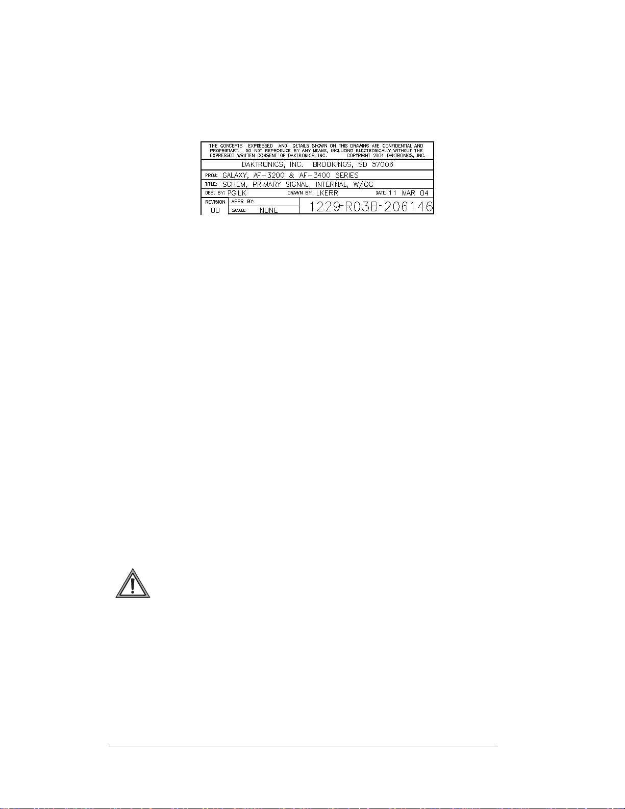
Figure 1 illustrates Daktronics drawing label. The lower-right corner of the drawing
contains the drawing number. The manual identifies the drawings by listing the last set of
digits and the letter preceding them. In the example below, the manual refers to the
drawing as Drawing B-206146. Appendix A contains all reference drawings.
Figure 1: Drawing Label
This manual shows all references to drawing numbers, appendices, figures, or other
manuals in bold typeface, as shown below:
“Refer to Drawing B-206146 in Appendix A for the power supply connections.”
Additionally, the manual lists drawings referenced in a particular section at the beginning
of that section as seen in the following example:
Reference Drawing:
Schem, Primary Signal, Internal, W/QC............................. Drawing B-206146
Daktronics builds displays for long life and that require little maintenance. However,
from time to time, certain display components need replacing. The Replacement Parts
List in Section 4.13 provides the names and numbers of components that may need
replaced during the life of the display. Most display components have a white label that
lists the part number. The component part number is in the following format: 0P-_ _ _ __ _ _ _ (circuit board) or 0A-_ _ _ _-_ _ _ _ (multi -component assembly).
Following the Replacement Parts List is the Exchange and Repair and Return
Programs in Section 4.14. Refer to these instructions if any display component needs
replacement or repair.
1.1 Safety Precautions
Important Safeguards:
1. Read an d understand these instructions before installing.
2. Be sure the display and external signal enclosures are properly grounded
with an earth ground electrode at the display.
3. Disconn ect power when servicing the display.
4. Do not modify the display structure or attach any panels or coverings to the
display without the written consent of Daktronics, Inc.
1-2
Introduction
Page 9

Note: This equipment has been tested and found to comply with the limits for a
lass A digital device, pursuant to part 15 of the FCC Rules. These limits are
C
designed to provide reasonable protection against harmful interference when the
equipment is operated in a commercial environment. This equipment generates, uses,
and can radiate radio frequency energy and, if not installed and used in accordance
with the instruction manual, may cause harmful interference to radio
communications. Operation of this equipment in a residential area is likely to cause
harmful interference. In such cases, the user will be required to correct the
interference at their own expense.
Modifications not expressly approved by the manufacturer could void the user's
thority to operate the equipment under FCC rules.
au
1.2 Network Concepts
The concept of using LED displays as a cost effective, high impact method of
communication is rapidly growing throughout many industries and businesses. The
reasons for this growth are many, but the need for additional features and complexity
of multiple display installations has emerged. Daktronics display systems have been
designed to meet those needs.
The common thread to most client requests is a means of programming and
ntrolling a group of displays from a central control point. Daktronics responded by
co
developing a powerful system of interconnecting and controlling displays. Great care
has been taken to design products that will satisfy a wide variety of installations.
Some of the design goals of these systems include the following:
• Easy trans
e ability to tell a display or group of displays in the network which
• Th
message should run
e ability to determine the status of any display on the network
• Th
e ability to control multiple display technologies on the same network
• Th
Tools required for mounting the display depend on the location and size of the
display. For some installations, it may be possible to use pre-terminated telephone
cables for use with the displays.
There are six network systems available: RS232, RS422, modem, fiber, radio and
hernet. They differ in the type of physical connections needed, the distance
Et
allowed, and the equipment used. A separate manual is provided for the type of
communication method ordered with your display. See Section 3.7 for the
communication manual ED numbers.
Up to 240 displays can exist on one network.
fer of messages
Introduction
1-3
Page 10
1.3 Display Overview
Reference Drawings:
Power Specs, AF-3400, **x**-64-A-P-*-Domestic....... Dra
Power Specs AF-3400, **x**-64-R-P-*-Domestic........ Dra
Shop Drawings.........................................................Ref
Daktronics 64 mm, AF-3400 Galaxy® displays are designed and manufactured for
performance, reliability, easy maintenance, and long life. The pixels have a 64mm
center-to-center spacing and LEDs (light emitting diodes). Each display section has
minimum 18-inch character height. An optional remotely mounted light sensor can
automatically dim the LEDs based on the ambient light levels. The configuration of
pixels depends on the model of display ordered.
Refer to the appropriate Sh
requirements for your model of display.
The Galaxy
®
model numbers are described as follows: AF-3400-RRCCC-64-X-P
RR
64
P
=
=
=
=
=
=
AF-3400
CCC
R or A
A typical display system consists of a Windows® based personal computer (PC)
running Venus
package that runs under Windows 98, ME, NT
an IBM
manual (ED13530) included on the installation CD for installation and operation of
the Venus
The displays are offered as single-face un
displays. They can become double-faced by mounting them back-to-back with a
second primary unit.
®
1500 software and one or more displays. Venus® 1500 is a software
®
-compatible computer. Refer to the Venus 1500 controller operator’s
®
1500 software.
op Drawings for the approximate size, weight, and power
Outdoor Louvered Galaxy Display
Number of Rows High (8, 16, 24, and 32)
Number of Columns Long (32, 48, 64, 80, 96, and 112)
64mm center-to-center pixel spacing
LED Color, R (Red) or A (Amber)
Primary
wing A-192935
wing A-192937
er to Appendix A
®
, 4.0, or 2000 operating systems on
its, which are single-sided, stand-alone
1-4
Introduction
Page 11
1.4 Component Identification
The following illustrations and definitions depict some of the more commonly
accessed Galaxy
®
display components. Because Daktronics occasionally alters
standard design to meet customer needs, the actual display design may vary slightly
from the illustrations below.
This is only a brief overview. Refer to Section 4 for detailed information on
maintaining and troubleshooting various display components.
Com Port: Connector on the back of the control computer. The COM port controls
the sign through a 9-pin serial connector.
Controller: The display’s controller is the “brains” of the display (refer to Figure 2).
The controller receives, translates, and activates the signal information from the
control computer to the appropriate pixels on the display.
Figure 2: Controller
Display Address: The display address is an identification number assigned to each
display of a network. It is set by rotating hex switches on the controller. The control
software uses the address to locate and com municate with each display. Displays that
are on the same network cannot have the same address.
Driver: Circuit board responsible for switching the intensity levels of the LEDs. One
driver mounts on the back of each 4x8 board of an 8x8 module.
Galaxy
signs.
LED (light emitting diode): Low energy, high intensity lighting units.
Introduction
®
: Daktronics trademarked name for LED monochrome or tri-colored matrix
1-5
Page 12
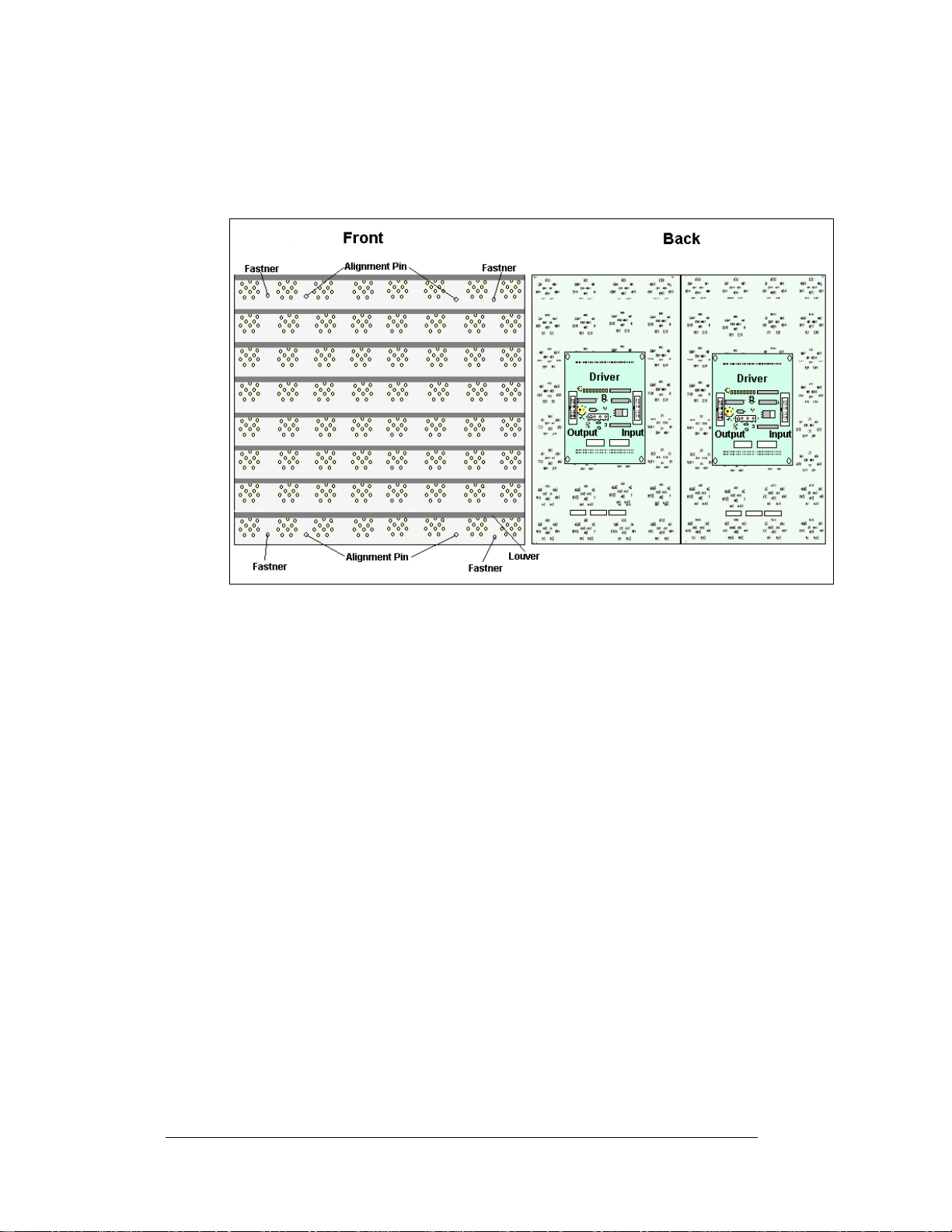
Louver: Black shade positioned horizontally above each pixel row. The louvers
increase the level of contrast on the display face and direct LED light.
Module: 64mm Galaxy
the louver assembly, two 4x8 pixel boards, and two drivers (refer to
®
modules are 8 pixels high by 8 pixels wide. They consist of
Figure 3).
Figure 3: 8x8 Amber Pixel Module (Front and Rear)
Network: Consists of multiple displays connected to each other.
Pixel: Cluster of LEDs. The number and color of the LEDs depends on display
application.
Pixel Board: The pixel board contains the LED clusters, which mount into the metal
face panel. A module driver is attached to the back of each 4x8 pixel board.
Power Supply: Converts AC line voltage from the load center to low DC voltage for
one or more module driver boards.
Primary: A primary display is a single-faced unit. The communication and
temperature input will be connected to this display. The light sensor is internally
mounted in this display. If two primary displays are used, the display signal and
temperature information is hardwired from display to display. Route the
interconnect cable through conduit when exposed to outdoor conditions.
1.5 Daktronics Nomenclature
To fully understand some Daktronics drawings, such as schematics, it is necessary to
know how those drawings label various components. This information is also useful
when trying to communicate maintenance or troubleshooting efforts.
1-6
Introduction
Page 13
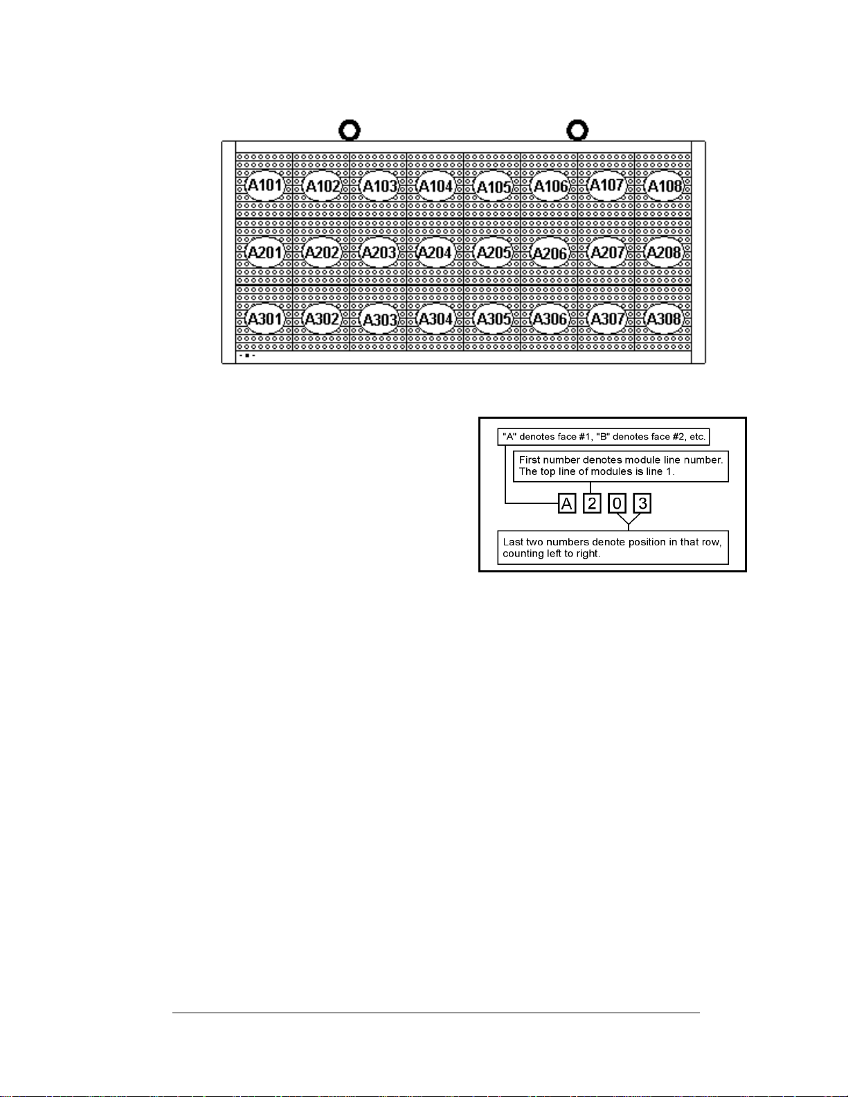
Figure 4: Module Numbering Example – 24x64 Front
A module is the building block of the
display. Each module measures 8 pixels
high by 8 pixels wide. By placing modules
side-by-side and on top of one another,
Daktronics can design and build displays
of any size. A person can easily remove
individual modules from the displays if
required.
Figure 4 illustrates how
Daktronics numbers modules on a Galaxy
display.
Figure 5 breaks down the module
numbering method.
In addition, various Daktronics drawings
may contain the following labeling formats:
• “TB_ _” shows a termination block for power or signal cable.
• “F_ _” denotes a fuse.
• “E_ _” signifies a grounding point.
• “J_ _” stands for a power or signal jack.
• “P_ _” represents a power or signal plug for the opposi t e jack.
Finally, drawings commonly have Daktronics part numbers. You can use those part
numbers when requesting replacement parts from Daktronics Customer Service.
Take note of the following part number formats:
®
Figure 5: Module Numbering
• “0P-_ _ _ _-_ _ _ _” gives the form of an individual circuit board, such as a
fiber optic board.
• “0A-_ _ _ _-_ _ _ _” represents an assembly, such as a circuit board and the
plate or bracket to which it mounts. A collection of circuit boards working
as a single unit may also carry an assembly label.
• “W-_ _ _ _” indicates a wire or cable. Cables may also carry the assembly
numbering format in certain circumstances. This is especially true of ribbon
cables.
• “F-_ _ _ _” signifies a fuse.
Introduction
1-7
Page 14

Most circuit boards and components within this display
carry a label that lists the part number of the unit. If the
Replacement Parts List in Section 4.13 does not list a
circuit board or assembly, use the label to order a
replacement.
Figure 6 illustrates a typical label. The part
number is in bold.
Figure 6: Typical Label
1-8
Introduction
Page 15

Section 2: Mechanical Installation
Note: Daktronics does not guarantee the warranty in situations where the display is not
constantly in a stable environment.
Daktronics engineering staff must approve an
of the display. If any modifications are made, detailed drawings of the changes must be
submitted to Daktronics for evaluation and approval, or the warranty may be void.
Daktronics is not responsible for installations or the structural integrity of support
tures done by others. The customer is responsible to ensure that a qualified structural
struc
engineer approves the structure and any additional hardware.
2.1 Mechanical Installation Overview
y changes that may affect the weather-tightness
Because every installation site is unique, Daktronics has no single procedure for
mounting the Galaxy
may or may not be appropriate for your particular installation.
®
displays. This section contains general information only and
A qualified installer must make all decisions regarding the mounting of this
display.
Read both the mechanical and electrical installati
before beginning any installation procedures.
2.2 Support Structure Design
Support structure design depends on the mounting methods, display size and weight.
Since the structure design is critical, only a qualified individual should mount the
display. Display height and wind loading are also critical factors. It is the customer’s
responsibility to ensure that the structure and mounting hardware are adequate.
Daktronics is not responsible for the installations or the structural inte gri t y of
support structures done by others.
The installer is responsible to ensure the mounting structure and hardware are
capable of supporting the display and agree with local codes.
Before beginning the installation proces s, verify the following:
• The mounting structure provides a straight and square frame for the display.
• The mounting structure supports the display without yielding at any
unsupported points after mounting.
• Clearance: 3 " of unobstructed space is available behind the display for
ventilation. 1¼" of unobstructed space is available above the top of the
display.
Correct any deficiencies b
efore installation.
on sections of this manual
Mechanical Installation
2-1
Page 16
2.3 Ventilation Requirements
Reference Drawings:
Shop Drawings.........................................................Refer to Appendix A
Fans mounted in the backsheets toward the top of the display allow for ventilation.
Maintain a minimum distance of 3" (7.62 cm) behind the display to maintain proper
airflow. Refer to the appropriate Shop Drawing for additional information.
If the display cabinet is shrouded or completely enclosed, allowances must be made
to compensate for the percentage of material covering the openings in the structure.
Failure to comply with these requirements voids the Galaxy® display warranty.
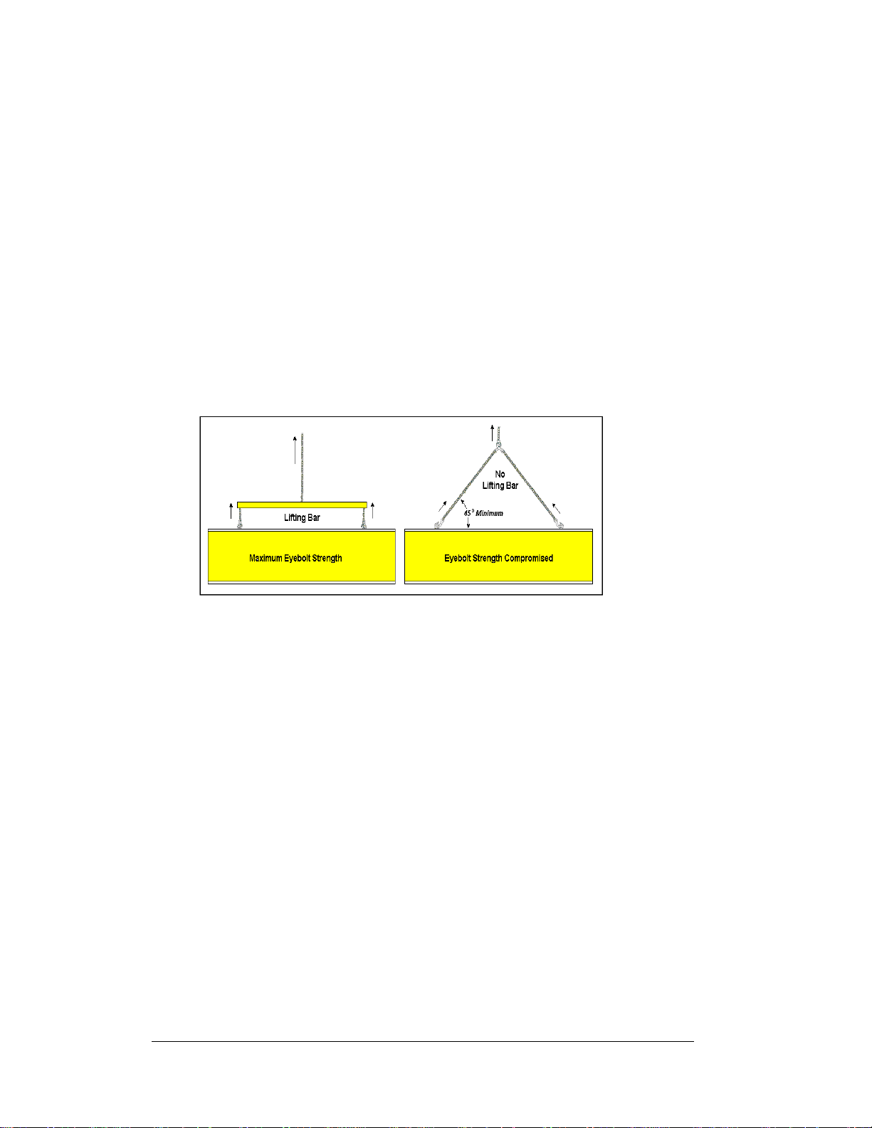
2.4 Lifting the Display
Figure 7: Lifting the Display (left; correct) and (right; incorrect)
The top of the display has eyebolts to lift the unit. Do not exceed the rated load of the
eyebolts. Refer to the information at the end of this section labeled Eyebolts to
determine the allowable load of the eyebolts shipped with the display.
Figure 7 illustrates both the correct (left example) and the incorrect (right example)
method of lifting a display. Lift the display as shown on the left, with the lifting bar.
Use every lifting point provided.
Do not attempt to permanently support the display by the eyebolts.
If you remove the eyebolts, adequately seal the holes using 13 bolts and sealing
washers, ½ inch in size. Silicone along the threads to ensure water does not enter the
display.
2.5 Display Mounting
Reference Drawings:
Shop Drawings.........................................................Refer to Appendix A
The method used to mount displays varies greatly from location to location. For this
reason, the manual covers only general mounting topics.
2-2
Mechanical Installation
Page 17

The installer is responsible to
codes and standards. The installer is also responsible for the mounting method
and hardware.
Before beginning the installation proces s, verify the following items:
ensure the installation will adequately meet local
• The mounting structure will provide a straight and square frame for the
display. Height variation in any four-foot horizontal section may not exceed
¼- inch.
• The mounting structure will not give way at any unsupported points after
the display is mounted.
The back of the display uses 3x2x3/8" steel clip angles at the locations shown in the
Shop Drawings. These angles assist in mounting the display. Remember to have all
mounted displays inspected by a qualified structural engineer.
The customer must ha
attachment points needed and the wall structure to ensure both meet all nationa l and
local codes. Daktronics recommends using all clip angles as attachment points.
ve a qualified structural engineer review the number of
1. Carefully uncrate the display. Look over all sides of the display for possible
damage during shipping.
2. Following the guidelines described in Section 2.4, lift the display into
position on the support structure using all provided eyebolts.
3. Weld or use ½" Grade-5 bolts and hardware to secure the clip angles to the
support structure as shown in Top View in the Shop Drawings. Refer to
Section 3 for information on routing power and sig nal .
4. For 40 and 48 high Sectional Displays Only: Remove lift eyes from the
bottom section. Using all lift eyes provided, lift the top section over the
bottom section. Align the holes as required for 5/8" hardware. Secure
sections using 5/8" hardware, as shown in Shop Drawings. Connect power
using the Mate-N-Lok
by routing the ribbon cable from the controller to the first driver in the row
of modules for the rows in the top section.
®
plugs provided with the display. Connect the signal
5. Upon completing the installation, carefully inspect the display for any holes
that may allow water to seep into the display. Seal any openings with
silicone. If eyebolts are removed on the top of the display, plug the holes
with bolts and the rubber sealing washers that were removed with the
eyebolts. Silicone the threads on the bolts.
2.6 Optional Temperature Sensor Installation
If an optional temperature sensor will be used with the display, see Appendix B for
mounting and signal connections.
Mechanical Installation
2-3
Page 18

Page 19
Section 3: Electrical Installation
Only a qualified individual should terminate power and signal cable within this
Daktronics display.
The Daktronics engineering staff must approve any changes made to the display. Before
altering the display, submit detailed drawings for the proposed modifications to the
Daktronics engineering staff for evaluation and approval, or the warranty will render null and
void.
3.1 Common Connectors in the Display
The power and signal connections in the displays use many
different types of connectors. Take special care when disengaging
any connector so as not to damage the connector, the cable, or the
circuit board.
When pulling a connector plug from a jack, do not pull on the wire
or cable; pull on the jack itself. Pulling on the wires may damage
the connector.
The following information presents some common connectors
encountered during display installation and maintenance.
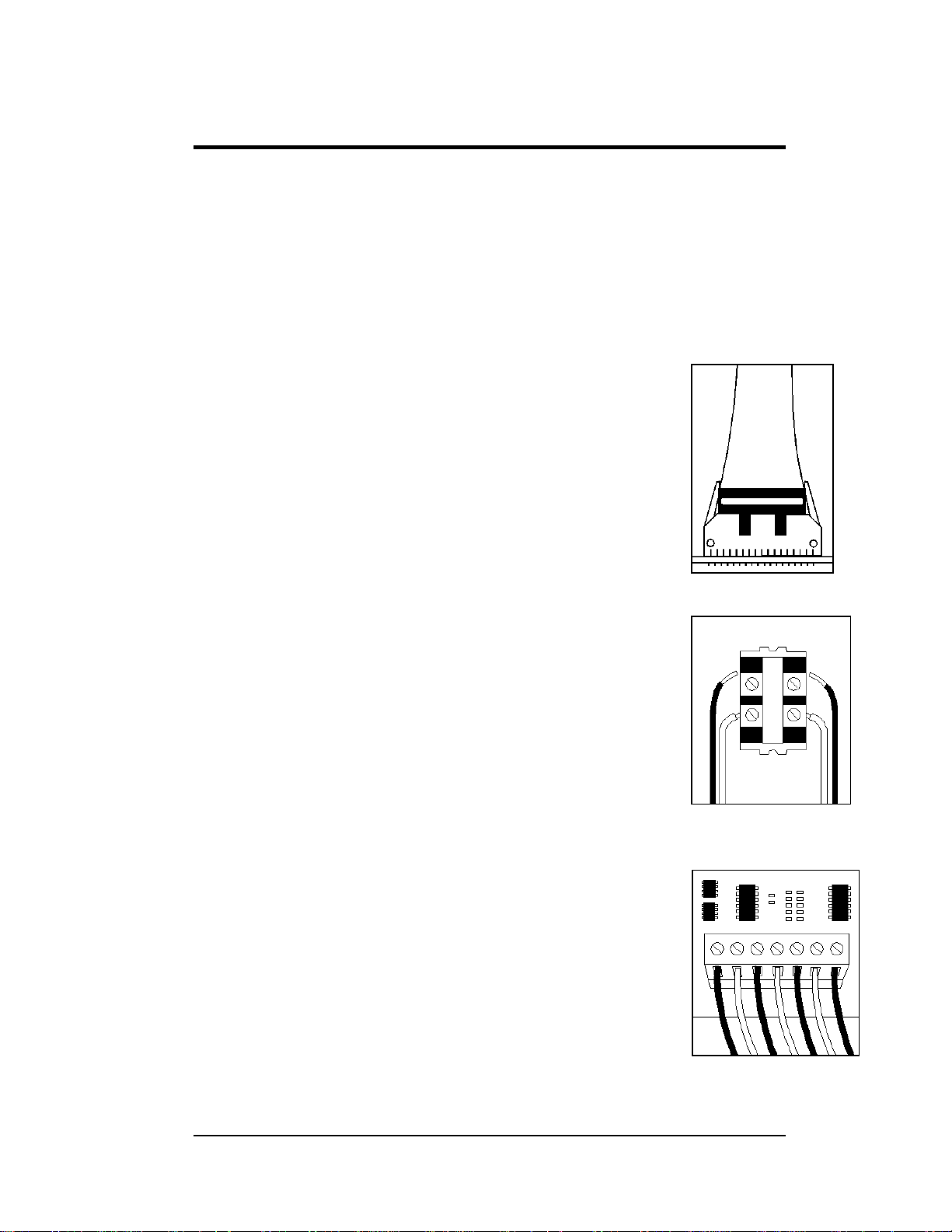
1. Ribbon Cable Connectors:
Figure 8 illustrates a typical ribbon connector. To
disconnect the ribbon cable, push the plastic clips on the
sides to unlock and remove the jack.
Before replacing a ribbon cable connector, spray it with
DeoxIT
may cause signal problems. In addition, apply a generous
amount of CaiLube
™
contact cleaner to remove any foreign matter that
™
protector paste to the plug before
inserting it into the jack. This paste protects both the plug
and the jack from corrosion.
2. Termination Blocks:
Termination blocks connect internal power and signal
wires to wires of the same type coming into the display
from an external source. Most signal wires come with
forked connectors crimped to the ends of the wire. Power
wires need to have one-half inch of insulation stripped
from the end of the wire prior to termination. Tighten all
screws firmly to ensure a good electrical connection. Refer
to Figure 9.
3. Phoenix™-Style Connectors:
Phoenix-style connectors, usually green, allow for signal
termination on circuit boards. Refer to Figure 10. Strip
one-quarter inch of insulation from the wire prior to
termination. To remove a wire, turn the above
Figure 8: Ribbon
Cable Connector
Figure 9: Termination
Block
Figure 10: Phoenix
Connector
Electrical Installation
3-1
Page 20
screw counterclockwise to loosen the connectors grip on
the wire. To insert a wire, push the bare wire into the
connector and turn the above screw clockwise to lock the
wire into place.
4. Phone Jacks (RJ11/RJ45 Connectors):
RJ connectors, as shown in Figure 11, are similar to the
telephone connectors found in homes. In order to remove
this plug from the jack, depress the small clip on the
underside of the plug.
Before replacing an RJ connector, spray it with DeoxIT
Figure 11: RJ45
Connector
™
contact cleaner to remove any foreign matter that may
cause signal problems. In addition, apply a generous
amount of CaiLube
™
protector paste to the plug before
inserting it into the jack. This paste will protect both the
plug and the jack from corrosion.
5. Mate-n-Lok
™
Connectors:
The white Mate-n-Lok connectors found in the displays
come in a variety of sizes. Figure 12 illustrates a five-pin
Mate-n-Lok connector. To remove the plug from the jack,
squeeze the plastic locking clasps on the side of the plug
and pull it from the jack.
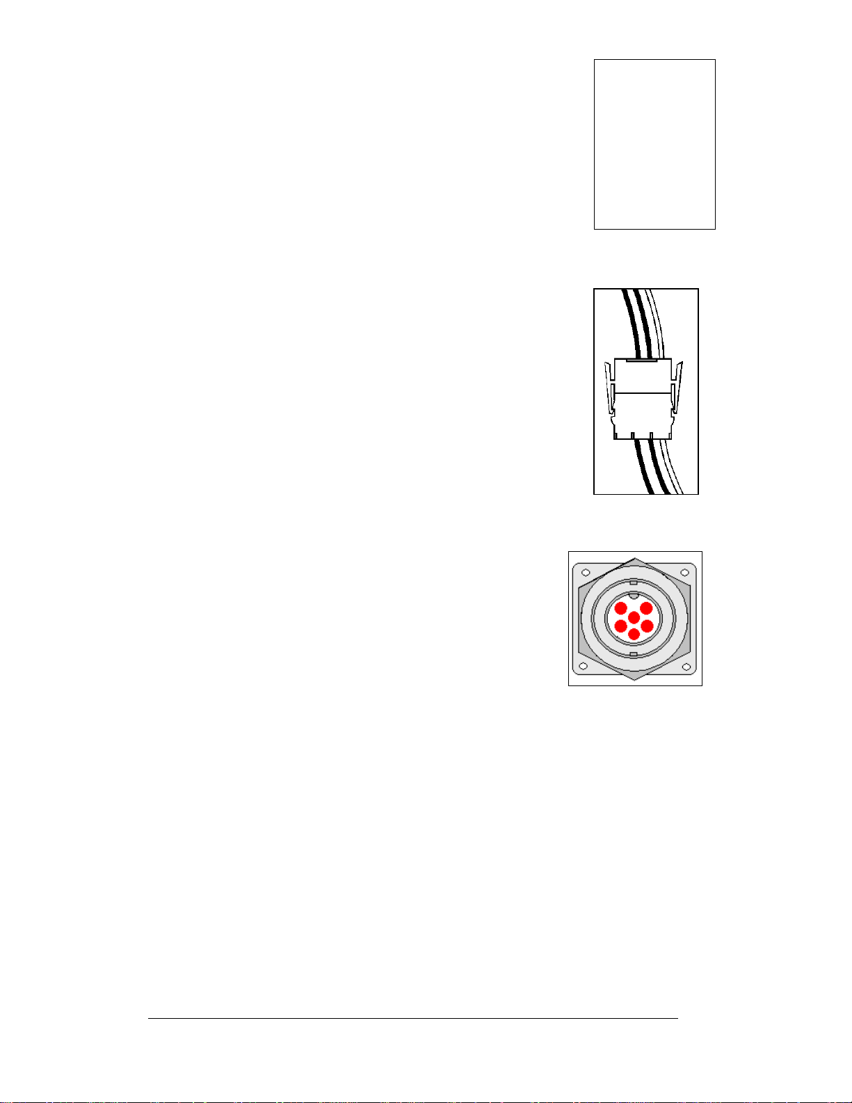
6. Quick Connect Jack:
The display uses quick connect jacks for the connection of
Figure 12: Maten-Loc Connector
the signal termination enclosure and the temperature
sensor. There is one quick connect input board with
three input jacks. The board is located on the back of
the display, and when the jacks are not used, the
attached dust cover should be kept closed.
To attach the cable to a jack, make sure to line up the
plug to match the jack, push the plug in, and then turn
the outer collar to lock in place. Figure 13
the 6-pin quick connect jack.
illustrates
Figure 13: RS232/6-pin
Quick Connect Jack
3-2
Electrical Installation
Page 21

3.2 Signal Termination Enclosures
In each communication method, the final connection will be from a provided weather
resistant enclosure to the display. For signal termination to the enclosure, see the
manual included in the box with the enclosure.
Note the following information when mounting the enclosure:
1. Be sure to m
prevent water from entering into the enclosure.
2. Mount the
inaccessible to vandalism.
quick connect cable will be connected to the signal termination enclosure
3. A
and will terminate to the back of the primary display – the length of the
cable is 25 feet.
4. The quick
or through the display pole to the display but is not required. The cable is
weather and sunlight resistant.
Note: Da
secured to protect it from weather or vandalism.
ktronics engineers strongly recommend that the quick connect cable be
5. Ear
th ground the enclosures that use wire signal cable – the resistance to
ground should be 10 ohms or less (a grounding electrode conductor is
attached to the enclosure to make the necessary earth ground connection)
ount the enclosure with the cables exiting from the bottom to
enclosure securely and if possible at a height or location
connect cable can be run from the enclosure through 2” conduit
3.3 Conduit
Reference Drawings:
Shop Drawings......................................................... Ref
Daktronics does not include the conduit. Refer to the Sh
locations of power and signal conduit. You must use separate conduit to route:
• Power
• Signal IN wires
• Signal OUT wires (if another display is being utilized)
Locate the conduit holes at the bottom right (rea
Punch or drill out the desired conduit openings. Be careful not to damage any
internal components. Attach the conduit, and then route the power and signal cables.
For displays with more than one face, signal and temperature connection between
splays is done with interconnect signal wiring. The signal output on the first
di
display will connect to the input on the second. The interconnect wiring is included
in the manual for the communication type. The interconnect wiring for the
temperature sensor is shown in Appendix B.
er to Appendix A
op Drawing for approximate
r view) of the back of the display.
Electrical Installation
3-3
Page 22
3.4 Preparing for Power/Signal Connection
Reference Drawings:
Shop Drawings.........................................................Refer to Appendix A
1. To create an opening for display power and interconnect signal cable in the
back of the display, punch or drill through the knockouts in the lower right
corner from the rear. Refer to the Shop Drawings for appropriate locations.
2. Rou te power to the display through a fused disconnect switch capable of
opening all ungrounded power con d uct or s. Inst all thi s di sconnect within the
line of sight of any personnel performing maintenance on the display. If the
disconnect is located out of sight of the display, it must be capable of being
locked in the open position.
3. Power conductors from the disconnect to the display should be routed
through conduit in agreement with local code. Run the power and signal
cables in a separate conduit.
4. Display power will terminate to the display at the power termination box
located behind the second module from the left when viewed from the front.
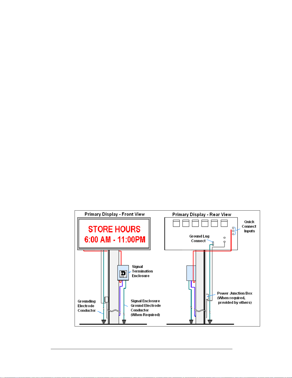
5. Conn ect the grounding electrode conductor to the display at the ground lug.
6. An enclosure is provided with the display for termination of signal. (If the
installation of the display does not allow for the use of the enclosure, the
manual for the communication type shows the alternate termination method
for the signal.)
7. Signal into the enclosure must be routed through conduit. The size of the
knockouts in the enclosure requires the use of ½” conduit.
8. The quick connect cable from the enclosure to the display can be routed
through conduit or the display pole.
9. Note: Daktronics engineers strongly recommends that the quick connect
cable be secured to protect it from weather of vandalism.
3-4
Figure 14: Primary Display with Enclosure
Electrical Installation
Page 23

3.5 Power
Reference Drawings:
Panel Board Layout, AF-3400-64mm..........................Drawing A-192369
Power Specs, AF-3400-**x**-64-A-P-*-Domestic........Drawing A-192935
Power Specs, AF-3400-**x**-64-R-P-*-Domestic........Drawing A-192937
Refer to Drawings A-192935 and A-192937 for voltage and current requirements for
the display size. The display will use either a 120/240VAC single-phase power or
120/208 three-phase power source.
Do not connect the display to any voltage other than that listed on the
Daktronics product label.
Proper power installation is imperative for proper display operation. The following
sub-sections give details of display power installation.
Grounding
This sign is intended to be installed in accordance with the requirements of
Article 600 of the National Electrical Code and/or other applicable local codes.
This includes proper grounding and bonding of the sign.
Displays must be grounded according to the provisions outlined in Article 250 of the
National Electrical Code
less. Verification of ground resistance can be performed by the electrical contractor
who is performing the electrical installation. Daktronics Sales and Service personnel
can also perform this service.
The display system must be connected to earth-ground. Proper grounding is
necessary for reliable equipment operation. It also protects the equipment from
damaging electrical disturbances and lightning. The display must be properly
grounded or the warranty will be void.
A grounding lug is included on the back of the display for easier connection of the
grounding electrode.
®
. Daktronics requires a resistance to ground of 10 ohm s or
Figure 15: Display Grounding
Electrical Installation
3-5
Page 24

A minimum of one grounding electrode must be installed for each display face. The
grounding elec
trode is typically one grounding rod for each display face. Other
grounding electrodes as described in Article 250 of the National Electric Code may
be used. Daktronics requires that the resistance to ground be 10 ohms or less. If the
resistance to ground is higher than 10 ohms, it will be necessary to install additional
grounding electrodes to reduce the resistance. The grounding electrode should be
installed within 25 feet of the base of the display. The grounding electrode must be
connected to the ground terminal on the back of the display.
This grounding electrode must be installed in addition to the equipment-grounding
nductor that should be part of the power installation. The material of an earth-
co
ground electrode differs from region to region because of conditions present at the
site.
The support structure of the display cannot be use
d as an earth ground electrode. The
support is generally embedded in concrete, and if in earth, the steel is either primed
or it corrodes, making it a poor ground. The grounding system and grounding
electrodes must be installed according to Article 250 of the National Electrical Code
and any applicable local codes.
Power Installation
There are two considerations for power installation: installation with ground and
neutral conductors provided and installation with on ly a neutral conductor provided.
For these displays, installation with ground and neutral conductors provided is used.
Electrical installations must be performed by qualified personnel. Unqualified
ersonnel should not attempt to install the electrical equipment. Serious danger to
p
equipment and personnel could occur if equipment is improperly installed.
3-6
Installation with Ground and Neutral Conductors Provided
For this type of installation, the power cable must con
tain an isolated earth-ground
conductor. Under this circumstance, do not connect neutral to ground at the
disconnect or at the display. This would violate electrical codes and void the
warranty. Use a disconnect so that all hot lines and neutral can be disconnected. The
National Electrical Code requires the use of a lockable power disconnect within sight
of or at the display.
Power Connection
Display power is connected to the power termination panel in the display. Complete
the following steps to terminate the hot, neutral, and ground wires to the termination
panel. Refer to Drawing A-192369 for assistance.
ith a #2" screwdriver, release the four screws that hold the module in
1. W
place. The module will pull forward and out from the display.
sconnect the power and signal cables from the back of the module.
2. Di
ute the power cable through conduit to the back of the display – use one
3. Ro
of the ½” knockouts for access, being careful not to damage any internal
components.
4. Mak
e the following connections as shown in Figure 16 for a single phase
display:
120/240 (Three wires plus Ground)
TB41
E41 Ground
1 Line 1 (Hot)
2 Line 2 (Hot)
3 Neutral
Electrical Installation
Page 25

Figure 16: Power Termination Box
5. Make the following connections as shown in Figure 16 for a three phase
display:
120/208 (Four wires plus Ground)
TB41
4 Neutral
E41 Ground
1 Phase A
2 Phase B
3 Phase C
6. Power needs to be connected to all display faces.
Main Disconnect
The National Electrical Code requires the use of a lockable power disconnect near
the display. Provide a lockable disconnect switch (knife switch) at the display
location so all power lines can be completely disconnected. Use a disconnect to
disconnect the hot lines and the neutral. Mount the main disconnect at or near the
point of power supply connection to the display. Provide a main disconnect for each
supply circuit to the display.
You must locate the means of disconnection in a direct line of sight from the display
or outline lighting that it controls. This requirement provides protection by enabling
a worker to keep the disconnecting means within view while working on the d isplay.
Exception: You may locate the disconnecting means that are capable of being
locked in the open position elsewhere.
Electrical Installation
3-7
Page 26

3.6 Signal Termination from Computer to Display
The 64mm, AF-3400 Mono display is designed for quicker signal and power
connection to the display and between displays.
• Signal will terminate to a watertight enclosure, which connects to the
primary display using a quick connect cable.
• Mounting the temperature sensor to the display structure and at least one
foot away from the display is preferred – terminate it to the primary display
with a quick connect cable (DO NOT mount the temperature sensor
between displays, or anywhere the airflow is restricted).
• If two primary displays are being used, signal and temperature sensor wires
will be connected between the controllers on each display.
A separate manual is provided for explaining the connection to the signal termination
enclosure. There are seven different methods of communication; your manual will
be one of these types:
Communication
Type
RS232
RS422
Serial Fiber
Radio
Modem
Wire Ethernet
Fiber Ethernet
Communication
Manual ED#
ED-14739
ED-14742
ED-14743
ED-13932
ED-14744
ED-14745
ED-14746
3.7 Signal Termination between Displays
Reference Drawings:
Controller, Galaxy, 8 conn., J1087.............................. Drawing B-177838
The connection between display controllers requires a 4-conductor shielded cable for
signal. One end will connect at the “RS422 OUT” 6-position controller board
terminal block (TB3) on the first primary display, and terminate on the “RS422 IN”
6-position controller board terminal block (TB2) on the second display. Refer to
Drawing B-177838 for terminal block locations. The interconnect signal wiring
between displays is shown in Figure 17.
A cable will also need to be routed for connection between displays for the
temperature sensor if one is being used. See Appendix B for the necessary wiring of
the temperature sensor.
Primary - RS422
Out (TB3)
Pin 1 (GND) Shield Pin 6 (GND)
Pin 2 (D2OUT-N) Red Pin 5 (D1IN-N)
Pin 3 (D2OUT-P) Black Pin 4 (D1IN-P)
Pin 4 (D2IN-N) Green Pin 3 (D1OUT-N)
Pin 5 (D2IN-P) White Pin 2 (D1OUT-P)
Pin 6 (Shield) Pin 1 (Shield)
Field Cabling
Secondary - RS422
IN (TB2)
3-8
Electrical Installation
Page 27

Display-to-Display RS422 Interconnection
Figure 17: RS422 Interconnection
3.8 Optional Temperature Sensor Installation
If you are using an optional temperature sensor with your display, see Appendix B
for mounting and signal connections.
3.9 First Time Operation
When first operated, the display will run through an initialization in which it will
display the following:
1. Product Name (Galaxy®)
2. Display Size (Row x Column)
3. Shading (64 Mono)
4. Boo tloader Version (OS X.XX)
5. Firmware Number (ED13305)
6. Firmware Revision (Rev X.XX)
7. Hardware Address (HW:XX)
8. Software Address (SW:XX)
9. IP Address: ((default) 172.16.192.25)
10. Subnet Msk: ((default) 255.255.0.0)
11. COM1 Configuration (C1:V15) ((Modem C1:V15) If a Modem is present)
12. COM2 Configuration (C2:RTD)
13. Socket 3001: (IP 3001: V15)
14. Socket 3002: (IP 3002: RTD)
15. Line Frequency (CLK: AUTO (60))
16. Display Name Description (Galaxy Row x Column)
Electrical Installation
3-9
Page 28

Page 29

Section 4: Maintenance and
Troubleshooting
Important Notes:
1. Disconnect power before performing any repairs or
maintenance work on the display!
2. Only qualified service personnel may acces s internal display
electronics.
3. The Daktronics engineering staff must approve ANY changes
made to the display. Before altering the display, you must
submit detailed drawings for the proposed modifications to
the Daktronics engineering staff for evaluation and approval,
or the warranty will be void.
4.1 Maintenance and Troubleshooting Overview
Daktronics Galaxy® AF-3400, 64mm series mono displays are front accessible;
meaning access to the internal components can be gained only from the front of the
display.
This section provides the following Galaxy
• Signal Routing Summaries give a basic explanation of the signal travel
through the display.
• Power Routing Summaries show a basic explanation of the power travel
through the display.
• Service and Diagnostics offer instructions for removing va ri o us di spl ay
components and explain the functions of circuit board connectors and the
meanings of any diagnostic LEDs.
• Maintenance lists a number of steps to take to keep this Galaxy
safe, working order.
• Troubleshooting presents some possible display malfunctions and provides
a number of possible causes for that malfunction.
• Replacement Parts List includes the part description and number of
display components that could need replacing during the life of this display.
• Daktronics Exchange and Repair and Return Programs explain the
Daktronics component return policy.
• Frequently Asked Questions lists some general information regarding the
Galaxy 3400 Series displays.
Note: A single pixel flashing in the lower right hand corner of the display indicates
that the display has power, but no messages are currently running.
®
display information:
®
display in
4.2 Signal Summary
The signal routing for the display can be summarized as follows:
1. Data from the controller computer, which runs Venus
travels via RS232, RS422, modem, fiber optic cable, radio signal or
Ethernet to the signal termination enclosure at the primary display.
2. From the signal enclosure, signal is sent to the primary display via a quick
connect cable.
Maintenance and Troubleshooting
®
1500 software,
4-1
Page 30

3. From the quick connect input bo ard, the signal is transferred to the display’s
controller via a 20-conductor ribbon cable.
4. From the controller, the signal then travels over 20-conductor ribbon cables
from the controller (J11 through J18 provides signal out) to J2 on the driver
of the first row of modules in the display.
5. The data ex ists at J1 and is then relayed to J2 of the next driver board and so
on, traveling down the entire row of modules. The drivers use this display
data to control the LEDs.
6. From the first display controller, signal can also be transferred to another
display controller in a second display.
7. Refer to Figure 18
for the signal summary in a primary display.
Figure 18: Primary Display Signal Summary
4.3 Power Summary
The following describes the internal display power routing for the display:
1. Incoming power terminates at the panel board.
2. +12.5VDC power supplies power to the modules in both the monochrome
red and amber displays.
4-2
Maintenance and Troubleshooting
Page 31

4.4 Display Access
Display access for all 64mm displays is from
the front. To open the display:
1. Locate the four screws that hold the
module in place. Two are on top of
the module and two are on bottom of
the module.
2. W ith a #2 Phillips screwdriver, loosen
the four screws as shown in Figure
19. The screws are part of the module
and will not be removed.
3. Interior display components may be
accessed, or the module driver or LED
board may be removed from the
module itself.
When closing a display, reverse the previous
steps and take note of the following points:
• The weather-stripping on the back edge of the module is intact and in good
condition for preventing water from seeping into the display.
• The module screws are tight to create a water resistant seal around the edge
of the module. The module must be firmly seated against the display to shed
water.
Figure 19: Removing a Module
4.5 Service and Diagnostics
Reference Drawings:
Schematic; Power Supply Configurations....................Drawing A-191636
Shop Drawings......................................................... Refer to Appendix A
The following sub-sections address servicing of the below display components:
• Line filter and ground bar
• Modules, drivers, and power supplies
The sub-sections also address any diagnostic LEDs, fuses, and signal/power
connectors found on the components.
The Shop Drawings denote the components as follows:
Component… Denoted As… Location…
Modules 0A-1308-0002 or
Power Supplies 0A-1307-0500
0A-1308-0003
0A-1307-0501
0A-1307-0502
0A-1307-0503
0A-1307-0511
0A-1307-0512
Over entire face of the display
Behind the modules; refer to
Drawing A-191636 and the Shop
Drawings.
Maintenance and Troubleshooting
4-3
Page 32

Line Filter
You can replace the filter by labeling and removing all connecting wires, and then
releasing the attachment hardware.
Figure 20: Power Term Panels
Modules and Drivers
An 8x8 module consists of louvers and two 4x8 LED display boards, each with a
driver mounted to the display board. Refer to Section 4.4 to open a display and
access the LED display boards and the drivers.
Each 4x8 LED board is a circuit board with 32 LED pixel clusters mounted directly
on it. Each LED board is removable from the 8x8 module. To remove an LED board
from the module:
1. Open the display as described in
Section 4.4.
2. Disconnect the power and signal
connector from the driver on the
LED board you wish to replace.
3. Remove the four nuts holding the
LED board to the louver assembly.
4. Remove the 5/16” nut that holds the
driver to the LED board, and gently
pry the driver from the LED board.
(A ¼” hex screw can be removed
from the front of the LED board to
remove the driver and the stand-off.)
5. Reverse the above procedure to
install a new pixel board.
4-4
Figure 21: Driver Board
Maintenance and Troubleshooting
Page 33

The driver is a circuit board responsible for switching the intensity levels of the
LEDs. One mounts on the back of each module. To remove a driver board:
1. Open the display as described in Section 4.4.
2. Disconnect all power and signal connections from the driver board.
3. Remove the one #6 nut holding the board in place.
4. Gently lift the board from the display.
5. Reverse the above procedure to install a new driver board.
Controller
Reference Drawings:
Controller, Galaxy, 8 conn., J1087...............................Drawing B-177838
The controller sends data to the modules. Refer to the signal summary in Section 4.2
for more information, and refer to the component location drawings for the position
of the controller board. Figure 22 and Drawing B-177838 illustrate a typical
controller.
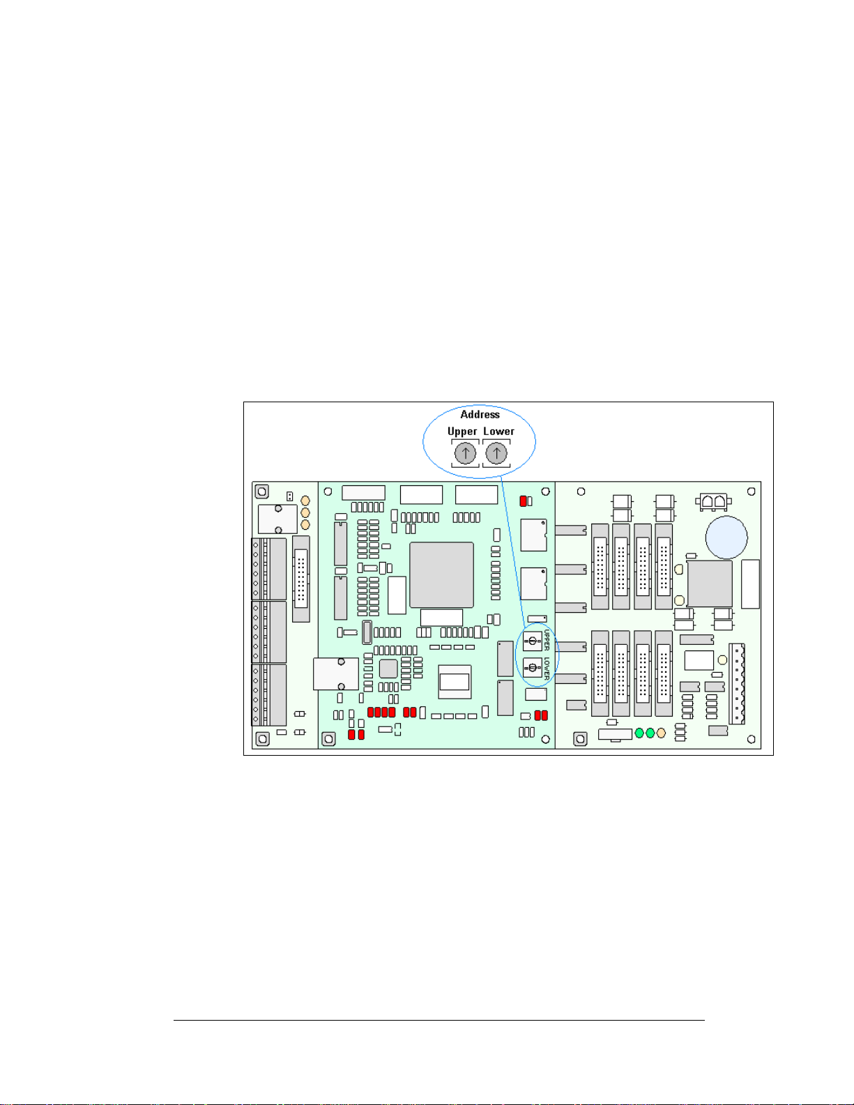
Figure 22: Controller
The rotary switches set the hardware address, which the software uses to identify that
particular display. When replacing a controller board, be sure to set the rotary
switches in the same address configuration as the defective controller. Each
controller in a network needs a unique address.
Note: Setting the rotary switches to address 0 (set the switches to 0 by rotating them
counterclockwise until the arrow points to 0) can activate a test mode. The display's
power must be turned off and then turned back on to run the test mode.
Complete the following steps to remove the controller from the display:
1. Open the display as described in Section 4.4.
Maintenance and Troubleshooting
4-5
Page 34

2. Disconnect pow er.
3. Remove all power and signal connections from the board. “Locked”
connectors are released by pushing apart the latches, and then carefully
pulling them from the jack. When replacing the board, it is helpful to have
the cables labeled as to which was removed from which connector.
4. Remove each of the six screws holding the board in place.
5. Follow the previous steps in reverse order to install a new controller board.
Address Upper Lower Address Upper Lower
Test Mode 0 0 10 0 A
1 0 1 11 0 B
2 0 2 12 0 C
3 0 3 13 0 D
4 0 4 14 0 E
5 0 5 15 0 F
6 0 6 16 1 0
7 0 7 17 1 1
8 0 8 … … …
9 0 9 240 F 0
Controller Address Settings
Four diagnostic LEDs are located on the controller; the table below shows what each
LED denotes:
CPU
LED Color Function Operation
DS1 Red CAN TxD Flashes when controller is transmitting CAN information.
DS2 Red CAN RxD Flashes when controller is receiving CAN information.
DS3 Red System Reset Off when controller is functioning properly. Flashes at 1.5-
second rate if controller is not resetting the watchdog timer.
DS4 Red Run A steady flash indicates the controller is running properly.
Normal flash rate is about once per second.
DS5 Red U15
Programmed
DS7 Red Link On when Ethernet interface is in the link-up condition.
DS8 Red Speed On when the Ethernet interface is at 100Mbps. Off when
DS9 Red Duplex On when the Ethernet interface is at full duplex. Off when
DS10 Red Collision Flashes when the Ethernet interface detects a collision in
DS12 Red +2.5V On when +2.5V power supply is functioning.
DS13 Red +3.3V On when +3.3V power supply is functioning.
On when U15 contains a valid logic program.
Flashes when the Ethernet chip detects transmits or
receives activity.
the Ethernet interface is at 10Mbps.
the Ethernet interface is at half-duplex.
half-duplex.
Product Board
LED Color Function Operation
DS1 Green +5V On when +5V power supply is functioning.
DS2 Green +3.3V On when +3.3V po wer supply is functi oning.
DS3 Yellow COM1 TxD Flashes when transmitting serial information.
4-6
Maintenance and Troubleshooting
Page 35

DS4 Yellow COM1 RxD Flashes when receiving serial information.
DS5 Yellow Light Flashes when receiving signal from light sensor
DS6 Yellow Com 2 RX2 Normal state is ON. When connected to receive RTD
input, the LED will be OFF. The LED flashes when
receiving signal from RTD input device.
Temp Sensor
LED Color Function Operation
DS1 Green +5V On when +5V power supply is functioning.
DS2 Red Run A steady flash indicates the controller is running correctly.
Normal flash rate is about once a second. Flashes faster
when the sensor is transmitting temperature or light
information.
Power Supplies
Reference Drawings:
Schematic, Power Supply Configurations
Power Supply Wiring Drawings
................................Refer to Appendix A
The LED power supplies are identified as assemblies in the Power Supply Wiring
Drawings:
A-1307-0502/0503 for six amber 8x8 modules (12, 4x8 LED boards)
1. 0
2. 0A
3. 0A-1307-0511/0512 for four
4. 0A
Complete the following steps to remove a power supply from the display:
1. Ope
2. Re
3. Disconnect all the wi
4. Re
5. Fo
6. Verify
-1307-0501 for four amber 8x8 mod ule s (8, 4 x8 LED bo ards)
red 8x8 modules (8, 4x8 LED boards)
-1307-0500 for two red or amber 8x 8 m odul es (4, 4x8 LED boards)
n the display as described in Section 4.4.
move the module directly in front of the failed power supply.
res connected to the power supply.
move the hardware holding the power supply in place to free the unit.
llow these steps in reverse order to install a new power supply.
power supply voltage.
....................Drawing A-192369
4.6 Ventilation Systems
Check ventilation fans after 1,500 hours of operation and every 1,500 hours after that
to ensure the display cools properly. Check fans more often if the display is located
in a dusty or harsh weather environment (i.e. along a gravel road with dust laden air).
• 1,500 hours is equivalent to 83 days, if the display operates for 18 hours a
day with the power to the display disconnected when not in use.
• 1,500 hours is equivalent to 62 days, if the display runs non-stop for 24
hours a day.
Attention: Shu
when the display is not operating exposes electrical components to excess
condensation, which shortens their life.
Maintenance and Troubleshooting
t off power to the display when it is not in use. Leaving the power on
4-7
Page 36

Each time you open the display, take a minute to inspect the fans:
• Check the fan blades for dirt and debris. If the fan blades have a large
accumulation of dirt and debris, change the filters more often. Keep the fan
blades clean to maintain fan efficiency and ensure proper cooling.
• Spin the fan blades with a pen or pencil to ensure that the bearings are free
and the fan is still in balance.
To check the operation of the fans:
• Hold your hand or a piece of light paper beneath the display to detect air
movement. If the operation of a fan is questionable, a fan-test should be
performed.
• Press button on the internal thermostat and ensure they run freely.
• If the fan does not turn or does not operate smoothly, replace it.
4.7 Thermostats
Reference Drawings:
Shop Drawings.........................................................Ref
A thermostat controls when the ventilation fans operate in the display. Refer to the
correct Sh
when the inside of the display reaches 85° F (29° C) and turn off at 70° F (21° C).
op Drawing for the location of the thermostat. The ventilation fans turn on
er to Appendix A
4.8 Display Maintenance
Perform a yearly inspection to maintain safe and dependable display operation. This
inspection should address the following issues:
• Loose Hardware
Verify fasteners, such as bolts and riv
tighten, and replace fasteners as required.
• Excessive Dust Buildup
Occasionally it may be necessary to vacuum the inside of the display
inet to remove dust/dirt buildup that may interfere with airflow.
cab
• Water Intrusion – Water Stain Marks
Water can enter the display where weather-stripping has come loose or
eriorated, where fasteners have come loose allowing gaps in the panels,
det
or where moisture may be entering around hardware. Check electronic
components for signs of corrosion.
• Corrosion
Check the paint; look for possible corrosion, especially at footings,
uctural tie points, and ground rods.
str
If you notice any of the above conditions, take action to correct the situation.
ets, have not come loose. Check,
4-8
Maintenance and Troubleshooting
Page 37

4.9 Weather-Stripping
To ensure the display is weather resistant, Daktronics provides weathe r-stripping
around the entire display and around each module. The weather-stripping must be
properly installed at all times or water may leak into the display, damaging the
components.
4.10 Troubleshooting
This sub-section contains some symptoms that may occur in the displays. This list
does not include every possible symptom, but does represent common situations that
may occur.
Symptom/Condition Possible Cause/Remedy
One or more LEDs on a single
module fail to light.
One or more LEDs on a single
module fail to turn off.
A section of the display is not
working. The section extends all
the way to the right side of the
display.
One row of modules does not
work or is garbled.
A group of modules, which share
the same power supply
assembly, fail to work.
Entire display fails to work. • Check for proper line voltage into the
Temperature always reads -196
degrees F.
Sign is stuck on bright or dim.
Maintenance and Troubleshooting
• Replace/check cables on the module.
• Replace LED board.
• Replace the driver.
• Replace/check cables on module.
• Replace LED board.
• Replace the driver.
• Replace/check the ribbon cable.
• Move/replace the first driver on the left
side of the first module that is not
working.
• Move/replace the second driver that is
not working.
• Check/replace the power supply
assembly on the first module that is not
working.
• Move/replace first driver
• Replace controller.
• Check the fuses in the power
termination box.
• Check power supply voltage.
• Check/replace ribbon cables.
• Replace the power supply assembly.
power termination panel.
• Check fuse in power termination box.
• Check/replace the ribbon cable from
the controller to the driver.
• Check the voltage settings on the
power supplies.
• Replace the controller.
• Verify proper use of the software in the
operation manual.
• Communicate to display directly using
a laptop.
• Check/replace the signal cable to the
controller.
• Check temperature sensor
connections.
• Replace the temperature sensor.
• Replace the controller.
• Check Manual/Auto dimming in Venus
1500 software.
4-9
Page 38

• Check that the address on the light
detector is set to address 2
• Check light detector cable.
• Check light detector for obstructions.
• Replace the light detector.
• Replace the controller.
4.11 Initial Operation Information
When first operated, the display will run through an initialization in which it will
display the following:
1. Product Name (Galaxy®)
2. Display Size (Row x Column)
3. Shading (64 M on o )
4. Bootloader Version (OS X.XX)
5. Firmware Number (ED13305)
6. Firmware Revision (Rev X.XX)
7. Hardware Address (HW:XX)
8. Software Address (SW:XX)
9. IP Address: ((default) 172.16.192.25)
10. Subnet Msk: ((default) 255.255.0.0)
11. COM1 Configuration (C1:V15) ((Modem C1:V15) If a Modem is present)
12. COM2 Configuration (C2:RTD)
13. Socket 3001: (IP 3001: V15)
14. Socket 3002: (IP 3002: RTD)
15. Line Frequency (CLK: AUTO (60))
16. Display Name Description (Galaxy Row x Column)
4.12 Replacement Parts List
The following table contains some of the items in this display that may need to be
replaced over time. Many of the parts within the display also list their part numbers
on labels affixed to them.
To prevent theft, Daktronics recommends purchasi
manuals and replacement/spare parts.
Part Description Part Number
Controller 0A-1229-0013
Light Detector 0P-1247-0002
Digital Temp Sensor 0P-1247-0008
Quick Connect Interface, Input 0P-1229-2004
Thermostat Enclosure 0A-1213-4024
Ribbon Assy, 20 Pos., 18”, Mod. to Mod. W-1387
Amber Pixel Board (Check display BOM) 0P-1261-0005
Red Pixel Board (Check display BOM) 0P-1261-0003
Red Driver Board 0P-1308-0001
Amber Driver Board 0P-1308-0004
Power Supply Amber/Red, 2 Mod. (A-1555), w/harness 0A-1307-0500
Power Supply, Amber, 4 Mod., (A-1648), w/harness 0A-1307-0501
ng a lockable cabinet to store
4-10
Maintenance and Troubleshooting
Page 39

Power Supply, Amber, 6 Mod., (A-1648) w/harness 0A-1307-0502
Power Supply, Red, 4 Mod., (A-1555), w/harness 0A-1307-0511
Fan; 110CFM, 115VAC, 17W, 60Hz, 4.5” B-1053
Transformer, 120 VAC Input T-1119
Transformer, 240 VAC Input T-1121
Controller Output Ribbon Cable Chart
Display Height (0A-1000-****) Line/
Plug
1 (P11) 0018 0020 0022 0025 0026 0088
2 (P12) 0018 0020 0022 0025 0026
3 (P13) 0018 0020 0022 0025
4 (P14) 0018 0020 0022
5 (P15) 0018 0020
6 (P16) 0018
8 16 24 32 40 48
4.13 Daktronics Exchange and Repair and Return
Programs
To serve customers' repair and maintenance needs, Daktronics offers both an
Exchange Program and a Repair and Return Program.
Daktronics' unique Exchange Program is a quick, economical service for replacing
components in need of repair. If a component fails, Daktronics sends the
key
customer a replacement, and the customer, in turn, sends the failed component to
Daktronics. This not only saves money but also decreases display downtime.
Daktronics provides these plans to ensure users get the most from their Daktronics
roducts, and it offers the service to qualified customers who follow the program
p
guidelines explained below. Please call the Help Desk – 877-605-1113 – if you have
questions regarding the Exchange Program or any other Daktronics service.
When you call the Help Desk, a trained service technician will work with you to
lve the equipment problem. You will work together to diagnose the problem and
so
determine which replacement part to ship. If, after you make the exchange, the
equipment still causes problems, please contact our Help Desk immediately.
If the replacement part fixes the problem, package
and wrapping in which the replacement part arrived, fill out and attach the enclosed
UPS shipping document, and return the part to Daktronics. In most circumstances,
you will be invoiced for the replacement part at the time it is shipped. This bill,
which represents the exchange price, is due when you receive it.
Daktronics expects immediate return of an exchange part if it does not solve the
problem
damaged due to acts of nature or causes other than normal wear and tear.
If you do not ship the defective equipment Daktronics within 30 working days from
the invoice
outright (with no exchange), and you will be invoiced for it. This second invoice
represents the difference between the exchange price and the full purchase price of
the equipment. The balance is due when you receive the second invoice.
. The company also reserves the right to refuse equipment that has been
date, Daktronics assumes you are purchasing the replacement part
the defective part in the same box
Maintenance and Troubleshooting
4-11
Page 40

If you return the exchange equipment after 3
you will be credited for the amount on the second invoice, minus a restocking fee.
To avoid a restocking charge, you must return the defective equipment within
30 days from the invoice date.
Daktronics also offers a Repair and Return Program for items not subject to
nge.
excha
Return Materials Authorization: To
representative prior to shipment to acquire a Return Material Authorization (RMA)
number. If you do not have a local representative, call the Daktronics Help Desk for
the RMA. This expedites repair of your component when it arrives at Daktronics.
Packaging for Return: Packag
in shipment. Electronic components such as printed circuit boards should be installed
in an enclosure or placed in an antistatic bag before boxing. Please enclose your
name, address, phone number, and a clear description of symptoms.
This is how to reach us:
Mail:
PO Box 5128
331 32nd Ave
Phone:
Fax: 6
E-mail: h
Customer Service, Daktronics Inc.
Brookings SD 57006
Daktronics Help Desk: 877-605-1113 (toll free)
or 605-697-4034
05-697-4444
elpdesk@daktronics.com
e and pad the item well so that it will not be damaged
0 working days from the invoice date,
return parts for service, contact your local
4-12
Maintenance and Troubleshooting
Page 41

Appendix A: Reference Drawings
Refer to Section 1.1 for information on reading drawing numbers. This appendix lists the
following drawings in numerical order by size (A, B, etc.)
Schematic; Power Supply Configurations
Panel Board Layout, AF-3400-64mm
Power Specs, AF-3400-**x**-64-A-P
Power Specs, AF-3400-**x**-64-A-P
P/S Wiring, Horizontal Row; AF-3180-64mm, Amber
P/S Wiring, 6 Horizontal; AF-3180-64mm, Amber...........................Dra
P/S Wiring, 6 Vertical; AF-3180-64mm, A
P/S Wiring, 4 & 2 Modules, AF-3180-64m
P/S Wiring, 4 Module stack; AF-3180-64mm, Red..........................Dra
P/S Wiring, 4 & 2 Modules Horizontal, AF-3180-64mm, Red .........Dra
Controller; Galaxy, 8 Conn, J1087
Layout, AF-3400- (8-48x48-112)-64-A-P-*-1 PH
Layout, AF-3400- (8-48x48-112)-64-R-P-*-1 PH.............................Dra
Layout, AF-3400- (8-48x48-112)-64-R-P-*-3 PH.............................Dra
Layout, AF-3400- (8-48x48-112)-64-A-P-*-3 PH
Shop Drawing, AF-3400-8x**-64
Shop Drawing, AF-3400-16x**-64
Shop Drawing, AF-3400-24x**-64
Shop Drawing, AF-3400-32x**-64
Shop Drawing, Sect, AF-3400-40x**
Shop Drawing, Sect, AF-3400-48x**
Schem, Primary Signal, Internal, w/
..................................................Drawing B-177838
.....................................................Drawing B-195926
...................................................Drawing B-195946
...................................................Drawing B-195959
...................................................Drawing B-195972
.......................................Drawing A-191636
..............................................Drawing A-192369
-*-Domestic............................Drawing A-192935
-*-Domestic............................Drawing A-192937
.....................Drawing A-194620
wing A-194621
mber...............................Drawing A-194622
m, Amber.......................Drawing A-194624
wing A-195340
wing A-195341
.............................Drawing B-191693
wing B-191723
wing B-192629
.............................Drawing B-192661
-64..........................................Drawing B-195977
-64..........................................Drawing B-196019
QC...........................................Drawing B-206146
Appendix A: Reference Drawings
A-1
Page 42

Page 43

Page 44

Page 45

Page 46

Page 47

Page 48

Page 49

Page 50

Page 51

Page 52

Page 53

Page 54

Page 55

Page 56

Page 57

Page 58

Page 59

Page 60

Page 61

Page 62

Page 63

Page 64

Page 65

Appendix B: Optional Temperature Sensor
Appendix B: Optional Temperature Sensor B-1
Page 66

p. 1 of 6 Optional Temperature Sensor Mounting
For Galaxy displays only
Reference Drawings:
Temperature Sensor Cable Routing Schematic .............................................. Drawing A-197884
Exploded Temperature Housing Assembly...................................................... Drawing A-198371
1.1 Temperature Sensor Overview
The temperature sensor enclosure is made up of eight plastic
disks, a metal mounting bracket, and a 25-foot weather resistant
cable. Refer to Figure 1.
In most cases, the enclosure will be mounted using two screws.
The cable will be plugged into the back of the display.
In certain cases, it may be necessary to disassemble the enclosure
or rewire the temperature sensor board. Instructions are
provided for those situations. If replacement or additional parts
are needed, refer to the following chart for part numbers.
Part description Daktronics part number
Temperature sensor housing 0A-1151-0005
Temperature sensor 0P-1247-0008
4-pin Mal Conxall cable W-1819
22 AWG 2-pair shielded cable W-1234
30-foot extension cable W-1820
100-foot extension cable W-1821
200-foot extension cable W-1822
Parts List
Figure 1: Temperature Sensor
1.2 Mounting Locations
For greater accuracy of temperature, follow these mounting recommendations:
• An ideal location is under a north eave or on a northern exposure away from direct
sunlight (Figure 4).
• Mount the sensor above grass or vegetation rather than concrete or other paving.
• Mount at least 20 feet away from chimneys, vents, air conditioners, or other items that
would influence correct temperature readings.
• Do not mount between displays or in any location that restricts air movement.
• Mount the sensor so that the cable can be protected from weather and vandalism.
The most common locations for the temperature sensor are on the display cabinet (Figure 2),
or on the display structure (Figure 3). A light-colored display is preferred in this location.
Location of the sensor should be below or on a northern edge of the display to keep the
sensor shaded.
ED-14377-Rev 4
3 October 2007
Page 67

p. 2 of 6 Optional Temperature Sensor Mounting
Figure 2: Located on the Display Figure 3: Located on Structure Figure 4: Located on the North Eave
When exposed to outdoor conditions, it is necessary to route cable through conduit. In cases
such as this, the quick-connect cable must be extended or replaced with four-conductor, 22AWG, shielded cable. The maximum length of the cable should be no more than 500 feet.
Mounting to a sheet metal surface
Follow these instructions when mounting the sensor to a sheet metal surface:
1. Drill two pilot holes using a 5/32” drill bit. Horizontally space the holes 1.5” apart.
2. Insert two self-drilling screws through the holes of the mounting bracket, and screw
into the pilot holes.
3. Route cable up to the quick-connect jack on the back of the display and plug into J31.
Refer to Section 1.3 for an example of connection.
1.3 Temperature Signal Connection
Three options for signal connection are explained in this section:
• Using the 25-foot quick-connect cable.
• Using the quick-connect cable but less than 25 feet.
• Using more than 25-feet including extension cables or 22 AWG shielded cable.
Using the provided 25-foot quick-connect cable
1. The temperature sensor is provided with a 25-foot weather-
resistant cable. This cable does not need to be in conduit. The
sensor connects to the display at J31. Refer to Figure 5 for the
location of the quick-connect plug.
2. Secure any excess cable to discourage vandalism.
3. Between displays, the quick-connect signal cable connects
both communication and temperature signal, thus no
additional wiring is required from display to display for the
temperature sensor.
Figure 5: Quick-connect Cable
p. 2 ED-14377-Rev4
3 October 2007
Page 68

p. 3 of 6 Optional Temperature Sensor Mounting
Using the quick-connect cable and less than the 25-foot cable
1. Open the temperature sensor housing by removing the four nuts from the bottom
and then removing the five bottom disks. Refer to Drawing A-198371 for details on
sensor housing disassembly.
2. Disconnect the quick-connect CAN temperature sensor cable from the temperature
terminal block in the CAN temperature sensor housing.
3. Cut the cable to the desired length and reattach to the temperature sensor terminal
block in the CAN temperature sensor housing. Refer to the table and Figure 6 for the
temperature sensor wiring.
4. Make sure to route cable around the sensor board as shown in Figure 7 and Drawing
A-197884.
5. Reconnect the cable and reassemble the sensor.
Figure 6: CAN Temperature Sensor Wiring
Wire Color
Red +5V CAN (Pin 1)
Green CANH (Pin 2)
White CANL (Pin 3)
Black GND (Pin 4)
*Note: Do not terminate shield at this point.
Temperature Sensor
Terminal Block (TB1)
Figure 7: Wiring Around Sensor
ED-14377-Rev 4
3 October 2007
Page 69

p. 4 of 6 Optional Temperature Sensor Mounting
Using more than 25-feet of cable
To meet customer needs, Daktronics has designed extension cables that allow extra length
from the sensor to the display without separate rewiring. These cables contain the correct
circular ends to be used with the quick-connect cable and quick-connect input. Refer to the
parts list in Section 1.1 for the cable options available.
If 22 AWG shielded cable is used instead of the cable extensions, follow these steps:
1. Run 1/2” conduit from the temperature sensor to a knockout on the back of the
primary display. The cable must be routed through 1/2” metal conduit that should
be earth-grounded to protect the sensor and controller from lightning damage.
2. Use a 2-pair 22 AWG individually shielded cable to connect the sensor to the 8-
position terminal block in the display labeled “CAN US/DS” (A31/TB4). Connect to
the controller as shown in Figure 8.
3. Open the temperature sensor housing by removing the four nuts from the bottom
and then removing the five bottom disks. Refer to Drawing A-198371 for details on
sensor housing disassembly.
4. Disconnect the quick-connect temperature sensor cable from the terminal block in the
temperature sensor housing.
5. Connect the cable coming from the display’s terminal block to the temperature
sensor board in the temperature sensor housing. Refer to Figure 8 and table below
for wiring locations at the sensor and to the controller.
6. Make sure to route cable around the sensor board as shown in Drawing A-197884.
Connect the cable and reassemble the sensor. Refer to Figure 8 and to the table below
for the temperature sensor wiring.
Note: The cable length from the sensor to the display should not exceed 500 feet.
Figure 8: CAN Temperature Sensor Connection
p. 4 ED-14377-Rev4
3 October 2007
Page 70

CAN Temperature
Sensor (TB1)
Field
Cabling
Primary -
Controller Board
CAN US (A31-TB4)
Pin 1 (+5V CAN) Red Pin 1 (+5V CAN)
Pin 2 (CAN H) Green Pin 3 (CAN H)
Pin 3 (CAN L) White Pin 4 (CAN L)
Pin 4 (GND CAN) Black Pin 2 (GND CAN)
Shield Pin 2 (Shield)
1.4 Temperature Interconnection Between Displays
If the display uses the quick-connect interconnect cable, this connection is already complete.
If the interconnect cable was not used, a 4-conductor shielded cable is needed to terminate
the temperature sensor from side one to side two. One end terminates at the “CAN US/DS”
8-position terminal block (A31-TB4) on the Primary display. The other end terminates at the
“CAN US/DS” 8-position terminal block (A31-TB4) at the second Primary display. Refer to
Figure 9 and the table for correct interconnect locations.
p. 5 of 6 Optional Temperature Sensor Mounting
Figure 9: CAN Controller Interconnect
Primary - CAN
DS (A31-TB4) Field Cabling
Pin 7 (CAN H) Green Pin 3 (CAN H)
Pin 8 (CAN L) White Pin 4 (CAN L)
Pin 6 (GND CAN) Black Pin 2 (GND CAN)
Pin 5 (Relay) Red Pin 1(CAN +5V)
Shield
Secondary - CAN
US (A31-TB4)
ED-14377-Rev 4
3 October 2007
Page 71

1.5 Sensor Board Replacement
If a problem occurs with the temperature sensor board or the wiring to the sensor, the board
can be accessed in the following method:
1. Open the temperature sensor housing by removing the four nuts from the bottom,
and removing the five bottom disks. Refer to
details on sensor housing disassembly.
2. Label the wires connected to the temperature sensor board and then disconnect the
cable from the temperature sensor terminal block in the temperature sensor housing.
3. Remove the two screws holding the board to the plastic disk. Install the new board,
and replace the two screws.
4. Reconnect the cable to the temperature sensor board, making sure all the wire make a
good electrical connection.
5. Make sure to route cable around the sensor board as shown in Drawing A-197884,
and reassemble the sensor enclosure.
p. 6 of 6 Optional Temperature Sensor Mounting
Figure 10 or Drawing A-198371 for
Figure 10: Temperature Sensor Housing Disassembled
p. 6 ED-14377-Rev4
3 October 2007
Page 72

Page 73

 Loading...