

Daktronics AF-3400-133,171,216,260 User Manual

Galaxy 133mm/171mm Large
Character Series
Display Manual
ED 15630 Rev 0 27 September 2005
331 32nd Ave PO Box 5128 Brookings SD 57006
Tel 605-697-4034 or 877-605-1113 Fax 605-697-4444
www.daktronics.com e-mail: helpdesk@daktronics.com
ED15631
Project #1320
Rev 0 – 27 September 2005
DAKTRONICS, INC.
Copyright © 2005
All rights reserved. While every precaution has been taken in the preparation of this manual,
the publisher assumes no responsibility for errors or omissions. No part of this manual covered
by the copyrights hereon may be reproduced or copied in any form or by any means – graphic,
electronic, or mechanical, including photocopying, taping, or information storage and retrieval
systems – without written permission of the publisher.
®
is a registered trademark of Daktronics, Inc. All others are trademarks of their respective companies.
Galaxy

Table of Contents
Section 1: Introduction....................................................................................1-1
1.1 Daktronics Nomenclature..........................................................................1-2
1.2 Safety Precautions..................................................................................... 1-3
1.3 Network Concepts..................................................................................... 1-4
1.4 Display Overview......................................................................................1-4
1.5 Component Identification..........................................................................1-5
Section 2: Mechanical Installation.................................................................2-1
2.1 Mechanical Installation Overview............................................................. 2-1
2.2 Accessing the Display ............................................................................... 2-1
2.3 Support Structure Design...........................................................................2-2
2.4 Ventilation Requirements.......................................................................... 2-3
2.5 Lifting the Display..................................................................................... 2-3
2.6 Display Mounting...................................................................................... 2-4
2.7 Optional Temperature Sensor Mounting ................................................... 2-5
Section 3: Electrical Installation.....................................................................3-1
3.1 Common Connectors in the Display..........................................................3-1
3.2 Signal Termination Enclosures..................................................................3-3
3.3 Conduit......................................................................................................3-3
3.4 Preparing for Power/Signal Connection.................................................... 3-3
3.5 Power.........................................................................................................3-4
Power Requirements........................................................................... 3-4
Grounding........................................................................................... 3-4
Power Installation...............................................................................3-5
3.6 Power Connection......................................................................................3-5
Main Disconnect.................................................................................3-5
3.7 Computer to Display.................................................................................. 3-6
3.8 First Time Operation ................................................................................. 3-7
Section 4: Maintenance and Troubleshooting..............................................4-1
4.1 Maintenance and Troubleshooting Overview............................................ 4-1
4.2 Signal Summary ........................................................................................ 4-2
4.3 Power Summary ........................................................................................4-3
4.4 Service and Diagnostics.............................................................................4-4
Transformer and RFI Filter ................................................................ 4-4
Controller ........................................................................................... 4-4
Modules and Drivers .......................................................................... 4-7
Power Supplies................................................................................... 4-7
Light Detector.....................................................................................4-7
4.5 Ventilation System .................................................................................... 4-8
4.6 Thermostats ............................................................................................... 4-8
4.7 Weather Stripping...................................................................................... 4-8
Table of Contents i

Display Maintenance .................................................................................4-8
4.8
4.9 Troubleshooting.........................................................................................4-9
4.10 Initialization Operation Information........................................................ 4-10
4.11 Replacement Parts List............................................................................4-11
4.12 Daktronics Exchange and Repair and Return Programs..........................4-11
Appendix A: Reference Drawings .....................................................................A-1
Appendix B: Optional Temperature Sensor .....................................................B-1
ii
Table of Contents

List of Figures
Figure 1: Drawing Label ...........................................................................................................1-1
Figure 2: Module Numbering Example 7X48 Front......................................................................1-2
Figure 3: Typical Label .............................................................................................................1-3
Figure 4: Version 3 Controller ..................................................................................................1-5
Figure 5: Driver Board..............................................................................................................1-6
Figure 6: Latch Fastener Locations on Module Door...........................................................2-1
Figure 7: Opening the Module Door .....................................................................................2-2
Figure 8: Fan on Inside of Backsheet..........................................................................................2-3
Figure 9: Lifting the Display (Correct, Left; Incorrect, Right)........................................................2-3
Figure 10: Ribbon Cable Connector............................................................................................3-1
Figure 11: One Breaker Termination Block .................................................................................3-1
Figure 12: Phoenix Connector....................................................................................................3-2
Figure 13: Mate-n-Loc Connector ..............................................................................................3-2
Figure 14: RJ11 Connector........................................................................................................3-2
Figure 15: RS232/6-pin Quick Connect Jack................................................................................3-2
Figure 16 Cable Connections Between Master and Echo Sections .......................................3-5
Figure 17: Signal Summary........................................................................................................4-2
Figure 18: Power Routing......................................................................................................4-3
Figure 19: Power Termination Box.............................................................................................4-4
Figure 20: Controller Component Layout....................................................................................4-5
List of Figures iii


Section 1: Introduction
This manual explains the installation, maintenance, and troubleshooting of a Daktronics
®
Galaxy
safety, installation, operation, or service of this system, please refer to the telephone numbers
listed on the cover page of this manual.
The manual is divided into six sections: Introduction, Mechanical Installation, Electrical
Installation, Maintenance and Troubleshooting, Appendix A and Appendix B.
Daktronics identifies manuals by an ED number located on the cover page of each manual.
For example, this manual would be referred to as ED-15630.
Listed below are a number of drawing types commonly used by Daktronics along with the
information that each is likely to provide. This manual may not contain all these drawings:
Figure 1 illustrates the Daktronics drawing label. The drawing number is located in the
lower-right corner of the drawing. Listing the last set of digits and the letter preceding them
identifies drawings in the manual. In the example below, the drawing would be referred to as
Drawing B-206146. Reference drawings are inserted in Appendix A.
133mm/171mm, AF-3400 large character LED display. For questions regarding the
• The Introduction section covers the basic information needed to make the most of
the rest of this manual – take time to read the entire introduction as it defines terms
and explains concepts used throughout the manual
• The Mechanical Installation section provides general guidance on dis play
mounting
• The Electrical Installation section gives general guidance on terminating po wer
and signal cables at the display
• The Maintenance and Troubleshooting section addresses such things as removing
basic display components, troubleshooting the display, performing general
maintenance, and exchanging display components
• Appendix A lists the drawings referenced within this manual
• Appendix B includes information on the Optional Temperature Sensor
• System Riser Diagrams: Overall system layout from the control computer to the
display, power, and phase requirements
• Shop Drawings: Fan locations, mounting information, power and signal entrance
points, and access method (front and rear)
• Schematics: Power and signal wiring for various components
• Component Placement Diagrams: Locations of critical internal display
components, such as power supply assemblies, controller boards, thermostats, and
light detectors
Introduction
Figure 1: Drawing Label
1-1
All references to drawing numbers, appendices, figures, or other manuals are presented in
bold typeface, as shown below.
“Refer to Drawing B-206146 in Appendix A for the power supply connections.”
Additionally, drawings referenced in a particular section are listed at the beginning of that
section as seen in the following example:
Reference Drawing:
Schem; Primary Signal, Internal, W/QC................................... Drawing B-206146
Daktronics displays are built for long life and require little maintenance. However certain
display components may need replacing. The Replacement Parts List in Section 1 provides
the names and numbers of components that may need to be ordered during the life of the
display. Most display components have a white label that lists the part number. The
component part number is in the foll o wi n g f ormat: 0P-_ _ _ _-_ _ _ _ (component) or 0A-_ _
_ _-_ _ _ _ (multi-component assembly).
Following the Replacement Parts List is the Daktronics Exchange and Repair and
Return Programs in Section 4.12. Refer to these instructions if any display component needs
replacement or repair.
1.1 Daktronics Nomenclature
To fully understand some Daktronics drawings, such as schematics, it is necessary to
know how various components are labeled in those drawings. This information is
also useful when trying to communicate maintenance or troubleshooting efforts.
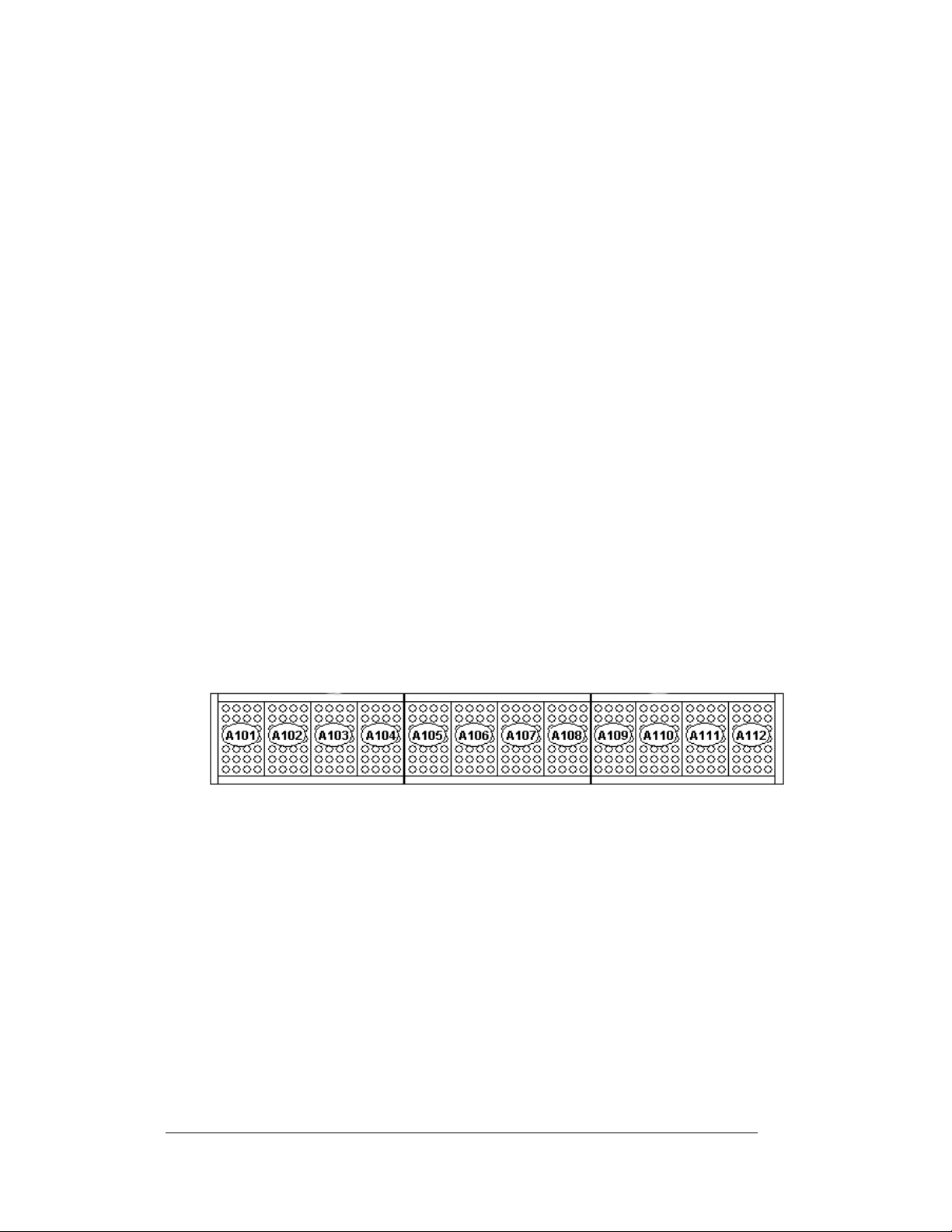
Figure 2: Module Numbering Example 7X48 Front
A module is the building block of the Galaxy display. Each module door for the
133mm/171mm displays measure 7 pixels high by 4 pixels wide. Individual pixels
can be easily removed from the display if required.
Daktronics numbers modules on a Galaxy displa y .
The following labeling formats might be fou nd on va ri o us Daktronics drawings:
• “TB_ _” signifies a termination block for power or signal cable
• “F_ _” represents a fuse
• “E_ _” shows a grounding point
• “J_ _” denotes a power or signal jack
• “P_ _” stands for a power or signal plug for the opposite jack
Figure 2 illustrates how
1-2
Introduction
Finally, Daktronics part numbers are commonly found on drawings. Those part
numbers can be used when requesting replacement parts from Daktronics Customer
Service. Take note of the following part number formats:
• “0P-_ _ _ _-_ _ _ _” indicates an individual circuit board, such as the
internal fiberboard
• “0A-_ _ _ _-_ _ _ _” stands for an assembly, such as a circuit board and the
plate or bracket to which it is mounted
• “W-_ _ _ _” represents a wire or cable
Note: A collection of circuit boards working as a single unit may carry an assembly
label. Cables may also carry the assembly numbering format in certain
circumstances. This is especially true of ribbon cables.
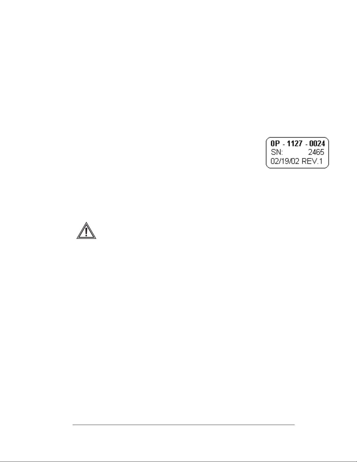
Most circuit boards and components within this display carry a label
that lists the part number of the unit. If a circuit board or assembly is
not listed in the Replacement Parts List in Section 4, use the label to
order a replacement. A typical label is shown in Figure 3. The part
number is in bold
1.2 Safety Precautions
Important Safeguards:
1. Read and understand these instructions before installing
2. Be sure the display and external signal enclosures are properly grounded
with an earth ground electrode at the display
3. Disconnect power when servicing the display
4. Do not modify the display structure or attach any panels or coverings to the
display without the written consent of Daktronics, Inc
Note: This equipment has been tested and found to comply with the limits for a
Class A digital device, pursuant to part 15 of the FCC Rules. These limits are
designed to provide reasonable protection against harmful interference when the
equipment is operated in a commercial environment. This equipment generates, uses,
and can radiate radio frequency energy and, if not installed and used in accordance
with the instruction manual, may cause harmful interference to radio
communications. Operation of this equipment in a residential area is likely to cause
harmful interference. In such cases, the user will be required to correct the
interference at their own expense.
Modifications not expressly approved by the manufacturer could void the user's
authority to operate the equipment under FCC rules.
Figure 3: Typical Label
Introduction
1-3

1.3 Network Concepts
The concept of using LED displays as a cost effective, high impact method of
communication is rapidly growing throughout many industries and businesses. The
reasons for this growth are many, but the need for additional features and the
complexity of multiple display installations has emerged. Daktronics display systems
have been designed to meet those needs.
The common thread to most client requests is a means of programming and
co
ntrolling a group of displays from a central control point. Daktronics responded by
developing a powerful system of interconnecting and controlling displays.
Daktronics has taken great care to design products that will satisfy a wide variety of
installations. Some of the design goals of these systems include the following:
• Easy transfer of messages
• The ability to tell a display or group of displays in the network which
message should run
• The ability to determine the status of any display on the network
• The ability to control multiple display technologies on the same network
There are seven communication methods available: RS232, RS422, Fiber, Ethernet,
Fi
ber Ethernet, Modem and Radio. They differ on the type of physical connections
needed, the distance allowed, and equipment required. A separate manual is
provided for the type of communication method ordered with your display. See
Section 3.7 for the communication manual ED numbers.
Up to 240 displays can exist on one network.
1.4 Display Overview
1-4
Reference Drawing:
Shop Drawings.........................................................Ref
er to Appendix A
Daktronics 133mm/171mm, AF-3400 Galaxy
®
displays are designed and
manufactured for performance, reliability, easy maintenance, and long life. The
pixels have either a 133mm center-to-center spaci n g or a 171m m center-to-center
spacing, and are lit using LEDs (light emitting diodes). A light sensor on the front of
the display is used for automatic dimming of the LEDs based on the ambient light
levels. The configuration of pixels depends on the model of display ordered.
Refer to the appropriate Sh
op Drawing for the approximate size, weight, and power
requirements for your model of display.
Introduction
The Galaxy
®
model numbers are described as follows:
AF-3400-RR-CC-MMM-X
AF-3400 =
RR =
CC =
MMM =
X =
Outdoor Louvered Galaxy Display
Number of Rows High (7)
Number of Columns Long (48, 64, 80)
Pixel to pixel spacing. (133mm or 171mm)
LED Color, (Red or Amber)
A typical display system has a Windows
®
Venus
Windows
an IBM
1500 software. Venus® 1500 is a software package that runs under
®
98, ME™, NT® 4.0, 2000, or XP Home/Professional operati n g sy st ems on
®
-compatible computer.
®
based personal computer (PC) running
The displays are offered as single-face units, which are single-sided, stand alone
displays. The 133mm/171mm displays are front accessible because the internal
components of the display can only be reached by opening module doors.
1.5 Component Identification
The following illustrations depict some of the more commonly accessed Galaxy®
display components. Because Daktronics occasionally alters standard design to meet
customer needs, the actual display design may vary slightly from the illustrations
below.
This is only a brief overview. Refer to Section 4: for additional information on
maintaining the various display components. Additional definitions are given in the
communication manual provided with your display.
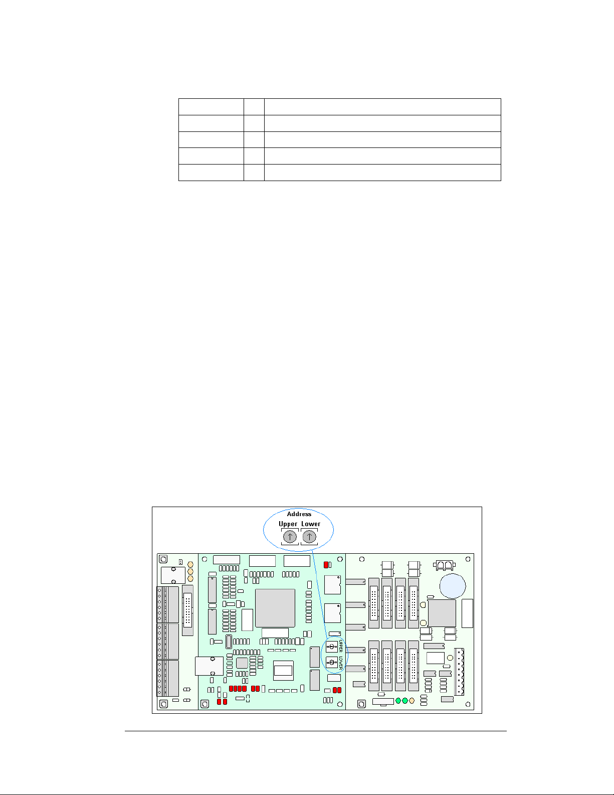
Controller: The display’s controller is the “brains” of the display (refer to Figure
4). The controller receives, translates, and activates the signal information from the
computer to the appropriate pixels on the display.
Figure 4: Version 3 Controller
Introduction
1-5

Display Address: The display address is an identification number assigned to each
display of a network. Rotating the address switches on the controller sets the address
identification number for the display. The control software uses the address to locate
and communicate with the display.
Driver Board: This driver board is also responsible for
the switching and intensity levels of the LEDs. Refer to
Figure 5.
Galaxy
®
: Daktronics trademarked name for LED
monochrome, tri-colored, or RGB matrix displays.
LED (light emitting diode): This is a low energy, high
intensity lighting unit.
Louver: Black metal shade positioned horizontally
above each pixel row. The louvers increase the level of
Figure 5: Driver Board
contrast on the display face and direct LED light.
Module: The modules for the 133mm/171mm Galaxy
®
displays are 4 pixels wide
by 7 pixels high. Because of their large size they are more appropriately called
“module doors”. The module doors have hinges on the left edge, and can be opened
up, much like a door, to access internal components.
Pixel: A pixel is a single LED or cluster of LEDs. The number and color of the
LEDs depends on display application.
Power Supply: Converts AC line voltage from the load center to low DC voltage for
multiple module driver boards
.
1-6
Introduction
Section 2: Mechanical Installation
Note: Daktronics does not guarantee the warranty in situations where the display is not
constantly in a stable environment.
The Daktronics engineering staff must approve any changes that may affect the weathertightness of the display. If any modifications are made, detailed drawings of the changes must
be submitted to Daktronics for evaluation and approval, or the warranty may be void.
Daktronics is not responsible for installations or the structural integrity of support
structures done by others. It is the customer’s responsibility to ensure that a qualified
structural engineer approves the structure and any additional hardware.
2.1 Mechanical Installation Overview
Because every installation site is unique, there is no single Daktronics-approved
procedure for mounting the Galaxy
section is general information only and may or may not be appropriate for your
particular installation.
A qualified individual must make all decisions regarding the mounting of this
display.
Read both the mechanical and electrical installation sections of this manual
before beginning any installation procedures.
®
2.2 Accessing the Display
The Daktronics Galaxy
133mm/171mm AF-3400 large
character displays are front accessible;
meaning, access to the internal
components can only be gained from
the front of the display. The module
doors are approximately
20 ½”X41 ½” for the 133mm and
26 ½”X53 ½” for the 171mm and are
7 pixels high by 4 pixels wide. Follow
these steps to open a module door and
access the internal components.
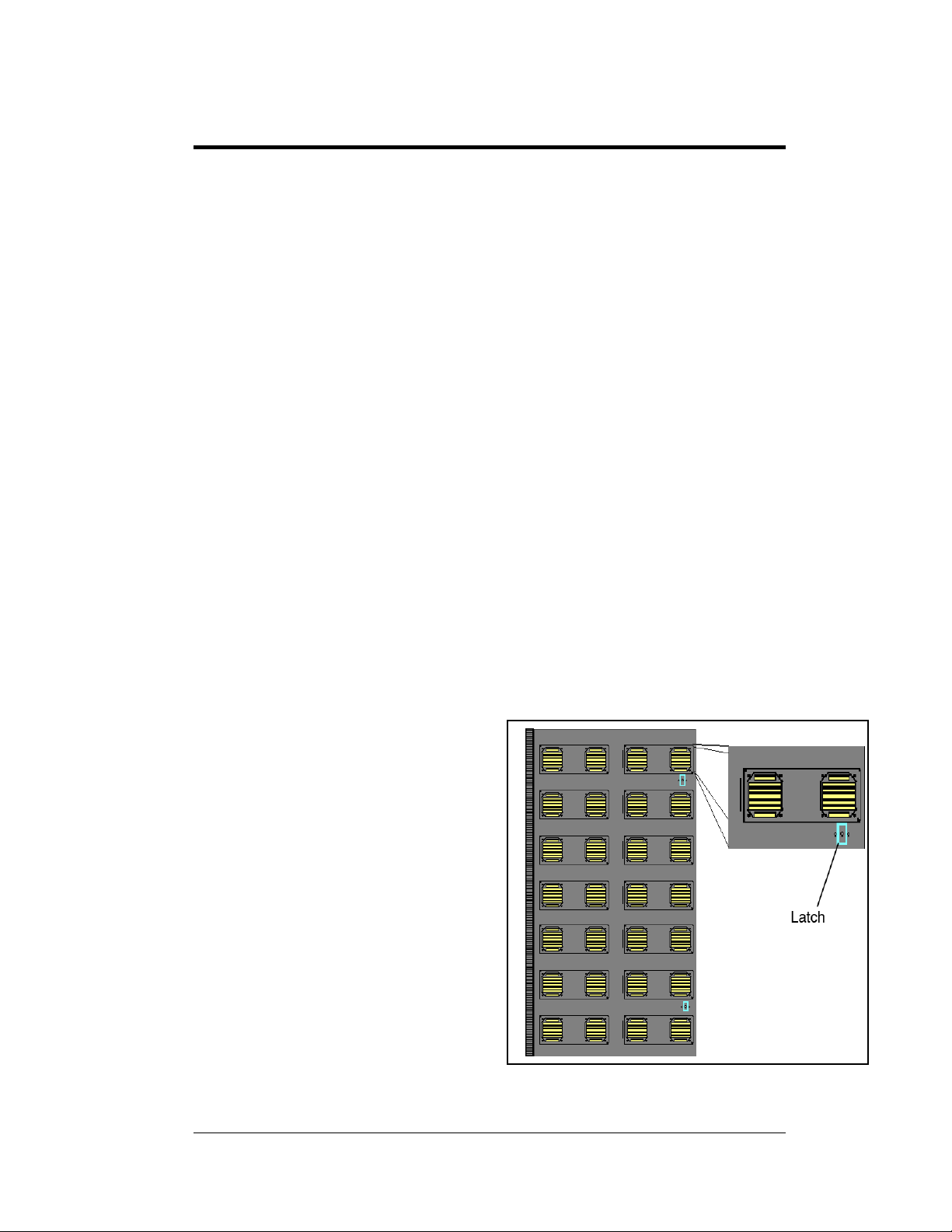
1. Locate the latch access
fasteners on the module.
Refer to Figure 6 for latch
access fastener locations.
2. With a Phillips head
screwdriver, turn the latch
access fasteners clockwise as
shown in Figure 7
Mechanical Installation
displays. The information contained in this
Figure 6: Latch Fastener Locations on Module Door
2-1

3. Gently pull the module door forward.
4. Gently open the door. The wires
connected to the module door provide
enough slack to open the module door,
however, if you want to remove the door
you will have to disconnect the wires.
2.3 Support Structure Design
Figure 7: Opening the Module Door
Support structure design depends on the mounting methods, display size, and weight.
The structure design is critical and should be done only by a qualified individual.
Display height and wind loading are also critical factors. It is the customer’s
responsibility to ensure that the structure and mounting hardware are adequate.
Daktronics is not responsible for the installations or the structural inte gri t y of
support structures done by others.
It is the installer’s responsibility to ensure the mounting structure and
hardware are capable of supporting the display and will agree with local codes.
Before beginning the installation proces s, verify the following:
• All clip angles or mounting holes must be attached to the support structure
• The mounting structure will provide a straight and square-mounting frame
for the display
• The mounting structure is capable of supporting the display and will not
yield at any unsupported points after mounting
• Make sure that 3" of unobstructed space is available above the top of the
display to remove the eyebolt.
Note: No clearance is required once the eyebolt is removed. Correct any deficiencies
before installation.
2-2
Mechanical Installation

2.4 Ventilation Requirements
Reference Drawing:
Shop Drawings........................................................................Appendix A
Fans are mounted to the back sheet for ventilation. Cool air is brought in through the
bottom half of the sign and then the fans in the back exhaust hot air. Refer to
and the appropriate Shop Drawing for fan locations.
If the display cabinet is completely enclosed:
• 6 square inches of unobstructed
opening must exist around the bottom
and back of the display.
• Allowances must be made to
compensate for the percentage of
material covering the openings in the
structure.
• For adequate cooling, forced
ventilation may be required. If air is
forced into the enclosed cabinet, 10
cubic feet per minute must be
provided per module (10.64" x
10.64" active area).
If these requirements are not met, the Galaxy
Figure 8: Fan on Inside of Backsheet
®
display warranty may be void.
Figure 8
2.5 Lifting the Display
The top of the display is equipped with eyebolts that are used to lift the unit. Take
special care to ensure that the rated load of the eyebolts is not exceeded. Refer to the
information at the end of this section labeled Eyebolts to determine the allowable
load of the eyebolts shipped with the display.
Figure 9 illustrates both the correct (left example) and the incorrect (right example)
method of lifting a display. Lift the display as shown on the left, with the lifting bar.
Use every lifting point provided.
Do not attempt to permanently support the display by the eyebolts.
Eyebolts can be removed
from the display to
eliminate the need for
overhead clearance.
Figure 9: Lifting the Display (Correct, Left; Incorrect, Right)
Mechanical Installation
2-3

2.6 Display Mounting
Reference Drawing:
Shop Drawings
The method used to mount displays can vary greatly from location to location. For
th
is reason, only general mounting topics can be addressed in this manual.
It is the responsibility of the installer to
meet local codes and standards, as well as the mounting hardware and method.
Before beginning the installation proces s, verify the following items:
• The mounting structure will provide a straight and square-mounting frame
for the display – height variation in any four-foot horizontal section may
not exceed ¼-inch
• The mounting structure will not give way at any unsupported points after
the display is mounted
The back of the display is equipped with 3 x 3
shown in the Shop Drawing for your display size. These angles may be used for
mounting purposes. Remember to have all mounted displays inspected by a qualified
structural engineer.
Refer to the appropriate Sh
number of attachment points needed and the wall structure must be reviewed by a
qualified structural engineer and meet all national and local codes. It is the
customer’s responsibility to determine the proper wall mounting method and
location. Daktronics requires using all clip angles or mounting holes as attachment
points.
1. C
possible damage that may have occurred during shipping
2. R
required.
3. Fol
position on the support structure. Secure the display to the support structure
with mounting clips.
4. A
5. Bo
clip angles to the support structure as shown in the Shop Drawings. Refer
to Section 3 for information on routing power to the display, and your
communication manual for routing the signal.
6. After in
that may allow water to seep into the display and seal any openings with
silicone – if the eyebolts on the top of the display have been removed,
plug the holes with bolts and the rubber-sealing washer that was
removed with the eyebolt (unless there is an overhead structure)
.............................................................................. Appendix A
op Drawings for a suggested wall mount m e t ho d. The
arefully uncrate the display and inspect each side of the display for
emove the backsheet assemblies from the sections to be installed as
lowing the guidelines described in Section 2.4, lift the display into
lign the sections by using through holes as required.
lt sections together using ½" Grade-5 bolts and hardware to secure the
stallation is complete, carefully inspect the display for any holes
ensure the installation will adequately
x 3/8" steel clip angles at the locations
2-4
Mechanical Installation

2.7 Optional Temperature Sensor Mounting
If an optional temperature sensor will be used with this display, see Appendix B for
mounting and signal connections.
Mechanical Installation
2-5

 Loading...