

Page 1

Galaxy AF-3400 12 mm
Display Manual
ED-17998 Rev 1 23 March 2009
Website: www.daktronics.com
Tel 866-343-3122 Fax: 605-697-4444
331 32nd Ave PO Box 5128 Brookings SD 57006
Page 2
ED-17998
Product 1260
Rev 1–23 March 2009
DAKTRONICS, INC.
Copyright 2009
All rights reserved. While every precaution has been taken in the preparation of this manual,
the publisher assumes no responsibility for errors or omissions. No part of this book covered
by the copyrights hereon may be reproduced or copied in any form or by any means – graphic,
electronic, or mechanical, including photocopying, taping, or information storage and retrieval
systems – without written permission of the publisher.
®
is a registered trademark of Daktronics, Inc. All others are trademarks of their respective companies.
Galaxy
Page 3

Table of Contents
Section 1: Introduction ................................................................................................................. 1
1.1 Safety Precautions ................................................................................................................... 1
1.2 Display Overview ................................................................................................................... 1
Section 2: Mechanical Installation .............................................................................................. 3
2.1 Support Structure Requirements .......................................................................................... 3
Pre-installation Checklist ................................................................................................ 4
2.2 Lifting the Display .................................................................................................................. 4
2.3 Display Mounting ................................................................................................................... 5
2.4 Temperature Sensor Mounting ............................................................................................. 5
Section 3: Power Installation ....................................................................................................... 7
3.1 Preparing for Power Connection .......................................................................................... 7
3.2 Conduit ..................................................................................................................................... 7
3.3 Power Requirements .............................................................................................................. 8
Main Disconnect .............................................................................................................. 8
Grounding......................................................................................................................... 8
Power Connection ............................................................................................................ 9
Section 4: Signal Overview ........................................................................................................ 15
4.1 Primary to Primary Signal Connection .............................................................................. 15
4.2 RS-422 Communication ........................................................................................................ 17
4.3 Fiber Optic Communication ................................................................................................ 18
4.4 Radio Communication ......................................................................................................... 19
4.5 RS-232 Communication ........................................................................................................ 20
4.6 Ethernet Communication ..................................................................................................... 21
4.7 Fiber Ethernet Communication ........................................................................................... 22
4.8 Ethernet Bridge Radio Communication ............................................................................. 23
4.9 Modem Communication ...................................................................................................... 24
4.10 Temperature Sensor Installation ......................................................................................... 25
Section 5: Start-up Procedure ................................................................................................... 27
5.1 Start-up Checklist .................................................................................................................. 27
5.2 Start-up Sequence ................................................................................................................. 28
Section 6: Maintenance and Parts Replacement ..................................................................... 29
6.1 Display Access ....................................................................................................................... 30
6.2 Maintenance ........................................................................................................................... 31
Ventilation ...................................................................................................................... 31
Thermostats .................................................................................................................... 31
Weather Stripping .......................................................................................................... 31
Annual Maintenance ..................................................................................................... 32
Table of Contents i
Page 4

6.3 Troubleshooting .................................................................................................................... 32
6.4 Replacement Parts List ......................................................................................................... 33
6.5 Replacing Parts ...................................................................................................................... 35
Location of Internal Components ................................................................................ 35
Module Replacement ..................................................................................................... 35
Transformer and RFI Filter Replacement ................................................................... 36
Power Supply Replacement .......................................................................................... 36
Section 7: Daktronics Exchange and Repair & Return Programs .......................................... 41
Before Contacting Daktronics ...................................................................................... 41
7.1 Exchange Program ................................................................................................................ 41
7.2 Repair & Return Program .................................................................................................... 42
7.3 Daktronics Warranty and Limitation of Liability ............................................................. 42
Appendix A: Reference Dra wings.................................................................................................. 43
Appendix B: Temperature Sensor ................................................................................................. 44
Appendix C: Daktronics Warranty and Limitation of Liability (SL-02374) ................................. 45
Table of Content ii
Page 5

List of Figures
Figure 1: Drawing Label ........................................................................................................................ 1
Figure 2: Galaxy 12 mm 24 x 112 .......................................................................................................... 2
Figure 3: Back View of Typical Display .................................................................................................. 3
Figure 4: Lifting the Display .................................................................................................................... 4
Figure 5: Proper Grounding .................................................................................................................... 9
Figure 6: 120 VAC Power Termination ................................................................................................. 10
Figure 7: 120/240 VAC Power Termination .......................................................................................... 10
Figure 8: Making Cage Clamp Connections ......................................................................................... 11
Figure 9: One-circuit 120 VAC Termination One-circuit 240 VAC Termination .............................. 12
Figure 10: Two-circuit 120/240 VAC Termination ................................................................................ 12
Figure 11: RS-422 Interconnection from Primary to Primary Display .................................................. 16
Figure 12: RS-422 Communication Layout .......................................................................................... 17
Figure 13: Fiber Serial Communication Layout .................................................................................... 18
Figure 14: Radio Communication Layout ............................................................................................. 19
Figure 15: RS-232 Communication Layout .......................................................................................... 20
Figure 16: Ethernet Communication Layout ......................................................................................... 21
Figure 17: Fiber Ethernet Communication Layout ................................................................................ 22
Figure 18: Ethernet Bridge Radio Layout ............................................................................................. 23
Figure 19: Modem Communication Layout .......................................................................................... 24
Figure 20: Basic Display Set-up ........................................................................................................... 27
Figure 21: Location of Internal Components ........................................................................................ 29
Figure 22: Opening Display .................................................................................................................. 30
Figure 23: Display fans ......................................................................................................................... 31
Figure 24: Typical Label ....................................................................................................................... 33
Figure 25: Removing a Module ............................................................................................................ 35
Figure 26: One-circuit Power Termination ............................................................................................ 36
Figure 27: Power Supply ...................................................................................................................... 36
Figure 28: Controller Component Layout ............................................................................................. 38
List of Figures iii
Page 6

Page 7
Section 1: Introduction
This manual explains the installation, maintenance, and troubleshooting for the Galaxy AF-3400
12 mm display. For questions regarding the safety, installation, operation, or service of this system,
please refer to the telephone numbers listed on the cover page of this manual.
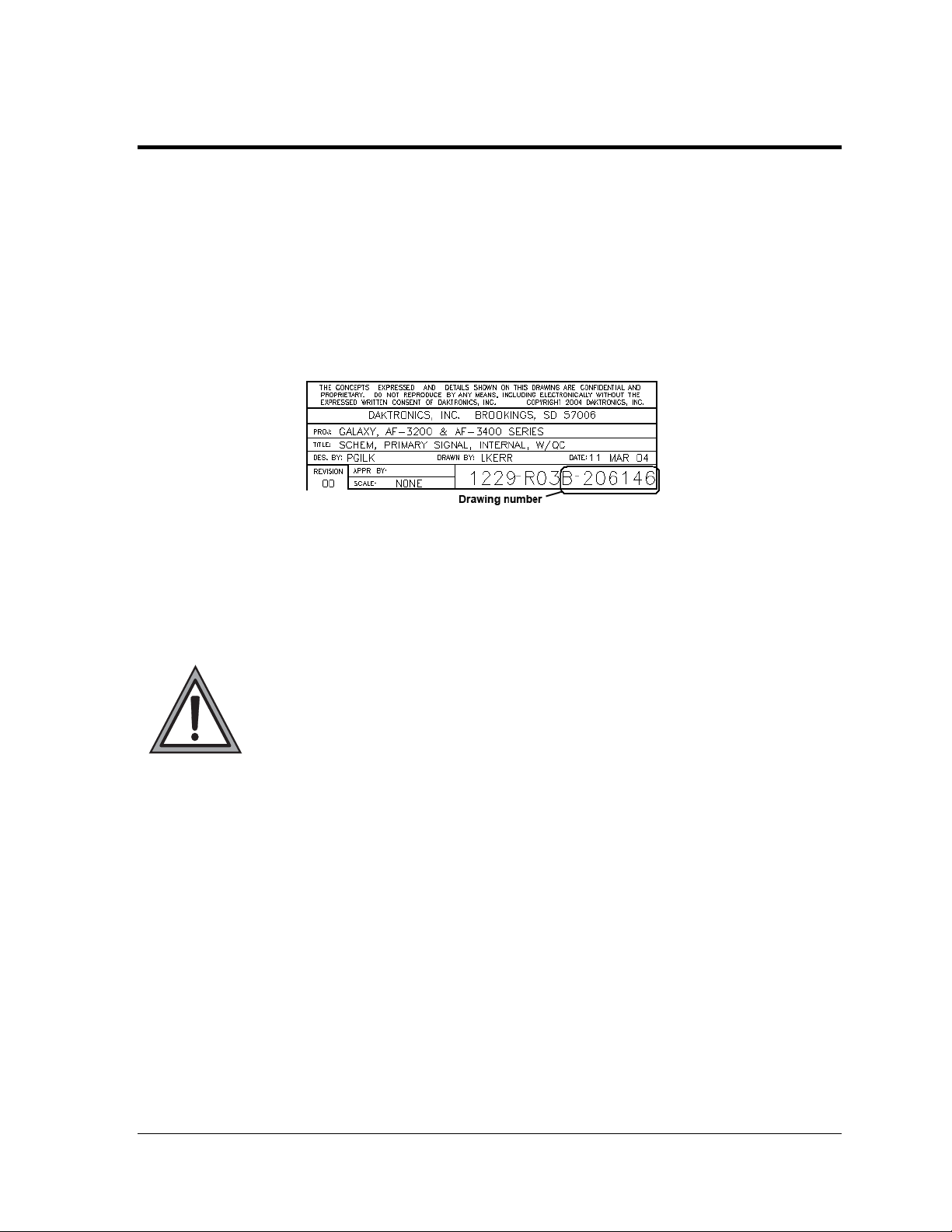
Drawings may be referenced by drawing number at the beginning of some sections. Figure 1
illustrates the Daktronics drawing label. The drawing number is located in the lower-right corner of
the drawing. The drawing number consists of the last set of digits and the letter preceding them. In
the example below, the drawing would be referred to as Drawing B-206146. Reference drawings are
inserted in Appendix A.
Figure 1: Drawing Label
1.1 Safety Precautions
Important Safeguards:
Read and understand these instructions before installing
Be sure the display and external signal enclosures are properly grounded with
an earth ground electrode at the display
Disconnect power when servicing the display
Do not modify the display structure or attach any panels or coverings to the
display without the written consent of Daktronics.
1.2 Display Overview
The Galaxy® AF-3400 12 mm displays are designed and manufactured for performance,
reliability, easy maintenance, and long life. The pixels have a 12 mm center-to-center spacing
and are lit using LEDs (light-emitting diodes). A light sensor on the front of the display is
used for automatic dimming of the LEDs based on the ambient light levels.
The Galaxy
®
display number for these displays is described as follows:
Introduction 1
Page 8
AF-3400-RxC-12-RGB
AF-3400 =
R=
C=
12 =
RGB =
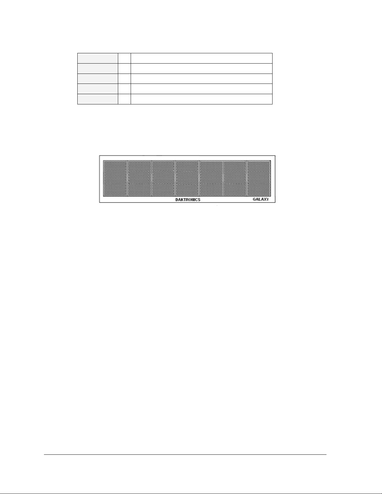
A module is the building block of the Galaxy
by 16 pixels wide. By placing modules next to each other, a display of any size can be
designed and built. Individual modules can be easily removed from the display if required.
Figure 2 shows a typical Galaxy
Figure 2: Galaxy 12 mm 24 x 112
Outdoor louvered Galaxy display
Number of rows high
Number of columns long
12 mm pixel to pixel spacing
LED color (Red, Green, and Blue)
®
display. Each module measures 24 pixels high
®
12mm display.
Introduction 2
Page 9
Section 2: Mechanical Installation
Da ktronics engineering staff must approve any changes to the display. If any
modifications are made, detailed drawings of the changes must be submitted to
Daktronics for evaluation and approval, or the warranty may be void.
Daktronics is not responsible for installations or the structural integrity of
support structures done by others. The customer is responsi ble for ensuring
that a qualified structural engineer approves the structure and any hardware.
2.1 Support Structure Requirements
Because every installation site is unique, no single procedure is approved by Daktronics for
mounting Galaxy
only and may or may not be appropriate for this particular installation.
A qualified individual must make all decisions regarding the mounting of this display.
Support structure design depends on the mounting methods, display size, and weight. In
general, the front of the display needs to be unobstructed to allow for air flow and internal
access. The bottom of the display houses the fans so allowances will need to be made for their
operation. Also keep in mind the location of the mounting clips and the power/signal
termination box or knockouts on the back of the display. Display height and wind loading
are also critical factors to be considered. This information can be found in the Shop drawing
provided with the display.
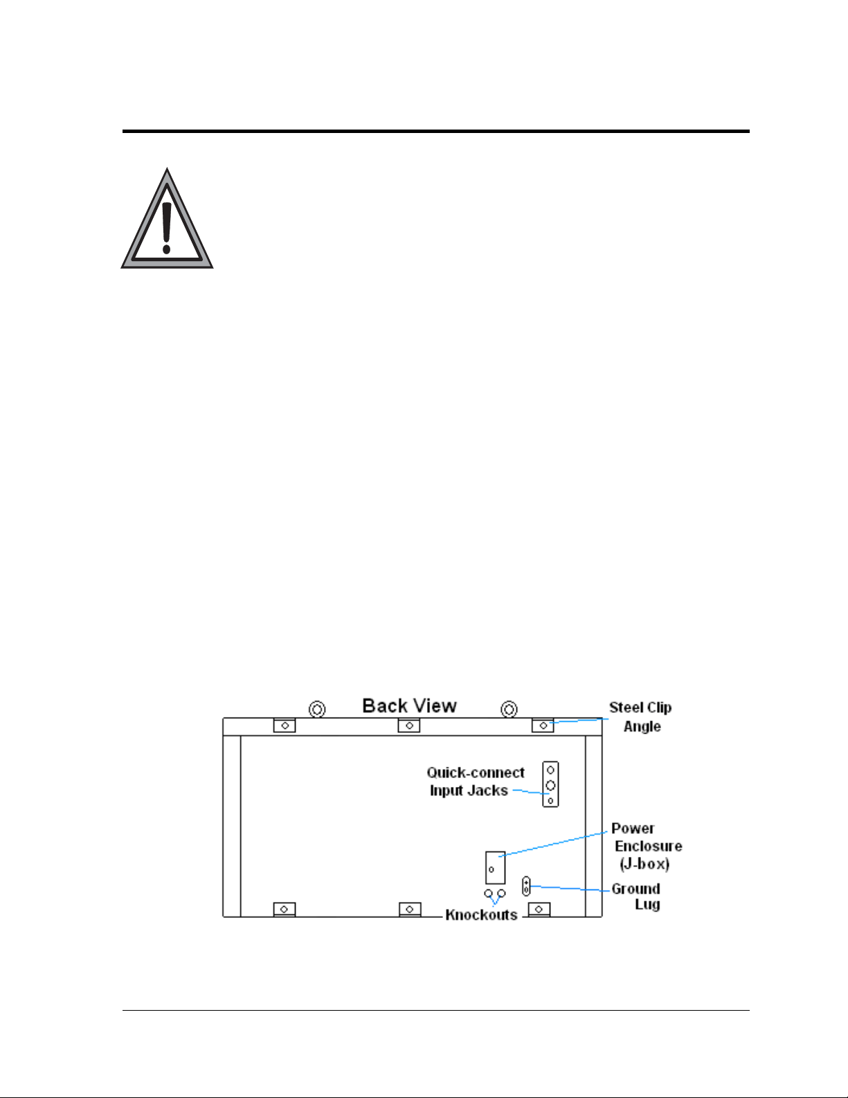
The external components and their typical location are shown in Figure 3. Refer to the
specific shop drawing for the actual dimensions and location of components in a particular
display.
®
displays. The information contained in this section is general information
Figure 3: Back View of Typical Display
Mechanical Installation 3
Page 10
Pre-installation Checklist
Verify the following before proceeding with installation:
The display is in good condition after shipping and uncrating.
All clip angles or mounting holes are attached to the support structure.
A straight and square mounting frame is provided for the display.
Height variation in any four-foot horizontal section may not exceed ¼-inch.
Adequate support is provided for the display so that the structure will not yield at
any unsupported points after mounting.
Clearance of 4" of unobstructed space above the top of the display is allowed to
remove the eyebolt. Note: No clearance is required once the eyebolt is removed.
Clearance in front of the display is maintained to allow unobstructed air flow
through the vents and to allow access to internal components.
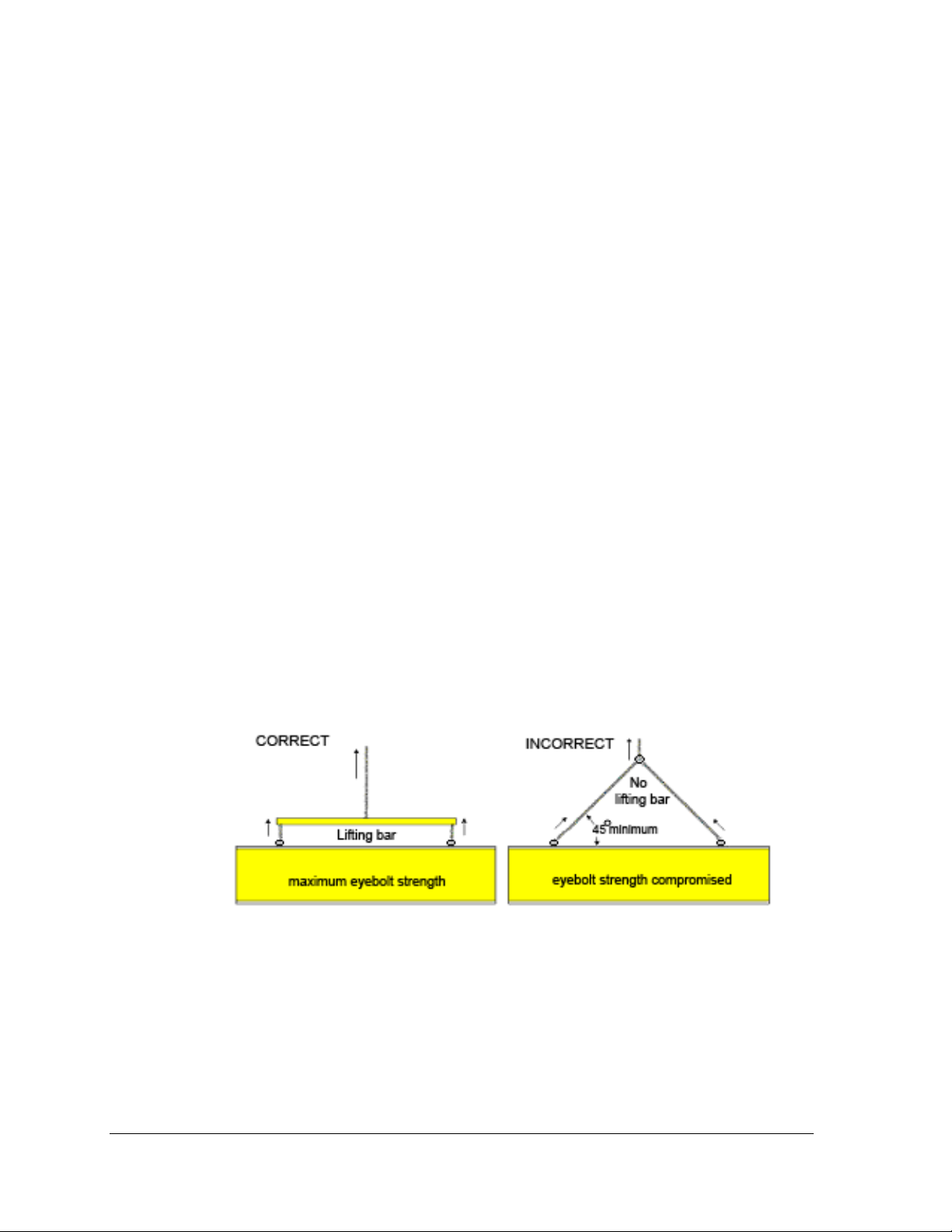
2.2 Lifting the Display
The top of the display is equipped with eyebolts that are used to lift the unit. Take special
care to ensure that the rated load of the eyebolts is not exceeded. Refer to the information at
the end of this section labeled Eyebolts to determine the allowable load of the eyebolts
shipped with the display.
Figure 4 illustrates both the correct (left example) and the incorrect (right example) method
of lifting a display. Lift the display as shown on the left, with the lifting bar. Use every lifting
point provided.
Figure 4: Lifting the Display
Do not attempt to permanently support the display by the eyebolts.
Eyebolts can be removed after mounting to eliminate the need for overheard clearance.
Mechanical Installation 4
Page 11

2.3 Display Mounting
The method used to mount displays can vary greatly from location to location. For this
reason, only general mounting topics can be addressed in this manual.
The back of the display is equipped with 2" x 2" x 1/4" x 3" steel angles at the top and bottom
as shown in Figure 3. All angles must be used for display installation. Remember to have
all mounted displays inspected by a qualified structural engineer.
The number of attachment points needed and the mounting structure must be reviewed by a
qualified structural engineer and meet all national and local codes. It is the customer’s
responsibility to determine the proper wall mounting method and location. Daktronics
requires using bottom mounting angles or all mounting holes as attachment points.
1. Carefully uncrate the display and inspect each side of the display for possible
damage that may have occurred during shipping.
2. Following the guidelines described in Section 2.2 lift the display into position on the
support structure.
3. Weld or use ½" Grade-5 bolts and hardware to secure the mounting angles to the
support structure as shown in the Shop Drawing.
4. Refer to Section 3 for information on routing power to the display.
5. After installation is complete, carefully inspect the display for any holes that may
allow water to seep into the display and seal any openings with silicone. If the
eyebolts on the top of the display have been removed, plug the holes with bolts
and the rubber-sealing washer that was removed with the eyebolt (unless
prevented by an overhead structure).
2.4 Temperature Sensor Mounting
Refer to Appendix B for instructions on mounting and connecting signal for the temperature
sensor.
Mechanical Installation 5
Page 12

Page 13
Section 3: Power Installation
Only a qualified individual should terminate power and signal cable at this
Daktronics display.
The Daktronics engineering staff must approve any changes made to the display.
Before altering the display, submit detailed drawings for the proposed modifications
to the Daktronics engineering staff for evaluation and approval or the warranty will
be rendered null and void.
Schematic, Power Term Panel, 2 Circuit-120/240VAC ............................................. Drawing A-211947
Schematic, Power Term Panel, 1 Circuit-120VAC .................................................... Drawing A-211950
Schematic, Power Term Panel, 2 Pole-240VAC ....................................................... Drawing A-218666
Schematic, Power Term Panel, 1 Pole-240VAC ....................................................... Drawing A-220287
Schematic, AF-3400-12-RGB-P, General ................................................................. Drawing A-253685
Power Specs, AF-3400-(24x192-96-192-12-RGB ..................................................... Drawing A-254277
3.1 Preparing for Power Connection
A power termination box is provided on the back of the display. If the installation of the
display does not allow for the use of this enclosure, refer to Section 3.6 for information
on the internal wiring for the power.
Route power to the display through a fused disconnect switch capable of opening all
ungrounded power conductors. Install this disconnect within the line-of-sight of any
personnel performing maintenance on the display. If the disconnect is located out of
sight of the display, it must be capable of being locked in the open position.
Note: Displays are equipped with supplemental protection devices that carry a UL1077
(IEC 60947, VDE 660) rating. These devices are only intended to protect the components
within the display. Suitable devices must be used for the equipment and feeders
supplying power to the display.
Power conductors from the disconnect to the display should be routed through conduit
in agreement with local code.
Display power will terminate to the display at the external power termination J-box
mounted to the back of the display.
Connect the grounding electrode conductor at the grounding lug on the display at this
time.
3.2 Conduit
Daktronics does not include the conduit. Separate conduit must be used to route:
Power
Signal IN wires to the display, when applicable
Electrical Installation 7
Page 14
The power J-box on the back of the display is provided with ¾” threaded holes for use with
¾” conduit. If necessary, knockout/drill holes are provided in the display cabinet itself when
not using the enclosure.
3.3 Power Requirements
Each display uses one 120 VAC or 120/240 VAC single phase power source. Proper power
installation is imperative for proper display operation. Refer to Drawing A-254277 for power
specifications for the specific display size.
Main Disconnect
The National Electrical Code requires the use of a lockable power disconnect near the
display. Provide a lockable disconnect switch (knife switch) at the display location so that all
power lines can be completely disconnected. Use a 3-conductor disconnect so that both hot
lines and the neutral can be disconnected. The main disconnect should be mounted at or near
the point of power supply connection to the display. A main disconnect is to be provided for
each supply circuit to the display.
The disconnecting means must be located in a direct line-of-sight from the display or outline
lighting that it controls. This requirement provides protection by enabling a worker to keep
the disconnecting means within view while working on the display.
Exception: Disconnecting means that are capable of being locked in the open position may be
located elsewhere.
Grounding
This sign is to be installed in accordance with the requirements of Article 600 of the National
Electrical Code and/or other applicable local codes. This includes proper gr ounding and
bonding of the sign.
For these displays, installation with ground and neutral conductors provided is used. The
power cable must contain an isolated earth-ground conductor. Refer to Figure 5 for the an
overview of proper grounding.
Under this circumstance, do not connect neutral to ground at the disconnect or at the display.
This would violate electrical codes and void the warranty. Use a disconnect so that all hot
lines and neutral can be disconnected. The National Electrical Code requires the use of a
lockable disconnect within sight of or at the display.
The display system must be connected to earth-ground. Proper grounding is necessary for
reliable equipment operation. It also protects the equipment from damaging electrical
disturbances and lightning.
The display must be properly grounded, or the warranty will be void.
Electrical Installation 8
Page 15
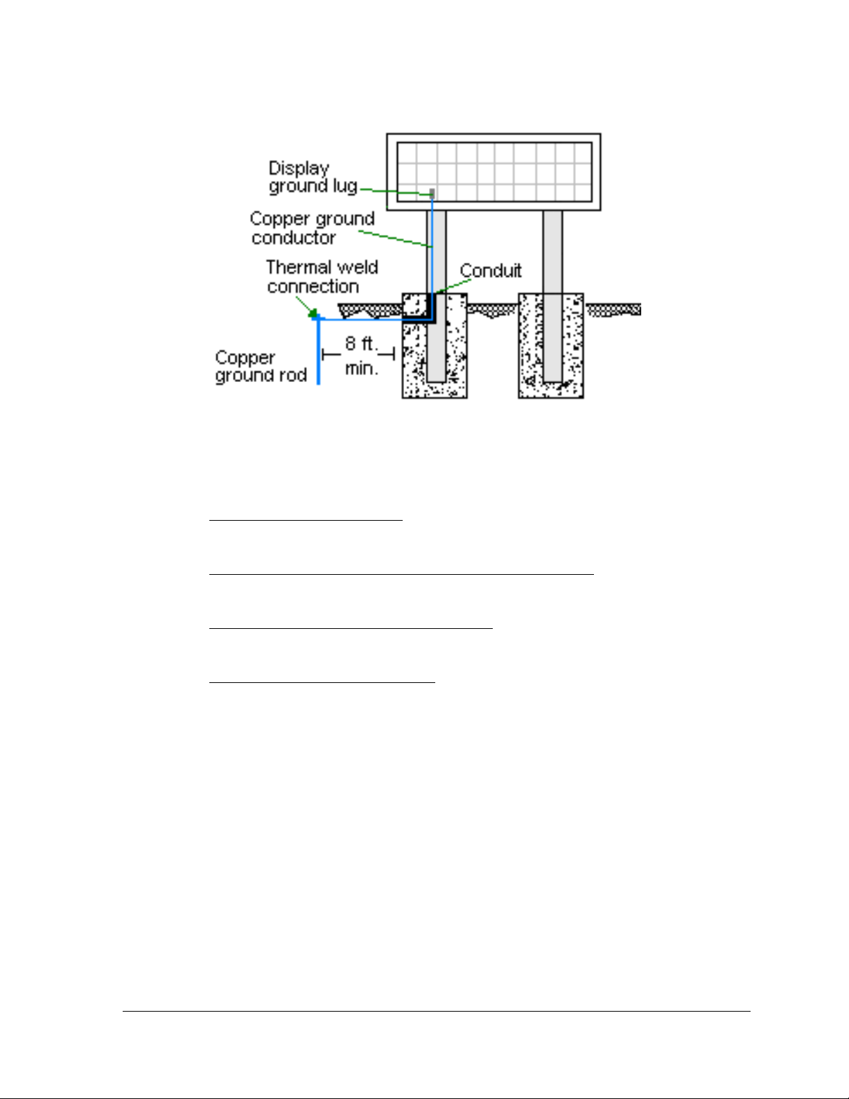
Figure 5: Proper Grounding
Important points about grounding:
Follow local and national codes
region to region and from conditions present at the site. Consult the National Electrical
Code and any local electrical codes that may apply.
Support structure cannot be used as an earth-ground electrode
generally embedded in concrete. If in earth, the steel is either primed or it corrodes,
making it a poor ground.
One grounding electrode for each display face
grounding rod for each display face. Other grounding electrodes as described in Article
250 of the National Electric Code may be used.
Resistance to ground 10 ohms or less
performance. If the resistance to ground is higher than 10 ohms, it will be necessary to
install additional grounding electrodes to reduce the resistance. The grounding
electrode should be installed within 25 feet of the base of the display. The grounding
electrode must be connected to the ground lug on the back of the display (Figure 5).
: The material of an earth-ground electrode differs from
: The support is
: The grounding electrode is typically one
: This is required by Daktronics for proper display
Power Connection
Two options are possible for terminating power to the display:
terminating power to the J-box.
terminating power directly to the power termination panel inside the display.
Installation instructions for both are provided in this section.
Electrical Installation 9
Page 16
Option 1: Terminating hot, neutral, and ground wires at the J-box
Display power is connected to the power termination enclosure on the back of the display.
Complete the following steps to terminate the hot, neutral, and ground wires at the
termination enclosure.
1. Route the power cable through ½” conduit to the rear of the display and into the
power termination enclosure.
2. The power termination enclosure will contain two wires plus a ground coming from
the interior of the display – these wires are pre-terminated to the power termination
panel inside the display.
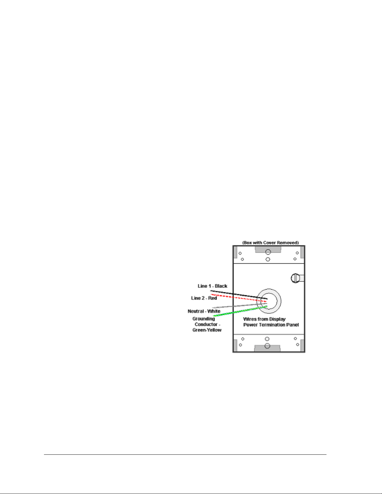
3. Inside the external power termination J-box, connect the power wires to the wires
coming from the display interior, using wire nuts. Refer to Figure 6 for further
information.
Note the following colors are used for the pre-terminated wires:
120 VAC 120/240 VAC
Line 1 – Black x Line 1 - Black
Neutral - White x Line 2 - Red
Grounding Conductor - Green-Yellow x Neutral - White
x Grounding conductor – Green-yellow
Figure 6: 120 VAC Power Termination
Figure 7: 120/240 VAC Power Termination
Electrical Installation 10
Page 17
Option 2: Terminating power through direct connections
If these power terminations cannot be made at the enclosure, they can be made directly to the
power termination panel in the display. The following steps will need to be done to complete
internal connections:
1. Open the display as explained in Section 6.1 and locate the power termination panel.
2. Route the cable through conduit to the back of the display – use one of the ½”
knockouts for access, being careful not to damage any internal components.
3. Disconnect the wires to the terminal block going to the external power J-box, and
connect the wires from the direct cable.
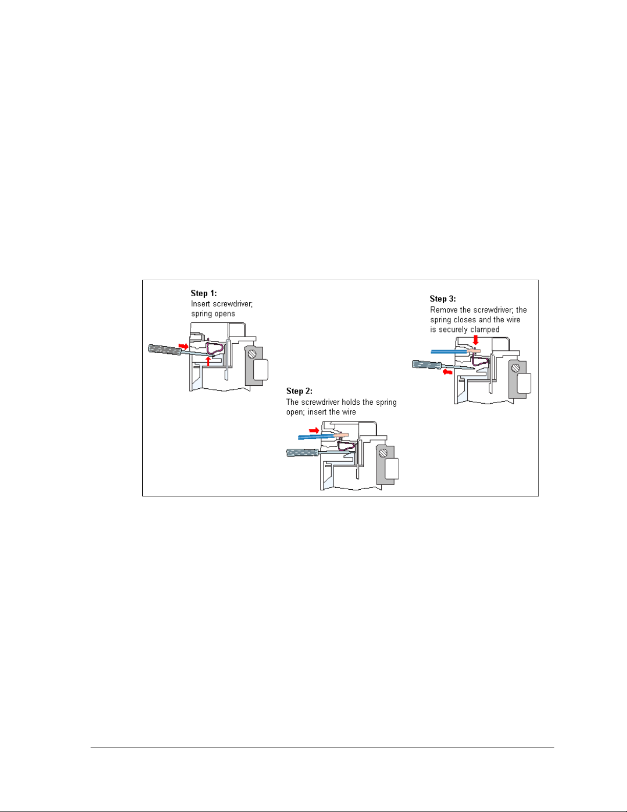
4. Using a small flat screwdriver to open the cage clamps, release the jumper wires
connected to the external wires going to the external power termination box.
5. Install the wires from the direct circuit into the cage clamps following the directions
in Figure 8.
Figure 8: Making Cage Clamp Connections
Electrical Installation 11
Page 18
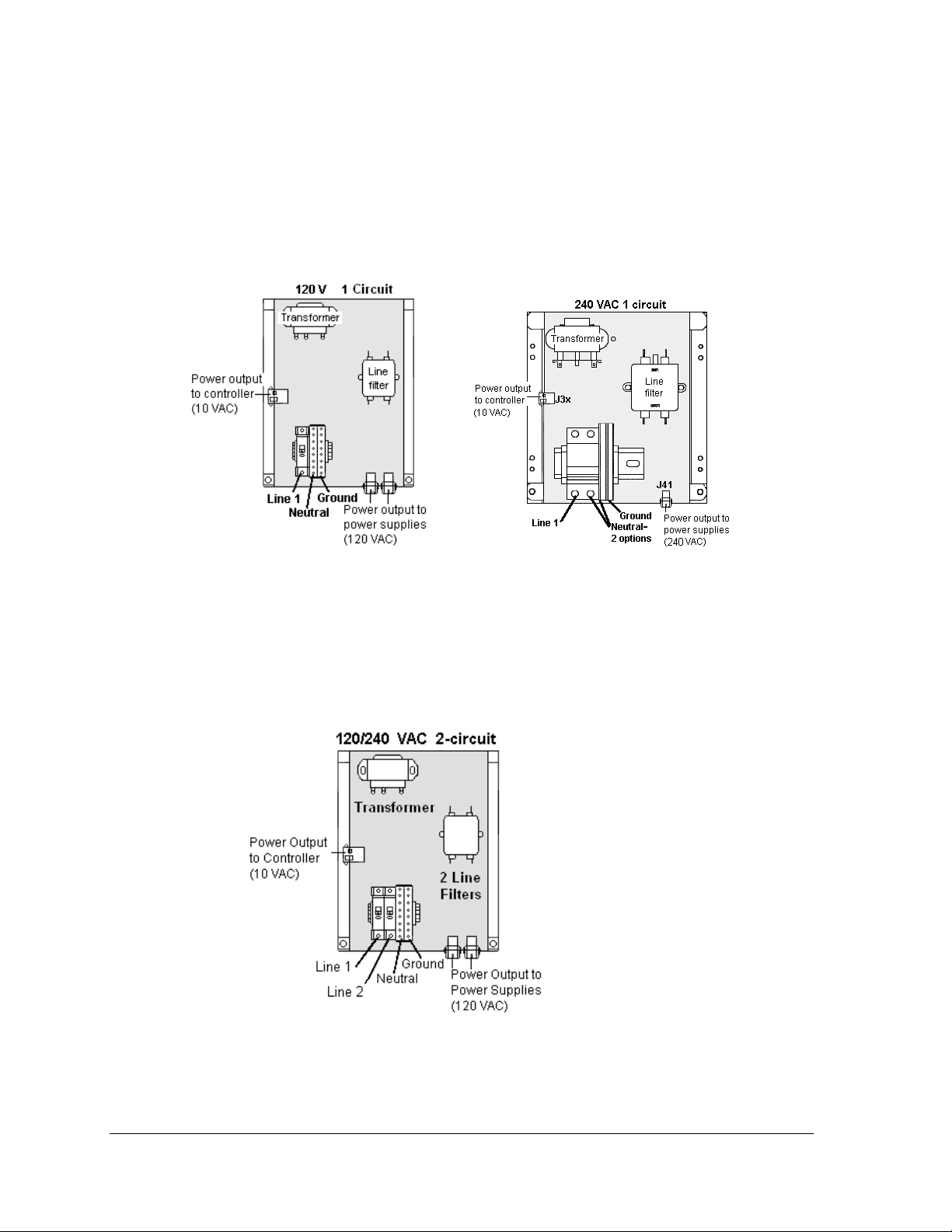
6. Make the following connections as shown in Figure 9
1-circuit termination
Line 1 to circuit breaker 1 (line side)
Neutral to gray terminal block (line side)
Ground to green/green yellow terminal block
:
Figure 9: One-circuit 120 VAC Termination One-circuit 240 VAC Termination
2-circuit termination
Line 1 to circuit breaker 1 (line side)
Line 2 to circuit breaker 2
Neutral to gray terminal block (line side)
Ground to green/green yellow terminal block
Figure 10: Two-circuit 120/240 VAC Termination
Refer to the Schematic Drawings in Appendix A for additional information.
Electrical Installation 12
Page 19

Electrical Installation 13
Page 20

Page 21
Section 4: Signal Overview
Daktronics Galaxy displays are equipped to receive many types of communication signals. The
following sections include a brief description of each available communication type. Also included is
a list of troubleshooting tips to check that the display is connected and configured correctly.
For specific details on installing the signal, consult the quick guide and the manual. These were
included in the shipment of the communications equipment. Each type is listed below with its
manual number.
Note: These are the standard communication types. However, each site is unique and may include
additional equipment. If problems arise, contact the display’s seller, service company, or Daktronics
Customer Service.
Communication
Type
RS-422
Fiber
Radio
RS-232
Ethernet
Fiber Ethernet
Ethernet Radio
Modem
Communication
Manual ED#
ED-14742
ED-14743
ED-13932
ED-14739
ED-14745
ED-14746
ED-16483
ED-14744
4.1 Primary to Primary Signal Connection
If this location requires multiple displays mounted back-to-back, two primary displays will be
installed. In that case, the following connections need to be made:
Remove the module from the bottom left corner of the display and locate the controller
for this display.
Route cable through conduit from the back of the first primary display to the back of the
second primary display. Use the knockouts for access, being careful not to damage any
internal components
Use either a 4-pair signal cable or two 4-conductor, shielded cables to connect both the
signal and the temperature sensor information between displays.
The signal cable will connect from TB3 out on the first primary display to either:
o A surge board at TB1 in a second primary display or
o To TB2 on the controller in the second primary display.
Note: In either case the connections are flipped. Refer to the table following and to Figure 11
for connections on both displays.
Signal Overview 15
Page 22
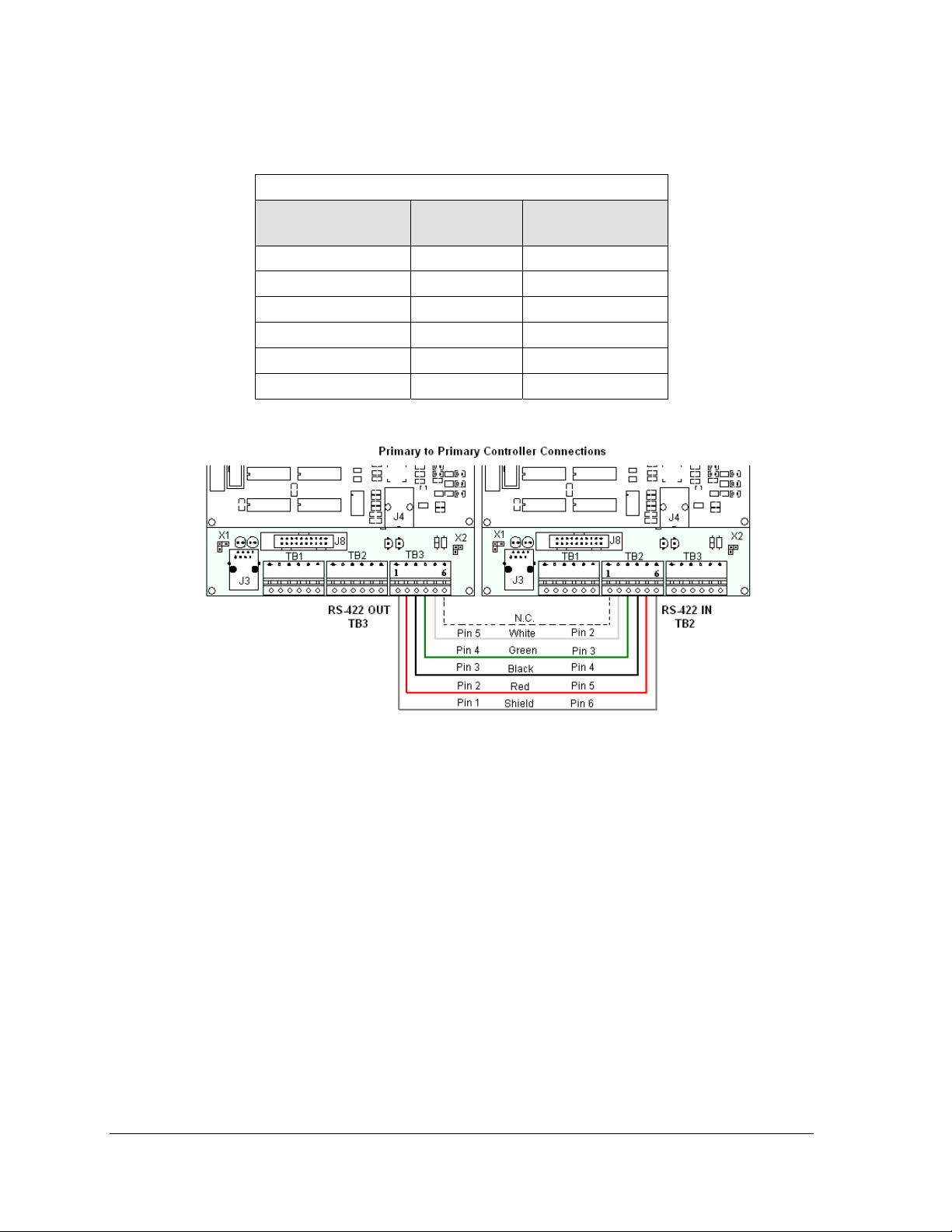
Primary
RS422 OUT (TB3)
Pin 1 (GND) Shield Pin 6 (GND)
Pin 2 (D2OUT-N) Red Pin 5 (D1IN-N)
Pin 3 (D2OUT-P) Black Pin 4 (D1IN-P)
Pin 4 (D2IN-N) Green Pin 3 (D1OUT-N)
Pin 5 (D2IN-P) White Pin 2 (D1OUT-P)
Pin 6 (Shield) Pin 1 (Shield)
RS-422 Interconnection Wiring
Field Cabling Primary
RS422 IN (TB2)
Figure 11: RS-422 Interconnection from Primary to Primary Display
Signal Overview 16
Page 23

4.2 RS-422 Communication
If the communication system is RS-422, look for:
a signal converter near the computer.
wires from the signal converter connecting to an enclosure at the display.
Figure 12: RS-422 Communication Layout
Connections
Computer to signal converter six-foot serial cable with 9-pin plug connecting to
computer port or USB adaptor and 25-pin plug connecting to the signal converter at J1,
RS232 IN.
Signal converter plugged into a 120 volt AC outlet.
Signal converter to surge board at display four individual wires from green Phoenix
plug at either J4 or J5 run to Phoenix plug on surge board.
Surge board to display quick-connect cable from enclosure to the center jack on display
back.
Troubleshooting
Component Check
Cable
Connections
Diagnostic
LEDs
Display Power The display is either running a message or showing a single pixel flashing in the
Software The software and the display are set for the same network address.
The serial cable connects the computer to the signal converter.
All the wires are connected at the signal converter and the surge board. They need
to be making good electrical contact with the metal, no interference.
The color sequence of the wires should be the same to both signal converter and
surge board (e.g. black, white, red and black, white, red).
The quick-connect cable is connected from the enclosure to the center jack on the
back of the display.
The green LED on the signal converter should be on when plugged into power.
The red transmit and amber receive LEDs will flash when sending and receiving
signal from the display; otherwise they are off.
bottom right corner of the display when power is on.
Refer to the software manual for other possible conditions.
Signal Overview 17
Page 24

4.3 Fiber Optic Communication
If the communication system is fiber optic, look for:
a signal converter near the computer.
fiber-optic cables connecting the signal converter to an enclosure at the display.
Figure 13: Fiber Serial Communication Layout
Connections
Computer to signal converter six-foot serial cable with 9-pin plug connecting to
computer port or USB adaptor; 25-pin plug connecting to the signal converter at J1,
RS232 IN.
Signal converter plugged into a 120 volt AC outlet.
Signal converter to fiber optic board at display two individual cables connect to signal
converter at either J4 and J5 or J3 and J2; other end runs to fiber optic board at display.
Fiber optic board to display quick-connect cable from enclosure to the top jack on
display back.
DO NOT SHARPLY BEND fiber-optic cable at any point along the fiber cable.
Troubleshooting
Component Check
Cable
Connections
Diagnostic
LEDs
Display Power The display is either running a message or showing a single pi xel flashing in the
Software The software and the display are set for the same network address.
The serial cable is connected from the computer to the signal converter.
Both fiber optic cables are connected at the signal converter and the fiber board.
The cable from the enclosure is connected to the top jack on display back.
The green LEDs on the signal converter and the fiber optic board in the enclosure
will be on when they have power.
The red transmit and amber receive LEDs on both components will flash when
sending and receiving signal from the display; otherwise they are off.
bottom right corner of display when power is on.
Refer to the software manual for other possible conditions.
Signal Overview 18
Page 25

4.4 Radio Communication
If the communication system is radio, look for:
a radio j-box near the computer.
a server radio outside the building and a second radio at the display.
Figure 14: Radio Communication Layout
Connections
Computer to radio j-box six-foot serial cable with 9-pin plugs on both ends, one
connecting to computer or USB adaptor and the other plug connecting to radio j-box at
“DB9 Female V1500 PC Connect”.
Radio j-box 12 volt power pack plugged into outlet.
Radio j-box to radio transmitter on building Phoenix plug on side of j-box to Phoenix
plug inside radio transmitter.
Radio signal between transmitter and receiver.
Radio receiver to display quick-connect cable from receiver to top jack on display back.
Troubleshooting
Component Check
Cable
Connections
Diagnostic
LEDs
Display
Power
Software The software and the display are set for the same network address.
The serial cable connects the computer to the radio j-box.
All the wires are connected at the radio j-box and at the “server” radio; the
wires make good electrical contact with the metal, no interference.
The color sequence of the wires should be the same to both the radio j-box
and the server (e.g. black, white, red and black, white, red).
The cable is connected from the radio client to the top jack on back of
display.
The green LED will be on when the radio j-box has power.
The amber LED is on when the computer is connected to the radio j-box.
The red and amber transmit and receive LEDs will flash when send ing and
receiving signal from the display; otherwise they are off.
The display is either running a message or showing a single pi xel flashing in
the bottom right corner of the display when power is on.
Signal Overview 19
Page 26

Refer to the software manual for other possible conditions.
4.5 RS-232 Communication
If the communication system is RS-232, look for:
no indoor connectors.
one enclosure at the display.
This communication type is designed to work over short distances and typically connects to
an indoor display.
Connections
Computer to display enclosure six-foot serial cable with 9-pin plug into laptop
computer or USB connector and a 25-pin jack into enclosure.
Enclosure to display quick-connect cable (maximum 25 feet) from back of enclosure to
top jack on back of display.
Troubleshooting
Component Check
Cable
Connections
Display
Power
Software The software and the display are set for the same network address.
Figure 15: RS-232 Communication Layout
The serial cable is connected from the laptop to the enclosure.
The cable is connected from the enclosure to the top jack on the back of
the display.
The display is either running a message or showing a single pi xel flashing
in the bottom right corner of the display when power is on.
Refer to software manual for other possible conditions.
Signal Overview 20
Page 27

4.6 Ethernet Communication
If the communication system is Ethernet, look for:
a network card in the computer connecting to a network jack on the wall.
a network jack similar to an oversized phone jack.
Figure 16: Ethernet Communication Layout
Connections
Computer to network jack RJ45 cable (similar to phone cable) from computer port to
network server in building.
Network to surge board RJ45 cable from hub or router to surge board in enclosure at
display.
Enclosure at display to display quick-connect cable from enclosure to middle jack on
back of display.
Troubleshooting
Component Check
Cable
Connections
Display
Power
Software The software is configured for TCP/IP communication.
The network cable connects the computer to the network port on the wall.
The wire from the server is connected to the input port on the Ethernet surge board.
The quick-connect cable runs from the enclosure to the middle jack on display back.
The display is either running a message or showing a single pi xel flashing in the bottom
right corner of the display when power is on.
The software and the display are set for the same network address.
Refer to the software manual for other possible conditions.
Signal Overview 21
Page 28

4.7 Fiber Ethernet Communication
If the communication system is fiber Ethernet, look for:
an indoor media converter connected to the network via Cat-5 cable and to fiber
cable.
a second media converter outdoors located in an enclosure at the display.
Figure 17: Fiber Ethernet Communication Layout
Connections
Computer to network RJ45 cable (similar to phone cable) from computer port into
network jack.
Network to first media converter RJ45 cable into media converter.
Media converter’s 9-volt power packed plugged into outlet.
Indoor media converter to outdoor media converter two fiber-optic cables run from
indoor media converter to second converter in the enclosure at display.
Enclosure to display quick-connect cable to the middle jack on display back.
DO NOT SHARPLY BEND fiber-optic cable at any point along the fiber cable.
Troubleshooting
Component Check
Cable
Connections
Diagnostic
LEDs
Display
Power
Software The software is configured for TCP/IP communication.
The serial cable is connected from the computer to the network port at the wall.
The network cable connects to the media converter in building.
The indoor media converter power pack is plugged in.
The fiber cables connect from the first media converter to the second one at
display. The “out” arrow on one will connect to an “in” arrow on the other.
The cable is connected from the enclosure to middle jack on display back.
Each media converter has a green power LED on, indicating power.
The “link” and RX LEDs on the media converter flash when transmitting data.
The display is either running a message or showing a single pi xel flashing in the
bottom right corner of the display when power is on.
The software and the display are set for the same network address.
Signal Overview 22
Page 29

Refer to the software manual for other possible conditions.
4.8 Ethernet Bridge Radio Communication
If the communication system is a wireless Ethernet radio, look for:
a DC injector connected to the network, server radio, and DC power pack.
a server (transmitter) radio mounted on the building and a client (receiver) radio at
the display.
Note: This system is referred to as Ethernet "bridge" communication because it requires a pair
of matched radios to create a signal connection or bridge.
Figure 18: Ethernet Bridge Radio Layout
Connections
Computer to network RJ45 cable from computer port into network jack.
Network jack to DC injector - RJ45 cable from network to "DATA IN" jack.
Wall power pack - DC injector power pack to 120 VAC outlet.
DC injector to server radio - RJ45 cable from "P+DATA OUT" to server radio.
Server radio to client radio - clear line of sight for signal transmission.
Client radio to display quick-connect cable to the middle jack on display back.
Troubleshooting
Component Check
Cable
Connections
Diagnostic
LEDs
Display
Power
Software The software is configured for TCP/IP communication.
A cable connects the computer to the network port on the wall.
A cable runs from the network to the DC injector.
The DC injector power pack is plugged into a 120 VAC outle t.
A network cable runs from DC injector to server radio.
A cable is connected from the client radio to the top jack on back of display.
The DC injector's green LED should be on, indicating power.
Both radios have internal LEDs: red for power, green for RF link.
The RX and TX LEDs will flash when transmitting data.
The same channel LEDs will be on for both radios when locked together.
The display is either running a message or showing a single pixel flashing in
the bottom right corner of the display when power is on.
The software and the display are set for the same network address.
Signal Overview 23
Page 30

Refer to the software manual for other possible conditions.
4.9 Modem Communication
If the communication system works with a modem, look for:
a modem (internal or external) at the computer that connects to a phone jack.
a phone line connects to the display enclosure.
Figure 19: Modem Communication Layout
Connections
Computer modem (internal or external) to phone jack on wall phone cable plugs into
both.
Phone jack to modem at display signal runs on local telephone lines.
Modem board in enclosure to display quick-connect cable from enclosure to top jack
on display back.
Troubleshooting
Components Check
Cable
Connections
Diagnostic
LEDs
Display Power The display is either running a message or showing a single pi xel flashing in the bottom
Software The software and the display are configured for dial-up communication and the phone
The phone line is connected from the modem at the computer to the phone jack.
The two phone wires are connected at the modem board (Wire color is determined by
the phone company.)
The wires are making good electrical contact with the metal, no interference.
The cable is connected from the enclosure to the top jack on the display back.
The modem in the enclosure has the green LED on, indicating power.
The bottom red LED (carrier detect) is on when the modems are connected.
Transmit and receive LEDs flash when sending and receiving signal over the telephone
line; otherwise, they are off.
right corner of the display when power is on.
number is correct.
Refer to the software manual for other possible conditions.
Signal Overview 24
Page 31

4.10 Temperature Sensor Installation
See Appendix B for mounting and signal connections.
Mount the temperature sensor to the display structure, preferably at least one foot away from
the display. Terminate this to the primary display with a quick-connect cable. DO NOT
mount the temperature sensor between displays or in any location where the airflow is
restricted.
Signal Overview 25
Page 32

Page 33

Section 5: Start-up Procedure
Before starting up the display, go over this checklist to ensure that all parts are ready to operate
correctly. Figure 20 shows the basic display components referred to in each step.
5.1 Start-up Checklist
DIs power connected to the display?
The power conduit will leave the display from the rear and connect to a power source either
on the display structure or inside a building. Refer to Figure 20 for approximate location of
the power cable or conduit.
DIf the display has two faces, are the two sides connected?
Check that a quick-connect cable runs between the back connections of the two display
cabinets.
DIs the control computer connected to the display?
Some type of communication line or wireless device will send signal between the control
computer and the display, depending on the communication method. Refer to Section 4 for
assistance with identifying the communication type.
DIs the computer software set up to work with the display?
The software manual provides the information necessary to allow the computer to
communicate with this display. Follow the step-by-step directions in the Configuration
section of the software manual for correct set-up.
Figure 20: Basic Display Set-up
Start-up Procedure 27
Page 34

5.2 Start-up Sequence
Each time the display is turned on, an initialization sequence will run. The information in the
second column will then be shown on the display.
Note: The Xs refer to numbers that may vary for each display, such as the hardware address.
Topic Information shown
1. Product Name Galaxy®
2. Display Size Row x Column
3. Shading RGB
4. Bootloader Version OS X.XX
5. Firmware Number ED-13305
6. Firmware Revision Rev X.XX
7. Hardware Address HW:XX
8. Software Address SW:XX
9. IP Address: (default: IP: 172.16.192.25)
10. Subnet Msk: (default) Msk: 255.255.0.0)
11. COM1 Configuration C1:V15
12. COM 2 Configuration C2: RTD
13. Socket 3001: IP 3001: V15
14. Socket 3002: IP 3002: RTD
15. Line Frequency CLK: AUTO (60)
16. Display Description Galaxy # rows x # columns
After this sequence is complete, the display will blank. A single pixel will flash in the lower
right hand corner of the display to show that the display has power but no messages are
currently running.
(modem: C1:V15 if a modem is present)
Start-up Procedure 28
Page 35

Section 6: Maintenance and Parts Replacement
Important Notes:
Power must be turned off before any repair or maintenance work is done on the
display.
Qualified service personnel must make any access to internal display electronics.
The Daktronics engineering staff must approve ANY changes made to the display.
Before altering the display, detailed drawings for the proposed modifications must be
submitted to the Daktronics engineering staff for evaluation and approval or the
warranty will be rendered null and void.
Daktronics Galaxy
components is gained by removing the front modules of the display. The display may need to be
opened to perform maintenance or for troubleshooting. The following diagram (Figure 21) shows the
typical location of internal components. Component location may vary according to pixel matrix size.
Refer to the Layout Drawing in Appendix A for the specific size for accurate location of components.
AF-3400 12mm displays are front accessible, meaning that access to internal
Figure 21: Location of Internal Components
Maintenance and Troubleshooting 29
Page 36

6.1 Display Access
To gain access to the interior of a display, single modules are able to be removed. Refer to
Figure 22 to locate the internal components which may need to be accessed. In the case of
fans, consult the Shop Drawing for the specific display. The module in front of the specific
component may be removed to perform maintenance or for troubleshooting.
To access the interior of the display, perform the following steps:
1. Turn off power to the display.
2. Locate the latch access fasteners on the module. One is centered below the third row
of pixels and one is centered above the bottom three rows.
3. With a
turns counterclockwise to open and the other turns clockwise. Gently pull the
module far enough forward to reach behind the back and disconnect the power and
ribbon cables. Note the cable connections so they can later be reconnected correctly.
4. Disconnect the two ribbon cables from the module by spreading the tabs on the sides
and then lifting the cable head from the jack. Note how they are connected to the
back.
5. Unplug the power cable by squeezing the tabs on the sides of the plug head and
pulling out.
6. When ready to reinstall the module, reconnect the cables to the module, making sure
that the tabs are tightly pushed against the cable head. Carefully push the ribbon
wires back into the cabinet so they are clear of the module edges.
7. Place the module into its proper location, checking that the weather stripping is in
place. Latch the module both top and bottom using the hex wrench.
Note:
The weather-stripping on the back edge of the module must be intact and in good
condition if it is to prevent water from seeping into the display.
The module latches must be fully engaged to create a watertight seal around the edge of
the module. The module should be firmly seated against the display when the latches are
fully engaged.
1
/8" hex wrench, turn the latch access fasteners a quarter turn – one latch
Figure 22: Opening Display
Maintenance and Troubleshooting 30
Page 37

6.2 Maintenance
Ventilation
Ventilation fans should be checked every time the display is
opened or at least annually to ensure the display is being cooled
properly. Fans should be checked more often if the display is
located in a dusty or harsh weather environment (i.e. along a
gravel road with dust laden air).
Each time a module is removed, for whatever reason, take a
minute to inspect the fans. Spin the fan blades with a pen or
pencil to ensure that the bearings are free and the fan is still in
balance.
To check the operation of the fans, push the bypass button
(momentary contact) on the thermostat enclosure to temporarily
turn the fans on. (The thermostat is located behind module A102.)
Hold your hand or a piece of light paper in front of the display to detect air
movement.
If the fan does not turn or does not operate smoothly, replace it.
Make sure that the intake vents and exhaust vents on the front of the display are not blocked
and are free of dust or other debris.
Figure 23: Display fans
Thermostats
A thermostat controls the operation of the ventilation fans in the display. The thermostat
enclosure includes a bypass button, which will temporarily turn the fans on. The thermostat
is generally located behind the top left module. The ventilation fans turn on when the inside
of the display reaches 85 F (29 C), and turn off at 65 F (21 C).
Weather Stripping
To ensure that the display is waterproof, weather stripping has been provided around the
entire display and around each module. It is important that the weather stripping is installed
properly at all times or water may leak into the display and damage the components.
Maintenance and Troubleshooting 31
Page 38

Annual Maintenance
A yearly inspection should be completed to maintain safe and dependable display operation.
This inspection should address the following issues:
Inspection item Possible corrective measures
Loose bolts, screws, rivets Tighten or replace, as required
Dust around fans, on cabinet bottom Vacuum or carefully wipe away
Replace weather-stripping
Tighten module latches
Water intrusion or stains
Paint corrosion by footings, tie
points, ground rods
Place silicon sealant around all locations
where water might enter
Replace damaged electronic components
Check the metal for structural integrity.
Replace and/or repaint as necessary.
6.3 Troubleshooting
This sub-section contains some symptoms that may be encountered in the displays. This list
does not include every possible symptom, but does represent common situations that may
occur.
Symptom/Condition Possible Cause/Remedy
One or more LEDs on a single
module fail to light.
One or more LEDs on a single
module fail to turn off.
A section of the display is not
working. The section extends all
the way to the right side of the
display.
One row of modules does not work
or is distorted.
A group of modules, (a
Replace/check ribbon cables on the module.
Replace the module.
Replace/check ribbon cables on module.
Replace the module.
Replace/check the ribbon cable.
Replace/move the first module/driver that is not working.
Replace/move the first module/driver on the left side of the
module that is not working.
Check/replace the power supply assembly on the first
module that is not working.
Replace/check ribbon cable to and from first non-working
module.
Check for bent pins on module and controller.
Replace/move module that is distorted.
Replace/move the first module to the left of the one that is
not working.
Replace controller.
Check the voltage to the module.
Check wire connections at power supply and at module.
Maintenance and Troubleshooting 32
Page 39

column of block) which share
Replace the power supply assembly.
the same power supply
assembly, fail to work.
Entire display fails to work. Check for proper line voltage to the power J-box.
Check for correct power at power termination panel.
Check for correct power to modules (12 VDC).
Check the breakers in the power termination panel.
Check/replace the ribbon cable from the controller to the
modules.
Check the voltage settings on the power supplies.
Check the signal cable to the controller.
Replace the controller.
Verify proper use of the software in the operation manual on
the CD (ED-13530).
Temperature always reads –196F/127C degrees F/0 degrees C.
Display is stuck on bright or dim. Check Manual/Auto dimming in Venus 1500 software.
Check temperature sensor cable connections at both
displays.
Check for correct power on temperature sensor.
Check that the temperature sensor address is set to 1.
Replace the temperature sensor.
Check light detector cable/wiring.
Check light detector for obstructions.
Replace the light detector.
Replace the controller.
6.4 Replacement Parts List
Daktronics displays are built for long life and require little maintenance. However, from time
to time, certain display components will need replacing. The Replacement Parts List
provides the names and numbers of components that may need to be ordered during the life
of the display. Information on the Daktronics Exchange and Repair & Return Programs is
located in Section 5. Refer to these instructions if any display component needs replacement
or repair.
Note: A collection of circuit boards working as a single unit may carry an assembly label.
Cables may also carry the assembly numbering format in certain circumstances. This is
especially true of ribbon cables.
Most circuit boards and components within this display carry a label that lists the part
number of the unit. If a circuit board or assembly is not listed in the Replacement Parts List,
use the label to order a replacement. A typical label is shown in Figure
24. The part number is in bold.
To prevent theft, Daktronics recommends purchasing a lockable cabinet
to store manuals and replacement/spare parts.
Figure 24: Typical Label
Maintenance and Troubleshooting 33
Page 40

Part Description Part Number
Controller II, Louvered Galaxy, 8-connector 0A-1229-0013
Module, AF-3400-24x16-12-1R1G1B 0A-1337-4551
Power Supply Assembly, A-1997, RGB Displays 0A-1327-0014
Power Supply Fuse, ATM15, 32V, 15A F-1058
Digital Temp Sensor Board 0P-1247-0008
Light Level Detector Board 0P-1151-0002
Fan; 134 CFM, 120V @60Hz, 22 watt B-1053
Fan; 134 CFM, 240V @60Hz, 22 watt B-1011
Transformer; Pri 115V, Sec 10VCT@3A T-1119
Transformer; Pri 240V, Sec 10VCT@3A T-1121
Filter, RFI Line 20 AMP 120 VAC Z-1007
Ribbon Cables; 20 Position
Cable Assy; 20 pos Ribbon, 18”, Dual Row W-1387
Ribbon Assy; 20 Pos, 30” 0A-1000-0017
Ribbon Assy; 20 Pos, 42” 0A-1000-0019
Cable; 22 AWG, 2-pair, shielded (Light Sensor/Temp
Sensor to Controller)
Quick Connect Interface, Input, w/Ethernet
Electrical Contact Cleaner Lubricant / Cal-Lube CH-1019
Hex Wrench, T-Handle 1/8” RT TH-1062
W-1234
0P-1229-2004
Maintenance and Troubleshooting 34
Page 41

6.5 Replacing Parts
Location of Internal Components
To replace components inside a display, only the module in front of the specific component
will need to be removed. The components in a typical 12 mm Galaxy displays are located as
shown in Figure 21.
Module Replacement
To remove and replace a module, follow these steps:
1. Locate the latch access fasteners on the module. One is centered below the third row
of pixels and one is centered above the bottom threerows.
2. With a
turns counter-clockwise to open and the other clockwise to open. Refer to in Figure
25 for a module being removed.
3. Gently pull the module far enough forward to reach behind the back and disconnect
the power and ribbon cables.
4. Connect the power and signal cables to the new module.
5. Position the module in place, making sure that the cables are inside the display.
6. Close both latches using the hex wrench.
Important Notes
The weather-stripping on the back edge of the module must be intact and in good
condition if it is to prevent water from seeping into the display.
The module latches must be fully engaged to create a watertight seal around the edge
of the module. The module should be firmly seated against the display when the
latches are fully engaged.
1
/8" hex wrench, turn both latch access fasteners a quarter turn – one latch
Figure 25: Removing a Module
Maintenance and Troubleshooting 35
Page 42

Transformer and RFI Filter Replacement
Transformer
The transformer is located in the upper portion of the display’s power termination panel, as
shown in Figure 26.
To replace the transformer:
1. Turn off power to the display before removing
the wires.
2. Disconnect and label all the wires attached to the
transformer.
3. Release the hardware securing it to the inside of the
enclosure.
Position the new transformer in its place, and
4.
replace the fastening hardware.
Re-connect all the wires using the Drawing A-
5.
253685 as a reference.
Figure 26: One-circuit Power Termination
RFI Filter
The RFI electrical filters are inside of the power termination box. To replace an RFI (or Z)
filter, follow these steps:
1. Like the transformer, label all connecting wires and then remove them.
2. Release the attachment hardware.
3. Install the new filter using Drawing A-253685 as a reference.
Power Supply Replacement
A power supply unit has 12 outputs on the power distribution
board and controls up to twenty-four modules. Each power output
jack is paired with an automotive grade fuse. Each output from the
power supply assembly provides 12 VDC to the display modules.
To replace the power supply:
1. Turn off power to the display.
2. Remove the module in front of the power supply to be
replaced. (Consult the Shop Drawing for its location.)
3. Disconnect the power and signal connectors from the
power supply distribution board, labeling them for
replacement.
4. Loosen the screw holding the power supply bracket to the
display cabinet and lift it off the screw. Carefully pull it out
of the cabinet.
5. Move the new power supply into place and tighten the
screw on the support bracket.
Figure 27: Power Supply
Maintenance and Troubleshooting 36
Page 43

6. Reconnect using Drawing A-253685 for reference.
Maintenance and Troubleshooting 37
Page 44

Controller
The controller's role is to send data to the modules. Figure 28 illustrates a typical controller.
Figure 28: Controller Component Layout
Diagnostic LEDs are located on the controller. The table below tells what each LED denotes:
Figure/ label LED # Color Operation
Run
Send signal
TX1
Receive signal
RX1
DS4 Red Steady FLASH about once per second indicates
controller is working properly.
DS3 Yellow OFF is the normal state. FLASH when transmitting
communication from the computer.
DS4 Yellow OFF is the normal state. FLASH when receiving
communication from the computer.
Complete the following steps to remove or replace the controller in the display:
1. Turn off power to the display.
2. Remove the module directly in front of the controller in the lower left corner of the
display.
3. Disconnect the power plug from J5.
4. Remove all power and signal connections from the board, labeling the cables as they
are disconnected.
5. Remove the six nuts holding the board in place using a 5/16" nut driver.
6. Take note of the address of the controller and ensure the address on the replacement
board is the same.
Follow the previous steps in reverse order to install a new controller board.
Maintenance and Troubleshooting 38
Page 45

The rotary switches set the hardware address which the software uses to identify that
particular display. When replacing a controller board, be sure to set the rotary switches in the
same address configuration as the defective controller. Each controller in a network needs a
unique address.
Note: Set the switches by rotating them counter-clockwise until the arrow points to the
desired number. Setting both rotary switches to address 0 can activate a test mode. The
display’s power must be turned off and then turned back on to notify the controller of any
change of address.
Controller Address Settings
Address Upper Lower Address Upper Lower
Test Mode 0 0 10 0 A
1 0 1 11 0 B
2 0 2 12 0 C
3 0 3 13 0 D
4 0 4 14 0 E
5 0 5 15 0 F
6
7 0 7 17 1 1
8 0 8 … … …
9 0 9 240 F 0
0 6 16 1 0
Maintenance and Troubleshooting 39
Page 46

Page 47

Section 7: Daktronics Exchange and Repair &
Return Programs
To serve customers' repair and maintenance needs, Daktronics offers both an Exchange Program and
a Repair & Return Program.
Before Contacting Daktronics
Print any important part numbers here:
Fill in these numbers before calling Customer Service:
Display Serial Number: ________________________________________
Display Model Number: ______AF-3400 12 mm
Contract Number: _____________________________________________
Date Installed: ________________________________________________
Location of Display: ___________________________________________
Daktronics Customer ID Number: _________________________________
___________________
7.1 Exchange Program
Daktronics' unique Exchange Program is a quick service for replacing key parts in need of
repair. If a part requires repair or replacement, Daktronics sends the customer a replacement,
and the customer sends the problem part to Daktronics. This decreases display downtime.
To participate in the Exchange Program, follow these steps.
1. Call Daktronics Customer Service: 866-343-3122.
2. When the new exchange part is received, mail the old part to Daktronics.
If the replacement part fixes the problem, send in the problem part which is being
replaced.
a. Package the old part in the same shipping materials in which the replacement
part arrived.
b. Fill out and attach the enclosed UPS shipping document.
c. Ship the part to Daktronics.
3. A charge will be made for the replacement part immediately, unless a qualifying
service agreement is in place.
In most circumstances, the replacement part will be invoiced at the time it is shipped.
4. If the replacement part does not solve the problem, return the part within 30
working days or the full purchase price will be charged.
Repair and Return Program 41
Page 48

If the equipment is still defective after the exchange is made, please contact Customer
Service immediately. Daktronics expects immediate return of an exchange part if it
does not solve the problem. The company also reserves the right to refuse parts that
have been damaged due to acts of nature or causes other than normal wear and tear.
7.2 Repair & Return Program
For items not subject to exchange, Daktronics offers a Repair & Return Program. To send a
part for repair, follow these steps.
1. Call or fax Daktronics Customer Service:
Phone: 866-343-3122 Fax: 605-697-4444
2. Receive a Return Materials Authorization (RMA) number before shipping.
This expedites repair of the part.
3. Package and pad the item carefully to prevent damage during shipment.
Electronic components, such as printed circuit boards, should be placed in an
antistatic bag before boxing.
4. Enclose:
your name
address
phone number
the RMA number
a clear description of symptoms
Shipping Address
Daktronics Customer Service
PO Box 5128
331 32nd Ave
Brookings SD 57006
7.3 Daktronics Warranty and Limitation of Liability
Daktronics Warranty and Limitation of Liability is included in Appendix C. The Warranty is
independent of Extended Service agreement and is the authority in matters of service, repair, and
display operation.
Repair and Return Program 42
Page 49

Appendix A: Reference Drawings
Refer to Section 1 for information on reading drawing numbers. The following drawings are listed in
numerical order by size (A, B, etc.).
Schematic, Power Term Panel, 2 Circuit-120VAC .................................................... Drawing A-211947
Schematic, Power Term Panel, 1 Circuit-120VAC .................................................... Drawing A-211950
Schematic, Power Term Panel, 2 Pole-240VAC ....................................................... Drawing A-218666
Schematic, Power Term Panel, 1 Pole-240VAC ....................................................... Drawing A-220287
Schematic, AF-3400-12-RGB-P, General ................................................................. Drawing A-253685
Power Specs, AF-3400-(24x192-96-192)-12-RGB ................................................... Drawing A-254277
Schem., Primary Signal, Internal, W/QC ................................................................... Drawing B-2 06146
Elect Layout, AF-3400-24x***-12-RGB ..................................................................... Drawing B-253856
Elect Layout, AF-3400-48x***-12-RGB ..................................................................... Drawing B-253858
Elect Layout, AF-3400-72x***-12-RGB ..................................................................... Drawing B-253860
Elect Layout, AF-3400-96x***-12-RGB ..................................................................... Drawing B-253861
Reference Drawings 43
Page 50

Page 51

Page 52

Page 53

Page 54

Page 55

Page 56

Page 57

Page 58

Page 59

Page 60

Page 61

Appendix B: Temperature Sensor
Temperature Sensor Installation 44
Page 62

p. 1 of 6 Optional Temperature Sensor Mounting
For Galaxy displays only
Reference Drawings:
Temperature Sensor Cable Routing Schematic .............................................. Drawing A-197884
Exploded Temperature Housing Assembly...................................................... Drawing A-198371
1.1 Temperature Sensor Overview
The temperature sensor enclosure is made up of eight plastic
disks, a metal mounting bracket, and a 25-foot weather resistant
cable. Refer to Figure 1.
In most cases, the enclosure will be mounted using two screws.
The cable will be plugged into the back of the display.
In certain cases, it may be necessary to disassemble the enclosure
or rewire the temperature sensor board. Instructions are
provided for those situations. If replacement or additional parts
are needed, refer to the following chart for part numbers.
Part description Daktronics part number
Temperature sensor housing 0A-1151-0005
Temperature sensor 0P-1247-0008
4-pin Mal Conxall cable W-1819
22 AWG 2-pair shielded cable W-1234
30-foot extension cable W-1820
100-foot extension cable W-1821
200-foot extension cable W-1822
Parts List
Figure 1: Temperature Sensor
1.2 Mounting Locations
For greater accuracy of temperature, follow these mounting recommendations:
• An ideal location is under a north eave or on a northern exposure away from direct
sunlight (Figure 4).
• Mount the sensor above grass or vegetation rather than concrete or other paving.
• Mount at least 20 feet away from chimneys, vents, air conditioners, or other items that
would influence correct temperature readings.
• Do not mount between displays or in any location that restricts air movement.
• Mount the sensor so that the cable can be protected from weather and vandalism.
The most common locations for the temperature sensor are on the display cabinet (Figure 2),
or on the display structure (Figure 3). A light-colored display is preferred in this location.
Location of the sensor should be below or on a northern edge of the display to keep the
sensor shaded.
ED-14377-Rev 4
3 October 2007
Page 63

p. 2 of 6 Optional Temperature Sensor Mounting
Figure 2: Located on the Display Figure 3: Located on Structure Figure 4: Located on the North Eave
When exposed to outdoor conditions, it is necessary to route cable through conduit. In cases
such as this, the quick-connect cable must be extended or replaced with four-conductor, 22AWG, shielded cable. The maximum length of the cable should be no more than 500 feet.
Mounting to a sheet metal surface
Follow these instructions when mounting the sensor to a sheet metal surface:
1. Drill two pilot holes using a 5/32” drill bit. Horizontally space the holes 1.5” apart.
2. Insert two self-drilling screws through the holes of the mounting bracket, and screw
into the pilot holes.
3. Route cable up to the quick-connect jack on the back of the display and plug into J31.
Refer to Section 1.3 for an example of connection.
1.3 Temperature Signal Connection
Three options for signal connection are explained in this section:
• Using the 25-foot quick-connect cable.
• Using the quick-connect cable but less than 25 feet.
• Using more than 25-feet including extension cables or 22 AWG shielded cable.
Using the provided 25-foot quick-connect cable
1. The temperature sensor is provided with a 25-foot weather-
resistant cable. This cable does not need to be in conduit. The
sensor connects to the display at J31. Refer to Figure 5 for the
location of the quick-connect plug.
2. Secure any excess cable to discourage vandalism.
3. Between displays, the quick-connect signal cable connects
both communication and temperature signal, thus no
additional wiring is required from display to display for the
temperature sensor.
Figure 5: Quick-connect Cable
p. 2 ED-14377-Rev4
3 October 2007
Page 64

p. 3 of 6 Optional Temperature Sensor Mounting
Using the quick-connect cable and less than the 25-foot cable
1. Open the temperature sensor housing by removing the four nuts from the bottom
and then removing the five bottom disks. Refer to Drawing A-198371 for details on
sensor housing disassembly.
2. Disconnect the quick-connect CAN temperature sensor cable from the temperature
terminal block in the CAN temperature sensor housing.
3. Cut the cable to the desired length and reattach to the temperature sensor terminal
block in the CAN temperature sensor housing. Refer to the table and Figure 6 for the
temperature sensor wiring.
4. Make sure to route cable around the sensor board as shown in Figure 7 and Drawing
A-197884.
5. Reconnect the cable and reassemble the sensor.
Figure 6: CAN Temperature Sensor Wiring
Wire Color
Red +5V CAN (Pin 1)
Green CANH (Pin 2)
White CANL (Pin 3)
Black GND (Pin 4)
*Note: Do not terminate shield at this point.
Temperature Sensor
Terminal Block (TB1)
Figure 7: Wiring Around Sensor
ED-14377-Rev 4
3 October 2007
Page 65

p. 4 of 6 Optional Temperature Sensor Mounting
Using more than 25-feet of cable
To meet customer needs, Daktronics has designed extension cables that allow extra length
from the sensor to the display without separate rewiring. These cables contain the correct
circular ends to be used with the quick-connect cable and quick-connect input. Refer to the
parts list in Section 1.1 for the cable options available.
If 22 AWG shielded cable is used instead of the cable extensions, follow these steps:
1. Run 1/2” conduit from the temperature sensor to a knockout on the back of the
primary display. The cable must be routed through 1/2” metal conduit that should
be earth-grounded to protect the sensor and controller from lightning damage.
2. Use a 2-pair 22 AWG individually shielded cable to connect the sensor to the 8-
position terminal block in the display labeled “CAN US/DS” (A31/TB4). Connect to
the controller as shown in Figure 8.
3. Open the temperature sensor housing by removing the four nuts from the bottom
and then removing the five bottom disks. Refer to Drawing A-198371 for details on
sensor housing disassembly.
4. Disconnect the quick-connect temperature sensor cable from the terminal block in the
temperature sensor housing.
5. Connect the cable coming from the display’s terminal block to the temperature
sensor board in the temperature sensor housing. Refer to Figure 8 and table below
for wiring locations at the sensor and to the controller.
6. Make sure to route cable around the sensor board as shown in Drawing A-197884.
Connect the cable and reassemble the sensor. Refer to Figure 8 and to the table below
for the temperature sensor wiring.
Note: The cable length from the sensor to the display should not exceed 500 feet.
Figure 8: CAN Temperature Sensor Connection
p. 4 ED-14377-Rev4
3 October 2007
Page 66

CAN Temperature
Sensor (TB1)
Field
Cabling
Primary -
Controller Board
CAN US (A31-TB4)
Pin 1 (+5V CAN) Red Pin 1 (+5V CAN)
Pin 2 (CAN H) Green Pin 3 (CAN H)
Pin 3 (CAN L) White Pin 4 (CAN L)
Pin 4 (GND CAN) Black Pin 2 (GND CAN)
Shield Pin 2 (Shield)
1.4 Temperature Interconnection Between Displays
If the display uses the quick-connect interconnect cable, this connection is already complete.
If the interconnect cable was not used, a 4-conductor shielded cable is needed to terminate
the temperature sensor from side one to side two. One end terminates at the “CAN US/DS”
8-position terminal block (A31-TB4) on the Primary display. The other end terminates at the
“CAN US/DS” 8-position terminal block (A31-TB4) at the second Primary display. Refer to
Figure 9 and the table for correct interconnect locations.
p. 5 of 6 Optional Temperature Sensor Mounting
Figure 9: CAN Controller Interconnect
Primary - CAN
DS (A31-TB4) Field Cabling
Pin 7 (CAN H) Green Pin 3 (CAN H)
Pin 8 (CAN L) White Pin 4 (CAN L)
Pin 6 (GND CAN) Black Pin 2 (GND CAN)
Pin 5 (Relay) Red Pin 1(CAN +5V)
Shield
Secondary - CAN
US (A31-TB4)
ED-14377-Rev 4
3 October 2007
Page 67

1.5 Sensor Board Replacement
If a problem occurs with the temperature sensor board or the wiring to the sensor, the board
can be accessed in the following method:
1. Open the temperature sensor housing by removing the four nuts from the bottom,
and removing the five bottom disks. Refer to
details on sensor housing disassembly.
2. Label the wires connected to the temperature sensor board and then disconnect the
cable from the temperature sensor terminal block in the temperature sensor housing.
3. Remove the two screws holding the board to the plastic disk. Install the new board,
and replace the two screws.
4. Reconnect the cable to the temperature sensor board, making sure all the wire make a
good electrical connection.
5. Make sure to route cable around the sensor board as shown in Drawing A-197884,
and reassemble the sensor enclosure.
p. 6 of 6 Optional Temperature Sensor Mounting
Figure 10 or Drawing A-198371 for
Figure 10: Temperature Sensor Housing Disassembled
p. 6 ED-14377-Rev4
3 October 2007
Page 68

Page 69

Page 70

Page 71

Appendix C: Daktronics Warranty and Limitation of
Liability (SL-02374)
Daktronics Warranty and Limitation of Liability (SL-02374) 45
 Loading...