

Page 1

Galaxy® AF-3400
20 mm Monochrome/RGB
Double-face Displays
Installation and Operation Manual
ED-17987 Rev 0-2 July 2008
201 Daktronics Dr. PO Box 5128 Brookings SD 57006
Tel: 866-343-3122 or 605-697-4300 Fax: 605-697-4444
www.daktronics.com
email: helpdesk@daktronics.com
Page 2

Page 3
ED-17987
Product 1411
Rev 0 – 1 October 2007
Fill in the chart with specific information about this display so these details will be readily available
when calling for service or replacement parts.
Information needed for technicians
and/or Customer Service
Fill in the blank
Location address of the display:
Model number of the display:
AF-3400 20 mm DF (double-face)
Version of software being used:
(Right-click on Venus 1500 name in toolbar,
choose “About Venus 1500”)
Method of communication being used:
(Refer to Section 4 for guidance)
Controller version used in the display:
Display address on network:
Version 3
DAKTRONICS, INC.
Copyright © 2008
All rights reserved. While every precaution has been taken in the preparation of this manual, the publisher assumes no
responsibility for errors or omissions. No part of this book covered by the copyrights hereon may be reproduced or copied in
any form or by any means – graphic, electronic, or mechanical, including photocopying, taping, or information storage and
retrieval systems – without written permission of the publisher.
Galaxy® is a registered trademark of Daktronics, Inc.
All others are trademarks of their respective companies.
Page 4

Reproduction Reference
ED-17987 – P1411
Display Manual; Galaxy
®
AF-3400 - 20mm – Mono/RGB Double-face
1) This page is for reproduction reference only and will not be included in the manual.
2) This manual is to be copied on FRONT AND BACK PAGES -8 ½ x 11 paper.
Note: The first page, Cover Page, uses the front of the page (blank on back). Section heading
pages always start on a new page; they never start on the back of another page.
3) Insert ED-7244 at the end of Section 2.
4) Insert the listed drawings into Appendix A.
5) Insert ED-14377 within Appendix B.
6) Use a blue window cover and a blue back.
7) Punch all pages, window cover, and back cover along the left edge and bind with a spiral binder.
8) Please direct questions and suggestions to Engineering Secretarial.
Page 5

Table of Contents
Section 1: Overview of the Displays ........................................................................................... 1
1.1 Display Details ......................................................................................................................... 1
Section 2: Mechanical Installation .............................................................................................. 3
2.1 Support Structure Requirements .......................................................................................... 3
2.2 Display Lifting........................................................................................................................... 4
2.3 Display Mounting ..................................................................................................................... 5
2.4 Optional Temperature Sensor Mounting .............................................................................. 5
Section 3: Power Installation ....................................................................................................... 7
3.1 Conduit ...................................................................................................................................... 7
3.2 Overview of Power/ Signal Connection ................................................................................ 7
3.3 Power Requirements .............................................................................................................. 8
3.4 Grounding ................................................................................................................................. 9
3.5 Power Connection ................................................................................................................. 10
3.6 Power Routing in the Display .............................................................................................. 13
Section 4: Signal Installation Overview .................................................................................... 15
4.1 RS-422 Communication ....................................................................................................... 16
4.2 Fiber Optic Communication ................................................................................................. 17
4.3 Radio Communication .......................................................................................................... 18
4.4 RS-232 Communication ....................................................................................................... 19
4.5 Ethernet Communication ...................................................................................................... 20
4.6 Fiber Ethernet Communication ........................................................................................... 21
4.7 Ethernet Bridge Radio Communication.............................................................................. 22
4.8 Modem Communication ....................................................................................................... 23
Section 5: Start-up Procedure ................................................................................................... 25
5.1 Start-up Checklist .................................................................................................................. 25
5.2 Start-up Sequence ................................................................................................................ 26
Section 6: Maintenance .............................................................................................................. 27
6.1 Display Access ...................................................................................................................... 28
6.2 Ventilation System/ Fans ..................................................................................................... 29
6.3 Annual Inspection .................................................................................................................. 29
Section 7: Diagnostics and Troubleshooting .......................................................................... 31
Safety Precautions ......................................................................................................... 31
7.1 Controller Diagnostics .......................................................................................................... 31
7.2 Troubleshooting Display Problems ..................................................................................... 33
Table of Contents i
Page 6

Section 8:
Section 9: Daktronics Exchange and Repair & Return Programs .......................................... 47
Appendix A: Reference Drawings ................................................................................................. 49
Appendix B: Temperature Sensor Installation ............................................................................. 51
Parts Replacement .................................................................................................... 37
8.1 Obtaining Replacement Parts .............................................................................................. 37
8.2 Instructions for Replacing Parts .......................................................................................... 39
Module Replacement ..................................................................................................... 39
Controller Replacement ................................................................................................. 40
Power Supply Replacement ......................................................................................... 41
Light Sensor .................................................................................................................... 42
Temperature Sensor ...................................................................................................... 43
8.3 Common Power and Signal Connectors ............................................................................ 44
8.4 Glossary .................................................................................................................................. 45
ii
Table of Contents
Page 7

List of Figures
Figure 1: Module, Front and Back ..................................................................................................................... 1
Figure 2: Display Terminology .......................................................................................................................... 2
Figure 3: Basic Display Set-up ........................................................................................................................... 2
Figure 4: Correct/Incorrect Lifting Procedures .............................................................................................. 4
Figure 5: Installing Display into Sign Poles ..................................................................................................... 5
Figure 6: Correct Grounding .............................................................................................................................. 9
Figure 7: Power Termination Options ............................................................................................................ 10
Figure 8: Power Installation Wiring ................................................................................................................ 10
Figure 9: 120 V Power Termination ................................................................................................................ 11
Figure 10: 240 V Power Termination .............................................................................................................. 11
Figure 11: 120/240 V Power Termination ...................................................................................................... 11
Figure 12: One-breaker Circuit for 120 V and 240 V ..................................................................................... 12
Figure 13: Two-circuit Power Termination .................................................................................................... 12
Figure 14: Four-circuit 120 V Termination ..................................................................................................... 13
Figure 15: Six-circuit 120-240 V Termination ................................................................................................. 13
Figure 16: Power Routing Summary .............................................................................................................. 14
Figure 17: Quick-connect Signal Inputs ......................................................................................................... 15
Figure 18: RS-422 Communication Layout .................................................................................................... 16
Figure 19: Fiber Serial Communication Layout ............................................................................................ 17
Figure 20: Radio Communication Layout ...................................................................................................... 18
Figure 21: RS-232 Communication Layout .................................................................................................... 19
Figure 22: Ethernet Communication Layout ................................................................................................. 20
Figure 23: Fiber Ethernet Communication Layout ....................................................................................... 21
Figure 24: Ethernet Bridge Radio Layout ....................................................................................................... 22
Figure 25: Modem Communication Layout .................................................................................................. 23
Figure 26: Basic Display Set-up ....................................................................................................................... 25
Figure 27: Location of Internal Components in 32 x 80 Display ................................................................. 27
Figure 28: Module Access Locations ............................................................................................................... 28
Figure 29: Removing a Module ....................................................................................................................... 28
Figure 30: Ventilation Fans .............................................................................................................................. 29
Figure 31: Thermostat ....................................................................................................................................... 29
Figure 32: Interior Component Locations ...................................................................................................... 31
Figure 33: Controller Layout
Figure 34: Temperature Sensor Board ............................................................................................................ 32
Figure 35: Modules Not Working ................................................................................................................... 33
Figure 36: Interior Location of Components .................................................................................................. 37
Figure 37: Typical Label ................................................................................................................................... 38
Figure 38: Access Locations ............................................................................................................................. 39
Figure 39: Removing a Module ....................................................................................................................... 39
Figure 40: Typical Controller ........................................................................................................................... 40
Figure 41: Rotary Switches ............................................................................................................................... 40
Figure 42: Single Unit Power Supply .............................................................................................................. 41
Figure 43: Light Sensor Assembly ................................................................................................................... 42
Figure 44: Temperature Sensor ........................................................................................................................ 43
Figure 45: Wire Around Sensor ....................................................................................................................... 43
Figure 46: Ribbon Cable Connector ................................................................................................................ 44
Figure 47: One Breaker Termination Block .................................................................................................... 44
............................................................................................................................ 32
List of Figures iii
Page 8

Figure 48: Phoenix Connector ......................................................................................................................... 44
Figure 49: Mate-n-Lok Connector .................................................................................................................. 44
Figure 50: RJ11/RJ45 ........................................................................................................................................ 45
Figure 51: RS232/6-pin Quick-connect Jack ................................................................................................. 45
Figure 52: Fiber Optic Cable ............................................................................................................................ 45
iv
List of Figures
Page 9
Section 1: Overview of the Displays
Daktronics Galaxy® displays are built for long life and easy maintenance. To ensure the optimal
performance of the display, this manual provides information on installation, maintenance and
troubleshooting. Diagnostic and parts replacement information are also included within these
sections. Definitions of terms and explanations of connectors used in the displays can be found in
Section 8.
1.1 Display Details
Galaxy® model numbers are described as follows:
AF-3400-RRxCC-20-L-DF
AF-3400 =
RR =
CC =
20 =
L =
DF =
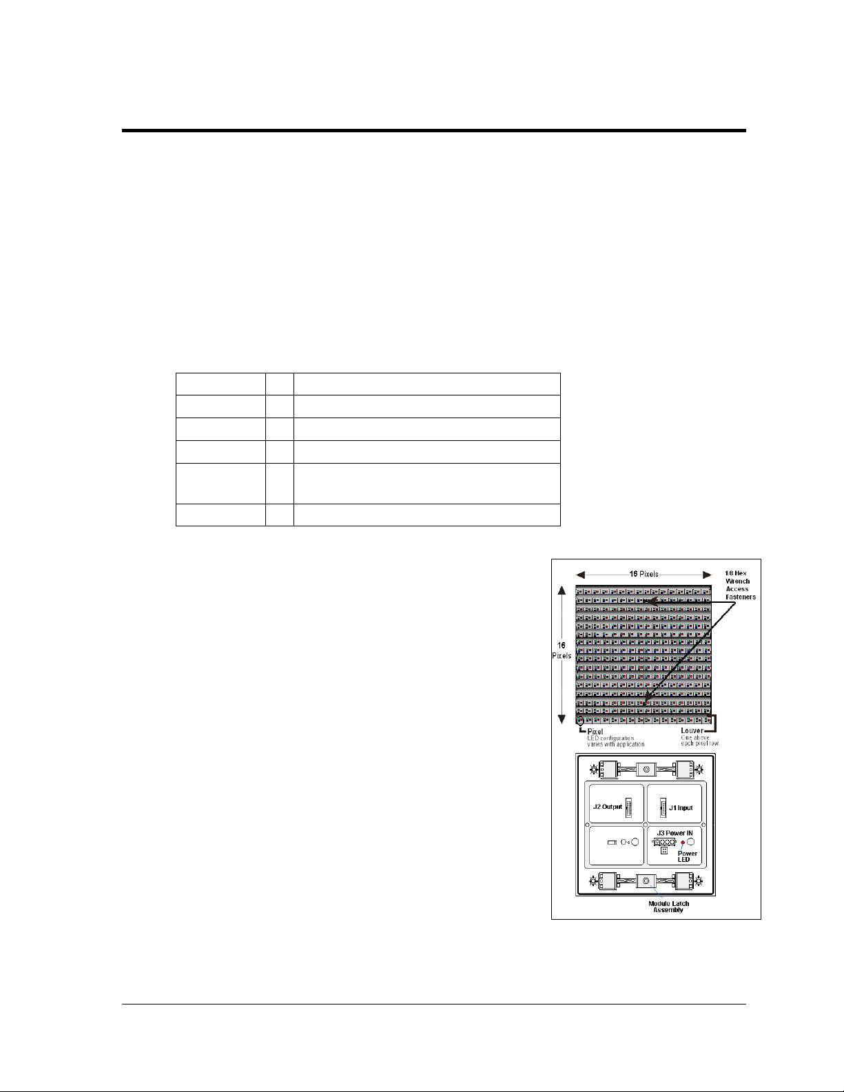
A module is the building block of the Galaxy
Each module measures 16 pixels high by 16 pixels wide. By
placing modules next to one another, a display of any size
can be designed and built. Individual modules can be easily
removed from the display, if required.
A typical display system is run with a Windows
personal computer (PC) running Venus
®
Venus
Windows
1500 is a software package that runs under
®
98, ME™, NT® 4.0, 2000, XP or Vista
Home/Professional operating systems on an IBM
compatible computer. This software can manage up to 240
displays on one network. Refer to the Venus
operations manual (ED-13530) for installation and
operation of the Venus
These displays are offered as double-face units. The face
containing the blue dot and light sensor is called Face A
(Primary) and the opposite side is referred to as Face B.
Refer to Figure 2 and Figure 3.
Outdoor louvered Galaxy display
Number of pixel rows high
Number of pixel columns long
20 mm pixel to pixel spacing
LED color, R (Red), A (Amber),
RGB (Red, Green, Blue - 32,000 color)
Double-face display
®
display.
®
®
1500
-based
®
-
®
1500 software.
®
1500 software.
Figure 1: Module, Front and Back
Overview of the Displays 1
Page 10
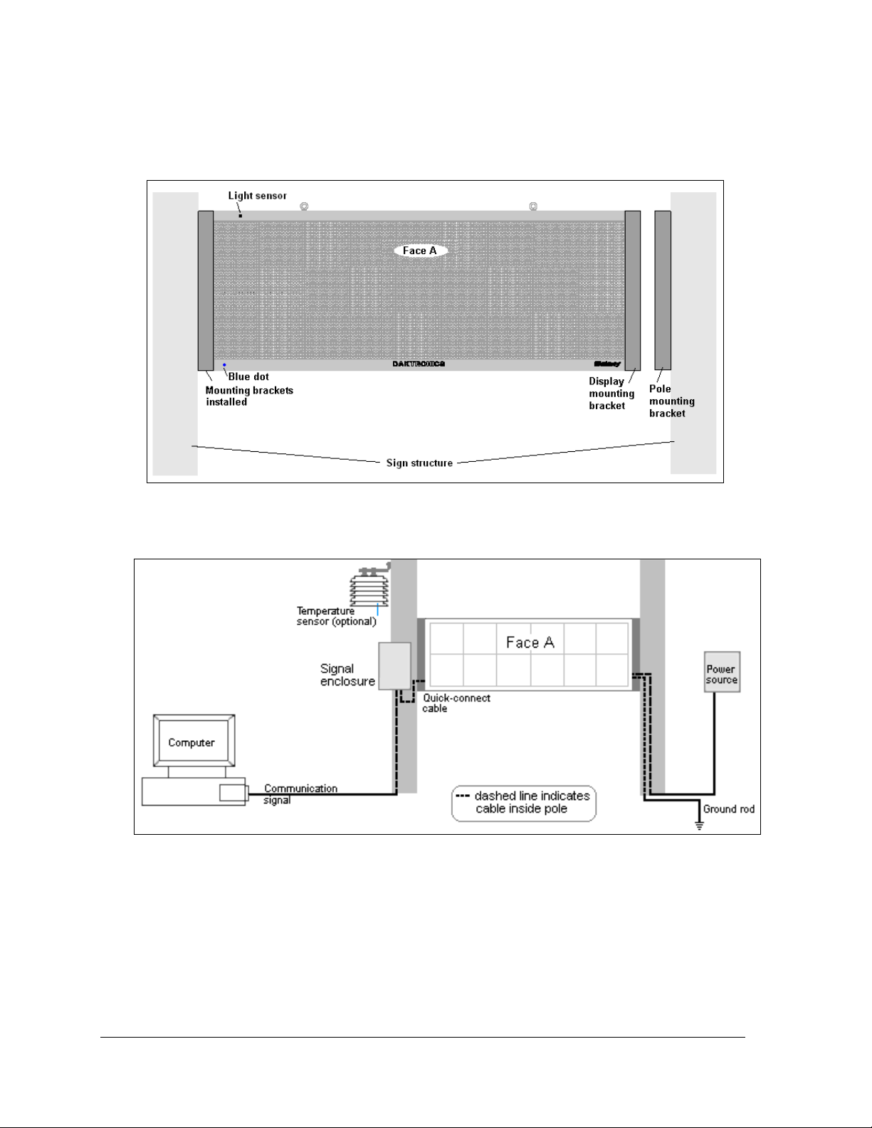
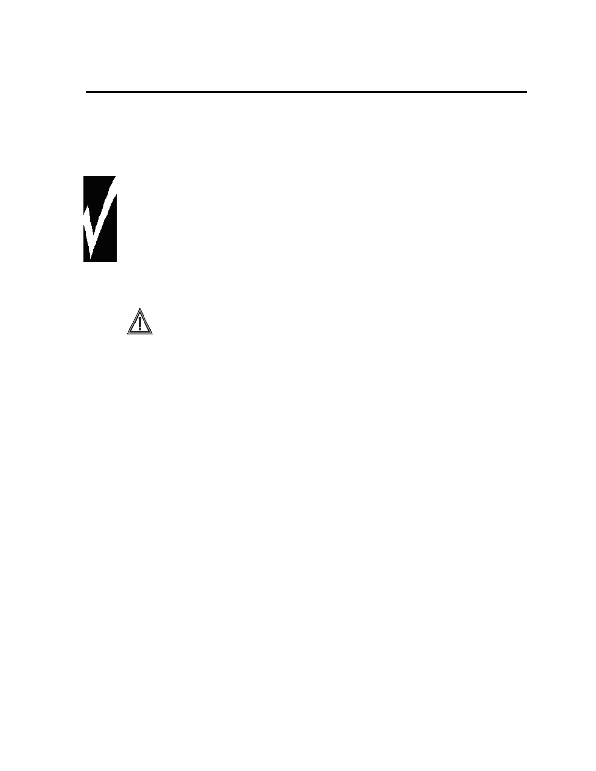
Display terminology is illustrated in Figure 2. The diagram in Figure 3 gives an overview of the
basic display set-up. These diagrams will help in the understanding the information in this
display manual.
Figure 2: Display Terminology
Figure 3: Basic Display Set-up
2 Overview of the Displays
Page 11
Section 2: Mechanical Installation
Read the Mechanical, Power, and Signal Installation sections before installing the display(s).
Reference Drawing:
Install, AF-3400-**x**-20-DF ............................................................................... Drawing B-310431
Daktronics engineering staff must approve any changes that may affect the weathertightness of the display. If any modifications are made, detailed drawings of the changes
must be submitted to Daktronics for evaluation and approval, or the warranty may be void.
Daktronics is not responsible for installations or the structural integrity of support
structures done by others. The customer is responsible for ensuring that a qu alified
structural engineer approves the structure and any additional hardware.
2.1 Support Structure Requirements
The installer is responsible for ensuring that the mounting structure and hardware
are capable of supporting the display, and the structure follows all local codes.
Because every installation site is unique, no single procedure is approved by Daktronics for
mounting Galaxy
only and may or may not be appropriate for this particular installation. Refer to Figure 3 for
basic display set-up. Refer to Drawing B-310431 for installation details.
A qualified individual must make all decisions regarding the mounting of this display.
Support structure design depends on the mounting methods, display size, and weight. In
general, both faces of the display need to be unobstructed to allow for air flow and internal
access. Also keep in mind the location of the mounting plates and the power/signal
termination shrouding on the sides of the display. Display height and wind loading are also
critical factors to be considered. The following information can be found in the Shop
Drawings listed here:
• Size and weight information
• Mounting hardware information
®
displays. The information contained in this section is general information
List of Shop Drawings
A Shop Drawing was provided when the display was ordered. However, if one is needed,
use this list to find the correct number to request from Daktronics Customer Service. Note
that they are listed by pixel matrix size.
Shop Dwg, AF-3400-32x80-20-DF* ............................................................. Drawing B-308603
Shop Dwg, AF-3400-32x96-20-DF* ............................................................. Drawing B-308106
Shop Dwg, AF-3400-32x112-20-DF* ........................................................... Drawing B-308604
Shop Dwg, AF-3400-48x112-20-DF* ........................................................... Drawing B-306282
Shop Dwg, AF-3400-48x144-20-DF* ........................................................... Drawing B-308605
Shop Dwg, AF-3400-64x144-20-DF* ........................................................... Drawing B-308606
Mechanical Installation
3
Page 12
Pre-installation Checklist
Verify the following before proceeding with installation:
• The display is in good condition after shipping and uncrating.
• A straight and square mounting structure is provided for the display.
Height variation in any four-foot horizontal section may not exceed ¼-inch.
• Adequate support is provided for the display so that the structure will not yield at
any unsupported points after mounting.
• Clearance of 4" of unobstructed space above the top of the display is allowed to
remove the eyebolt. Note: No clearance is required once the eyebolts are removed.
• Clearance in front of and below the display cabinet is maintained to allow
unobstructed air flow through the vents and fans and to allow access to internal
components.
2.2 Display Lifting
The installer is responsible for ensuring that the installation adequately meets local
codes and standards, including safe, adequate mounting hardware and
procedures.
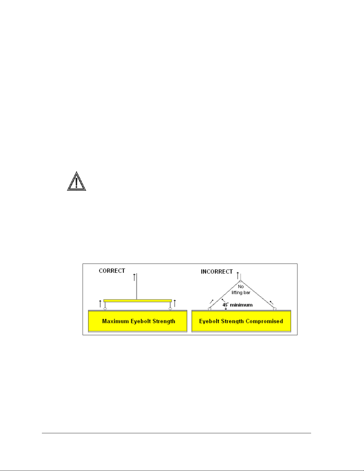
Note: In order to maintain the structural integrity of the display cabinet, the 90° angle
between the cabinet and the lifting method must be maintained.
1. Lift the display into position on the support structure following the guidelines in
Figure 4.
Do not attempt to permanently support the display by the eyebolts.
Figure 4: Correct/Incorrect Lifting Procedures
2. Weld or use ½" Grade-5 bolts and hardware to secure the mounting brackets to the
display and support structure as shown in Drawing B-310431 found in Appendix A.
3. Refer to Section 3 and the appropriate communication manual for information on
routing power and signal to the display.
4. After installation is complete, carefully inspect the display for any holes that may
allow water to seep into the display and seal any openings with silicone.
If the eyebolts on the top of the display have been removed, plug the holes with bolts
and the rubber-sealing washer that was removed with the eyebolt, unless an overhead
structure protects the area.
4
Mechanical Installation
Page 13
2.3 Display Mounting
To mount the display, follow these steps. For additional information, refer to the quick guide
ED-17986 and to Drawing B-310431.
1. Verify the distance between sign mounting poles. Consult the chart on Drawing B-
310431 for dimensions.
2. Drill into the poles at the designated places to provide access for power and signal
cables. Debur holes to prevent wire damage.
3. Attach mounting brackets to sign poles.
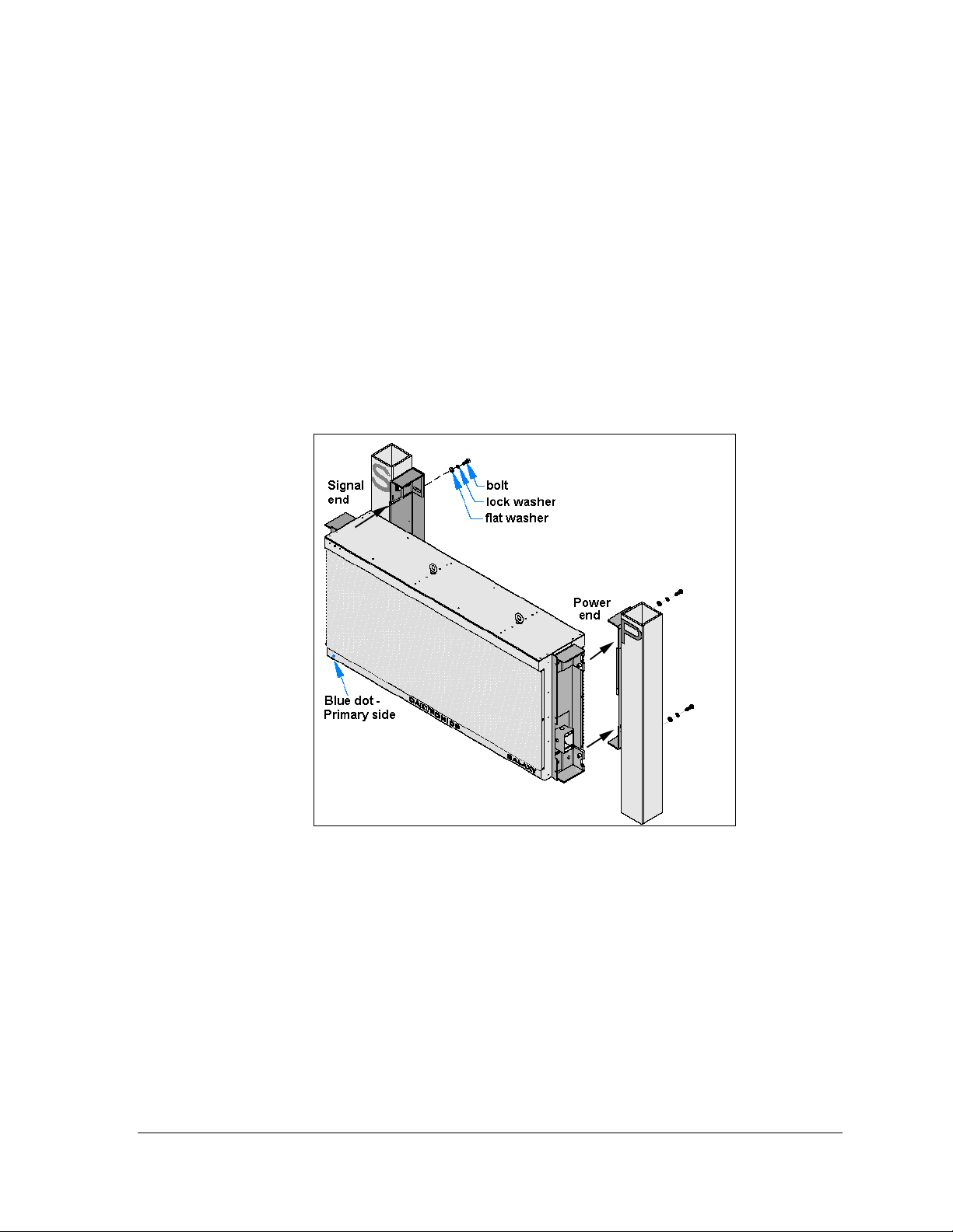
4. Verify the primary face of the display by locating the blue dot in the lower left corner
of the cabinet. Note that signal will enter on the left end of Face A and power will
enter on the right end.
5. Slide the display mounting brackets into the pole mounting brackets on the sign
poles and attach them.
Figure 5: Installing Display into Sign Poles
6. Bring power cable through the right sign pole and terminate at the J-box on the right
end of the display; refer to Section 3.
7. Bring signal interconnect cable through the left sign pole and plug into the
interconnect jack on the left end of display; refer to Section 4.
8. Use one or two cover plates (as required) to enclose the shrouds. Ensure that these
areas are completely protected.
2.4 Optional Temperature Sensor Mounting
If a temperature sensor will be used with this display, see Appendix B for mounting and
signal connections.
Mechanical Installation
5
Page 14

Page 15
Section 3: Power Installation
Read the Mechanical, Power, and Signal Installation sections before installing the display(s).
• Only a qualified individual should terminate power and signal cable at this Daktronics
display.
• All proposed changes must be approved by Daktronics engineering staff or the warranty
will be rendered null and void.
Reference Drawing:
Power Specs, AF-3400-20-DF-* ...................................................................... Drawing A-305814
3.1 Conduit
Daktronics does not include the conduit. Separate conduit must be used to route:
• power.
• signal IN wires to the signal termination enclosure, when applicable.
• signal OUT wires to a second set of displays.
The power J-box and the power end of the display are provided with 3/4” threaded holes for
use with conduit. Unthreaded knockout holes are provided in the signal enclosures as well. If
not using the provided enclosures, use the openings provided in the display cabinet.
3.2 Overview of Power/ Signal Connection
Following is a brief summary of the power and signal connections to the display.
1. Openings are provided on the display for termination of both signal and power. If
the installation does not allow for the use of the power J-box, refer to Section 3.5 for
diagrams on internal power termination.
2. Possible methods for signal termination are shown in the manual for the specific
communication type.
3. Route power to the display through a fused disconnect switch capable of opening all
ungrounded power conductors. Install this disconnect within the line-of-sight of any
personnel performing maintenance on the display. If the disconnect is located out of
sight of the display, it must be capable of being locked in the open position.
Note: Displays are equipped with supplemental protection devices that carry a UL1077
(IEC 60947, VDE 660) rating. These devices are only intended to protect the components
within the display. Suitable devices must be used for the equipment and feeders
supplying power to the display.
4. Power conductors from the disconnect to the display should be routed through
conduit in agreement with local code.
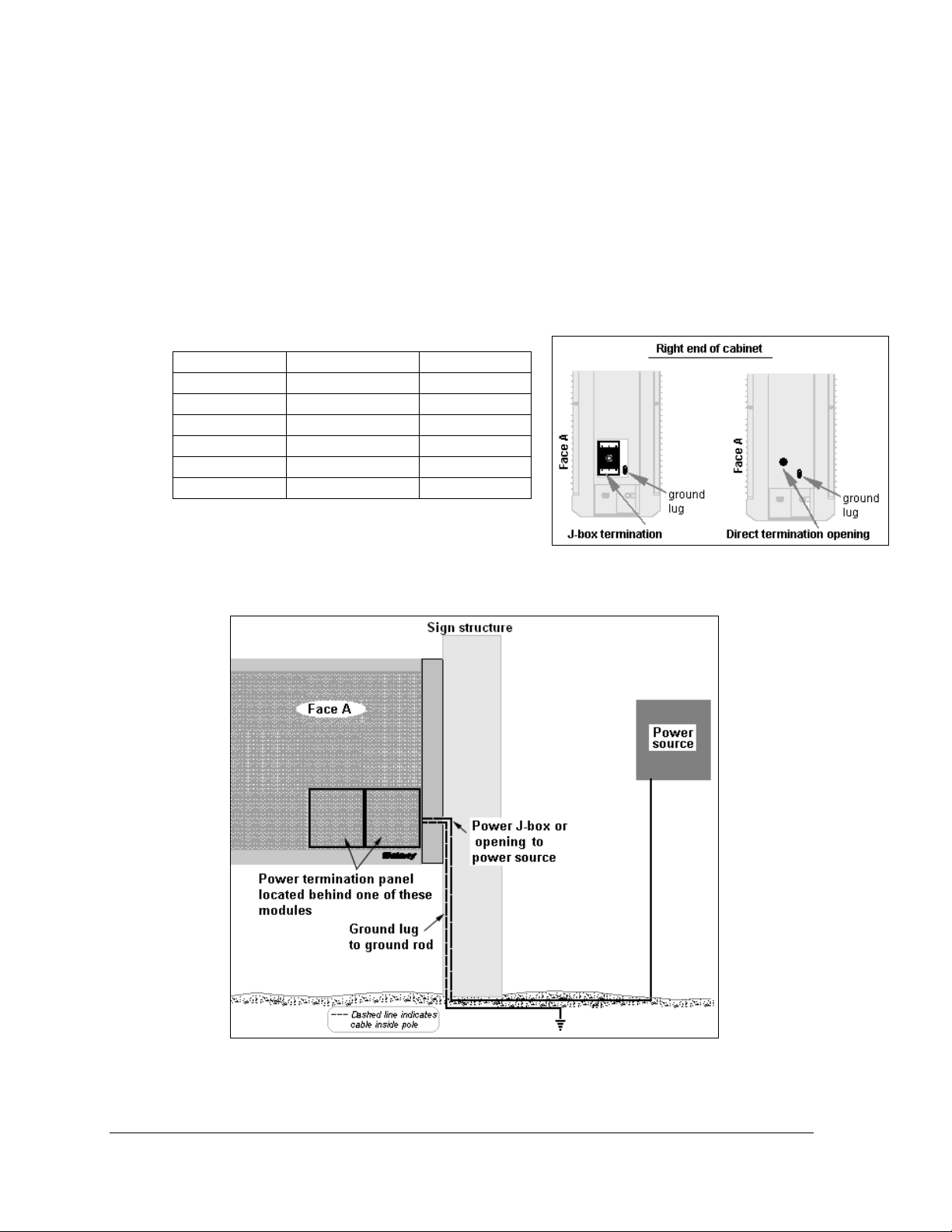
5. Display power will terminate to the display at the power termination J-box or
directly to the power termination panel located on the right end of Face A.
Power Installation
7
Page 16

6. Connect the grounding electrode conductor at the grounding lug near the J-box on
the right end of Face A.
7. Signal cable is routed to the signal termination enclosure. A grounding electrode
may also be connected there (when required).
8. Signal into the enclosures must be routed through 1/2"conduit.
9. The signal quick-connect cable from the enclosure to the display is routed into the
shrouding on the left end of the display cabinet.
Note: Daktronics strongly recommends that the quick-connect cable be secured to protect it
from weather and vandalism.
3.3 Power Requirements
Conductors of circuits delivering power to a Daktronics display shall be sized in
accordance with NEC and local electrical codes so that the power distribution
system is capable of delivering full load power to the display while maintaining a
voltage within 5% of the utility nominal voltage.
Each display uses a 120VAC or 120/240 VAC single-phase power source. Proper power
installation is imperative for proper display operation. Power specifications for various
display sizes can be found on Drawing A-305814 in Appendix A. The following sub-sections
provide details for display power installation.
Main Disconnect
The National Electrical Code requires the use of a lockable power disconnect near the
display. Provide a lockable disconnect switch (knife switch) at the display location so that all
power lines can be completely disconnected. Use a 3-conductor disconnect so that both hot
lines and the neutral can be disconnected. The main disconnect should be mounted at or near
the point of power supply connection. A main disconnect is to be provided for each supply
circuit to the display.
The disconnecting means must be located in a direct line-of-sight from the display or outline
lighting that it controls. This requirement enables a worker to keep the disconnecting means
within view while working on the display.
Exception: Disconnect components that are capable of being locked in the open position may
be located elsewhere.
8
Power Installation
Page 17
3.4 Grounding
These displays are installed with ground and neutral conductors provided. The power cable
must contain an isolated earth-ground conductor.
Under this circumstance, do not connect neutral to ground at the disconnect or at the display.
This would violate electrical codes and void the warranty. Use a disconnect so that all hot
lines and neutral can be disconnected. The National Electrical Code requires the use of a
lockable disconnect within sight of or at the display.
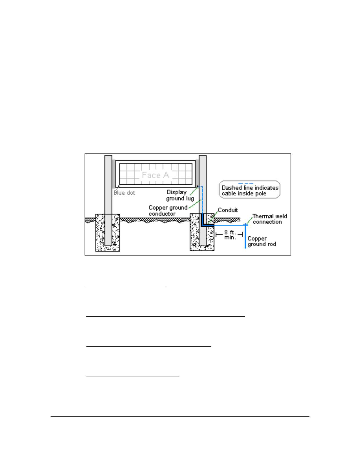
The display system must be connected to earth-ground (Figure 6). Proper grounding is
necessary for reliable equipment operation. It also protects the equipment from damaging
electrical disturbances and lightning. The display must be properly grounded, or the
warranty will be void.
Figure 6: Correct Grounding
Important points about grounding:
• Follow local and national codes
region to region and from conditions present at the site. Consult the National Electrical
Code and any local electrical codes that may apply.
• Support structure cannot be used as an earth-ground electrode
generally embedded in concrete. If embedded in earth, the steel is either primed or it
corrodes, making it a poor ground.
• One grounding electrode for each display cabinet
each display cabinet. Other grounding electrodes as described in Article 250 of the
National Electric Code may be used.
• Resistance to ground 10 ohms or less
performance. If the resistance to ground is higher than 10 ohms, it will be necessary to
install additional grounding electrodes to reduce the resistance. The grounding
electrode should be installed within 25 feet of the base of the display. The grounding
electrode must be connected to the ground lug on the back of the display.
: The material of an earth-ground electrode differs from
: The support is
: One grounding rod is necessary for
: This is required by Daktronics for proper display
Power Installation
9
Page 18
3.5 Power Connection
Two options are possible for terminating power to the display, depending on the size of the
display (Figure 7). Installation instructions for both are provided in this section.
Option 1 - J-box: use the power termination enclosure on the end of the cabinet.
Option 2 - Direct: use provided 3/4" conduit opening to go directly to the power
termination panel inside the display cabinet.
Refer to this chart for the method used in a particular size.
Matrix size Monochrome RGB
32 x 80 J-box J-box
32 x 96 J-box J-box
32 x 112 J-box J-box
48 x 112 J-box Direct
48 x 144 J-box Direct
64 x 144 Direct Direct
Figure 7: Power Termination Options
10
Figure 8: Power Installation Wiring
Power Installation
Page 19

Option 1: J-box Termination
1. Route power cable through the sign pole to the right end of the display (Figure 8).
2. The power termination enclosure will contain two or three wires plus a ground
coming from the interior of the display. These wires are pre-terminated to the power
termination panel inside the display.
3. Connect the wires coming from the display interior to the power wires using wire
nuts. Refer to Figure 9 for 120 V termination and
Note: The following colors are used for the pre-terminated wires:
120 volt
240 volt
x Line 1 – Black x Line 1 – Brown
x Neutral - White x Neutral - Blue
x Grounding – Green-Yellow x Grounding– Green-Yellow
Figure 10 for 240 V termination.
Figure 9: 120 V Power Termination
Figure 10: 240 V Power Termination
Figure 11: 120/240 V Power Termination
Power Installation
11
Page 20

Option 2: Direct Termination
1. Refer to the Schematic drawing for the specific display size (in Appendix A) to locate the
power termination panel in the lower right corner of the cabinet (Figure 8).
2. Remove the module in front of the power termination panel as explained in Section 6.1.
3. Route cable through the sign pole to the right end of the display. Use the provided
opening for access to the power termination panel, being careful not to damage internal
components.
4. Make the connections as shown in the figures for the appropriate circuit size and type.
Generally, the wiring connects as follows:
• Hot to circuit breaker 1 (line side).
• If present: Hot to circuit breaker 2 (line side in three-wire connections).
• Neutral to gray terminal block (line side).
• Ground to green/green yellow terminal block.
12
Figure 12: One-breaker Circuit for 120 V and 240 V
Figure 13: Two-circuit Power Termination
Power Installation
Page 21

Figure 14: Four-circuit 120 V
Termination
3.6 Power Routing in the Display
Figure 15: Six-circuit 120-240 V
Termination
A general power routing, shown in Figure 16, is summarized as follows. The numbers in this
list correspond with the numbers in the diagram.
1. Power terminates to the J-box on the right end of the display or internally to the
power termination panel.
2. If terminating at the J-box, power continues through pre-terminated wires to the
power termination panel, which includes the transformer and filter.
3. From the termination panel, power travels through the transformer which adjusts
power to appropriate voltage for use by the controller.
4. Power is routed from the power panel to the power supplies/filters which run the
modules.
5. Power is also sent to the fans and to the thermostat.
Note: Power supplies are preset to proper voltage levels. Depending on the pixel count and
LED color, either 3.6 VDC or 5.3 VDC power supplies are used to power the modules.
Contact Daktronics Customer Service for correct voltage settings.
Power Installation
13
Page 22

Figure 16: Power Routing Summary
14
Power Installation
Page 23

Section 4: Signal Installation Overview
Daktronics Galaxy® displays are equipped to receive many types of communication. The following
sections include a brief description of each available communication type. Also included is a list of
troubleshooting tips to check that the display is connected and configured correctly.
For specific details on installing the signal, consult the quick guide and the manual. These were
included in the shipment of the communications equipment. Each type is listed below with its
manual number.
Note: These are the standard communication types. However, each site is unique and may include
additional equipment. If problems arise, contact the display’s seller, service company, or Daktronics
Customer Service.
Each of these communication types will
terminate to the location shown in Figure 17.
The signal quick-connect inputs and optional
openings are available on the left end of the
cabinet.
Communication
Type
RS-422
Fiber
Radio
RS-232
Ethernet
Fiber Ethernet
Ethernet Radio
Modem
Communication
Manual ED#
ED-14742
ED-14743
ED-13932
ED-14739
ED-14745
ED-14746
ED-16483
ED-14744
Signal Installation
Figure 17: Quick-connect Signal Inputs
15
Page 24

4.1 RS-422 Communication
If the communication system is RS-422, look for:
• a signal converter near the computer.
• wires from the signal converter connecting to an enclosure at the display.
Figure 18: RS-422 Communication Layout
Connections
• Computer to signal converter − six-foot serial cable with 9-pin plug connecting to
computer port or USB adaptor and 25-pin plug connecting to the signal converter at J1,
RS232 IN.
• Signal converter plugged into a 120 volt AC outlet.
• Signal converter to surge board at display − four individual wires from green Phoenix
plug at either J4 or J5 run to Phoenix plug on surge board.
• Surge board to display − quick-connect cable from enclosure to the middle jack on
display side.
16
Troubleshooting
Component Check
Cable
Connections
Diagnostic
LEDs
Display Power • The display is either running a message or showing a single pixel flashing in the
Software • The software and the display are set for the same network address.
• The serial cable connects the computer to the signal converter.
• All the wires are connected at the signal converter and the surge board. They need
to be making good electrical contact with the metal, no interference.
• The color sequence of the wires should be the same to both signal converter and
surge board (e.g. black, white, red, green and black, white, red, green).
• The quick-connect cable is connected from the enclosure to the middle jack on the
side of the display.
• The green LED on the signal converter should be on when plugged into power.
• The red transmit and amber receive LEDs will flash when sending and receiving
signal from the display; otherwise they are off.
bottom right corner of the display when power is on.
• Refer to the software manual for other possible conditions.
Signal Installation
Page 25

4.2 Fiber Optic Communication
If the communication system is fiber optic, look for:
• a signal converter near the computer.
• fiber-optic cables connecting the signal converter to an enclosure at the display.
Figure 19: Fiber Serial Communication Layout
Connections
• Computer to signal converter − six-foot cable with 9-pin plug connecting to computer
port or USB adaptor and 25-pin plug connecting to the signal converter at J1, RS232 IN.
• Signal converter plugged into a 120 volt AC outlet.
• Signal converter to fiber optic board at display − two individual cables connect to signal
converter at either J4 and J5 or J3 and J2; other end runs to fiber optic board at display, J4
and J5.
• Fiber optic board to display − quick-connect cable from enclosure to the top jack on
display side.
DO NOT SHARPLY BEND fiber-optic cable at any point along the fiber cable.
Troubleshooting
Component Check
Cable
Connections
Diagnostic
LEDs
Display Power • The display is either running a message or showing a single pixel flashing in the
Software • The software and the display are set for the same network address.
• The serial cable is connected from the computer to the signal converter.
• Both fiber optic cables are connected at the signal converter and the fiber board.
• The cable from the enclosure i s connected to the top jack on display side.
• The green LEDs on the sig nal converter and the fiber optic board in the enclosure
will be on when they have power.
• The red transmit and amber receive LEDs on both components will flash when
sending and receiving signal from the display; otherwise they are off.
bottom right corner of display when power is on.
• Refer to the software manual for other possible co nditions.
Signal Installation
17
Page 26

4.3 Radio Communication
If the communication system is radio, look for:
• a radio j-box near the computer.
• a server radio outside the building and a second radio at the display.
Figure 20: Radio Communication Layout
Connections
• Computer to radio j-box − six-foot cable with 9-pin plugs on both ends, one connecting to
computer port or USB adaptor and the other plug connecting to radio j-box at “DB9
Female V1500 PC Connect”.
• Radio j-box 12 volt power adapter plugged into outlet.
• Radio j-box to radio transmitter on building − Phoenix plug on side of j-box to 6-pin
Phoenix plug inside radio transmitter.
• Radio signal between transmitter and receiver.
• Radio receiver to display − quick-connect cable from receiver to top jack on display side.
Troubleshooting
Component Check
Cable
Connections
Diagnostic
LEDs
Display
Power
Software • The software and the display are set for the same network address.
• The cable connects the computer to the radio j-box.
• All the wires are connected at the radio j-box and at the “server” radio; the
wires make good electrical contact with the metal, no interference.
• The color sequence of the wires should be the same to both the radio j-box
and the server (e.g. black, white, red and black, white, red).
• The cable is connected from the radio client to the top jack on side of display.
• The green LEDs will be on when the radio j-box has power.
• The red and amber transmit and receive LEDs will flash when sending and
receiving signal from the display; otherwise they are off.
• The display is either running a message or showing a single pixel flashing in
the bottom right corner of the display when power is on.
• Refer to the software manual for other possible co nditions.
18
Signal Installation
Page 27

4.4 RS-232 Communication
If the communication system is RS-232, look for:
• no indoor connectors.
• one enclosure at the display.
This communication type is designed to work over short distances and typically connects to
an indoor display.
Figure 21: RS-232 Communication Layout
Connections
• Computer to display enclosure − six-foot serial cable with 9-pin plug into laptop
computer or USB adaptor and a 25-pin jack into enclosure.
• Enclosure to display − quick-connect cable (maximum 25 feet) from back of enclosure to
top jack on side of display.
Troubleshooting
Component Check
Cable
Connections
Display
Power
Software • The software and the display are set for the same network address.
• The serial cable is conn ected from the laptop to the enclosure.
• The cable is connected from the enclosure to the top jack on the side of
the display.
• The display is either running a message or showing a single pixel flashing
in the bottom right corner of the display when power is on.
• Refer to software manual for other possible conditions.
Signal Installation
19
Page 28

4.5 Ethernet Communication
If the communication system is Ethernet, look for:
• a network card in the computer connecting to a network switch.
• a network jack similar to an oversized phone jack.
Figure 22: Ethernet Communication Layout
Connections
• Computer to network − RJ45 cable from computer port to network server in building.
• Network switch/router to surge board at display − RJ45 cable from switch to surge board
in enclosure at display (maximum cable distance 300 feet).
• Enclosure at display to display − quick-connect cable from enclosure to middle jack on
side of display.
Troubleshooting
Component Check
Cable
Connections
Display
Power
Software • The software is configured for TCP/IP communication.
• The network cable connects the computer to the network switch/router.
• An RJ45 cable from server is connected to the input jack o n Ethernet surge
board.
• The quick-connect cabl e runs from enclosure to middle jack on display side.
• The display is either running a message or showing a single pixel flashing in
the bottom right corner of the display when power is on.
• The software and the display are set for the same network address.
• Refer to the software manual for other possible co nditions.
20
Signal Installation
Page 29

4.6 Fiber Ethernet Communication
If the communication system is fiber Ethernet, look for:
• an indoor media converter connected to the network and to fiber cable.
• a second media converter outdoors located in an enclosure at the display.
Figure 23: Fiber Ethernet Communication Layout
Connections
• Computer to network − RJ45 cable from computer port into network switch/router.
• Network switch to first media converter − RJ45 cable from network switch/router into
media converter.
• Media converter’s 9-volt power adapter plugged into outlet.
• Indoor media converter to outdoor media converter − two fiber-optic cables run from
indoor media converter to second converter in the enclosure at display.
• Enclosure to display − quick-connect cable to the middle jack on display side.
DO NOT SHARPLY BEND fiber-optic cable at any point along the fiber cable.
Troubleshooting
Component Check
Cable
Connections
Diagnostic
LEDs
Display
Power
Software • The soft ware is configured for TCP/IP communication.
• The cable is connected from the computer to the network switch/router.
• The network cable con nects from network switch to media converter in building.
• The indoor media converter power adapter is plugged in.
• The fiber cables connect from the first media converter to the second one at
display. The “out” arrow on one will connect to an “in” arrow on the other.
• The cable is connected from the enclosure to middle jack on display side.
• Each media converter has a green power LED on, indicating power.
• When media converter trans mits data, the “link” is on and RX LEDs flash.
• The display is either running a message or showing a single pixel flashing in the
bottom right corner of the display when power is on.
• The soft ware and the displ ay are set for the same network address.
• Refer to the software manual for other possi ble conditions.
Signal Installation
21
Page 30

4.7 Ethernet Bridge Radio Communication
If the communication system is a wireless Ethernet bridge radio, look for:
• a DC injector connected to the network, server radio, and a 120 VAC outlet.
• a server (transmitter) radio mounted on the building and a client (receiver) radio at
the display.
Note: This system is referred to as Ethernet "bridge" communication because it requires a pair
of matched radios to create a signal connection or bridge.
Figure 24: Ethernet Bridge Radio Layout
Connections
• Computer to network − RJ45 cable from computer port into network server in building.
• Network switch to DC injector - RJ45 cable from network to "DATA IN" jack.
• Wall power adapter - DC injector power adapter to 120 VAC outlet.
• DC injector to server radio - RJ45 cable from "P+DATA OUT" to server radio.
• Server radio to client radio - clear line of sight for signal transmission.
• Client radio to display − quick-connect cable to the middle jack on display side.
22
Troubleshooting
Component Check
Cable
Connections
Diagnostic
LEDs
Display
Power
Software • The software and the display are set for the same network address.
• A cable connects the computer to the network switch/router.
• A cable runs from the network switch to the DC injector.
• The DC injector is plugged into a 120 VAC outlet.
• A cable runs from DC injector to server radio.
• Maximum distance from switch to server radio is 300 feet (100M)
• The quick-connect cable runs from client radio to top jack on side of display.
• The DC injector's green LED should be on, indicating power.
• Both radios have internal LEDs. Refer to the Wireless Ethernet manual for
their specifications.
• The display is either running a message or showing a single pixel flashing in
the bottom right corner of the display when power is on.
• Refer to the software manual for other possible conditions.
Signal Installation
Page 31

4.8 Modem Communication
If the communication system works with a modem, look for:
• a modem (internal or external) at the computer that connects to a phone jack.
• a phone line connects to the display.
Figure 25: Modem Communication Layout
Connections
• Computer modem (internal or external) to phone jack on wall − phone cable plugs into
both.
• Phone jack to modem at display − signal runs on local telephone lines.
• Modem board in enclosure to display − quick-connect cable from enclosure to top jack
on display side.
Troubleshooting
Components Check
Cable
Connections
Diagnostic
LEDs
Display Power • The display is either running a message or showing a single pixel flashing in the
Software • The software and the display are configured for dial-up communication and the
• The phone line is connected from the modem at the computer to the phone jack.
• The t wo phone wires are connected at the modem board (Wire color is
determined by the phone company.)
• The wires are making good el ectrical contact with the metal, no interference.
• The quick-connect cable is connected from enclosure to top jack on display side.
• The modem in the enclosur e has the green LED on, indicating power.
• The bottom red LED (carrier detect) is on when the modems are connected.
• Transmit and receive LEDs flash when sending and receiving signal over the
telephone line; otherwise, they are off.
bottom right corner of the display when power is on.
phone number is correct.
• Refer to the software manual for other possible co nditions.
Signal Installation
23
Page 32

Page 33

Section 5: Start-up Procedure
Before starting up the display, go over this checklist to ensure that all parts are ready to operate
correctly. Figure 26 shows the basic display components referred to in each step.
5.1 Start-up Checklist
DIs power connected to the display?
The power conduit will leave the display from the right end of Face A and connect to a
power source either on the display structure or inside a building. Refer to Figure 26 for
approximate location of the power cable or conduit.
DIs the control computer connected to the display?
Some type of communication line or wireless device will send signal between the control
computer and the display, depending on the communication method. Refer to Section 4 for
assistance with identifying the communication type.
DIs the computer software set up to work with the display?
The software manual provides the information necessary to allow the computer to
communicate with this display. Consult the software manual's Configuration section for
correct set-up.
Figure 26: Basic Display Set-up
Start-up Procedure
25
Page 34

5.2 Start-up Sequence
Each time the display is turned on, an initialization sequence will run. The information in the
second column will then be shown on the display.
Note: The Xs refer to numbers that may vary for each display, such as the hardware address.
Topic Information shown
1. Product Name • Galaxy®
2. Display Size • Row x Column
3. Shading • 64 Mono/RGB
4. Bootloader Version • OS X.XX
5. Firmware Number • ED-13305
6. Firmware Revision • Rev X.XX
7. Hardware Address • HW:XX
8. Software Address • SW:XX
9. IP Address: • (default: IP: 172.16.192.25)
10. Subnet Msk: • (default) Msk: 255.255.0.0)
11. COM1 Configuration • C1:V15
12. COM 2 Configuration • C2: RTD
13. Socket 3001: • IP 3001: V15
14. Socket 3002: • IP 3002: RTD
15. Line Frequency • CLK: AUTO (60)
16. Display Description • Galaxy # rows x # columns
After this sequence is complete, the display will blank. A single pixel will flash in the lower
right hand corner of the display to show that the display has power but no messages are
currently running.
(modem: C1:V15 if a modem is present)
26
Start-up Procedure
Page 35

Section 6: Maintenance
Important Notes:
• Power must be turned off before any repair or maintenance work is done on the
display.
• Qualified service personnel must make any access to internal display electronics.
• The Daktronics engineering staff must approve ANY changes made to the display.
Before altering the display, detailed drawings for the proposed modifications must be
submitted to the Daktronics engineering staff for evaluation and approval or the
warranty will be rendered null and void.
The internal components in Daktronics Galaxy® AF-3400 series double-face displays are accessible by
removing the modules from Face A (the side with the blue dot and light sensor). The display may
need to be opened to perform maintenance or for troubleshooting. The following diagram (Figure 27)
shows the typical location of internal components. Refer to the Schematic Drawing for the specific
display size to verify component location.
Note: Power supplies are labeled A and B to denote the face of the display on which their
corresponding modules are located. In other words, power supplies labeled "A" supply power to the
modules on Face A of the display.
Figure 27: Location of Internal Components in 32 x 80 Display
Maintenance
27
Page 36

6.1 Display Access
To gain access to the interior of a display, single modules are able to be removed. Refer to
Figure 27 to locate the internal components which may need to be accessed. In the case of
fans, consult the Shop Drawing for the display size. The module in front of the specific
component may be removed to perform maintenance or for troubleshooting.
To access the interior of the display, perform the following steps:
1. Turn off power to the display.
2. Locate the latch access fasteners on the module
(Figure 28). One is centered below the second
row of pixels and one is centered above the
bottom two rows.
3. With a 1/8" hex wrench, turn the latch access
fasteners a quarter turn counterclockwise. Gently
pull the module far enough forward to reach
behind the back and disconnect the power and
ribbon cables (Figure 29). Note the cable
connections so they can later be reconnected
correctly.
4. Disconnect the two ribbon cables from the
module by spreading the tabs on the sides and
then lifting the cable head from the jack. Note
how they are connected to the back.
5. Unplug the power cable by squeezing the
tabs on the sides of the plug head and
pulling out.
6. When ready to reinstall the module,
reconnect the cables to the module, making
sure that the tabs are tightly pushed
against the cable head. Carefully push the
ribbon wires back into the cabinet so they
are clear of the module edges.
7. Place the module into its proper location,
checking that the weather stripping is in place. Latch the module both top and
bottom using the hex wrench.
Note:
• The weather-stripping on the back edge of the module must be intact and in good
condition if it is to prevent water from seeping into the display.
• The module latches must be fully engaged to create a watertight seal around the edge of
the module. The module should be firmly seated against the display when the latches are
fully engaged.
Figure 28: Module Access Locations
Figure 29: Removing a Module
28
Maintenance
Page 37

6.2 Ventilation System/ Fans
Frequency of Inspection
Ventilation fans are located on the bottom of the display. They pull
air into the cabinet from the lower vent, exhausting it out the top
vent (Figure 30).
Fans should be checked every time the display is opened for service
or at a minimum of annually. Fans should be checked more often if
the display is located in a dusty or harsh weather environment.
Fan Blades
Check the fan blades for dirt and debris, cleaning them and the
inside of the display if necessary. Fan blades must be kept clean to
maintain fan efficiency and to ensure proper cooling. Spin the fan
blades with a pen or pencil to ensure that the bearings are free and
the fan is still in balance.
Air Flow
To check the operation of the fans, open the display to expose the
thermostat in the top right corner of Face A behind the first
module (Figure 31). Push the bypass button on the thermostat
enclosure to temporarily turn on the fans. If a fan does not rotate
or does not operate smoothly, replace it.
Check the intake and exhaust vents and remove any dust or
debris that may be obstructing air flow. Hold your hand or a
piece of lightweight paper in front of the vents to detect air
movement.
Figure 30: Ventilation Fans
Figure 31: Thermostat
6.3 Annual Inspection
A yearly inspection should be completed to maintain safe and dependable display operation.
The display will need to be opened to visually inspect the cabinet interior and the
components. Refer to Section 6.1 for these directions. The inspection should address the
following issues:
Maintenance
Inspection item Possible corrective measures
Loose bolts, screws, rivets Tighten or replace, as required
Water intrusion or stains
Paint corrosion by footings, tie
points, ground rods
• Replace weather-stripping
• Tighten module latches
• Place silicon sealant around all locations
where water might enter
• Replace damaged electronic components
• Check the metal for structural integrity.
• Replace and/or repaint as necessary.
29
Page 38

Page 39

Section 7: Diagnostics and Troubleshooting
Safety Precautions
• Disconnect power when servicing the display.
• Do not modify the display structure or attach any panels or coverings to the display
without written consent of Daktronics.
7.1 Controller Diagnostics
The controller is located in the left end of Face A, second row from bottom, as labeled in
Figure 32. Since the controller is inside the display, a module will need to be removed to
view the diagnostic LEDs. To access the interior of the display, refer to Section 6.1 for
instructions.
Figure 32: Interior Component Locations
Remember to turn off power to the display before accessing the interior.
However, once the modules are removed and wires are found to be safe, power can be
turned back on to view the diagnostic LEDs.
The controller is the component that receives communication from the computer and then
sends data to the modules. A typical controller is illustrated in Figure 33. Diagnostic LEDs
are located at various places on the controller. The following table details some essential
LEDs to monitor and the information that each LED provides. The LED name and number
are noted in Figure 33.
Diagnostics and Troubleshooting
31
Page 40

Note that some LEDs, such as “Run” and “Receive
signal”, have the same number. This occurs because the
controller includes two layers of circuit board which are
not easily shown in an illustration. Be sure to note the
name as well as the number of the LED when looking at
the diagnostics chart.
Figure 33: Controller Layout
Figure/ label LED # Color Operation
Run
Send signal
TX1
Receive signal
RX1
DS4 Red Steady FLASH about once per second indicates controller
is working properly.
DS3 Yellow OFF is the normal state. FLASH when transmitting
communication from the computer.
DS4 Yellow OFF is the normal state. FLASH when receiving
communication from the computer.
Temperature Sensor Diagnostic
If the display includes a temperature function, the temperature sensor
board will also provide diagnostic information. The temperature sensor
board is located inside the temperature sensor housing which mounts
near the display (Figure 34). The sensor board diagram shows the red
diagnostic LED (DS2) near the bottom edge of the component.
Temperature Sensor
DS2 Red Run FLASH at variable rates when sending
temperature information; evidence that the unit
has power.
Figure 34: Temperature
Sensor Board
32
Diagnostics and Troubleshooting
Page 41

7.2 Troubleshooting Display Problems
This section contains some symptoms that may be encountered in the displays. This list does
not include every possible symptom or solution but does represent common situations and
simple steps to resolve them. The solutions are given in priority order so try the first solution
first.
Troubleshooting may require removal and replacement of modules. Refer to Section 6.1 for
instructions on this procedure. When replacing modules, make sure that the power and
signal cables are reconnected correctly and the latches are tightly closed.
Module and LED problems
One or more LEDs are not lighting
• Check/replace the ribbon cables on the module.
• Check for bent pins on module jacks.
• Move the module to a different location.
• If that does not help, the module may need to be replaced.
One or more LEDs on a single module will not turn off
• Check/replace the ribbon cables on the module.
• Check for bent pins on module jacks.
• Move the module to a different location.
• If that does not help, the module may need to be replaced.
A section of the display is not working, all the way to the right end
• Check/replace ribbon cables from the last working module in the row to the first
non-working module next to it (Figure 35).
• Move or replace the first non-working module.
• Move or replace the last working module.
• Check that the power LED is on at the back of the modules.
• Make sure the power cable to the module is connected.
Figure 35: Modules Not Working
Diagnostics and Troubleshooting
33
Page 42

One row of modules is not working or shows a distorted message
• Check/replace the ribbon cables to and from the first non-working module.
• Check for bent pins on the jack going to a non-working module.
• Move or replace the modules that show distorted text.
• Move or replace the last working module.
• Make sure that the first module in the row is receiving power.
A column of the display does not work.
• Check that the ribbon and power cable are plugged into the first module in the row.
• While power is on, look at the back of the first malfunctioning module to see if the
diagnostic LED is off, implying a power supply problem.
Entire display fails to work
• Check diagnostic LEDs on the controller for Power and Run. (Section 7.1)
• Check the breakers in the building connected to main power source.
• Check the breakers in the power termination panel.
• Check/replace the ribbon cable(s) from the controller to the modules.
• Verify proper use of the software by checking the software manual.
Brightness problems
Display is stuck on bright or dim
• Check Manual/Auto dimming in Venus 1500 software. The Brightness is typically set to
Automatic. If not, perform the following step:
> In Display Manager/ Diagnostics, change the slide bar and click Set Brightness.
• Check the light sensor cable and wiring for secure connections.
• Check the light sensor lens for obstructions (top left edge, front of primary cabinet).
• Replace the light sensor assembly.
Display is too bright at night
Set the Dimming Schedule. Refer to the Venus 1500 manual.
Message problems
Blank display seen after boot-up
A blank display is normal after the boot-up procedure. When finished, the display will be
blank except for a flashing LED in the lower right corner. The display is then waiting for
a message to be sent.
LED flashes in the lower right corner
The flashing pixel indicates that the display is receiving power and waiting for a message
to be sent. Once a message is sent, the flashing LED should be replaced with the message.
Message only shows up on one side of the display
• Check/replace ribbon cables from the last module on Face A to the first module in
Face B (Figure 35).
• Move or replace the first non-working module.
• Move or replace the last working module in Face A.
• Check that the power LED is on at the back of the modules.
• Make sure the power cable to the module is connected.
34
Diagnostics and Troubleshooting
Page 43

Temperature problems
(For displays with a temperature sensor installed.)
How to show the current temperature on the display
1. Open the Venus 1500 Message Studio.
2. Choose FileÆ New if the temperature will be part of a new message or FileÆ
Open if this will be added to a current message.
3. Open the message field and click on Data Fields at the top.
4. Choose Temperature.
5. Select the desired format. The field is now in the message.
6. Send the message to the display and the temperature will now be shown.
Note: The temperature sensor must be correctly installed before a current temperature
can be shown.
Temperature shown is too high or too low
The temperature on the display can be adjusted either up or down to become more
accurate.
1. Open the Venus 1500 Display Manager and click on Diagnostic Control.
2. Click on the name of this display under the Display List.
3. To the right of the Set Temperature Offset button, use the up and down arrows to
adjust the temperature being shown. The range is ± 9°C (1°C=1.8°F).
4. Once the adjustment is made, click on Set Temperature Offset to send this change to
the display.
Note: Repeat these steps for each primary display that shows the temperature.
Temperature always reads –196F/-127C degrees
• Check the temperature sensor cable connections.
• Look for bent pins on connectors.
• Check that the temperature sensor is set to address 1.
• Make sure the sensor has power by checking that the LED is blinking.
• Replace the temperature sensor.
Testing displays
Start and stop the test pattern
1. Open the Venus 1500 Display Manager and click on Diagnostic Control, represented
by the gears in the top section.
2. Click on the name of the chosen display under the Display List, then click on Start
Test.
3. Once testing is finished, click on the name of the display, then click Stop Test.
Note: This procedure must be done for each primary display being tested.
Before calling for help
Steps to take before calling Daktronics Customer Service:
1. Turn off the power breaker switch. Wait a few minutes and turn it back on. Have
someone watch the display(s) to make sure that the initialization sequence runs.
2. Once the sequence is complete, try to communicate with the display.
3. Check the Communication and Troubleshooting sections of this manual.
If none of these steps is helpful, fill out the chart below and call the service technician or
Daktronics Customer Service at 866-343-3122.
Diagnostics and Troubleshooting
35
Page 44

This chart is also provided inside the front cover of this manual for easy reference.
Information needed for technicians
Fill in the blank
and/or Customer Service
Location address of the display:
Model number of the display:
AF-3400 20 mm Double-face
Version of software being used:
(Right-click on Venus 1500 name in toolbar,
choose “About Venus 1500”)
Method of communication being used:
(See Section 4 for guidance)
Controller version used in the display:
Display address on network:
Version 3
Note: It is helpful to be sitting at the control computer while talking with the service
technician.
36
Diagnostics and Troubleshooting
Page 45

Section 8: Parts Replacement
• Turn off power when servicing the display.
• Do not modify the display structure or attach any panels or coverings to the display
without the written consent of Daktronics.
8.1 Obtaining Replacement Parts
Daktronics AF-3400 Galaxy® displays are designed and manufactured for performance,
reliability, easy maintenance, and long life. However, on occasion, parts may need to be
replaced. Section 9 provides information on obtaining replacement parts from Daktronics.
Sections 8.3 and 8.4 include information on the connectors and terms mentioned in
replacement instructions.
This section provides replacement instructions for the following parts:
• modules
• controller
• power supplies
• light sensor
• temperature sensor
These components are typically located as shown in Figure 36. Verify component location by
looking at the Schematic Drawing in Appendix A for a particular display size.
Figure 36: Interior Location of Components
Parts Replacement 37
Page 46

The following table contains some of the items that may need to be replaced in a display over a
period of time. If a circuit board or assembly is not listed in the
Replacement Parts List, look at the label attached to the part to find the part
number. Most circuit boards and components within this display carry a
label that lists the part number of the unit. A typical label is shown in
Figure 37 with the part number in bold.
Cables will not carry a part number label. To assist with correct identification of cables and
connectors, refer to the descriptions in Section 8.3.
Part Description Part Number
Module, 1R, 16x16 (35x70), Red 0A-1266-4000
Module, 1A, 16x16 (35x70), Amber 0A-1266-4002
Module, 1R1G1B (1:1) 16x16 (35x70), RGB 0A-1266-4550
Controller II, Louvered Galaxy, 8-connector 0A-1229-0013
Power Supply Assembly, w/Harness, A-1577,
RGB Displays
Power Supply Assembly, w/Harness, A-1620,
Red or Amber Displays
Transformer, Pri 115V, Sec 10VCT@3A T-1119
Transformer, Pri 115/230V, Sec 10VCT@2.5A T-1121
Filter, RFI Line 20 AMP 120 VAC Z-1007
Digital Temperature Sensor 0P-1247-0008
Light Level Detector 0P-1151-0002
Fan; 134> CFM, 120V @60Hz, 22 watt (120V) B-1053
Fan; 245>CFM, 120V @60Hz, 46-50 watt (120V) B-1019
Ribbon Cables; 20 Position
Cable Assy; 20 pos Ribbon, 18”, Dual Row W-1387
Ribbon Assy; 20 Pos, 30” 0A-1000-0017
Ribbon Assy; 20 Pos, 36” 0A-1000-0018
Ribbon Assy; 20 Pos, 60” 0A-1000-0021
Electrical Contact Cleaner Lubricant / Cal-Lube CH-1019
Hex Wrench, T-Handle 1/8” RT for modules TH-1062
Manual; Venus 1500 Operator’s, Version 3.0
0A-1327-0001(1)
0A-1327-0002(2)
0A-1327-0005(1)
0A-1327-0006(2)
ED-13530
Figure 37: Typical Label
38
Parts Replacement
Page 47

g
8.2 Instructions for Replacing Parts
Module Replacement
If LEDs have failed, do not attempt to replace individual LEDs.
Return a failed module to Daktronics for replacement and/or repair.
Each module may be removed separately without moving other components of the display.
1. Turn off power to the display.
2. Follow the instructions in Section 6.1 to release the
module from the display cabinet (Figure 38).
3. Disconnect the two ribbon cables from the module,
noting their connection to the back. (Figure 39). Release
ribbon cables by spreading the tabs on the sides and
then lifting the cable head from the jack.
4. Unplug the power cable by squeezing the tabs on the
sides of the plug head and pulling out.
5. Connect all three cables to the new module, making
sure that the ribbon cable tabs are tightly pushed
against the cable head. Carefully push the ribbon wires
back into the cabinet so they are clear of the module
edges.
6. Place the module into its proper location,
checking that the weather stripping is in
place. Latch the module tightly both top
and bottom using the hex wrench.
Notes:
• The weather-stripping on the back edge of the
module must be in good condition and
returned to its proper position if it is to prevent
water from seeping into the display.
• The module latches must be fully engaged to create a watertight seal around the edge of
the module. The module should be firmly seated against the display when the latches are
fully engaged.
Figure 38: Access Locations
ure 39: Removing a Module
Fi
Parts Replacement 39
Page 48

Controller Replacement
Complete the following steps to remove the controller from the display:
Tools required: 1/8" hex wrench and 3/16" nut driver
1. Turn off power to the display.
2. Remove the module in front of the controller in
the upper left corner of Face A.
3. Disconnect the power plug from power input
jack.
4. Remove all power and signal connections from
the board, carefully pulling them from their
jacks. Label the various cables and wires as
they are removed to insure their proper
replacement.
5. Remove the six screws holding the board in
place using a 3/16" nut driver.
6. Take note of the address of the controller and
set the same address on the replacement
controller.
Controller Address Setting
The rotary switches set the hardware address which the software uses to identify that
particular display (Figure 41). Each controller in a network needs a unique address.
Set the switches by rotating them counter clockwise until the
arrow points to the desired number. The display’s power must be
turned off and then turned back on to activate the test mode or to
change the address.
Note: Setting both rotary switches to address 0 will activate a Test
Mode. Turn the display’s power off and back on to activate
testing.
After testing, set the addresses to numbers other than 0/0 and
reboot. The software does not recognize an address 0.
Figure 40: Typical Controller
Figure 41: Rotary Switches
40
Parts Replacement
Page 49

Power Supply Replacement
The modules in a display rely on power supplies that receive 120 VAC from the power
termination panel and send out DC power to the modules. Power supply voltage differs
depending on the LED color of the display.
• Monochrome: Each 3.6 VDC power supply provides power for up to two modules in
a display that uses either monochrome red or amber LEDs.
• RGB: Each 5.3 VDC power supply provides power for up to two RGB modules.
Power supplies may be installed as single or double units depending on the pixel size of the
display. A double unit consists of two single units connected together. The wiring for a single
unit power supply is shown in Figure 42.
Note: Power supplies in the Schematic drawing are labeled either A or B to designate
the Face to which the power supply is connected (A = Face A, B = Face B). In other
words, modules on Face A are powered by a power supply labeled "A".
Tools required: 1/8” hex wrench, Phillips screwdriver
Complete the following steps to replace a power supply:
1. Turn off power to the display.
2. Access the interior of the display by removing the module in front of the power
supply to be replaced. Use a 1/8” hex wrench to turn the latch fasteners. Refer to
Section 6.1 for additional instructions, if needed.
3. Disconnect and label all the wires connected to the power supply.
4. Remove the hardware holding the power supply in place.
5. Follow these steps in reverse order to install a new power supply. Refer to Drawings
A-211978 and 211979 for additional information.
Figure 42: Single Unit Power Supply
Parts Replacement 41
Page 50

Light Sensor
The light sensor assembly is mounted inside the top left corner of Face A. Refer to Figure 36
for the location. The entire assembly fits over two screws.
If the light sensor should fail, only the circuit board needs to be replaced (Figure 43). Remove
the top left module on Face A to access the light sensor. To replace a light sensor circuit
board, follow these steps.
Note: The hardware mentioned in each step is given a corresponding number in the drawing.
For instance, the nuts mentioned in step 2 are labeled #2 in the figure.
1. Remove the nuts behind the circuit board plate, and then remove the plate and
circuit board from the assembly.
2. Remove the nuts securing the circuit board to the plate.
3. Remove the standoffs and attachment screws from the board.
4. Disconnect the four electrical wires on the sensor by unscrewing each screw that
holds a wire in place. Note the order that the wires are connected.
5. The light sensor plug on the controller does not need to be detached.
6. Reattach the new circuit board, following these steps in reverse.
Note: Align the new circuit board so that the lens lines up with the 1/2" circular opening in
the top edge of the display when the assembly is in place.
42
Figure 43: Light Sensor Assembly
Parts Replacement
Page 51

Temperature Sensor
The temperature component is a small sensor board inside a plastic housing (Figure 44). This
will be mounted outside, typically either near the display or near a building. If the
temperature sensor is not working correctly, the internal sensor can be replaced by accessing
it in the following steps:
1. Open the temperature sensor housing by removing the four nuts from the bottom,
and removing the five bottom discs. Three of the discs are solid, while the center two
have a square hole in them to fit around the sensor.
2. Label the wires connected to the temperature sensor board and then disconnect the
cable from the temperature sensor terminal block in the sensor housing.
3. Remove the two screws holding the board to the plastic disc. Install the new board,
and replace the two screws.
4. Reconnect the cable to the temperature sensor board, making sure all the wires make
a good electrical connection.
5. Route cable around the sensor board (Figure 45)
and then reassemble the sensor enclosure.
Figure 45: Wire Around Sensor
Board
Figure 44: Temperature Sensor
Parts Replacement 43
Page 52

8.3 Common Power and Signal Connectors
When pulling a connector plug from a jack, do not pull on the wire or cable; pull
on the plug head itself. Pulling on the wires may damage the connector.
The power and communication signal connections in the displays use many different types of
connectors. The following information presents some common connectors encountered
during display installation and maintenance.
Ribbon Cable Connectors:
A typical ribbon connector is shown in Figure 46. To disconnect the
ribbon cable, push out the plastic clips on the sides to unlock the cable
and then remove the jack.
Before replacing a ribbon cable connector, spray it with DeoxIT
cleaner to remove any foreign matter that may cause signal problems. In
addition, apply a generous amount of CaiLube
plug before inserting it into the jack. This paste will protect both the plug
and the jack from corrosion.
Termination Blocks:
Termination blocks are commonly used to connect internal power to an
external power source. Power wires need to have one-half inch of insulation
stripped from the end of the wire prior to termination. Insert wires into
terminations and make sure the clamp holds the wire firmly. A typical
termination block is shown in Figure 47.
™
Phoenix
-Style Connectors:
Phoenix connectors, which are usually green, are often used for
communication signal termination on circuit boards. Refer to Figure 48.
Strip one-quarter inch of insulation from the wire prior to insertion. To
remove a wire, turn the corresponding screw counter-clockwise to loosen
the connector's grip on the wire. To insert a wire, push the bare wire into
the connector and turn the above screw clockwise to lock the wire into
place.
Mate-n-Lok™ Connectors:
The Mate-n-Lok connectors found in the displays are white and
come in a variety of sizes. Figure 49 illustrates a four-pin Maten-Lok connector. To remove the plug from the jack, squeeze the
plastic locking clasps on the side of the plug and pull it from
the jack.
™
protector paste to the
™
contact
Figure 47: One Breaker
Termination Block
Figure 48: Phoenix
Connector
Figure 49: Mate-n-Lok Connector
44
Parts Replacement
Page 53

Phone/Network Jacks (RJ11/RJ45 Connectors):
RJ connectors, as seen in Figure 50, are similar to the telephone
connectors or network jacks found in homes and businesses. These
jacks are used on the ends of RJ11 or RJ45 cable. In order to remove this
plug from the jack, depress the small clip on the underside of the plug.
Before replacing an RJ connector, spray it with DeoxIT
to remove any foreign matter that may cause signal problems. In
addition, apply a generous amount of CaiLube
™
plug before inserting it into the jack. This paste will protect both the
plug and the jack from corrosion.
Quick-connect Jack:
The display uses quick-connect jacks for the connection of the signal,
the temperature sensor and the connection to a mirror display. Three
input and one output quick-connect jacks are located on the back of
the primary display. When not in use, the attached dust cover should
be kept closed.
To attach the cable to a jack, match the configuration of wires in the
plug to the pattern in the jack. Push the plug in, then turn the outer
collar to lock it into place. Figure 51 illustrates the 6-pin quick-connect jack.
Fiber Optic Cable:
A fiber optic network transmits light (signal) through a glass fiber.
Because fiber optic cable is glass, the cable must never be bent. The cable
is usually a 4-fiber cable, with two fibers used for display
communications and the other two saved for spares (Figure 52).
™
contact cleaner
protector paste to the
Figure 50: RJ11/RJ45
Figure 51: RS232/6-pin
Quick-connect Jack
8.4 Glossary
Controller: The “brains” of the display. The controller receives signal
communication from the computer and sends the appropriate information to
the modules. Messages and schedules may also be stored on the controller.
Display Address: An identification number assigned to each display of a network. The
control software uses the address to locate and communicate with each display. Displays that
are on the same network must have different addresses.
Driver/LED Board: The components of a module. The driver board is responsible for the
on/off and intensity levels of the LEDs.
Galaxy
®
: Name given to Daktronics LED matrix displays that can be monochrome, tri-color,
or RGB.
LED (Light Emitting Diode): A low energy, high intensity lighting unit.
Parts Replacement 45
Figure 52: Fiber
Optic Cable
Page 54

Louver: A black plastic ledge positioned horizontally above each pixel row. The louvers
block sunlight, thus increasing the contrast on the display face.
Module: The building block of a Galaxy
pixels high by 16 pixels wide. Each is individually removable from the front of the display.
Network: Multiple displays connected to each other. As many as 240 primary displays can
exist on one network.
Pixel: A single LED. The number and color of the LEDs will depend on display application.
Venus 1500: Daktronics software that is used on the control computer to communicate with
the displays. This software can create messages and send them to the displays, schedule
messages, and perform diagnostics. The Venus 1500 manual is included on the installation
disk.
®
display. The modules in a 20 mm display are 16
46
Parts Replacement
Page 55

Section 9: Daktronics Exchange and Repair &
Return Programs
To serve customers' repair and maintenance needs, Daktronics offers both an Exchange Program and
a Repair & Return Program.
Exchange Program
Daktronics' unique Exchange Program is a quick, economical service for replacing key parts in need
of repair. If a part requires repair or replacement, Daktronics sends the customer a replacement, and
the customer sends the problem part to Daktronics. This decreases display downtime.
Before Contacting Daktronics
Write important part numbers here:
___________________________________________________________
___________________________________________________________
___________________________________________________________
Display Serial Number: ______________________________________________
Display Model Number: ______________________________________________
Contract Number: __________________________________________________
Date Installed: ____________________________________________________
Daktronics Customer ID Number: ______________________________________
To participate in the Exchange Program, follow these steps.
1. Call Daktronics Customer Service: 866-343-3122.
2. When the new exchange part is received, mail the old part to Daktronics.
If the replacement part fixes the problem, send in the problem part which is being replaced.
a. Package the old part in the same shipping materials in which the replacement part
arrived.
b. Fill out and attach the enclosed UPS shipping document.
c. Ship the part to Daktronics.
3. A charge will be made for the replacement part immediately, unless you have a qualifying
service agreement in place.
In most circumstances, the replacement part will be invoiced at the time it is shipped.
4. If the replacement part does not solve the problem, return the part within 30 working days
or the full purchase price will be charged.
If the equipment is still defective after the exchange is made, please contact Customer Service
immediately. Daktronics expects immediate return of an exchange part if it does not solve the
problem. The company also reserves the right to refuse parts that have been damaged due to
acts of nature or causes other than normal wear and tear.
Exchange and Repair Program 47
Page 56

Repair & Return Program
For items not subject to exchange, Daktronics offers a Repair & Return Program. To send a part for
repair, follow these steps.
1. Call or fax Daktronics Customer Service:
Phone: 866-343-3122 Fax: 605-697-4444
2. Receive a Return Materials Authorization (RMA) number before shipping.
This expedites repair of your component.
3. Package and pad the item carefully to prevent damage during shipment.
Electronic components, such as printed circuit boards, should be placed in an antistatic bag
before boxing. Daktronics does not recommend Styrofoam peanuts in packaging.
4. Enclose:
• your name
• address
• phone number
• the RMA number
• a clear description of symptoms
Shipping Address
Daktronics Customer Service
PO Box 5128
201 Daktronics Dr.
Brookings, SD 57006
48
Exchange and Repair Program
Page 57

Appendix A: Reference Drawings
Following are drawings included in this appendix. Note that the drawings differ between
monochrome and RGB displays. Be sure to refer to the correct drawing for the specific display.
Schematic, Power Supply Configurations (A-1577) .................................................. Drawing A-211978
Schematic, Power Supply Configurations (A-1620) .................................................. Drawing A-211979
Power Specs, AF-3400-20-DF, * ............................................................................... Drawing A-305814
Controller II, Galaxy, 8 conn, J1087 .......................................................................... Drawing B-204771
Install, AF-3400-**x**-20-DF ...................................................................................... Drawing B-310431
RGB displays, listed by pixel matrix size
Schematic, AF-3400-32x80-20-RGB-DF* ................................................................. Drawing B-305792
Schematic, AF-3400-32x96-20-RGB-DF* ................................................................. Drawing B-305793
Schematic, AF-3400-32x112-20-RGB-DF* ............................................................... Drawing B-305794
Schematic, AF-3400-48x112-20-RGB-DF* ............................................................... Drawing C-305787
Schematic, AF-3400-48x144-20-RGB-DF* ............................................................... Drawing C-305786
Schematic, AF-3400-64x144-20-RGB-DF* ............................................................... Drawing C-305784
Monochrome displays, listed by pixel matrix size
Schematic, AF-3400-32x80-20-Mono-DF* ................................................................ Drawing B-305796
Schematic, AF-3400-32x96-20-Mono-DF* ................................................................ Drawing B-305798
Schematic, AF-3400-32x112-20-Mono-DF* .............................................................. Drawing B-305802
Schematic, AF-3400-48x112-20- Mono -DF* ............................................................ Drawing B-305806
Schematic, AF-3400-48x144-20- Mono -DF* ............................................................ Drawing C-305789
Schematic, AF-3400-64x144-20- Mono -DF* ............................................................ Drawing C-305791
Reference Drawings 49
Page 58

Page 59

Appendix B: Temperature Sensor Installation
Temperature Sensor Installation 51
 Loading...