

Page 1

Galaxy® Outdoor
Series AF-3197 - RGB
Display Manual
ED14037 Rev 2 22 December 2004
331 32nd Ave PO Box 5128 Brookings SD 57006
Tel 605-697-4034 or 877-605-1113 Fax 605-697-4444
www.daktronics.com e-mail: helpdesk@daktronics.com
Page 2

Rev 2 – 22 December 2004
ED14037
Product 1259
DAKTRONICS, INC.
Copyright © 2003-2004
All rights reserved. While every precaution has been taken in the preparation of this manual,
the publisher assumes no responsibility for errors or omissions. No part of this book covered
by the copyrights hereon may be reproduced or copied in any form or by any means – graphic,
electronic, or mechanical, including photocopying, taping, or information storage and retrieval
systems – without written permission of the publisher.
®
is a trademark of Daktronics, Inc.
Galaxy
All others are trademarks of their respective companies.
Page 3

Table of Contents
Section 1: Introduction....................................................................................1-1
1.1 Safety Precautions.....................................................................................1-2
1.2 Network Concepts.....................................................................................1-2
RS232 Network.................................................................................. 1-3
RS422 Network.................................................................................. 1-3
Modem Network.................................................................................1-3
Fiber Optic Network........................................................................... 1-3
Radio Network ................................................................................... 1-4
1.3 Sign Overview...........................................................................................1-4
1.4 Component Identification..........................................................................1-5
1.5 Daktronics Nomenclature..........................................................................1-8
Section 2: Mechanical Installation.................................................................2-1
2.1 Mechanical Installation Overview.............................................................2-1
2.2 Support Structure Design...........................................................................2-1
2.3 Ventilation Requirements..........................................................................2-2
2.4 Lifting the Sign..........................................................................................2-2
2.5 Sign Mounting........................................................................................... 2-3
2.6 Optional Temperature Sensor.................................................................... 2-4
Section 3: Electrical Installation.....................................................................3-1
3.1 Common Connectors in the Sign...............................................................3-1
3.2 Control Cable Requirements......................................................................3-3
RS232................................................................................................. 3-3
RS422................................................................................................. 3-3
Modem ............................................................................................... 3-3
Fiber Optic.......................................................................................... 3-3
Radio .................................................................................................. 3-4
3.3 RJ Connector Cables .................................................................................3-4
3.4 Conduit......................................................................................................3-5
3.5 Preparing for Power/Signal Connection....................................................3-6
3.6 Power.........................................................................................................3-6
Grounding........................................................................................... 3-7
3.7 Main Disconnect........................................................................................3-8
3.8 Signal Termination from Computer to Sign..............................................3-9
RS232................................................................................................. 3-9
RS422............................................................................................... 3-11
Modem ............................................................................................. 3-13
Fiber Optic........................................................................................ 3-14
Venus® 1500 Radio Client................................................................3-15
RS422 Interconnection..................................................................... 3-16
3.9 Optional Temperature Sensor.................................................................. 3-20
3.10 First Time Operation ............................................................................... 3-20
Table of Contents i
Page 4

i
Section 4: Maintenance and Troubleshooting............................................. 4-1
4.1 Maintenance and Troubleshooting Overview............................................4-1
4.2 Recommended Tools List..........................................................................4-2
4.3 Signal Summary.........................................................................................4-2
4.4 Power Summary.........................................................................................4-3
4.5 Display Access...........................................................................................4-3
4.6 Service and Diagnostics.............................................................................4-4
Line Filter...........................................................................................4-4
Modules, Pixel Strips and Drivers...................................................... 4-4
Controller............................................................................................4-6
Modem................................................................................................4-9
Fiber Board.......................................................................................4-10
RS422 Surge Suppressor..................................................................4-11
Power Supplies.................................................................................4-14
4.7 Ventilation Systems.................................................................................4-14
4.8 Thermostats .............................................................................................4-15
4.9 Sign Maintenance....................................................................................4-15
4.10 Weather Stripping....................................................................................4-15
4.11 Troubleshooting.......................................................................................4-16
4.12 Initial Operation Information...................................................................4-17
4.13 Replacement Parts List............................................................................4-18
4.14 Daktronics Exchange and Repair and Return Programs..........................4-19
Appendix A: Reference Drawings .....................................................................A-1
Appendix B: Signal Converter ...........................................................................B-1
Appendix C: Optional Temperature Sensor .....................................................C-1
i
Table of Contents
Page 5

List of Figures
Figure 1: Drawing Label............................................................................................................ 1-1
Figure 2: Controller...................................................................................................................1-6
Figure 3: 8x8 Pixel Module (Front and Rear) ...............................................................................1-7
Figure 4: Signal Converter .........................................................................................................1-8
Figure 5: Module Numbering Example – 24x80 Front...................................................................1-8
Figure 6: Module Numbering .....................................................................................................1-8
Figure 7: Typical Label..............................................................................................................1-9
Figure 8: Lifting the Displays (left; correct) and (right; incorrect)...................................................2-2
Figure 9: Ribbon Cable Connector.............................................................................................. 3-1
Figure 10: Termination Block.....................................................................................................3-1
Figure 11: Phoenix Connector ....................................................................................................3-1
Figure 12: Mate-n-Loc Connector...............................................................................................3-2
Figure 13: Fiber Optic Cable......................................................................................................3-2
Figure 14: RJ11 Connector.........................................................................................................3-2
Figure 15: RS232/6-pin Quick Connect Jack................................................................................3-2
Figure 16: 6-Conductor RJ11 Connector and Cable.......................................................................3-4
Figure 17: Flipped Cable with RJ Connectors...............................................................................3-5
Figure 18: Opening the Display ..................................................................................................3-6
Figure 19: Display Grounding ....................................................................................................3-7
Figure 20: Signal Termination Locations.....................................................................................3-9
Figure 21: RS232 Display Layout............................................................................................. 3-10
Figure 22: RS232 Controller Board...........................................................................................3-10
Figure 23: RS422 Display Layout............................................................................................. 3-11
Figure 24: Signal Converter to Surge Board Connection..............................................................3-12
Figure 25: Modem Display Layout............................................................................................ 3-13
Figure 26: Modem Signal Termination Location.........................................................................3-13
Figure 27: Fiber Display Layout ...............................................................................................3-14
Figure 28: Fiber Signal Connections.....................................................................................3-15
Figure 29: Radio Display Controller..........................................................................................3-16
Figure 30: Client Radio connected to Display.............................................................................3-16
Figure 31: Ethernet Display Layout.......................................................................................... 3-17
Figure 32: Ethernet Signal Connection ......................................................................................3-17
Figure 33: Fiber Ethernet Layout ..............................................................................................3-18
Figure 34: Fiber Ethernet Signal Connections.............................................................................3-18
Figure 35: Display Interconnect Cable......................................................................................3-19
List of Figures iii
Page 6

Figure 36: RS422 Interconnection.............................................................................................3-19
Figure 37: AF-3197 Signal Flow Diagram ...................................................................................4-2
Figure 38: Opening Display........................................................................................................4-3
Figure 39: Driver Board.............................................................................................................4-5
Figure 40:Controller..................................................................................................................4-6
Figure 41: Modem Board ...........................................................................................................4-9
Figure 42: Modem Jumper Location..........................................................................................4-10
Figure 43: Fiber Optic Board....................................................................................................4-10
Figure 44: Surge Suppressor.....................................................................................................4-11
Figure 45: Ethernet Surge Card.................................................................................................4-11
Figure 46: Media Converter......................................................................................................4-12
Figure 47: Displays with No External Temperature Sensor..........................................................4-12
Figure 48: Termination Location for Displays with External Temperature Sensor..........................4-13
Figure 49: Location of CAN Temperature Sensor Termination Jumper.........................................4-13
iv
List of Figures
Page 7

Section 1: Introduction
This manual explains the installation, maintenance, and troub leshooting of the 89 mm AF3197 RGB Galaxy
®
signs. For questions regarding the safety, installation, operation, or
service of this system, please refer to the telephone numbers listed on the cover page of this
manual.
The manual contains seven sections: Introduction, Mechanical Installation, Electrical
Installation, Maintenance and Troubleshooting, Appendix A, Appendix B and Appendix C.
• Introduction covers the basic information needed to make the most of the rest of
this manual. Take time to read the entire introduction as it defines terms and explains
concepts used throughout the manual.
• Mechanical Installation provides general gu i dance o n di splay mounting.
• Electrical Installation gives general guidance on terminating power and signal
cable at the display.
• Maintenance and Troubleshooting addresses, such topics as removing basic
display components, troubleshooting the display, performing general maintenance,
and exchanging display components.
• Appendix A lists the drawings included within the manual.
• Appendix B includes information about the signal converter.
• Appendix C includes information about the Optional Temperature Sensor.
Daktronics identifies manuals by an ED number located on the cover page of each manual.
For example, Daktronics refers to this manual as ED-14037.
Daktronics, commonly uses a number of drawing types, along with the information that each
provides. This manual might not contain all of these drawings:
• System Riser Diagrams: Overall system layout from control computer to display,
power, and phase requirements.
• Shop Drawings: Fan locations, mounting information, power and signal entrance
points, and access method (front and rear).
• Schematics: Power and signal wiring for various components.
• Display Assembly: Locations of critical internal display components, such as power
supply assemblies, controller boards, thermostats, and light detectors.
Figure 1 illustrates Daktronics drawing label. The lower-right corner of the drawing contains
the drawing number. The manual identifies the drawings by listing the last set of digits and
the letter preceding them. In the example below, the manual refers to the drawing as Drawing
B-206146. Reference drawings are inserted in Appendix A.
Introduction
Figure 1: Drawing Label
1-1
Page 8

This manual shows all references to drawing numbers, appendices, figures, or other manuals
in bold typeface, as shown below:
“Refer to Drawing B-206146 in Appendix A for the power supply wiring.”
Additionally, the manual lists drawings referenced in a particular section at the beginning of
that section as seen in the following example:
Reference Drawing:
Schem, Primary Signal, Internal, W/QC................................... Drawing B-206146
Daktronics builds displays for long life and that require little maintenance. However, from
time to time, certain display components need replacing. The Replacement Parts List in
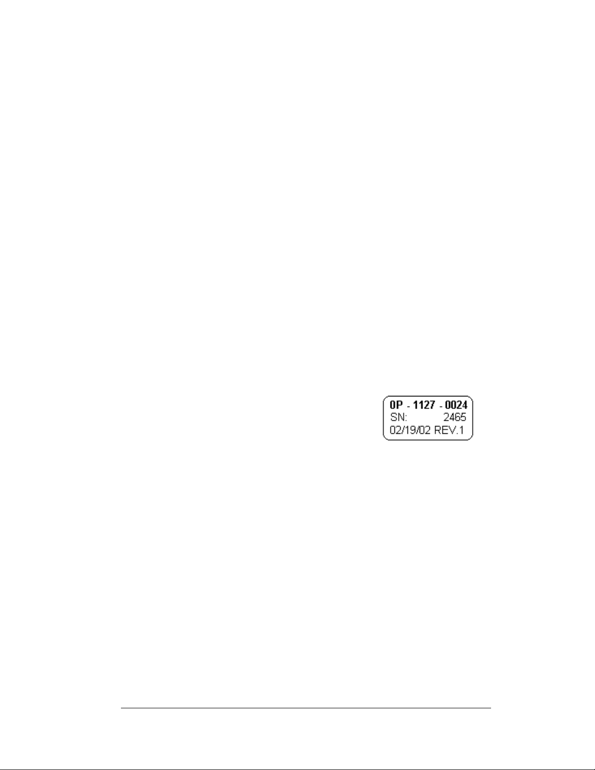
Section 4.13 provides the names and numbers of components that may need to be replaced
during the life of the display. Most display components have a white label that lists the part
number. The component part number is in the following format:
0P-_ _ _ _-_ _ _ _ (circuit board) or 0A-_ _ _ _-_ _ _ _ (multi-component assembly).
Following the Replacement Parts List is the Exchange and Repair and Return Programs
in Section 4.14. Refer to these instructions if any display component needs replacement or
repair.
1.1 Safety Precautions
Important Safeguards:
1. Read an d understand these instructions before installing.
2. Be sure the display and radio enclosures are properly grounded with an
earth ground electrode at the display.
3. Disconn ect power when servicing the display.
4. Do not modify the display structure or attach any panels or coverings to
the display without the written consent of Daktronics, Inc.
1.2 Network Concepts
The concept of using LED displays as a cost effective, high impact method of
communication is rapidly growing throughout many industries and businesses. The
reasons for this growth are many, but the need for additional features and the
complexity of multiple display installations has emerged. Daktronics display systems
have been designed to meet those needs.
1-2
Introduction
Page 9

The common thread to most client requests is a means of programming and controlling a
oup of displays from a central control point. Daktronics responded by developing a
gr
powerful system of interconnecting and controlling displays. Great care has been taken to
design products that will satisfy a wide variety of installations. Some of the design goals
of these systems include the following:
• Easy trans
• Th
e ability to tell a display or group of displays in the network which message
should run
• Th
e ability to determine the status of any display on the network
• Th
e ability to control multiple display technologies on the same network
Tools required for mounting the display depend on the location and size of the display.
For
some installations, it may be possible to purchase pre-terminated telephone cables for
use with the displays.
There are six (6) network systems available: RS232, RS422, modem, fiber, radio and
Eth
ernet. Up to 240 displays can exist on one network.
fer of messages
RS232 Network
RS232 (EIA/TIA-232-E) is a standard communication interface that employs a singleended serial transmission scheme that uses a maximum cable length of 7.6 meters
(approximately 25 Feet). This interface was designed for computer communication at
short distances. The computer used will require an RS232 communication port. Refer to
Section 3 for additional information.
RS422 Network
RS422 (EIA/TIA-422-B) is a standard communication interface that utilizes a differential
balanced transmission scheme that uses a typical maximum cable length of 1.2 km
(approximately 4000 feet). The main advantage to RS422 over RS232 is the longer cable
length that is possible. A signal converter is needed to convert the computer’s RS232
signal to RS422. Refer to Section 3 for additional information.
Modem Network
The modem is a standard communication interface that utilizes standard phone
transmission lines. The phone company assigns each phone line a number that the modem
uses to communicate between computer and display. Each modem network needs to
have a dedicated phone line assigned to it. Refer to Section 3 for additional information.
Fiber Optic Network
A fiber optic network is a standard communication method transmitting light (signal)
through a glass fiber. Fiber optic cable has a maximum length of 600 meters
(approximately 2,000 feet). A signal converter is needed to convert the computer’s
RS232 signal to fiber optic signal; a minimum of two fibers is required. Refer to Section
3 for additional information.
Introduction
1-3
Page 10

Radio Network
The radio network is a standard communication method that uses radio waves at high
frequencies to transmit signal. The Venus
distance of 450 meters (approximately 1500 feet) outdoor and 150 meters
(approximately 500 feet) indoor. A nearly straight line-of-sight path must be
maintained between the Server Radio connected to the computer and the Client
Radio connected to the display. Refer to Section 3 and the Venus 1500 Radio
Manual, ED-13932, for the additional information.
®
1500 Radio network has a maximum
Ethernet Network
Note: The use of a quick connect cable or interconnect wiring between display
controllers will not allow separate control of the second display if the input
signal was Ethernet. Only separately wired primary displays are allowed when
controlled by an Ethernet signal.
1. Th
e Ethernet network that uses fiber optic cable is a standard
communication method transmitting light (signal) through a glass fiber.
When used with the media converter the fiber optic cable has a maximum
length of 2000 meters (approximately 1.2 miles). One media converter is
needed to convert the Ethernet signal from the hub or switch to fiber optic
signal and then a second media converter is located in the display that
converts the fiber signal back to Ethernet. A minimum of two fibers is
required. Refer to Section 3 for additional information.
2. Th
e Ethernet network that uses copper cable is a standard communication
interface that utilizes a local area network (LAN). Utilizing Cat-5/Cat-5E
cable, this transmission scheme has a typical maximum cable length of 100
meters (approximately 330 feet) from an Ethernet hub or switch. The cable
will connect to a network hub and then to the Ethernet surge card in the
display. Refer to Section 3 for more information.
1.3 Sign Overview
Reference Drawings:
Power Specs, AF-3197, RGB LEDs
Component Layout, AF-3190-**x**-89mm
Shop Drawings ........................................................Ref
Daktronics designs and manufactures AF-3197 Galaxy
reliability, easy maintenance, and long life. The pixels have an 89mm
center-to-center spacing and LEDs (light emitting diodes). Each display section has a
m
inimum of 24-inch character height. A light sensor on the front of the first display
is used for automatic dimming of the LEDs based on the ambient light levels.
Refer to D
approximate size, weight, and power requirements for your model of display.
1-4
rawing A-183906, Drawing B-181666, and th e Shop Drawings for the
............................ Drawing A-183906
.................. Drawing B-181666
er to Appendix A
®
displays for performance,
Introduction
Page 11
The following describes the Galaxy
RR
=
Outdoor 89mm Louvered RGB Galaxy Sign
=
Number of Rows High (8, 16, 24, 32, 40 and 48 are available)
AF-3197
®
model numbers: AF-3197-RRCCC-89-RGB
89
=
Number of Columns Long (32, 48, 64, 80, 96, and 112 are
available)
=
89mm center-to-center pixel spacing
=
LED Color (32,000 RGB)
CCC
RGB
A typical sign system consists of a Windows
®
Venus
runs under Windows
1500 software and one or more displays. Venus® 1500 is a software package that
®
98, ME™, NT® 4.0, 2000, or XP Home/Professional operatin g
systems on an IBM-compatible computer. Refer to the Venus 1500 controller manual,
ED13530, for installation and maintenance of the Ve nus 1500 editing station.
The displays are single-face units, which are si
display is called the primary, and if mounted back-to-back with a second display; the
second display is called the echo. If the second display will be mounted at a distance of
more than ten feet from the primary, which is common with the 89mm displays, the quick
connect interconnect cable cannot be used. Signal between controllers will need to be
hardwired.
1.4 Component Identification
The following illustrations and definitions depict some of the more commonly accessed
®
Galaxy
meet customer needs, the actual sign design may vary slightly from the illustrations
below.
This is only a brief overview. Refer to Secti
and troubleshooting various sign components.
Com Port: T
controls the sign through either a 9 or a 25 pin serial connector.
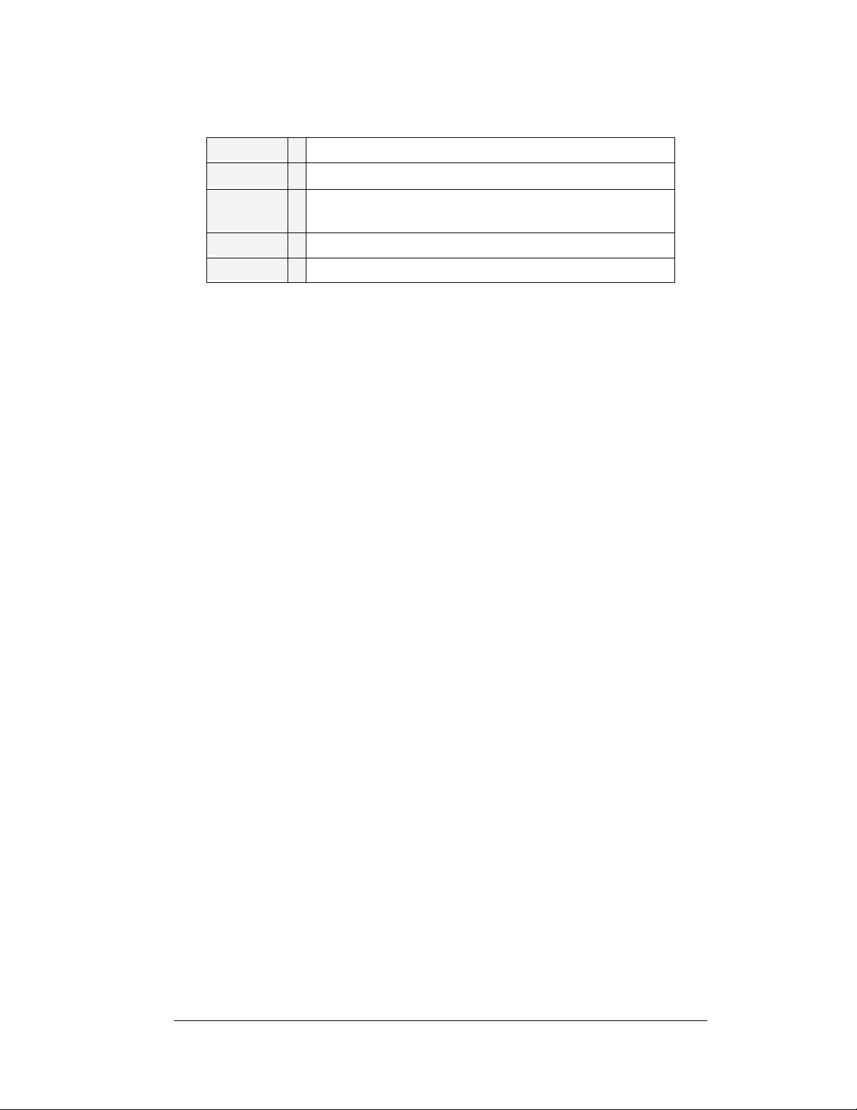
Controller: Th
receives, translates, and activates the signal information from the control computer to the
appropriate pixels on the display accordingly.
sign components. Because Daktronics occasionally alters standard design to
on 4 for detailed information on maintaining
he serial connector on the back of the control computer. The COM port
e display’s controller is the “brains” of the display. The controller
®
based personal computer (PC) running
ngle-sided stand-alone displays. The first
Introduction
1-5
Page 12
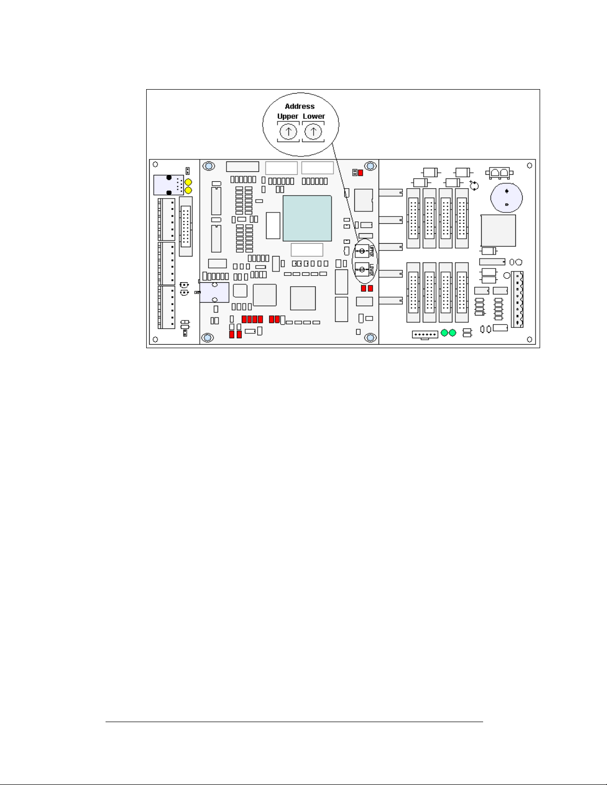
Figure 2: Controller
Driver: Circuit board responsible for switching the intensity levels of the LEDs. The
driver is located inside the driver box and mounts on the back of the module.
Fiber Optic: Technology that uses glass (or plastic) threads (fibers) to transmit data
from the controller to the display. A fiber optic cable consists of a bundle of glass
threads, each of which transmits messages modulated onto light waves.
Galaxy
®
: Daktronics trademarked name for LED monochrome, tri-colored, or RGB
matrix signs.
Latch Access Fastener: Device utilizing a rotating retainer bar to hold the module
firmly to the display frame. There is one latch near the center of the module on the
right side.
LED (light emitting diode): Low energy, high intensity lighting units.
Louver: Black shade positioned horizontally above each pixel row. The louvers
increase the level of contrast on the display face and direct LED light.
Module: 89mm Galaxy
pixel strips, louvers, and a driver. Refer to
®
modules are 8 pixels high by 8 pixels wide. They consist of
Figure 3 for identification of parts.
Network: Consists of multiple signs connected to each other.
Pixel: Cluster of LEDs. The number and color of the LEDs depends on display
application.
1-6
Introduction
Page 13
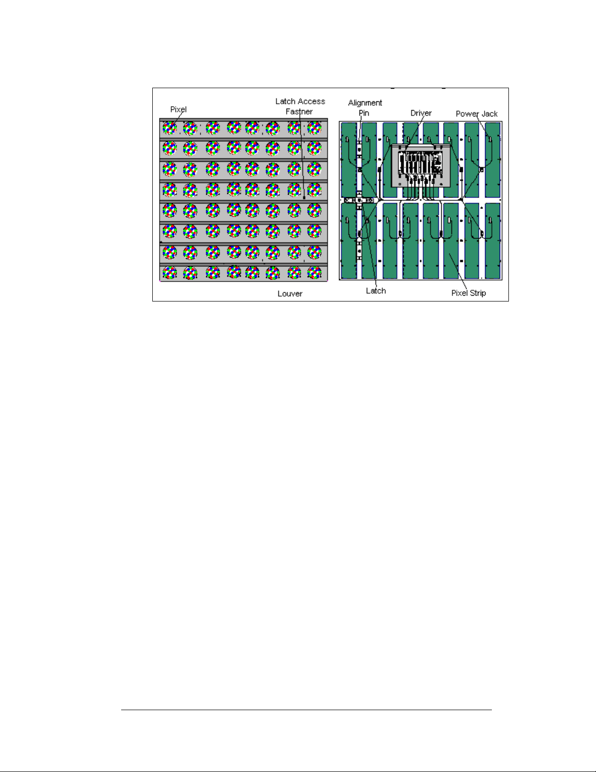
Figure 3: 8x8 Pixel Module (Front and Rear)
Pixel Strip: Four LED pixels mount directly onto a pixel strip. Each pixel strip is
removable from the module. There are 16 pixel strips per module.
Power Supply: Converts AC line voltage from the load center to low DC voltage for
one or more module driver boards.
RS232: RS232 is a standard PC communication type with a maximum cable length
of 25 feet (7.62 meters)
RS422: RS422 is a standard differential communication type with a maximum cable
length of 4000 feet (1.2 kilometers).
Serial Port: An actual serial port is required for direct connections through the Jbox, signal converter or the radio J-box/signal converter from the computer. Certain
USB adaptors create an “actual” serial port and others create “virtual” ports.
Daktronics does not support the use of a USB adaptor. The Venus 1500 software will
not recognize a virtual port.
Sign Address: The sign address is an identification number assigned to each display
of a network. It is set by rotating the hex address switches on the controller. The
control software uses the address to locate and communicate with each display.
Displays that are on the same network cannot have the same address.
Introduction
1-7
Page 14
Signal Converter: The signal converter, shown in
Figure 4, is a Daktronics supplied unit that converts
the data from RS232 to RS422. A similar looking
device is used to convert RS232 to fiber optic signal.
The signal converter is connected to the control PC via
a straight through serial cable.
®
Venus
1500: Daktronics designed, Windows® based
software used to create and edit messages on the
display. Refer to ED-13530 for more information.
1.5 Daktronics Nomenclature
Figure 4: Signal Converter
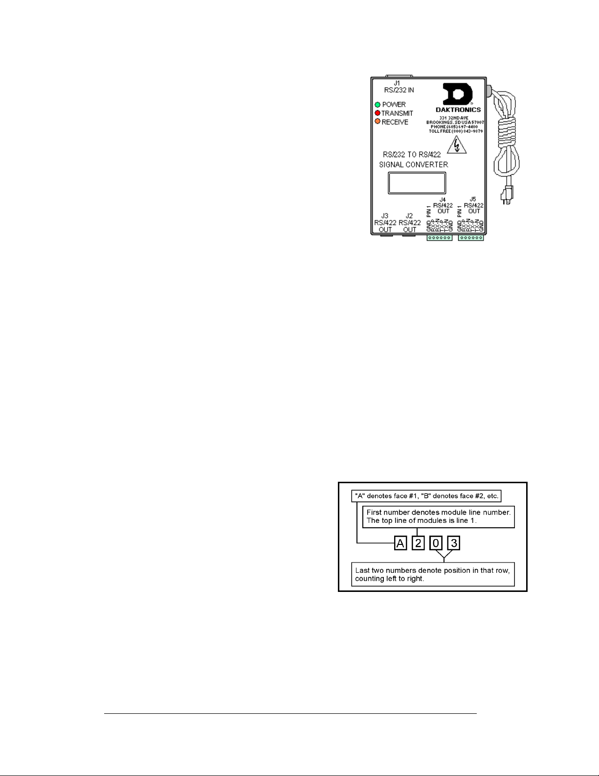
Figure 5: Module Numbering Example – 24x80 Front
To fully understand some Daktronics drawings, such as schematics, it is necessary to
know how those drawings label various components. This information is also useful
when trying to communicate maintenance or troubleshooting efforts.
A module is the building block of the sign.
Each module measures 8 pixels high by 8
pixels wide. By placing modules side-by-side
and on top of one another, Daktronics can
design and build signs of any size. A person
can easily remove individual modules from the
sign if required.
Daktronics numbers modules on a Galaxy
sign.
Figure 6 breaks down the module
numbering method.
Figure 5 illustrates how
®
Figure 6: Module Numbering
1-8
Introduction
Page 15
In addition, various Daktronics drawings may contain the following labeling formats:
• “TB_ _” shows a termination block for power or signal cable.
• “F_ _” denotes a fuse.
• “E_ _” signifies a grounding point.
• “J_ _” stands for a power or signal jack.
• “P_ _” represents a power or signal plug for the opposi t e jack.
Finally, drawings commonly have Daktronics part numbers. You can use those part
numbers when requesting replacement parts from Daktronics Customer Service.
Take note of the following part number formats:
• “0P-_ _ _ _-_ _ _ _” gives the form of an individual circuit board, such as a
module driver.
• “0A-_ _ _ _-_ _ _ _” represents an assembly, such as a circuit board and the
plate or bracket to which it mounts. A collection of circuit boards working
as a single unit may also carry an assembly label.
• “W-_ _ _ _” indicates a wire or cable. Cables may also carry the assembly
numbering format in certain circumstances. This is especially true of ribbon
cables.
• “F-_ _ _ _” signifies a fuse.
Most circuit boards and components within this sign carry a label that lists the part
number of the unit. If the Replacement Parts List in Section 4. 13 does not list a
circuit board or assembly, use the label to order a replacement.
Figure 7 on the right
illustrates a typical label. The part number is in bold.
Figure 7: Typical Label
Introduction
1-9
Page 16

Page 17

Section 2: Mechanical Installation
Note: Daktronics does not guarantee the warranty in situations where the display is not
constantly in a stable environment.
Daktronics engineering staff must approve an
of the display. If you make any modifications, you must submit detailed drawings of the
changes to Daktronics for evaluation and approval, or you may void the warranty.
Daktronics is not responsible for installations or the structural integrity of support
struc
tures done by others. The customer is responsible to ensure a qualified structural
engineer approves the structure and any additional hardware.
2.1 Mechanical Installation Overview
y changes that may affect the weather-tightness
Because every installation site is unique, Daktronics has no single procedure for
mounting Galaxy
or may not be appropriate for your particular installation.
A qualified installer must make all decisions re
display.
Read both the mechanical and electrical installati
before beginning any installation procedures.
®
displays. This section contains general information only and may
2.2 Support Structure Design
Support structure design depends on the mounting methods, display size, and weight.
Since the structure design is critical, only a qualified individual should mount the
display. Display height and wind loading are also critical factors. It is the customer’s
responsibility to ensure that the structure and mounting hardware are adequate.
Daktronics is not responsible for the installations or the structural inte gri t y of
support structures done by others.
The installer is responsible to ensure the mounting
capable of supporting the display and agrees with local codes.
Before beginning the installation proces s, verify the following:
• The mounting structure provides a straight and square frame for the display.
• The mounting structure supports the display without yielding at any
unsupported points after mounting.
• Clearance: 3" of unobstructed space is available below the display for
ventilation. 1¼" of unobstructed space is available above the top of the
display.
Correct any deficiencies b
efore installation.
garding the mounting of this
on sections of this manual
structure and hardware are
Electrical Installation
2-1
Page 18
2.3 Ventilation Requirements
Reference Drawings:
Shop Drawings.........................................................Refer to Appendix A
Fans mounted in the backsheets toward the top of the display allow for ventilation.
Maintain a minimum distance of 3" (7.62 cm) below the display to maintain proper
airflow. Refer to the appropriate Shop Drawing for additional information.
If the display cabinet is completely enclosed:
• Provide 6 square inches of unobstructed ope ni n g per module to ensure
adequate cooling.
• Make allowances to compensate for the percentage of material covering the
openings in the structure.
• For adequate cooling, the cabinet may require forced ventilation. If the
enclosed cabinet must use forced ventilation, it must ventilate at a rate of 10
cubic feet per minute per module (28" x 28" active area).
Failure to comply with these requirements voids the Galaxy
2.4 Lifting the Display
®
display warranty.
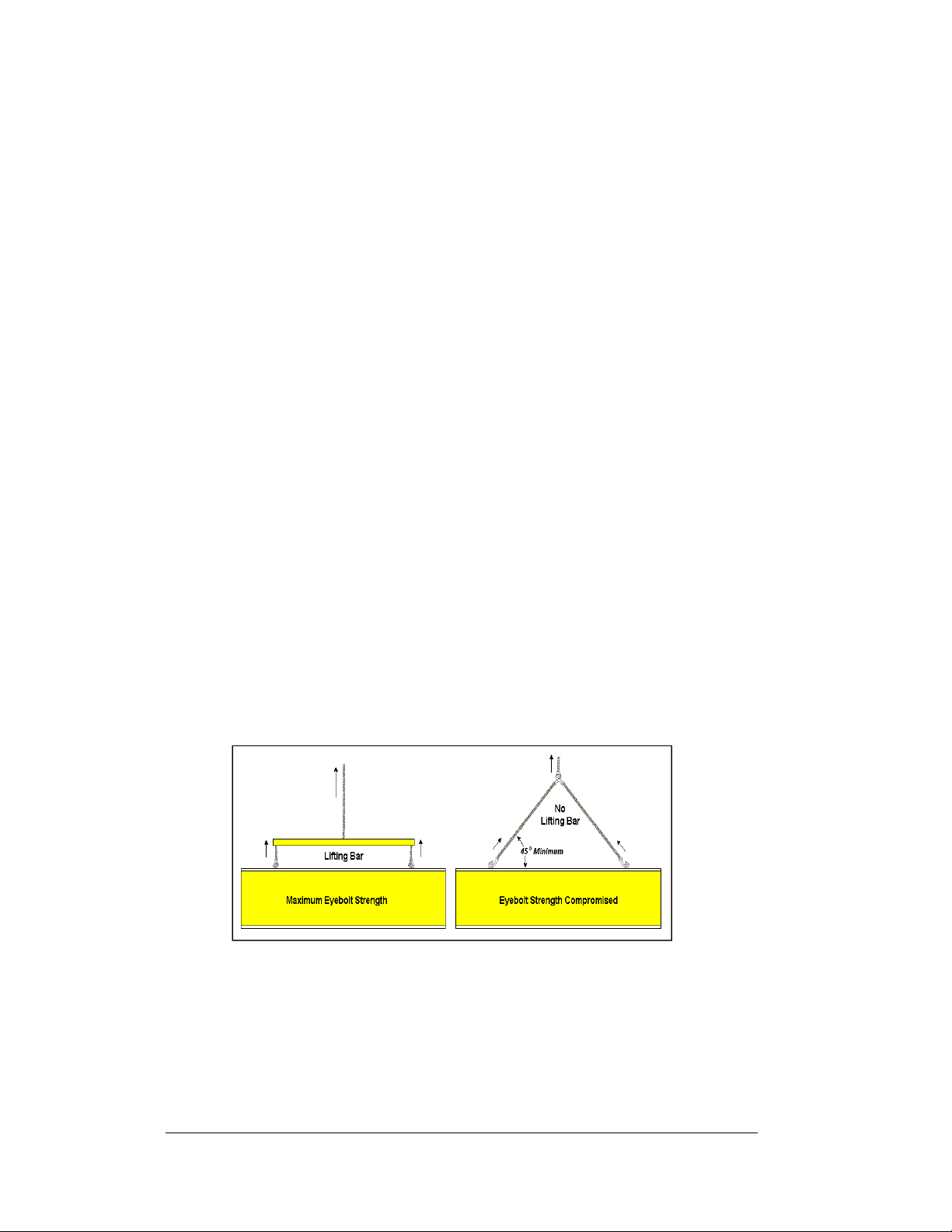
The top of the display has eyebolts to lift the unit. Do not exceed the rated load of
the eyebolts. Refer to the information at the end of this section labeled Eyebolts to
determine the allowable load of the eyebolts shipped with the display.
Figure 8 illustrates both the correct (left example) and the incorrect (right example)
method of lifting a display. Lift the display as shown on the left, with the lifting bar.
Use every lifting point provided.
Figure 8: Lifting the Displays (left; correct) and (right; incorrect)
Do not attempt to permanently support the display by the eyebolts.
If you remove the eyebolts, adequately seal the holes using 13 bolts and sealing
washers, ½ inch in size. Silicone along the threads to ensure water does not enter the
display.
2-2
Electrical Installation
Page 19

2.5 Display Mounting
Reference Drawings:
Assy, Grounding and Fan Harness ............................. Dra
Schematic, AF-3197-8-48x
Block Diagram, Power, AF-3197, 89mm .....................Dra
Shop Drawings......................................................... Ref
The method used to mount displays varies greatly from location to location. For this
reason
, the manual covers only general mounting topics.
The installer is responsible to
codes and standards. The installer is also responsible for the mounting method
and hardware.
Before beginning the installation proces s, verify the following items:
• The mounting structure will provide a straight and square frame for the sign.
Height variation in any four-foot horizontal section may not exceed ¼- inch.
• The mounting structure will not give way at any unsupported points after the
sign is mounted.
The back of the display uses 3x2x
Shop Drawings. These angles assist in mounting the display. Remember to have all
mounted displays inspected by a qualified structural engineer.
The customer must ha
attachment points needed and the wall structure to ensure both meet all nationa l and
local codes. Daktronics recommends using all clip angles as attachment points.
1. Carefu
possible damage cased during shipping.
2. Fol
lowing the guidelines described in Section 2.4, lift the display into
position on the support structure using all provided eyebolts.
3. W
eld or use ½" Grade-5 bolts and hardware to secure the clip angles to the
support structure as shown in Top View in Shop Drawings. Refer to
Section 3 for information on routing power and sig nal .
4. (For Sectional Displays Only): Rem
Using all lift eyes provided, lift the top section over the bottom section.
Align the holes as required for 5/8" hardware. Secure sections using 5/8"
hardware, as shown in the Shop Drawings. Connect power and signal (refer
to Drawings A-175194, A-184111, and B-184326). The sign is then ready
for installation.
5. Upon
completing the installation, carefully inspect the display for any holes
that may allow water to seep into the display. Seal any openings with
silicone. If you remove the eyebolts on the top of the display, plug the holes
with bolts and the rubber sealing washers that you removed with the
eyebolts. Silicone the threads on the bolts.
ve a qualified structural engineer review the number of
lly uncrate the display. Look each side of the display over for
wing A-175194
32x***-89, RGB.................Drawing A-184111
wing B-184326
er to Appendix A
ensure the installation will adequately meet local
3
/8" steel clip angles at the locations shown in the
ove lift eyes from the bottom section.
Electrical Installation
2-3
Page 20

2.6 Optional Temperature Sensor
If you have an optional temperature sensor to be used with your display, see
Appendix C for mounting and signal connections.
2-4
Electrical Installation
Page 21
Eyebolts
Almost every display that leav es D ak tronics is equipped w ith ey ebolts for lifting the display . There are
two standard sizes of eyebolts: ½″ and A″.
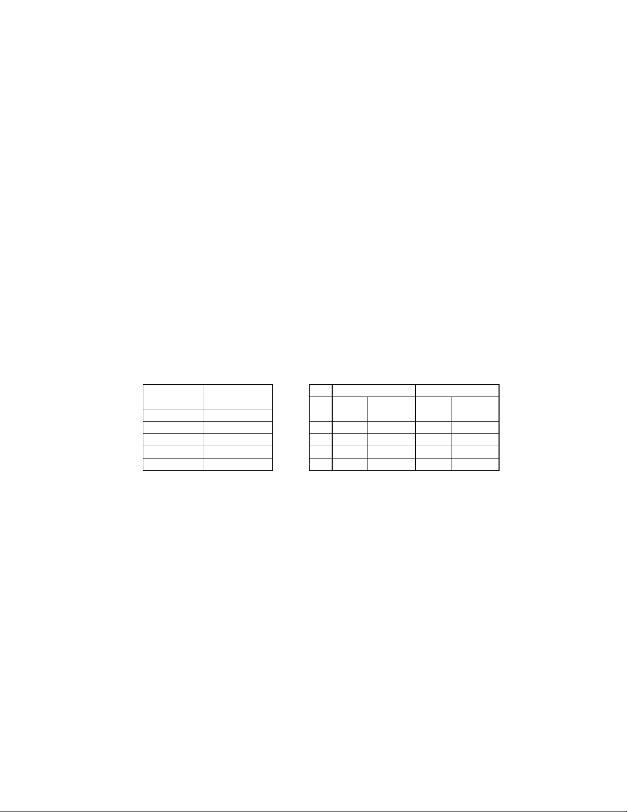
Load Increase Factor: The load increases as the lift angle (θ) decreases. The allowable load on the
eyebolts also decreases with the lift angle due the bending stress on the eyebolts. In sum, the smaller
the angle between the cable and the top of the display, the lighter the sign must be to safely lift it. Do
NOT attempt to lift the display when the lift angle is less than 30 degrees.
Horizontal Load Angle
Angle Factor (L/H)
90 1.00
60 1.155 90 2600 2600 4000 4000
50 1.305 60 1500 1299 3300 2858
45 1.414 45 650 460 1000 707
30 2.00 30 520 260 800 400
θθθθ
½”
Line Weight/ Line Weight/
Load Anchor Load Anchor
A
A”
AA
ED7244 Copyright 1996-2001
Rev. 4 – 14 March 2001 Daktronics, Inc.
Page 22
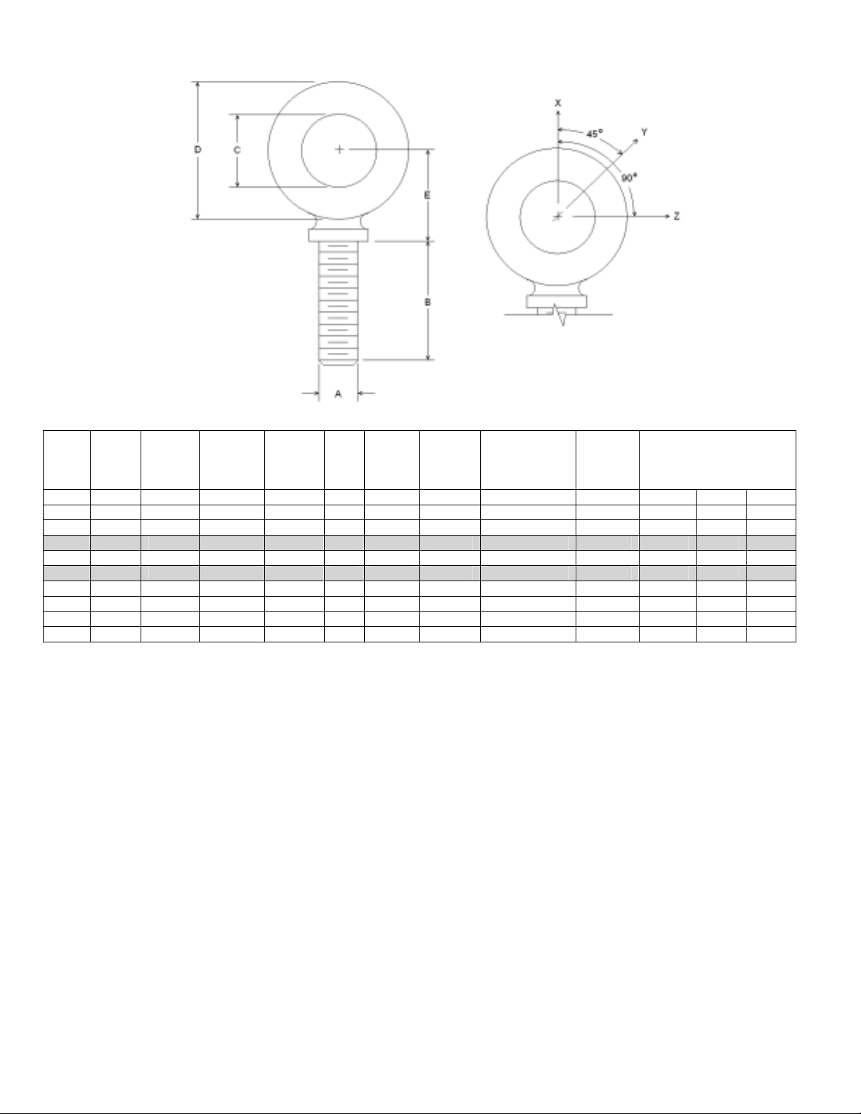
Min.
A B C D E No.
Wx Wy Wz
1/4 1 3/4 1-3/16 25/32 21 600 2,000 Blank 1/4-20 7/8 400 100 80
3/8 1-1/4 1 1-21/32 1-3/16 23 2,100 5,000 Blank 3/8-16 1-1/8 1,400 350 250
1/2 1-1/2 1-3/16 2-1/16 1-13/32 25 3,900 9,200 Blank 1/2-13 1-11/32 2,600 650 520
9/16 1-5/8 1-9/32 2-13/16 1-17/32 26 4,500 11,830 Blank 9/16-12 1-3/8 3,000 750 600
5/8 1-3/4 1-3/8 2-1/2 1-11/16 27 6,000 14,700 Blank 5/8-11 1-9/16 4,000 1,000 800
3/4 2 1-1/2 2-13/16 1-13/16 28 9,000 21,700 Blank 3/4-10 1-5/8 6,000 1,500 1,200
7/8 2-1/4 1-11/16 3-1/4 2-1/16 29 10,000 30,000 Blank 7/8-9 1-13/16 6,600 1,670 1,330
1 2-1/2 1-13/16 3-9/16 2-5/16 30 12,000 39,400 Blank 1-8 2-1/16 8,000 2,000 1,600
1-1/2 3-1/2 2-9/16 5-1/2 3-5/32 34 27,000 91,300 Blank 1-1/2-6 3 17,800 4,500 3,600
Proof
Load
(lbs.)
Min.
Break
Load
(lbs.)
Stocked
Min.
Eff.
Thrd.
Length
Line Loads
A. Do not use eyebolts on angular lifts unless absolutely necessary. For angular lifts, the shoulder pattern
eyebolt is preferred.
B. Load should always be applied to eyebolts in the plane of the eye, not at some angle to this plane.
C. Shoulder eyebolts must be properly seated (should bear firmly against the mating part), otherwise the
working loads must be reduced to those indicated for regular eyebolts. A washer or spacer may be
required to put the plane of the eye in the direction of the load when the shoulder is seated.
D. No load greater than the safe working load listed in the data table should be used.
E. To obtain the greatest strength from the eyebolt, it must fit reasonably tight in its mounting hole to prevent
accidental unscrewing due to twist of cable.
F. Eyebolts should never be painted or otherwise coated when used for lifting. Such coatings may cover
potential flaws in the eyebolt.
G. To attain the safe working loads listed for regular eyebolts, 90% of the thread length must be engaged.
Copyright 1996-2001 ED-7244
Daktronics, Inc. Rev. 4 – 14 March 2001
Page 23
Section 3: Electrical Installation
Only a qualified individual should terminate the power and signal cable within this Daktronics
display.
The Daktronics engineering staff must approve any changes made to the display. Before
altering the display, submit detailed drawings for the proposed modifications to the
Daktronics engineering staff for evaluation and approval or you will render the warranty null
and void.
3.1 Common Connectors in the Display
The power and signal connections in the displays use many different
types of connectors. Take special care when disengaging any connector,
as not to damage the connector, the cable, or the circuit board. When
pulling a connector plug from a jack, do not pull on the wire or cable;
pull on the jack itself. Pulling on the wires may damage the connector.
The following information presents some common connectors
encountered during sign installation and maintenance:
1. Ribbon Cable Connectors:
Figure 9 illustrates a typical ribbon connector. To disconnect the
ribbon cable, push the plastic clips on the sides to unlock and
remove the jack.
Before replacing a ribbon cable connector, spray it with DeoxIT
contact cleaner to remove any foreign matter that may cause signal
problems. In addition, apply a generous amount of CaiLube
™
protector paste to the plug before inserting it into the jack. This
paste protects both the plug and the jack from corrosion.
2. Termination Blocks:
Termination blocks connect internal power and signal wires to
wires of the same type coming into the sign from an external
source. Most signal wires come with forked connectors crimped to
the ends of the wire. Power wires need to have one-half inch of
insulation stripped from the end of the wire prior to termination.
Tighten all screws firmly to ensure a good electrical connection.
Refer to
Figure 10.
3. Phoenix
™
-Style Connectors:
Phoenix-style connectors, usually green, allow for signal
termination on circuit boards. Refer to
Figure 11. Strip one-quarter
inch of insulation from the wire prior to termination. To remove a
wire, turn the above screw counter-clockwise to loosen the
connectors grip on the wire. To insert a wire, push the bare wire into the
connector and turn the above screw clockwise to lock the wire into place.
Figure 9: Ribbon
Cable Connector
™
Figure 10: Termination
Block
Figure 11: Phoenix
Connector
Electrical Installation
3-1
Page 24
4. Mate-n-Lok
™
Connectors:
The white Mate-n-Lok connectors found in the signs come in
a variety of sizes.
Figure 12 illustrates a five-pin Mate-n-Lok
connector. To remove the plug from the jack, squeeze the
plastic locking clasps on the side of the plug and pull it from
the jack.
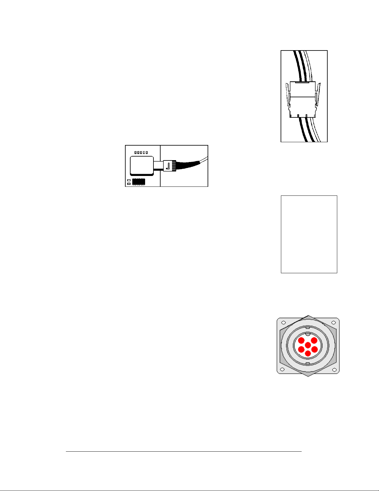
5. Fiber Optic Connectors:
A fiber optic cable has a “twist-on” connector at each end.
To remove the fiber plug, push it toward the board and twist
it counter-clockwise until you can pull the plug from the
jack.
Figure 13 shows this connector.
Figure 13: Fiber Optic Cable
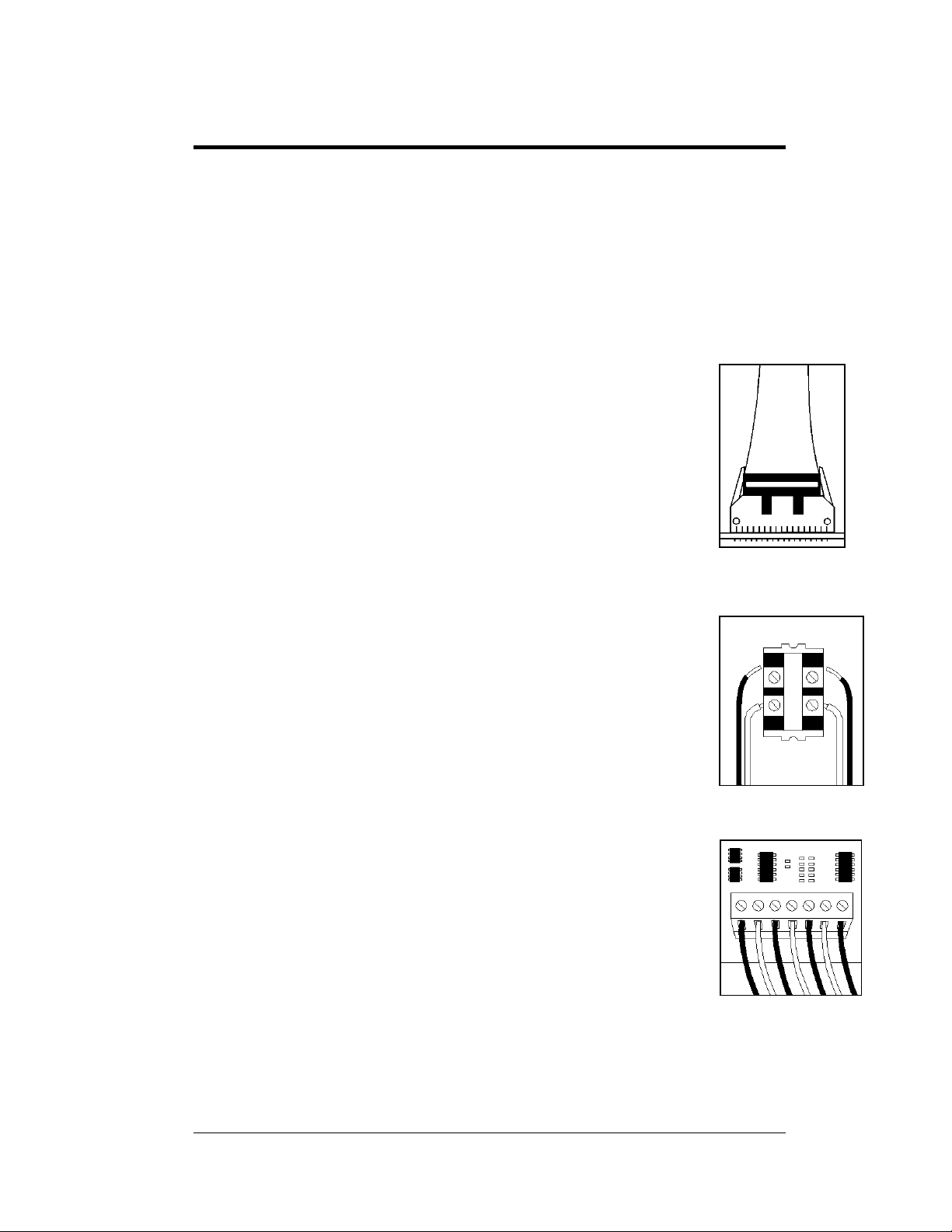
6. Phone Jacks (RJ11 Connectors):
RJ connectors, as seen in
Figure 14, are similar to the telephone
connectors found in homes. In order to remove this plug from the
jack, depress the small clip on the underside of the plug.
Before replacing an RJ connector, spray it with DeoxIT
™
contact
cleaner to remove any foreign matter that may cause signal problems.
In addition, apply a generous amount of CaiLube
™
protector paste to
the plug before inserting it into the jack. This paste will protect both
the plug and the jack from corrosion.
7. Quick Connect Jack:
The display uses quick connect jacks for the connection of the signal
termination enclosure, the temperature sensor and possible
connection to an echo display. There are three input and one output
quick connect jacks located on the back of the primary display, and
when not used the attached dust cover should be kept closed.
To attach the cable to a jack, make sure to line up the plug to match
the jack, push the plug in then turn the outer collar to lock in place.
Figure 15 illustrates the 6-pin quick connect jack.
Figure 12: Mate-n-
Loc Connector
Figure 14: RJ11
Connector
Figure 15: RS232/6-pin
Quick Connect Jack
3-2
Electrical Installation
Page 25

3.2 Control Cable Requirements
RS232
This cable is a 2-conductor shielded cable used to transmit an RS232 signal
(Daktronics part number W-1117). This shielded cable should not be subjected to
mechanical flexing after installation. This cable is not for direct burial and should be
routed in a dedicated, grounded, metallic conduit at the base of the display structure.
This cable has a maximum length of 25 feet (approximately 7.6 meters).
RS422
This cable is a 4-conductor shielded cable used to transmit an RS422 signal
(Daktronics part number W-1234, Manhattan number M4473.) This shielded cable
consists of unpaired wires. They should not be subjected to mechanical flexing after
installation. This cable is not for direct burial and should have one of the following
routings:
• In d
• Insi
With interface signals (such as power conducto
foot separation is required. The maximum length of an RS422 signal cable is 4,000
feet (approximately 1.22 km).
edicated metallic conduit
de buildings-if cable is not in conduit, keep away from interface signals
rs, intercom, etc.), typically a two-
Modem
The modem option will use standard telephone cable routed through conduit. The
phone cable and power cannot be routed in the same conduit. The local
telephone company will need to assist in this installation. Ask the telephone
company which color is used for the TIP wire and which for the RING wire for
signal hook up to the display.
Note: T
system.
he telephone line must be a dedicated line and not run through a switchboard
Fiber Optic
This cable is a 4-fiber cable (Daktronics part number W-1376). Two fibers are used
for display communications and the other two are saved for spares. The cable may be
either direct burial or routed in conduit, but should not be subjected to mechanical
flexing. The maximum length of a fiber optic cable is 2,000 feet (approximately 600
meters) from the signal converter to the fiber optic board in the display.
Electrical Installation
3-3
Page 26
Radio
The server radio connected to the J-box requires an 18-gauge, six-conductor shielded
cable (Daktronics part number W-1370). Four-conductors will be used for the signal
and two for power. These wires need to be in conduit when exposed to outdoor
conditions to the server radio. The maximum distance from the RS422 J-box to the
server radio is 1000 feet (approximat e l y 330 me t ers).
The client radio at the display comes with a 25 foot quick connect cable that is rated
for outdoor use and does not need to be in conduit. Any excess cable shoul d be
secured to protect it from weather and vandalism.
Ethernet
Note: The use of a quick connect inter-connect cable or separately wired cable is not
allowed between two of more displays if the input to the first display is Ethernet.
Fiber Ethernet
This cable is a 4-fiber cable (Daktronics part number W-1376). Two fibers are used
for display communications and the other two are saved for spares. The cable may be
either direct burial or in conduit, but it should not be subjected to mechanical
flexing. The maximum length of the fiber optic cable from one media converter
connected to the network and the second media converter in the display is 1.2 miles
(approximately 2000 meters).
Ethernet
This cable is an 8-conductor network cable (Daktronics part number W-1467 Cat-5,
or W-1384 Cat-5E). The cable should not be subjected to mechanical flexing after
installation. This cable is not for direct burial and should have one of the following
routings:
• In dedicated metallic conduit, separate from the power.
• Inside buildings-if cable is not in conduit, keep away from interface signals
With interference signal, such as power conductors, intercom, etc., typically a twofoot separation is required. The maximum length of an Ethernet signal cable is 330
feet (approximately 100 meters) from the network hub or switch to the surge board
in the display.
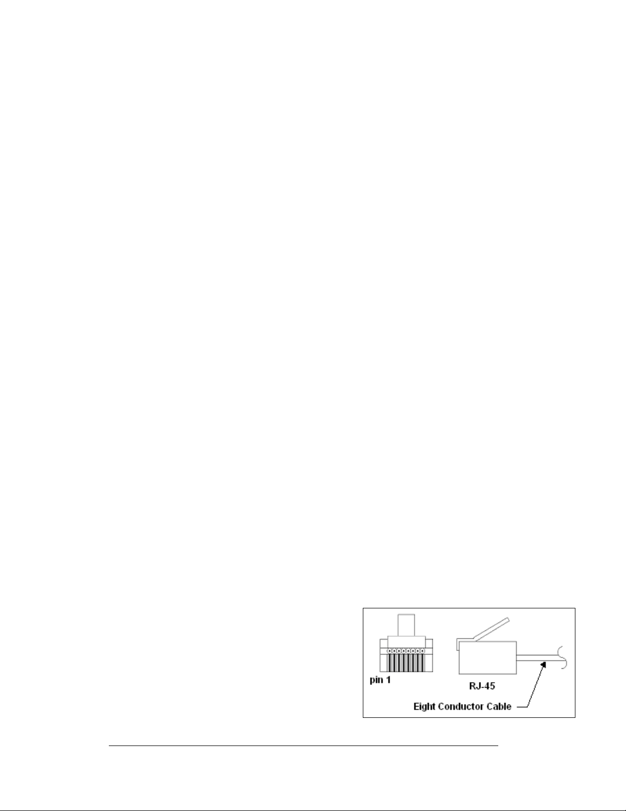
3.3 RJ Connector Cables
RJ connectors are of two basic types. They consist
of the RJ11 connector that uses a six-conductor
cable, and the RJ45 that uses an 8-conductor
cable. This type of connector can be found on
many telephones and LANs.
Both the RJ11 and RJ45 cables used inside the
display are pinned as straight through cables.
Exterior cables used for a network are often
Figure 16: 6-Conductor RJ11 Connector and Cable
3-4
Electrical Installation
Page 27
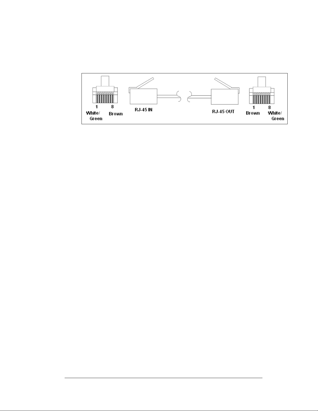
flipped cables. This type of cable, as shown in
image of the other end. When installing a network, to ensure correct cabling, always
install the cable from the output jack of one display to the input jack of the next
display.
Figure 17: Flipped Cable with RJ Connectors
3.4 Conduit
Reference Drawings:
Shop Drawings......................................................... Refer to Appendix A
Daktronics does not include the conduit. Refer to Shop Dra w i ngs for approximate
locations of power and signal conduit. You must use separate conduit to route:
• Power
• Signal IN wires
• Signal OUT wires (if another sign requires si gnal)
Locate the conduit holes at the bottom right (rear view) of the back of the display
(refer to Shop Drawings).
Punch or drill out the desired conduit openings. Be careful not to damage any
internal components. Attach the conduit, and then route the power and signal cables.
For displays with more than one face, signal and temperature sensor wiring between
displays can route through the same conduit.
Figure 17, has one end that is a mirror
Electrical Installation
3-5
Page 28

3.5 Preparing for Power/Signal Connection
Reference Drawings:
Shop Drawings.........................................................Refer to Appendix A
If the display needs openings for the power and sig nal, p unch out the knockouts in
the lower right corner from the rear. Refer to Shop Drawings for more information.
1. With a 7/32" nutdriver, apply
pressure to latch and turn it a
quarter-turn counter-clockwise. The
module door will swing open to the
left.
2. Route power to the display through
a fused disconnect switch capable of
opening all ungrounded po w e r
conductors. Locate this disconnect
within the line of sight of any
personnel performing mai nt enance
on the display. If the disconnect is
located out of sight of the display, it
must be capable of being locked in
the open position.
3. Power conductors from the
disconnect to the display must route through conduit in agreement with
local codes.
4. You may also route the signal cable from the control computer to the sign at
this time. Run the power and signal cables in separate conduit.
Figure 18: Opening the Display
3.6 Power
Reference Drawings:
Power Specs, AF-3197, RGB LEDs............................ Drawing A-183906
Schematic, AF-3197-8-48x32x***-89, RGB................. Drawing A-184111
Layout, Pnl Bd, 8-48x32-112, 89mm, 1 Phase ........... Drawing A-184316
Layout, Pnl Bd, 8-48x32-112, 89mm, 3 Phase ........... Drawing A-184321
Refer to Drawing A-183906 for voltage and current requirements for your display
size. Each uses a 120/240VAC single-phase or 120/208 three-phase power source.
Do not connect the displays to any voltage other than what is listed on the
Daktronics product label.
Proper power installation is imperative for proper display operation. The following
sub-sections give details of display power installation. Electrical installations must
be performed by qualified personnel. Unqualified personnel should not attempt to
install the electrical equipment. Serious danger to equipment and personnel could
occur if equipment is improperly installed.
3-6
Electrical Installation
Page 29
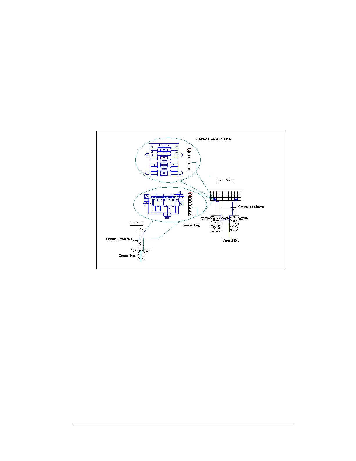
Grounding
Displays must be grounded according to the provisions outlined in Article 250 of the
National Electrical Code
less. Verification of ground resistance can be performed by the electrical contractor
who is performing the electrical installation. Daktronics Sales and Service personnel
can also perform this service.
The display system must be connected to earth-ground. Proper grounding is
necessary for reliable equipment operation. It also protects the equipment from
damaging electrical disturbances and lightning. The display must be properly
grounded or the warranty will be void.
®
. Daktronics requires a resistance to ground of 10 ohm s or
Figure 19: Display Grounding
A minimum of one grounding electrode must be installed for each display face. The
grounding electrode is typically one grounding rod for each display face. Other
grounding electrodes as described in Article 250 of the National Electric Code may
be used. Daktronics requires that the resistance to ground be 10 ohms or less. If the
resistance to ground is higher than 10 ohms, it will be necessary to install additional
grounding electrodes to reduce the resistance. The grounding electrode should be
installed within 25 feet of the base of the display. The grounding electrode must be
connected to the ground terminal in the display panel board.
This grounding electrode must be installed in addition to the equipment-grounding
conductor that should be part of the power installation. The material of an earthground electrode differs from region to region and from conditions present at the
site. The support structure of the display cannot be used as an earth ground electrode.
The support is generally embedded in concrete, and if in earth, the steel is either
primed or it corrodes, making it a poor ground. The grounding system and grounding
electrodes must be installed according to Article 250 of the National Electrical Code
and any applicable local codes.
Electrical Installation
3-7
Page 30

Power Installation
There are two considerations for power installation: installation with ground and
neutral conductors provided and installation with only a neutral conductor provided.
For these displays, installation with ground and neutral conductors provided is used.
Installation with Ground and Neutral Conducto s Provided
For this type of installation, the power cable must contain an isolated earth-ground
conductor. Under this circumstance, do not connect neutral to ground at the
disconnect or at the display. This would violate electrical codes and void the
warranty. Use a disconnect so that all hot lines and neutral can be disconnected. The
National Electrical Code requires the use of a lockable power disconnect within sight
of or at the display.
3.7 Main Disconnect
The National Electrical Code requires the use of a lockable power disconnect near
the display. Provide a lockable disconnect switch (knife switch) at the display
location so that all power lines can be completely disconnected. Use a 3-conductor
disconnect to disconnect both the hot lines and the neutral. Mount the main
disconnect at or near the point of power supply connection to the display. Provide a
main disconnect for each supply circuit to the display.
You must locate the means of d
or outline lighting that it controls. This requirement provides protection by enabling
a worker to keep the disconnecting means within view while working on the d isplay.
Exception:
locked in the open position elsewhere.
You may locate the disconnecting means that are capable of being
r
isconnection in a direct line-of-sight from the display
3-8
Electrical Installation
Page 31
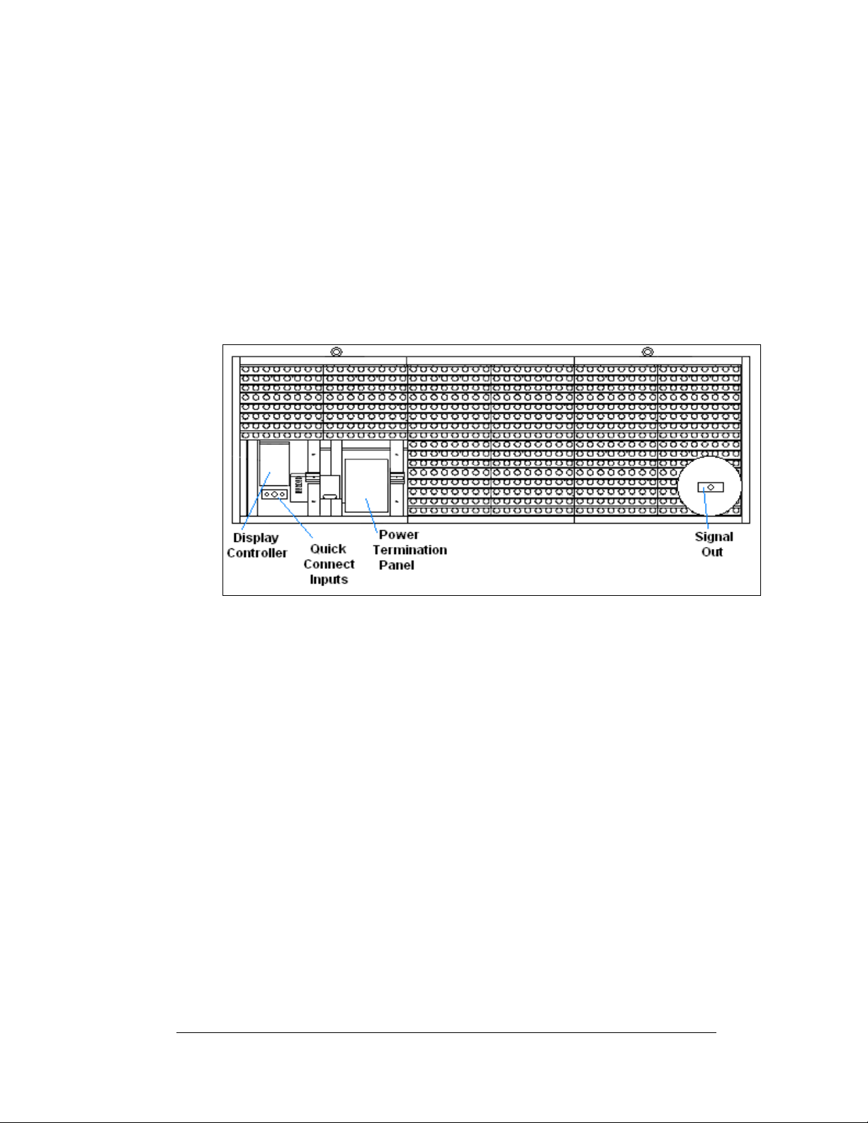
3.8 Signal Termination from Computer to Sign
Note: The AF-3197 is designed for quicker con necti o n t o ot her displays and other
additional equipment. Connection of the control computer to the first d isplay needs
to be wired to the surge suppressor, modem, or fiber optic board in the display.
Depending on the communication type ordered the following cables may be provided
with the display:
1. Interconnect cable from primary to echo, length 10 feet
2. Temperature sensor with quick connect cable, length 10 feet
3. Client radio with quick connect cable, length 25 feet
Figure 20: Signal Termination Locations
RS232
Reference Drawings:
System Riser Diagram, RS232....................................Drawing A-174341
Schem, Sig Wiring, Internal, W/quick Connect PCB....Drawing B-177662
Cntrlr; Galaxy, 8 Conn, J1087......................................Drawing B-177838
A display that is controlled using RS232 requires the use of a J-box within 25 feet of
the display. From the J-box to the display, the signal will be wired directly to the
controller inside the display. The cable from the J-box to the display must be routed
though conduit. Do not run signal and display power through the same conduit.
1. Terminate one end at the J-box and the other end of the wire to the 6-
position terminal block on the controller labeled “RS232 IN” (A31-TB1).
2.
Figure 22 and Drawing B-177662 shows the terminal block wiring.
Drawing B-177838 shows the controller.
3. The con trolling laptop computer connects to the J-box through the DB9 to
DB25 serial cable (W-1249) (refer to Drawing A-174341).
Electrical Installation
3-9
Page 32
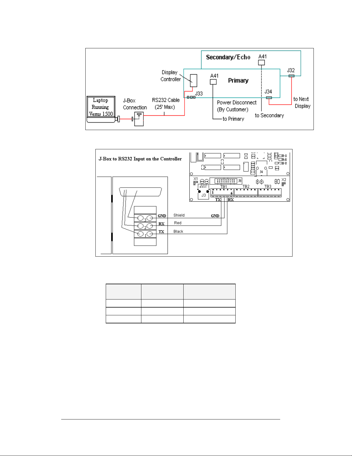
Figure 21: RS232 Display Layout
Figure 22: RS232 Controller Board
J-Box to Controller Board
J-Box
Pin 1 (TX-P) Black Pin 5 (RX-1)
Pin 2 (RX-P) Clear/Red Pin 3 (TX-1)
Pin 3 (GND) Shield Pin 4 (GND-N)
Field Cabling
Controller Board
TB1 (RS232 In)
3-10
Electrical Installation
Page 33
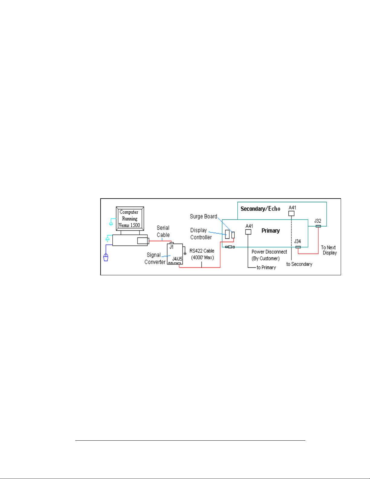
RS422
Reference Drawings:
System Riser Diagram, RS422....................................Drawing A-174135
Schem, Sig Wiring, Internal W/QC PCB......................Drawing B-177662
A display that is controlled using RS422 requires the use of signal converter
(0A-1127-0255) at the computer. From the signal converter, cable is run to the surge
board assembly in the display. The cable from the signal converter to the display
must be routed though conduit. Do not run signal and display power through the
same conduit. Refer to
1. Wh en connecting to the surge card (0P-1146-0031) in the display, terminate
one end at signal converter (J4 or J5) and the other end of the wire to the 6position terminal block on the surge board assembly labeled “RS422 IN”
(TB1).
2.
Figure 24 and Drawing B-177662 shows the terminal block wiring. The
terminal block wiring is pinned one-to-one.
3. The computer connects to the signal converter through a DB9 to DB25
serial cable (W-1249).
Figure 23 and Drawing A-174135 for system layout.
Figure 23: RS422 Display Layout
Electrical Installation
3-11
Page 34
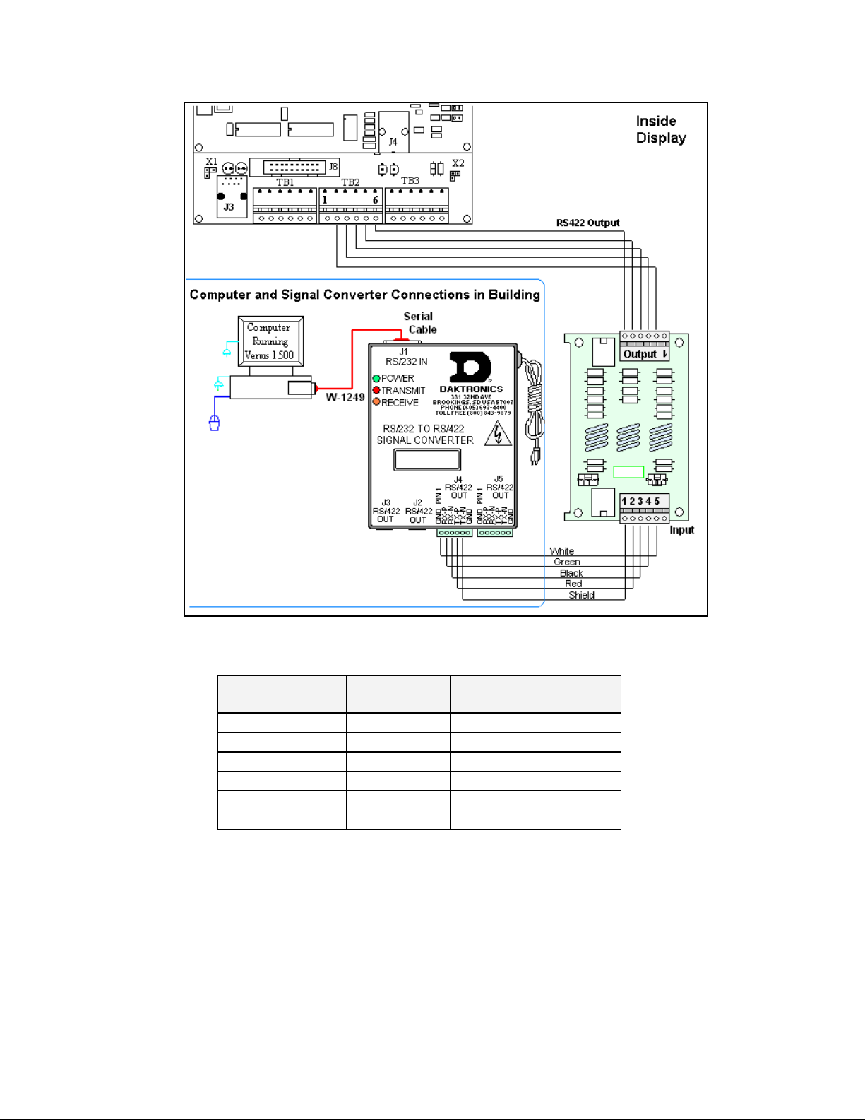
Figure 24: Signal Converter to Surge Board Connection
Signal Converter to Controller Board
Signal Converter
(J4/J5)
Pin 1 (GND) Shield Pin 1 (A GND)
Pin 2 (RX-P) Red Pin 2 (D1OUT-P)
Pin 3 (RX-N) Black Pin 3 (D1OUT-N)
Pin 4 (TX-P) Green Pin 4 (D1IN-P)
Pin 5 (TX-N) W hite Pin 5 (D1IN-N)
Pin 6 (GND) Pin 6 (A GND)
Field Cabling
Surge Board Assembly
TB1 (RS422 In)
3-12
Electrical Installation
Page 35
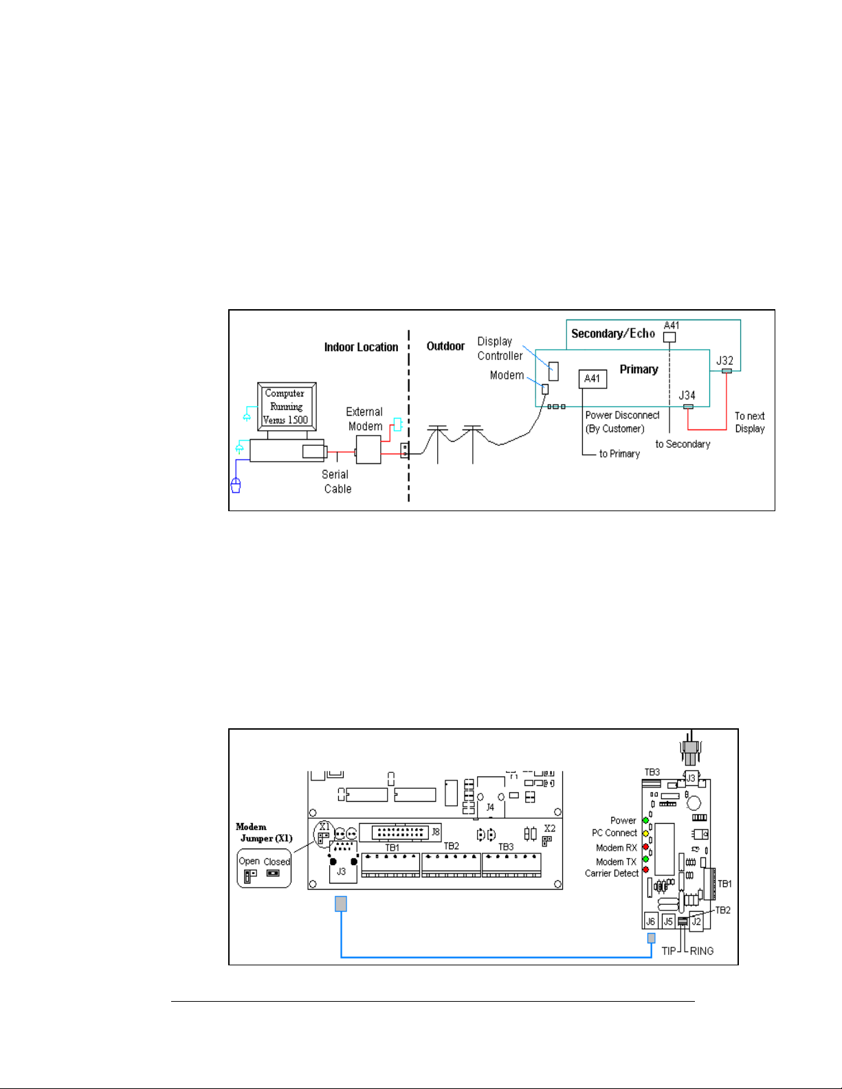
Modem
Reference Drawings:
System Riser Diagram, Modem...................................Drawing A-174342
Schem, Sig Wiring, Internal, W/QC PCB.....................Drawing B-177662
A display that is controlled using a modem requires the use of an internal or external
modem at the computer. The local phone company must provide a dedicated phone
line to the display and identify which color wire is used for “Tip” and which color
for “Ring”. The phone cable must be routed though conduit. Do not run phone line
and display power through the same conduit. Refer to
174342 for system layout.
Figure 25: Modem Display Layout
1. When connecting to the modem in the display, terminate the phone line to
TB2 on the display modem. If the phone company provided a phone
termination box in the display a straight phone cable can be connected from
the box to the J5 Phone IN on the modem board in the display.
2.
Figure 26 and Drawing B-177662 shows the terminal block wiring.
3. A second cable (0A-1229-0054) transfers data from J6 on the modem (0P-
1146-0003) to J3 (RS232 IN) on the contr ol l e r.
4. X1 on the controller should to be closed for the controller to recognize on
bootup that a modem is being used with the display.
Figure 25 and Drawing A-
Figure 26: Modem Signal Termination Location
Electrical Installation
3-13
Page 36
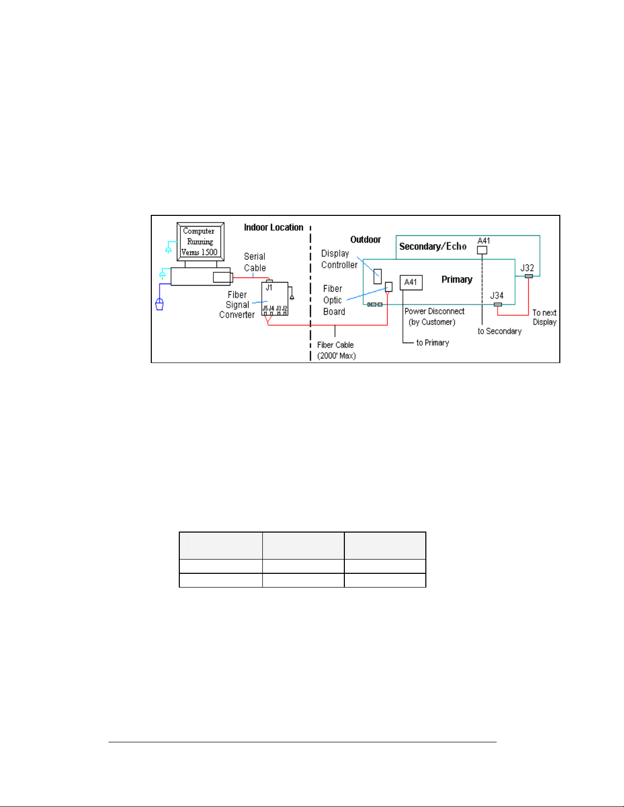
Fiber Optic
Reference Drawings:
System Riser Diagram, Fiber ...................................... Drawing A-174344
Schem, Sig Wiring, Internal, W/QC PCB..................... Drawing B-177662
When using fiber cable, the cable will connect directly from the signal converter to
the fiber optic board in the display. Refer to
the system layout.
Figure 27: Fiber Display Layout
1. Connect the two fibers at the signal converter (0A-1127-0256) and the other
two at the fiber optic board (J4/J5) (0P-1146-0024) in the display. Always
remember to connect TX to RX and RX to TX. (Either pair of fiber outputs
on the signal converter can be used, but only the left pair of inputs on the
fiber optic board in the display.)
2. Refer to
Figure 28 and B-177662 for cabling in the display.
3. A 8-conductor cable with RJ45 connectors ( 0A-1229-0054) then relays the
signal from J7 on the fiber optic board to J3 (RS232 IN) on the controller
4. The computer connects to the signal converter through a DB9 to DB25
serial cable (W-1249).
Signal Converter
to Fiber Board
Signal
Field Cabling Fiber Optic
Converter
J2 (TX1) (Color varies) J5 (RX)
J3 (RX1) (Color varies) J4 (TX)
Figure 27 and Drawing A-174344 for
Board
3-14
Electrical Installation
Page 37
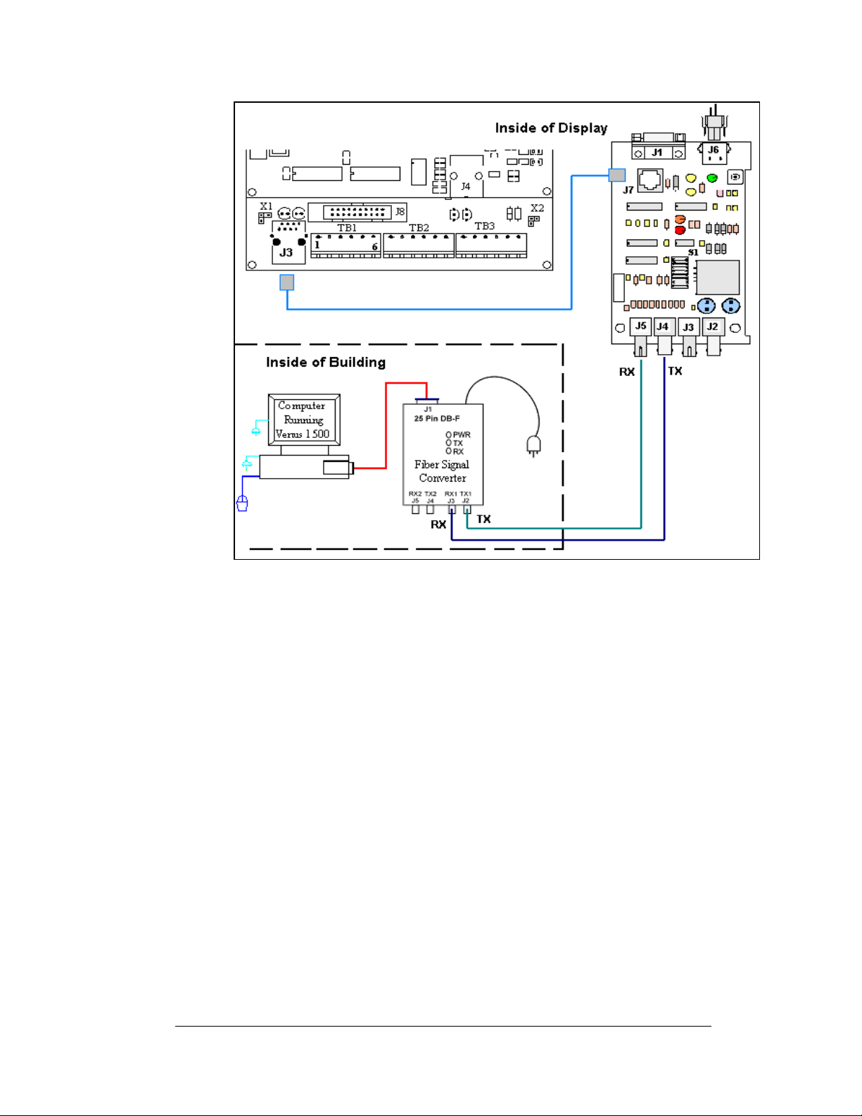
Figure 28: Fiber Signal Connections
Venus® 1500 Radio Client
Reference Drawings:
System Riser, QC Outdoor Radio, V1500...................Drawing A-185359
Schem, Sig Wiring, Internal, W/Q CPCB.....................Drawing B-177662
A display that is controlled using a radio requires a server radio connected to the
control computer, and a client radio connected to the display using a pre-terminated
cable. The following conditions are required for good radio operation:
1. The radios must be within line-of-site of each other.
2. The total distance between the outdoor radios should not exceed 1500 feet.
3. The an tennas for the server and client radio should be in a parallel position
with each other.
Refer to Drawing A-185359 and
Figure 29 for system layout.
Electrical Installation
3-15
Page 38
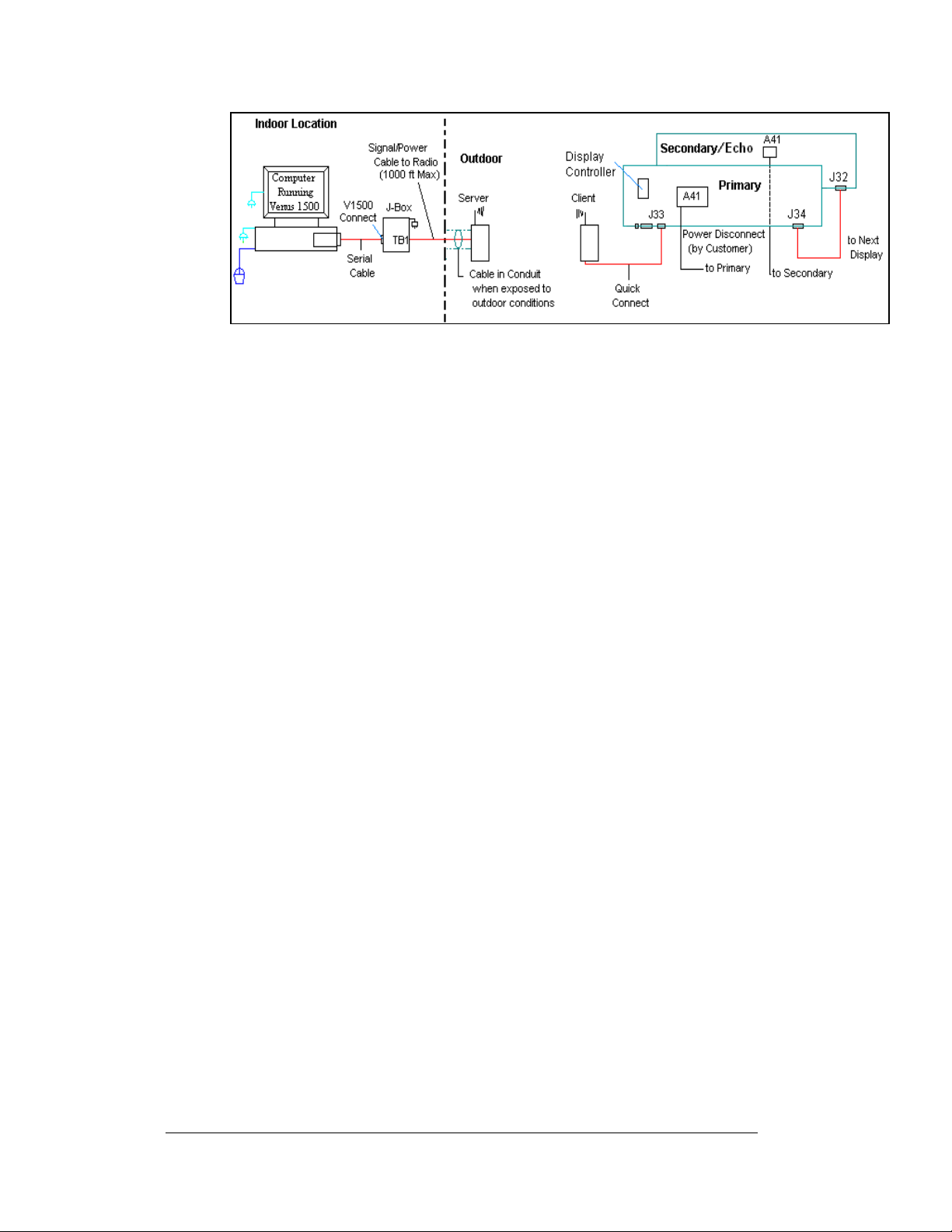
Figure 29: Radio Display Controller
1. The computer connects to the J-box/signal converter (0A-11279-0161) at
2. Use an 18 AWG, 6-conductor, cable to connect from the J-box/signal
3. The client radio (0A-1146-0078) is provided with 25 feet of weather
4. One end of the cable is pre-terminated to TB2 inside the radio enclosure,
the connector labeled “V1500 PC Connect” using a DB9M to DB9F serial
cable (W-1267).
converter to the server radio (0A-1146-0079) mounted on the outside of the
building. The cable is pinned one-to-one. (Additional drawings for the
server connections are in the Venus 1500 Radio Manual, ED13932.)
resistant pre-terminated cable. The cable will be terminated to the display
with the quick connect plug to the top, red jack, labeled J33, on the display.
Refer to
Figure 30 for the quick connect termination point.
and a quick connect plug is terminated at the other end of the cable. Note:
Secure any additional cable for protection from weather or vandalism.
3-16
Figure 30: Client Radio connected to Display
Electrical Installation
Page 39
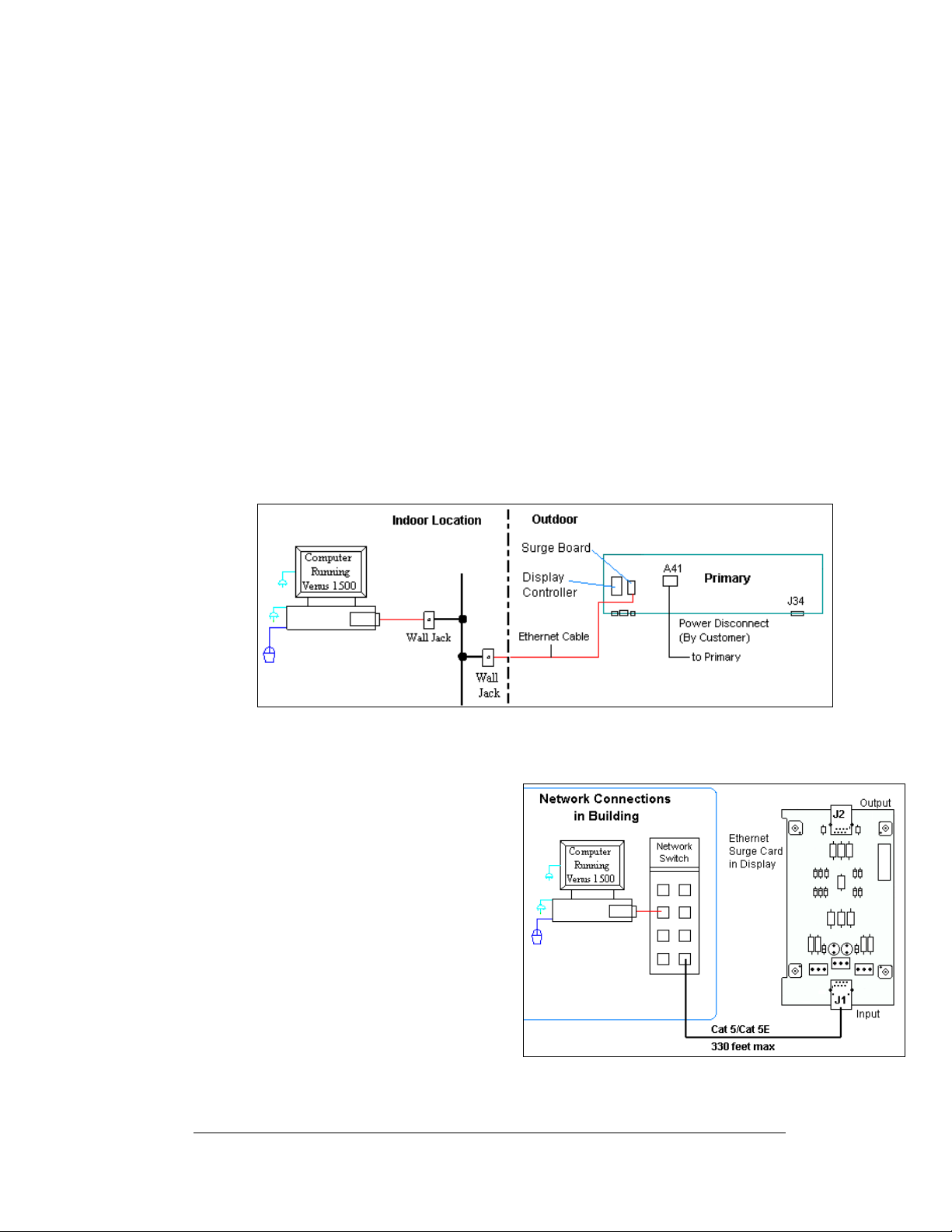
Ethernet (Wire)
The controller has a default IP address of 172.16.192.25. Use this address to connect
to the primary display, and then it can be changed to an address specified by the
network administrator. Electrical surges may enter over the cable; it is the
customer’s responsibility to protect their network.
An Ethernet controlled display, requires the use of an RJ45 cable from the network
to the display with the following connections:
1. Connect one end of the RJ4 5 cable to a network hub or switch.
2. From the network connection, cable is run to the Ethernet surge card in
the display.
3. The cable from the Ethernet hub to the surge board in the display must
be routed through conduit. Do not run signal and power through the
same conduit. Refer to
4. Note: Ethernet signal into the display does not allow for the normal
RS422 output signal to a second primary display. This includes both or
either the use of an interconnect cable or separate wiring between
displays.
Figure 31 for system layout.
Figure 31: Ethernet Display Layout
An Ethernet controlled display, uses a Cat-5 (W-1467) or Cat-5E (W-1384) cable
routed through separate conduit to the
display. The maximum distance is 330
feet (100 meters).
1. Connect from the Ethernet port
on the computer into the
Ethernet wall jack.
2. Run the cable through separate
conduit into the display and
connect to J1 on the Ethernet
surge board (0P-1229-2012) as
shown in
3. A five-foot RJ45 cable (W-
1506) connects for the J2 output
on the surge card to the
Ethernet port on the controller.
Electrical Installation
Figure 32.
Figure 32: Ethernet Signal Connection
3-17
Page 40
4. Note: It is the customer’s responsibility to protect their network from surges
back to their network.
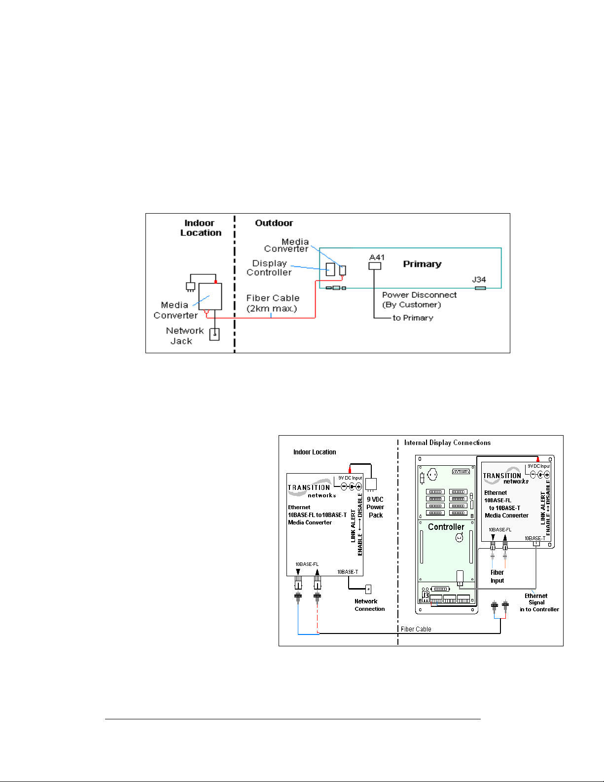
Ethernet (Fiber)
The controller has a default IP address of 172.16.192.25. Use this address to connect
to the primary display, and then it can be changed to an address specified by the
network administrator. Note: Ethernet signal into the display does not allow for the
normal RS422 output signal to a second primary display. This includes the both or
either the use of an interconnect cable or separate wiring between displays.
Figure 34: Fiber Ethernet Layout
A fiber Ethernet controlled display requires the use of two media converters
connected by a fiber cable. The first media converter is connected to the network and
the second one is connected to controller in the display as shown in
Figure 34.
A fiber Ethernet controlled
display requires the following
connections:
1. A media converter (A-
1778) connects to the
network hub or switch
using an RJ45 network
cable.
2. A DC wall pack
transformer provides
power to the media
converter from a 120
VAC outlet.
3. Connect the fiber cable
from the two jacks on
the first media
Figure 33: Fiber Ethernet Signal Connections
converter to the two
jacks on the second media converter in the display. (Always connect
transmit on one media converter to receive on the second, and receive to
transmit.)
3-18
Electrical Installation
Page 41
4. The media converter in the display connects to the controller via an RJ45
cable (W-1506). It also receives power from pins one and four of TB1 on
the controller.
5. The Ethernet connections are shown in
Figure 33.
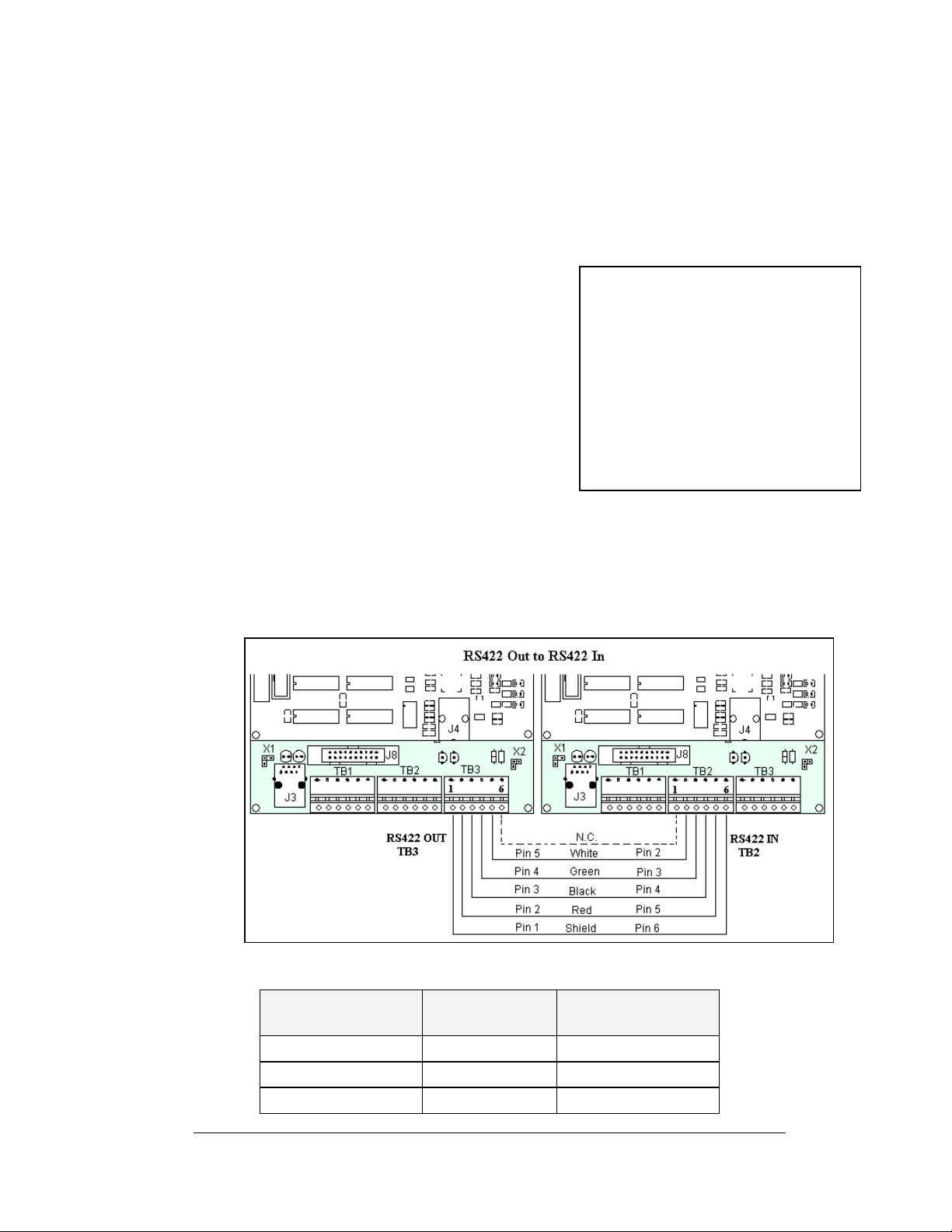
RS422 Interconnection
The quick connect cable is the most common method of terminating signal between
two displays. The interconnect cable goes from
the RS422 OUT on the first display to the RS422
IN on the second display. The 10-position, quick
connect cable comes in either 6 or 10 foot
lengths.
If the displays are not back-to-back, or are too far
apart for the quick connect interconnect cable to
reach, a 4-conductor shielded cable of the correct
length is used. One end will connect at the
“RS422 OUT” 6-position controller board
terminal block (TB3) in the first display, and
terminate on the “RS422 IN” 6-position controller
board terminal block (TB2) on the second display.
Note: If a temperature sensor is also used, a separate cable must also be used to
connect between controllers. Appendix C explains the connections for a
temperature sensor.
Figure 35: Display Interconnect Cable
Figure 36: RS422 Interconnection
Face A RS422 Out
(TB3)
Pin 1 (GND) Shield Pin 6 (GND)
Pin 2 (D2OUT-N) Red Pin 5 (D1IN-N)
Pin 3 (D2OUT-P) Black Pin 4 (D1IN-P)
Electrical Installation
RS422 Interconnection
Field Cabling
Face B RS422 IN
(TB2)
3-19
Page 42
Pin 4 (D2IN-N) Green Pin 3 (D1OUT-N)
Pin 5 (D2IN-P) White Pin 2 (D1OUT-P)
Pin 6 (Shield) Pin 1 (Shield)
Note:
When not using the quick connect interconnect cable; cabling must be in
conduit between displays.
Fiber Interconnection
A four-conductor fiber cable is used in connecting two or more displays in the Fiber
Interc
onnection method. Two fibers will be used for the connection and two will be
saved for spares. Connect the fiber cable to the fiber cards in the displays as
described in Drawing A-174344 and in the following table. The two jacks on the left
side of the fiber optic board (J2 and J3) will be used on the first display and the two
on the right side of the board (J4 and J5) will be used in on the second display.
Always connect transmit to receive and receive to transmit.
Fiber Interconnection
Face A Data Out Field Cabling Face B Data In
J2 Transmit (TX1) Color Varies J5 Receive (RX2)
J3 Receive (RX1) Color Varies J4 Transmit (TX2)
3.9 Optional Temperature Sensor
If you have an optional temperature sensor to be used with your display, see
Appendix C for mounting and signal connections.
3.10 First Time Operation
Each time the display is powered up; the display will run through an initialization in
which it will display the following:
1. Pr
oduct Name (Galaxy®)
2. Display Si
3. Sha
4. Bo
otloader Version (OS X.XX)
5. Firm
6. Firm
7. Har
8. Soft
9. IP A
10. Su
bnet Msk: ((default) Msk: 255. 2 55.0.0)
11. COM1 C
12. COM 2
13. Soc
14. Soc
15. Line F
ze (Row x Column)
ding (64 Mono)
ware Number (ED13305)
ware Revision (Rev X.XX)
dware Address (HW:XX)
ware Address (SW:XX)
ddress: ((default) 172.16.192.25)
onfiguration (C1:V15) ((Modem C1:V15) If a Modem is present)
Configuration (C2:RTD)
ket 3001: (IP 3001: V15)
ket 3002: (IP 3002: RTD)
requency (CLK: AUTO 60 Hz)
3-20
Electrical Installation
Page 43

16. Display Nam
After this sequence is complete, the display
the lower right hand corner of the display to show that the display has power, but no
messages are currently running.
e Description (Galaxy Row x Column)
will blank. A single pixel will flash in
Electrical Installation
3-21
Page 44

Page 45
Section 4: Maintenance and
Troubleshooting
Important Notes:
1. Disconnect power before performing any repairs or
maintenance work on the sign.
2. Only qualified service personnel may access internal sign
electronics.
3. The Daktronics engineering staff must approve ANY changes
made to the sign. Before altering the sign, you must submit to
the Daktronics engineering staff detailed drawings for the
proposed modifications for evaluation and approval or you
will void the warranty.
4.1 Maintenance and Troubleshooting Overview
Daktronics Galaxy® series AF-3197 signs are front accessible, meaning you can only
access the internal components from the front of the sign.
This section provides the following Galaxy
• Recommended Tools List provides a listing of all tools needed in order to
perform maintenance work on your display.
• Signal Routing Summaries give a basic explanation of the route that signal
travels through the sign.
• Power Routing Summaries show a basic explanation of the route that
power travels through the sign.
• Service and Diagnostics offer instructions for removing va ri o us si gn
components and explain the functions of circuit board connectors and the
meanings of diagnostic LEDs.
• Maintenance lists a number of steps to take to keep this Galaxy
safe, working order.
• Troubleshooting presents some possible sign malfunctions and provides a
number of possible causes for that malfunction.
• Replacement Parts List includes the part number and description of sign
components that could possibly need replacing during the life of this sign.
• Daktronics Exchange and Repair and Return Programs explain the
Daktronics component return policy.
®
sign information:
®
sign in
Maintenance and Troubleshooting
4-1
Page 46

4.2 Recommended Tools List
When performing maintenance work on your display, Daktronics recommends using
the following tools and placing them in a convenient, easy-access location.
7/32" Nut Driver to open the modules in front access displays.
3/16” Nut Driver to remove hardware from signal communication boards.
7/16" Wrench removes support hardware for power supplies.
#2 Phillips Screwdriver removes support hardware for power supp lies and
detaches power supplies.
4.3 Signal Summary
Reference Drawings:
Schematic, AF-3197-8-48x32x***-89, RGB................. Drawing A-184111
The signal routing for the display can be summarized as follows:
1. Data from the controller computer, which runs Venus
travels via RS232, RS422, modem, fiber optic cable, radio, or Ethernet into
the display.
2. For multiple face displays or a display network, an RS422 (most typical) or
fiber cable relays signal between the controller of the first display and the
controller in the second display. Note: The RS422 interconnection is not
allowed when the input to the first display is Ethernet.
3. From the controller, the signal then travels over 20-conductor ribbon cables
from the controller (J11 through J16 provides signal out) to J2 on the driver
of the first column of modules in the display.
4. Data exists at J1 and is relayed to J2 of the next driver board and so on,
traveling down the entire row of modules. The drivers use this display data
to control the LEDs. See Drawing A-184111 for further information.
®
1500 software,
4-2
Figure 37: AF-3197 Signal Flow Diagram
Maintenance and Troubleshooting
Page 47

4.4 Power Summary
Reference Drawings:
Schematic, AF-3197-8-48x32x***-89, RGB.................Drawing A-184111
Schematic; Power Supply Configurations, RGB..........Drawing A-184245
The following describes the internal display power routing:
1. Incoming power terminates at the panel board.
2. 120 VAC power is then relayed to the power supplies in the display, which
convert the power to DC voltage.
3. +14.7VDC power supplies power the modules in an RGB display. Refer to
Drawings A-184111 or A-184245 for power supply wiring information.
4. Power is also sent to the fans which cool the display and the transformer
that provides power to the controller and some additional communication
boards (modem, fiber, radio, or fiber Ethernet).
4.5 Display Access
Display access for all 89mm displays is normally from the front. To open the sign:
1. Locate the latch access fastener
on the module. It is centered on
the right side of the module.
2. With a 7/32" nutdriver, apply
pressure to latch and turn it a
quarter-turn counter-clockwise.
The module door will swing open
to the left.
3. Interior display components may
be accessed and the pixel strips
may be removed.
When closing a display, reverse the
previous steps and take note of the
following points:
• The weather-stripping on the back edge of the module is intact and in good
condition for preventing water from seeping into the sign.
• The module latches are fully engaged to create a water resistant seal around
the edge of the module. The module must be firmly seated against the sign
when the latches are fully engaged.
Figure 38: Opening Display
Maintenance and Troubleshooting
4-3
Page 48
4.6 Service and Diagnostics
Reference Drawings:
Component Layout, AF-3190-**X***-89mm ................ Drawing B-181666
The following sub-sections address servicing of the below display components:
• Line filter and ground bar
• Modules, drivers, and power supplies
The sub-sections also address any diagnostic LEDs, fuses, and signal/power
connectors found on the components.
Drawing B-181666 denotes the components as follows:
Component… Denoted As… Location…
Line Filters and Ground
Bar
Modules 0A-1259-3126 Over entire face of the display
Power Supplies 0A-1259-4410 Behind the modules; refer to
Line Filter
Reference Drawings:
Z Filter Assy, 2 W/Grnd Bar.................................. Drawing A-158472
Schematic, AF-3197-8-48x32x***-89, RGB.......... Drawing A-184111
You can replace the filter by first removing all connecting wires, and then releasing
the attachment hardware. Refer to Drawing A-158472 for more information. Install
the new filter and refer to Drawing A-184111 for the correct wiring.
0A-1259-4003 Left side, behind module AX02
Drawing B-181666.
4-4
Modules, Pixel Strips and Drivers
Reference Drawing:
Driver Assy; AF-3197-8x8-89mm-RGB....................... Drawing A-183737
Module Panel, AF-3197-8x8-89mm-RGB ................... Drawing A-182812
Driver; Large Pixel-8x8-RGB....................................... Drawing A-182600
A module consists of louvers, 16 pixel strips per module, and a driver board mounted
to the back. Refer to Section 4.5 to open a display via the modules and access the
pixel strips and driver boards.
A pixel strip is a circuit board with four LED pixel clusters mounted directly on it.
Each pixel strip is removable from the module. To remove a pixel strip from the
module:
1. Open the display as described in Section 4.5.
2. Disconn ect the power and signal connector from the strip you wish to
replace. Refer to Drawing B-182812 for more information.
Maintenance and Troubleshooting
Page 49
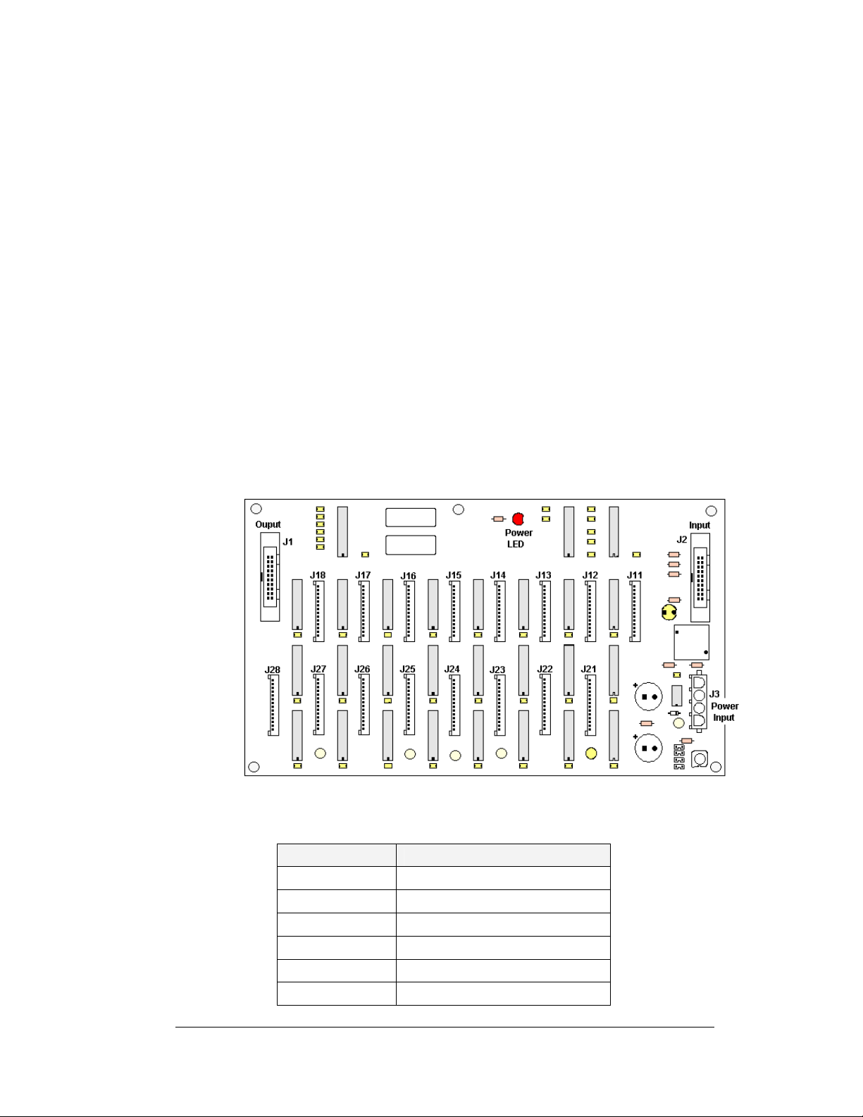
3. If the pixel strip you wish to replace is located behind the driver assembly,
label the signal cables and unplug them and the power connections on the
driver assembly and remove the four corner screws. Refer to Drawing A-
183737 for more information.
4. Remove the six wing nuts holding the pixel strip in place.
5. Gently lift the strip from the display.
6. Reverse the above procedure to install a new pixel strip.
The driver is a circuit board responsible for switching the intensity levels of the
LEDs. It is located inside the driver box and mounts on the back of the module. To
remove a driver board:
1. Open the display as described in Section 4.5.
2. Loosen the two #10 screws holding the driver cover in place.
3. Lift the cover off from the assembly. Refer to Drawing A-183737 for more
information.
4. Disconn ect all power and signal connections from the driver board.
5. Remove the four #6 nuts holding the board in place.
6. Gently lift th e board from the display.
7. Reverse th e above procedure to install a new driver board.
Figure 39: Driver Board
The following connectors are found on each driver board; refer to
LED/Connector Function
J1 Signal out to next driver board
J2 Signal in
J3 Power Input
J11-J18 Output to first row of pixel strips
J21-J28 Output to second row of pixel strips
DS1 Power indicator
Maintenance and Troubleshooting
Figure 39 above:
4-5
Page 50
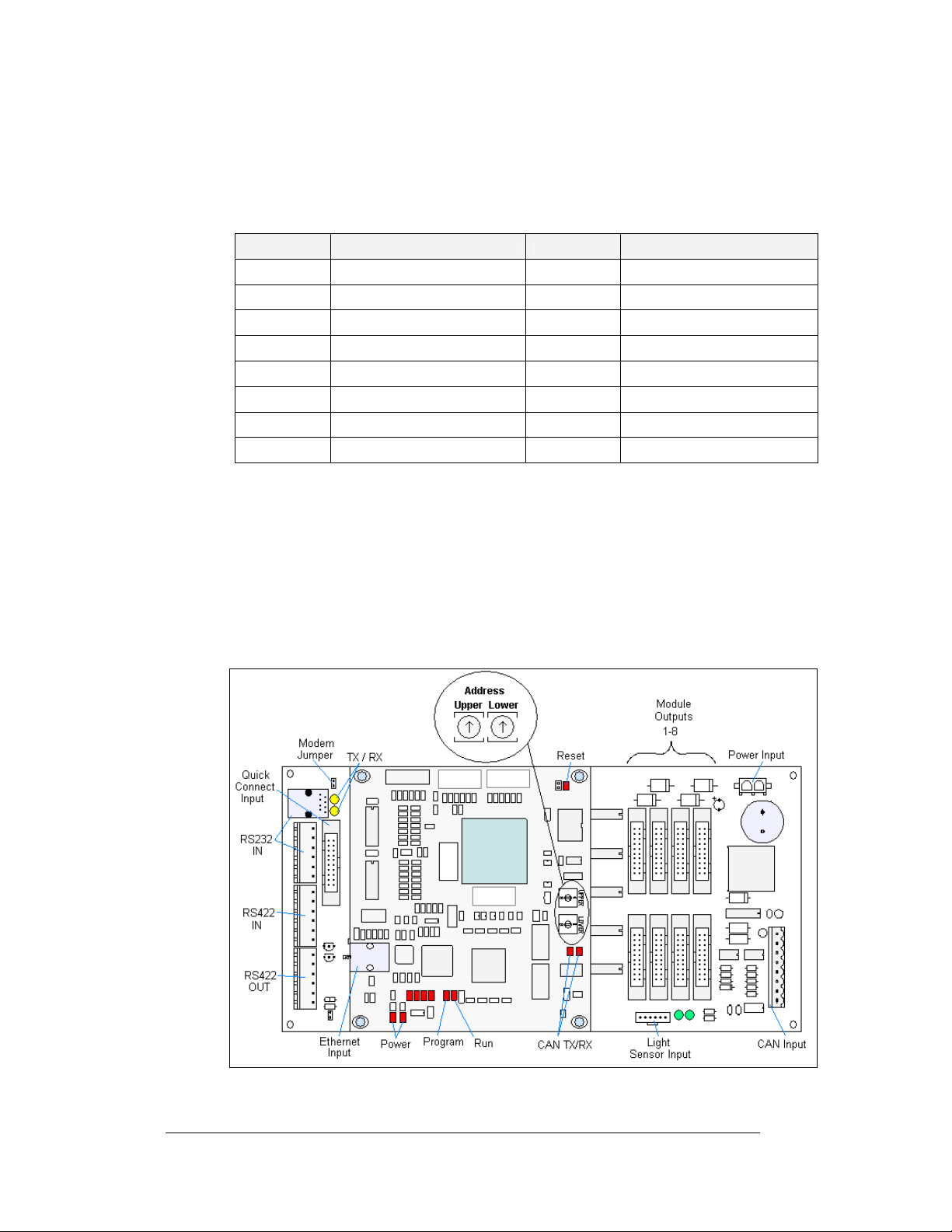
The connectors out to the pixel strips connect to the pixel strips in the following
manner:
Note: Columns are noted as how they are viewed from the front of the module (left
to right). When viewed from the back, the column order is from right to left.
Connector Pixel Strip Coordinates Connector Pixel Strip Coordinates
J11 Top Row, Column 1 J21 Bottom Row, Column 1
J12 Top Row, Column 2 J22 Bottom Row, Column 2
J13 Top Row, Column 3 J23 Bottom Row, Column 3
J14 Top Row, Column 4 J24 Bottom Row, Column 4
J15 Top Row, Column 5 J25 Bottom Row, Column 5
J16 Top Row, Column 6 J26 Bottom Row, Column 6
J17 Top Row, Column 7 J27 Bottom Row, Column 7
J18 Top Row, Column 8 J28 Bottom Row, Column 8
Controller
Reference Drawings:
Controller, Galaxy, 8-conn., J1087.............................. Drawing B-177838
Component Layout Diagram ....................................Refer to Appendix A
The controller sends data to the modules. Refer to the signal summary in Section 4.3
for more information and to the Component Layout Diagram for the posit i on of t he
controller board.
Figure 40 illustrates a typical controller.
4-6
Figure 40:Controller
Maintenance and Troubleshooting
Page 51
The rotary switches set the hardware address, which the software uses to identify that
particular display. When replacing a controller board, be sure to set the rotary
switches in the same address configuration as the defective controller. Each
controller in a network needs a unique address.
Note: Setting both rotary switches to address 0 (set the switches to 0 by rotating
them counter clockwise until the arrow points to 0), can activate a test mode. The
controller's power must be turned off and then turned back on to run the test mode.
The rotary switches follow a standard hexadecimal code. The table below shows
several common addresses.
Controller Address Settings
Address Upper Lower Address Upper Lower
Test Mode 0 0 10 0 A
1 0 1 11 0 B
2 0 2 12 0 C
3 0 3 13 0 D
4 0 4 14 0 E
5 0 5 15 0 F
6 0 6 16 1 0
7 0 7 17 1 1
8 0 8 … … …
9 0 9 240 F 0
Controller Address Settings
Maintenance and Troubleshooting
4-7
Page 52
Four diagnostic LEDs are located on the controller; the table below shows what each
LED denotes:
CPU
LED Color Function Operation
DS1 Red CAN TxD Flashes when controller is transmitting CAN
DS2 Red CAN RxD Flashes when controller is receiving CAN
DS3 Red System Reset Off when controller is functioning properly.
DS4 Red Run A steady flash indicates the controller is
DS5 Red U15
Programmed
DS7 Red Link On when Ethernet interface is in the link-up
DS8 Red Speed On when the Ethernet interface is at 100Mbps.
DS9 Red Duplex On when the Ethernet interface is at full duplex.
DS10 Red Collision Flashes when the Ethernet int erface detects a
DS12 Red +2.5V On when +2.5V power supply is functioning.
DS13 Red +3.3V On when +3.3V power supply is functioning.
information.
information.
Flashes at 1.5-second rate if the watchdog
timer is not being reset by controller.
running properly. Normal flash rate is about
once per second.
On when U15 contains a valid logic program.
condition. Flashes when the Ethernet chip
detects, transmits, or receives activity.
Off when the Ethernet interface is 10Mbps.
Off when the Ethernet interface detects a
collision in half-duplex.
collision in half-duplex.
Product Board
DS1 Green +5V On when +5V power supply is functioning.
DS2 Green +3.3V On when +3.3V power supply is functioning.
DS3 Yellow COM1 TxD Flashes when transmitting serial information.
DS4 Yellow COM1 RxD Flashes when receiving serial information.
Temperature/Light Sensor
DS1 Green +5V On when +5V power supply is functioning.
DS2 Red Run A steady flash indicates the controller is
running correctly. Normal flash rate is about
once a second. Flashes faster when the sensor
is transmitting temperature or light information.
4-8
Maintenance and Troubleshooting
Page 53
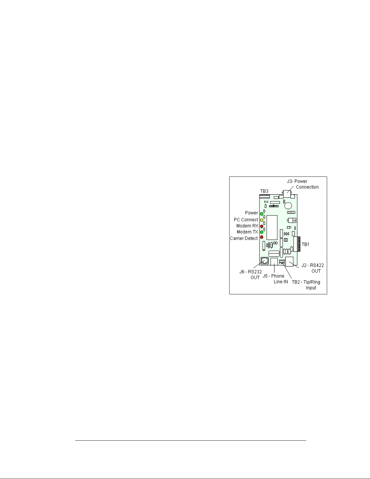
Complete the following steps to remove the controller from the display:
g
1. Disconnect pow er from J5.
2. Remove all power and signal connections from the board. “Locked”
connectors are released by pushing apart the latches, and then carefully
pulling them from the jack. When replacing the board, it is helpful to have
the cables labeled for easier replacement.
3. Remove each of the six screws holding the board in place.
4. Follow the previous steps in reverse order to install a new controller board.
Modem
Reference Drawings:
Enclosure Controller M2; Modem ................................Drawing A-177916
If a modem was included with the display, it is located inside the display next to the
controller board. Refer to Drawing A-177916 for modem location.
1. To replace a modem, first disconnect the
power and signal connections (refer to
Figure 41 for the location of the
connectors).
2. The modem is held in place with four
screws. Remove the screws with a 3/16”
nut driver and lift the modem out of the
display.
3. Install the new modem, replace the
screws, and reconnect power and signal
cables.
The modem module has 4 LEDs.
1. The power LED shou ld remain lit while
power is applied to the modem.
2. The modem RX and TX will flash when communicating.
3. The carrier detect LED will light when the modem has established
communication to another modem.
The modem board also has several input and output jacks:
1. J3 is the power input for 12VAC
2. TB2 is a pho enix connector to terminate the Tip and Ring wires
3. J5 is an RJ11 jack for termination of a pre-terminated phone line
4. J6 is the RS232 RJ45 output to the controller
5. J2, TB1, and TB3 are not used in this display application
A modem system requires the X1 jumper to be closed on the controller board. Refer
to
Figure 42 for the jumper location.
ure 41: Modem Board
Fi
Maintenance and Troubleshooting
4-9
Page 54
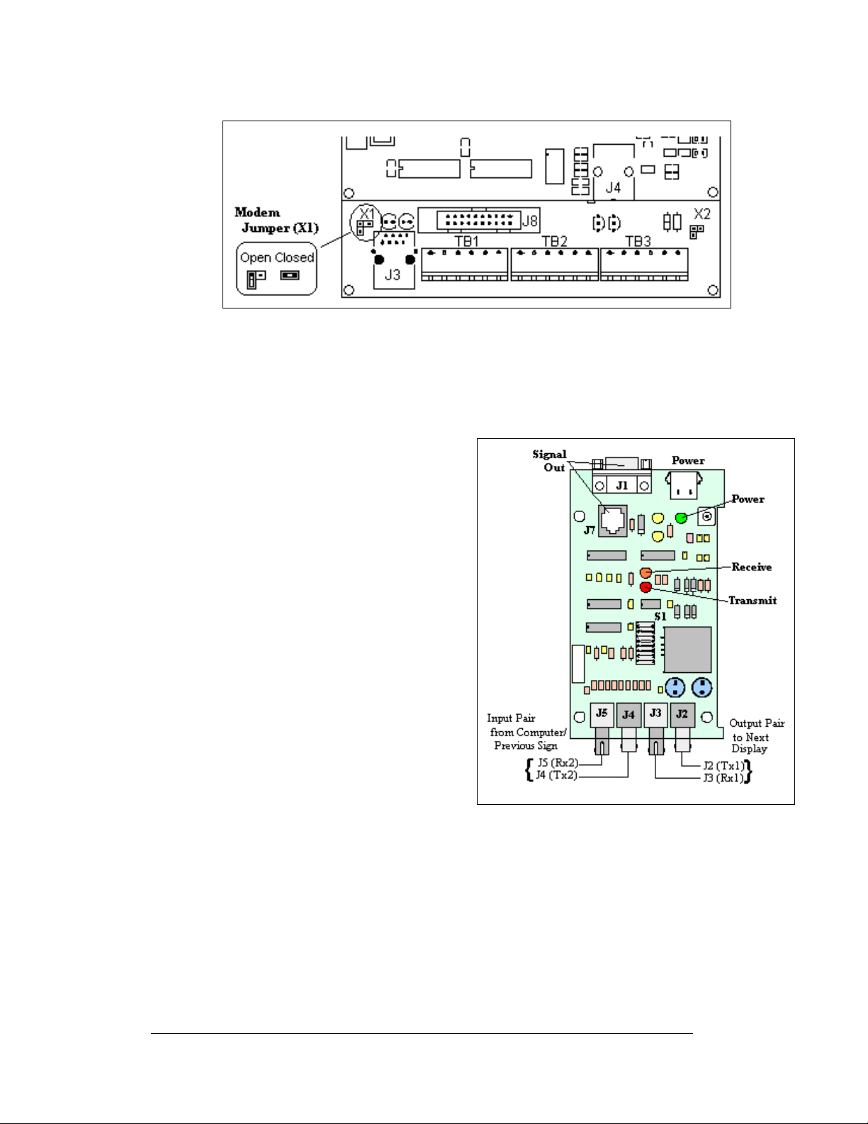
4-10
Figure 42: Modem Jumper Location
Fiber Optic Board
Reference Drawings:
Enclosure Controller M2; Fiber.................................... Drawing A-177918
To replace a fiber optic board:
1. Disconn ect the power and signal
connections (refer to Figure 43 for
disconnection of power).
2. The fiber optic board is held in
place with four screws. Carefully
remove them.
3. Install the new fiber optic board,
replace the screws and reconnect
power/signal cables.
The fiber module has three LEDs.
1. The power LED (DS1) should
remain lit while power is applied to
the module.
2. The receive LED (DS2) will flash
when the display fiber optic board is
accepting signal from the signal
converter.
3. The transmit LED (DS3) will flash
when the display fiber optic board is sending to the signal co nverter.
In addition, the fiber module has several input and output jacks:
1. J4 and J5 are the two fiber connectors, to which the fiber lines coming from
the fiber signal converter connect. (They can also be used for connecting to
fiber coming from a fiber optic board in another primary display.)
2. J6 is for the 12VAC power coming from the transformer.
3. J7 is used to transfer RS232 signal via a straight through RJ45 cable from
the fiber optic board to the display controller.
Figure 43: Fiber Optic Board
Maintenance and Troubleshooting
Page 55
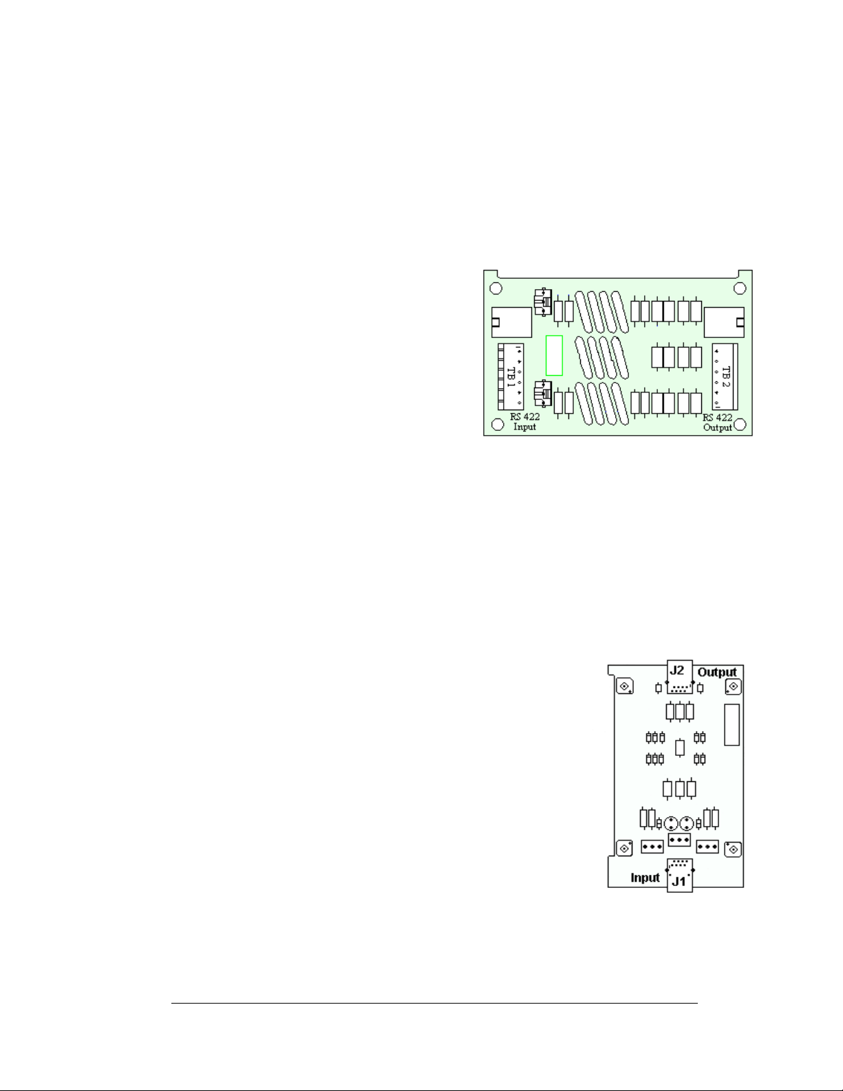
4. J2 and J3 could be used as output jacks to a fiber optic board in another
primary display.
5. J1 is not used in th is application.
RS422 Surge Suppressor
Reference Drawings:
Enclosure Controller M2; RS232/422..........................Drawing A-177905
1. Disconnect the signal connections
(refer to
2. The surge suppressor is held in
place with four screws. Carefully
remove them.
3. Install the new surge suppressor,
replace the screws, and reconnect
the signal cables.
The surge suppressor is an inline device
that is used to filter the RS422 data line. It
suppresses surges down to a low voltage in
order to protect the display controller's
RS422 input. The surge suppressor must be
firmly connected to the display’s chassis in
order to be effective. The mounting hardware used to secur e th e surge suppressor is
sufficient if it is fastened properly.
Figure 44).
Figure 44: Surge Suppressor
Ethernet Surge Card
Reference Drawings:
Enclosure Controller M2; Ethernet (0013) ...................Drawing A-229387
If an Ethernet surge board was included with the display, it is
located inside the display next to the controller board. Refer to
Drawing A-229387 for surge card location.
1. To replace the Ethernet surge board, first disconnect
the power and signal connections (refer to
2. The Ethernet surge card is held in place with four
screws. Carefully remove them using a 3/16” nut
driver.
3. Install the new Ethernet surge card, replace the screws
and reconnect power and signal cables.
The surge suppressor is an inline device that is used to filter the
RS422 data line. It suppresses surges down to a low voltage in
order to protect the display controller's RS422 input. The surge
suppressor must be firmly connected to the display’s chassis in
order to be effective. The mounting hardware used to secure
the surge suppressor is sufficient if it is fastened properly.
Figure 45).
Figure 45: Ethernet Surge Card
Maintenance and Troubleshooting
4-11
Page 56
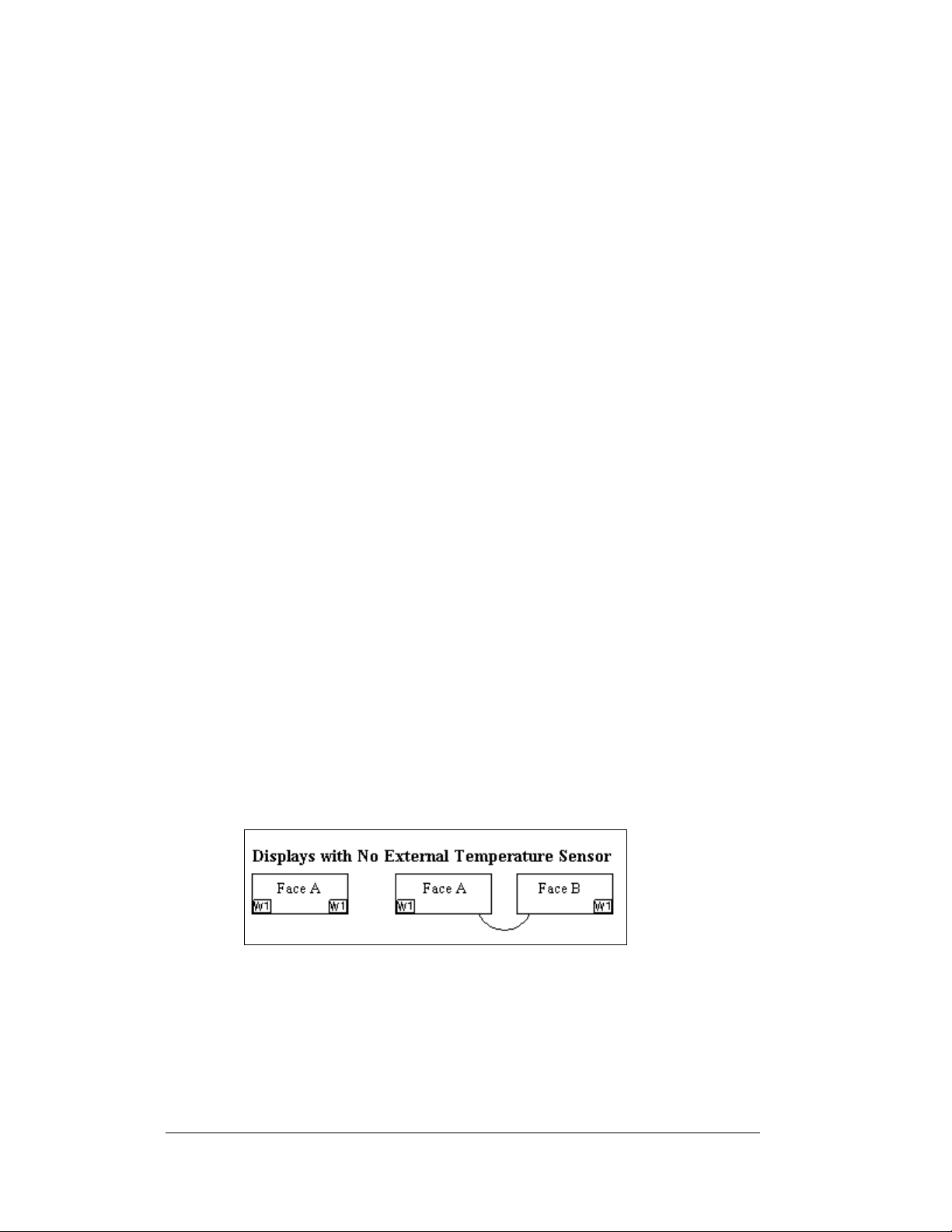
Media Converter
If a media converter was included with the display, it is located inside the display
next to the controller board.
1. To replace the media converter, first
disconnect the power and signal connections
(refer to
2. The media converter is attached to a plate
with four screws. Carefully remove them
using a 3/16” nut driver.
3. The media converter is held to the plate by
two screws. Release the two screws that hold
the media converter to the plate.
4. Install the new media converter, replace the
screws, reattach the plate, and reconnect the
power and signal cables.
The fiber media converter has the following input and
output jacks:
1. The fiber transmit and receive jacks are marked by arrows showing their
function. They are labeled “10BASE-FL”. The fiber cable from the indoor
media converter will connect to these jacks.
2. The input/output Ethernet signal to the display controller is routed through
an RJ45 jack, labeled “10BASE-T”.
3. The DC power input from the TB1 on th e display controller is connected
into the media converter at a jack labeled “9V DC Input”.
Figure 46).
Figure 46: Media Converter
Location of CAN termination jumper
Temperature and light sensors are controlled as part of a CAN network. For the CAN
network to work correctly, the network must be terminated at both ends of the
network. This is true for a single display, or multiple displays. The correct
terminations are completed during the building process. However, if the order or
number of displays is changed on-site, the terminating jumper may need to be
relocated.
Figure 47: Displays with No External Temperature Sensor
In the case of those displays that utilize a temperature sensor, the sensor is internally
terminated. Therefore, only one other termination needs to be made at the output of
the last sign in the network. The most common input location for the temperature
sensor is to the first display in the network.
4-12
Maintenance and Troubleshooting
Page 57
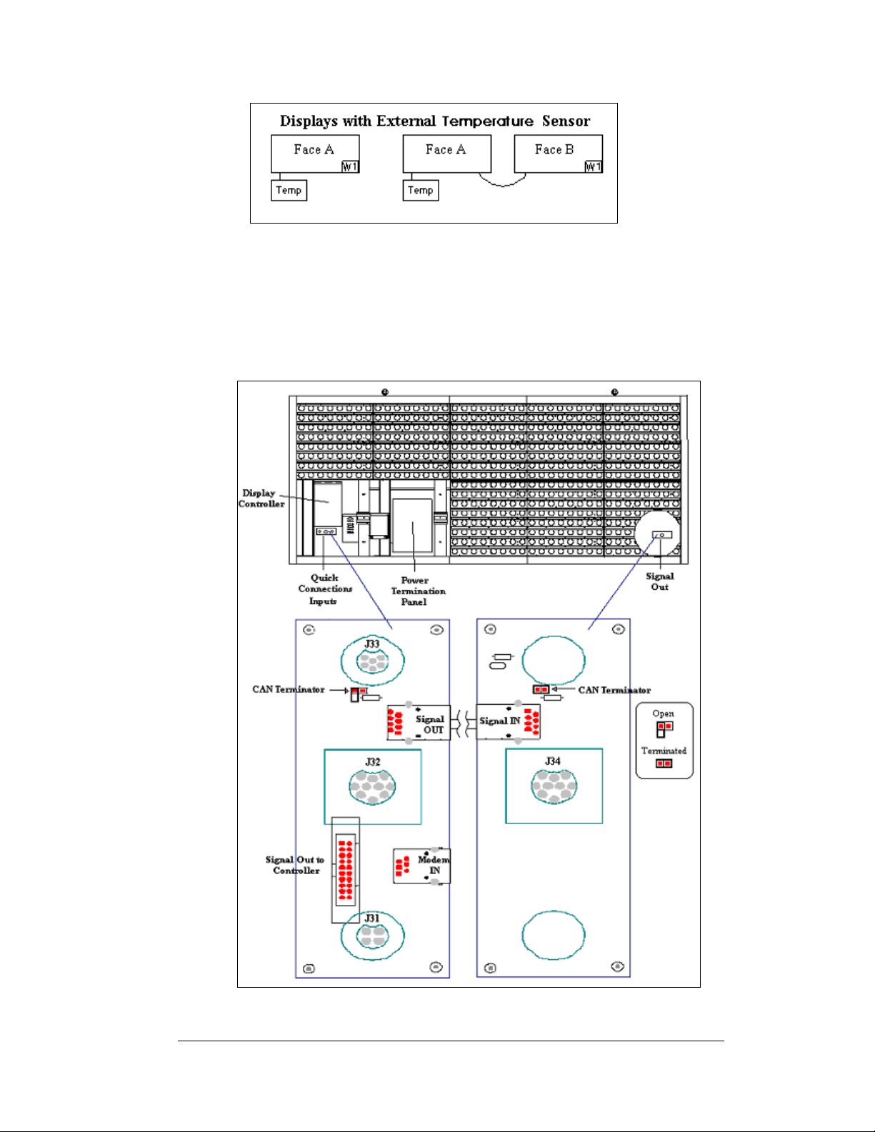
Figure 48: Termination Location for Displays with External Temperature
Sensor
The terminating jumper is located on the quick connect board on the inside of the
display. Most displays have both an input and an output quick connect board. When
no output board is available, the terminating jumper will be placed on the input board
of the last display. Therefore, both boards are shown in
Figure 47 and Figure 48.
Figure 49: Location of CAN Temperature Sensor Termination Jumper
Maintenance and Troubleshooting
4-13
Page 58

Power Supplies
The LED power supplies are identified as assemblies 0A-1259-4410 for AF-31 97
RGB displays. Each power supply controls two modules.
Complete the following steps to remove a power supply from the sign:
1. Op
2. Disconnect all the wi
3. Re
4. Fo
5. Verify
en the module directly in front of the failed power supply.
res connected to the power supply.
move the hardware holding the power supply in place to free the unit.
llow these steps in reverse order to install a new power supply.
power supply voltage.
4.7 Ventilation Systems
Check ventilation fans after 1,500 hours of operation and every 1,500 hours after that
to ensure the display cools properly. Check fans more often if the display is located
in a dusty or harsh weather environment (i.e. along a gravel road with dust laden air).
• 1,500 hours is equivalent to 83 days if the displa y operates for 18 hours a
day with the power to the display disconnected when not in use.
• 1,500 hours is equivalent to 62 days if the displ a y run s no n-stop for 24
hours a day.
Attention: Shu
when the display is not operating exposes electrical components to excess
condensation, which shortens their life.
Each time you open the display, for whateve
fans:
• Check the fan blades for dirt and debris. If the fan blades have a large
• Spin the fan blades with a pen or pencil to ensure that the bearings are free
To check the operation of the fans:
• Hold your hand or a piece of light paper beneath the fan to detect air
• Press button on the internal thermostat and ensure they run freely.
• If the fan does not turn or does not operate smoothly, replace it.
t off power to the display when it is not in use. Leaving the power on
accumulation of dirt and debris, change the filters more often. Keep the fan
blades clean to maintain fan efficiency and ensure proper cooling.
and the fan is still in balance.
movement. If the operation of a fan is questionable, a fan-test should be
performed
r reason, take a minute to inspect the
4-14
Maintenance and Troubleshooting
Page 59

4.8 Thermostats
Reference Drawings:
Component Layout, AF-3190-**X***-89mm.................Dra
A thermostat is used when the ventilation fans operate in the display. Refer to the
D
rawing 181666 for the location of the thermostat. The ventilation fans turn on
when the inside of the display reaches 85° F (29 C), and turn off at 70° F (21 C).
4.9 Sign Maintenance
Perform a yearly inspection to maintain safe and dependable display operation. This
inspection should address the following issues:
• Loose Hardware
Verify fasteners, such as bolts and riv
tighten, and replace fasteners as required.
• Excessive Dust Buildup
Occasionally it may be necessary to vacuum the inside of the display
cab
inet to remove dust/dirt buildup that may interfere with airflow.
• Water Intrusion – Water Stain Marks
Water can enter the sign where weather stripping has come loose or
det
eriorated, where fasteners have come loose allowing gaps in the panels,
or where moisture may be entering around hardware. Check electronic
components for signs of corrosion.
• Corrosion
Check the paint; look for possible corrosion, especially at footings,
str
uctural tie points, and ground rods.
If you notice any of the above conditions, take ac
wing B-181666
ets, have not come loose. Check,
tion to correct the situation.
4.10 Weather Stripping
To ensure the display is weather resistant, Daktronics provides weathe r str i pping
around the entire display and around each module. The weather stripping must be
properly installed at all times or water may leak into the display, damaging the
components.
Maintenance and Troubleshooting
4-15
Page 60
4.11 Troubleshooting
This sub-section contains some symptoms that you may encounter with the displays.
This list does not include every possible symptom, but does represent common
situations that may occur.
Symptom/Condition Possible Cause/Remedy
One or more LEDs on a single
module fail to light.
One or more LEDs on a single
module fail to turn off.
A section of the sign is not
working. The section extends all
the way to the right side of the
sign.
One row of modules does not
work or is garbled.
A group of modules, which share
the same power supply
assembly, fail to work.
Entire sign fails to work. • Check for proper line voltage into the
Temperature always reads -196
degrees
• Replace/check cables on the module.
• Replace pixel strip.
• Replace the driver.
• Replace/check cables on module.
• Replace pixel strip.
• Replace the driver.
• Replace/check the cables.
• Check power to the modules.
• Replace the first driver on the left
side of the first module that is not
working.
• Replace the second driver that is not
working.
• Replace the power supply assembly
on the first module that is not
working.
• Replace/check the cables.
• Replace first driver.
• Replace controller.
• Check the fuses in the power
termination box.
• Check power supply voltage.
• Replace the power supply assembly.
power termination panel.
• Check the fuse in the power
termination panel.
• Check/replace the ribbon cable from
the controller to the driver.
• Check the voltage settings on the
power supplies.
• Verify proper use of the software in
the operation manual.
• Replace the controller.
• Check/replace the signal cable to the
controller.
• Check temperature sensor
connections.
• Replace the temperature sensor.
• Replace the controller.
4-16
Maintenance and Troubleshooting
Page 61

Sign is stuck on bright or dim.
• Check Manual/Auto dimming in
Venus 1500 software.
• Check light detector cable.
• Check light detector for obstructions.
• Replace the light detector.
• Replace the controller.
4.12 Initial Operation Information
Every time the display is operated, the display will run through an initialization in
which it will display the following:
1. Pr
oduct Name (Galaxy®)
2. Display Si
3. Sha
4. Bo
otloader Version (OS X.XX)
5. Firm
6. Firm
7. Har
8. Soft
9. IP A
10. Su
bnet Msk: ((default) Msk: 255. 2 55.0.0)
11. COM1 C
12. COM 2
13. Soc
14. Soc
15. Li
ne Frequency (CLK: AUTO 60 Hz)
16. Display
After this sequence is complete, the display
the lower right hand corner of the display to show that the display has power, but no
messages are currently running.
ze (Row x Column)
ding (64 Mono)
ware Number (ED13305)
ware Revision (Rev X.XX)
dware Address (HW:XX)
ware Address (SW:XX)
ddress: ((default) 172.16.192.25)
onfiguration (C1:V15) ((Modem C1:V15) If a Modem is present)
Configuration (C2:RTD)
ket 3001: (IP 3001: V15)
ket 3002: (IP 3002: RTD)
Name Description (Galaxy Row x Column)
will blank. A single pixel will flash in
Maintenance and Troubleshooting
4-17
Page 62
Replacement Parts List
The following table contains some of the items in this display that may need
replacing over time. Many of the parts within the display also list their part numbers
on labels affixed to them.
To prevent theft, Daktronics recommends purchasi
manuals and replacement/spare parts.
Part Description Part Number
Controller 0A-1229-0009
Signal Converter-wire 0A-1127-0255
Signal Converter-Fiber 0A-1127-0256
Serial Cable; RS232 DB9F to DB25M, 6' W-1249
Modem in display 0P-1279-0003
Light Detector 0P-1247-0003
Digital Temp Sensor 0P-1247-0008
Fiber Board in Display 0P-1127-0024
Surge Suppression Board, RS422 0P-1146-0031
Ethernet Surge Board 0P-1229-2012
Media Converter A-1778
Radio Client 0A-1146-0078
Radio Server (Outdoor) 0A-1146-0079
Cable; 18” RJ45; 8-cond.; Straight 0A-1229-0054
Quick Connect Interface, Input 0P-1229-2001
Quick Connect Interface, Output 0P-1229-2002
Thermostat Enclosure 0A-1213-4024
Cable; Ribbon assy, 20 position, 18” W-1387
Cable; Ribbon Assy, 20 Position, 60" 0A-1000-0021
Cable; Ribbon Assy, 20 Position, 84" 0A-1000-0023
Cable Assy, 14P to 14 P, 30” W-1809
Cable; 10-pin male to 10-pin male, 4', QC W-1483
Cable; 10-pin male to 10-pin male, 10', QC W-1500
RGB Pixel Board, 4x1 0P-1261-0012
Driver Board, 8x8, RGB, J-1087 0P-1261-0011
Power Supply Assembly (1, A-1593) 0A-12 59-4410
Fan; 134CFM, 120VAC, 22W, 60Hz, 4.5” B-1053
Line Filter Assembly 0A-1259-4003
Manual; Venus 1500 Operator’s
Manual; Venus 1500 Radio
ng a lockable cabinet to store
ED-13530
ED-13932
4-18
Maintenance and Troubleshooting
Page 63

4.13 Daktronics Exchange and Repair and Return
Programs
To serve customers' repair and maintenance needs, Daktronics offers both an
Exchange Program and a Repair and Return Program.
Daktronics' unique Exchange Program is a quick, economical service for replacing
key
components in need of repair. If a component fails, Daktronics sends the
customer a replacement, and the customer, in turn, sends the failed component to
Daktronics. This not only saves money, but also decreases display downtime.
Daktronics provides these plans to ensure users get the most from their Daktronics
p
roducts, and it offers the service to qualified customers who follow the program
guidelines explained below. Please call the Help Desk – 877-605-1113 – if you have
questions regarding the Exchange Program or any other Daktronics service.
When you call the Help Desk, a trained service technician will work with you to
so
lve the equipment problem. You will work together to diagnose the problem and
determine which replacement part to ship. If, after you make the exchange, the
equipment still causes problems, please contact our Help Desk immediately.
If the replacement part fixes the problem, package
and packaging in which the replacement part arrived, fill out and attach the enclosed
UPS shipping document, and return the part to Dak tronics. In most circumstances,
you will be invoiced for the replacement part at the time it is shipped. This bill,
which represents the exchange price, is due when you receive it.
Daktronics expects immediate return of an exchange part if it does not solve the
problem
damaged due to acts of nature or causes other than normal wear and tear.
If you do not ship the defective equipment Daktronics within 30 working days from
the invoice
outright (with no exchange), and you will be invoiced for it. This second invoice
represents the difference between the exchange price and the full purchase price of
the equipment. The balance is due when you receive the second invoice. If you
return the exchange equipment after 30 working days from the invoice date, you will
be credited for the amount on the second invoice, minus a restocking fee. To avoid a
restocking charge, you must return the defective equipment within 30 days
from the invoice date.
Daktronics also offers a Repair and Return Program for items not subject to
excha
Return Materials Authorization: To
representative prior to shipment to acquire a Return Material Authorization (RMA)
number. If you do not have a local representative, call the Daktronics Help Desk for
the RMA. This expedites repair of your component when it arrives at Daktronics.
. The company also reserves the right to refuse equipment that has been
date, Daktronics assumes you are purchasing the replacement part
nge.
return parts for service, contact your local
the defective part in the same box
Maintenance and Troubleshooting
4-19
Page 64

Packaging for Return: Packag
e and pad the item well so that it will not be damaged
in shipment. Electronic components such as printed circuit boards should be installed
in an enclosure or placed in an antistatic bag before boxing. Please enclose your
name, address, phone number, and a clear description of symptoms.
This is how to reach us:
Mail:
Customer Service, Daktronics Inc.
PO Box 5128
331 32nd Ave
Brookings SD 57006
Phone:
Daktronics Help Desk: 877-605-1113 (toll free)
or 605-697-4034
Fax: 6
05-697-4444
E-mail: h
elpdesk@daktronics.com
4-20
Maintenance and Troubleshooting
Page 65

Appendix A: Reference Drawings
Refer to Section 1.1 for information on reading drawing numbers. This appendix lists the
following drawings in numerical order by size (A, B, etc.).
Z Filter Assy, 2 W/Gnd Bar
Assembly, Grounding and Fan
Fan Assembly Detail
System Riser Diagram, RS
System Riser Diagram, RS
System Riser Diagram, Modem.......................................................Dra
System Riser Diagram, Fiber
Assy, Grounding and Fan Harness
Enclosure Controller M2; RS232/422
Enclosure Controller M2; Modem
Enclosure Controller M2; Fiber
Enclosure Controller M2; RS422 Echo
Driver Assy; AF-3197-8x8-89mm-RGB
Power Specs, AF-3197, RGB LEDs
Schematic, AF-3197-8-48x
Schematic; Power Supply Configurations
Layout, Pnl Bd, 8-48x32-112, 89mm, 1 Phas
Layout, Pnl Bd, 8-48x32-112, 89mm 3 Phas
System Riser Diagram, Radio
Schem, Sig Wiring, Internal, W/Quick Connect PCB
Cntrlr; Galaxy, 8 Conn, J1087
Component Layout, AF-3190-**x**-89mm
Driver; Large Pixel-8x8-RGB, J
Module Panel, AF-3197-8x
Shop Drawing, AF-3197-8x**-89mm
Shop Drawing, AF-3197-16x***-89mm-RGB
Shop Drawing, AF-3197-24x***-89mm-RGB
Shop Drawing, AF-3197-32x***-89mm-RGB
Shop Drawing, AF-3197-40x***-89mm-RGB
Shop Drawing, AF-3197-48x***-89mm-RGB
Block Diagram, Power, AF-3197, 89mm
..............................................................Drawing A-158472
Harness .........................................Drawing A-161307
........................................................................Drawing A-164433
422........................................................Drawing A-174135
232........................................................Drawing A-174341
wing A-174342
..........................................................Drawing A-174344
.................................................Drawing A-175194
..............................................Drawing A-177905
....................................................Drawing A-177916
........................................................Drawing A-177918
............................................Drawing A-177921
...........................................Drawing A-183737
................................................Drawing A-183906
32x***-89, RGB.....................................Drawing A-184111
.......................................Drawing A-184245
e................................Drawing A-184316
e.................................Drawing A-184321
.........................................................Drawing A-185359
......................Drawing B-177662
.........................................................Drawing B-177838
......................................Drawing B-181666
-1087..............................................Drawing B-182600
8-89mm-RGB .......................................Drawing B-182812
-RGB......................................Drawing B-183982
...................................Drawing B-183983
...................................Drawing B-183984
...................................Drawing B-183985
...................................Drawing B-183986
...................................Drawing B-183987
.........................................Drawing B-184326
Appendix A: Reference Drawings
A-1
Page 66
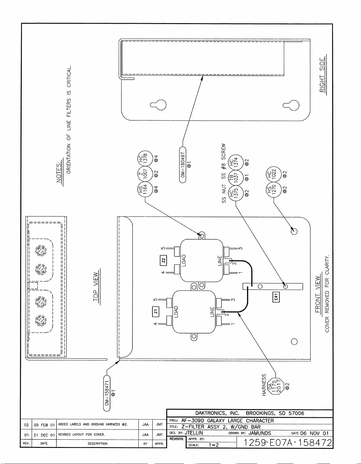
Page 67
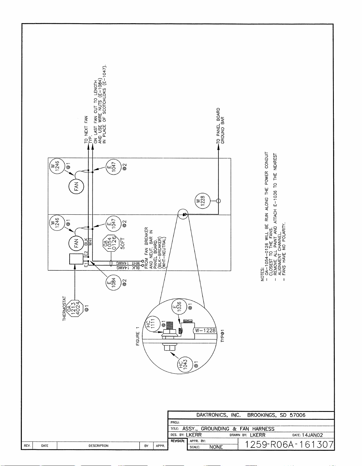
Page 68
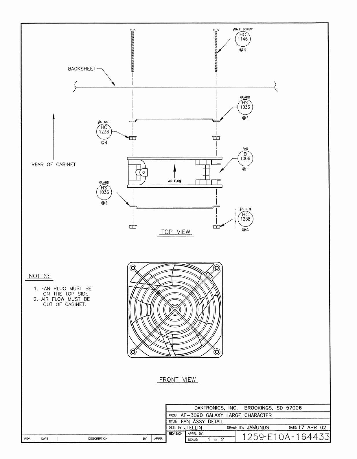
Page 69
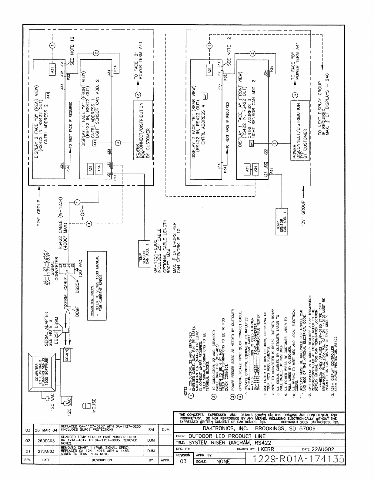
Page 70
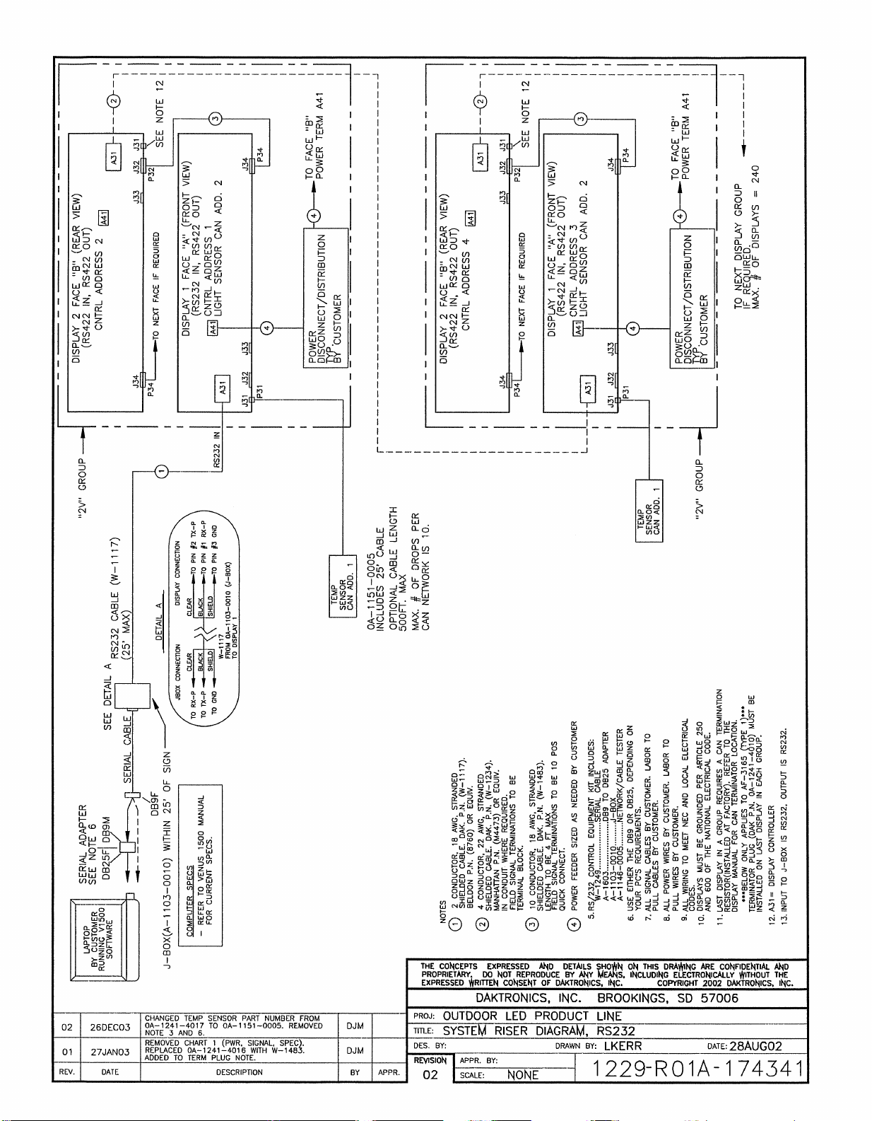
Page 71
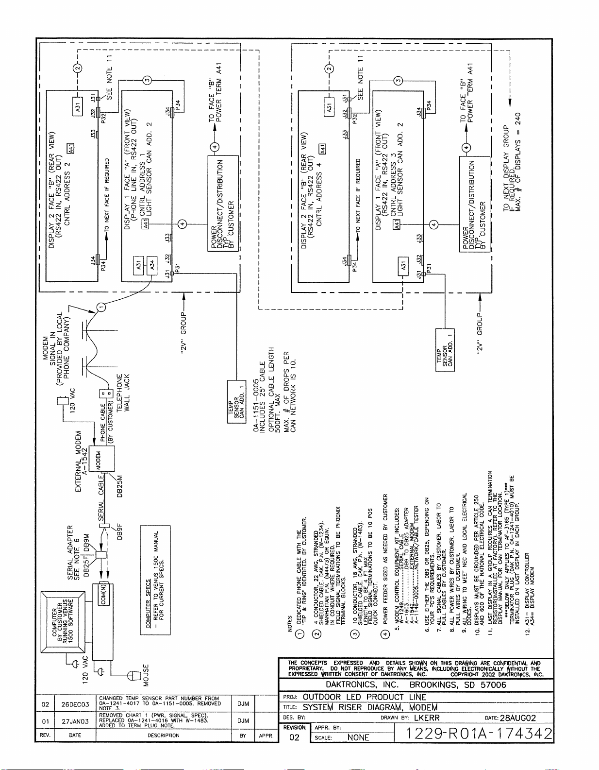
Page 72
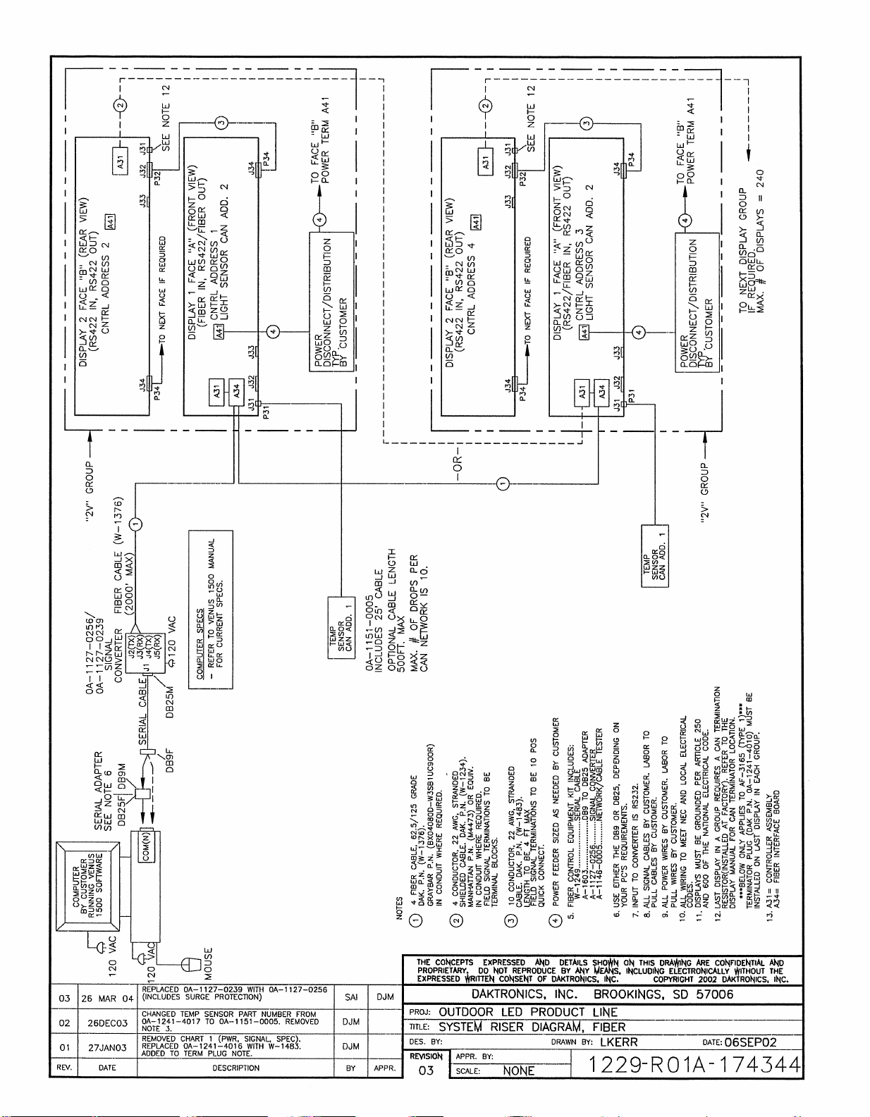
Page 73
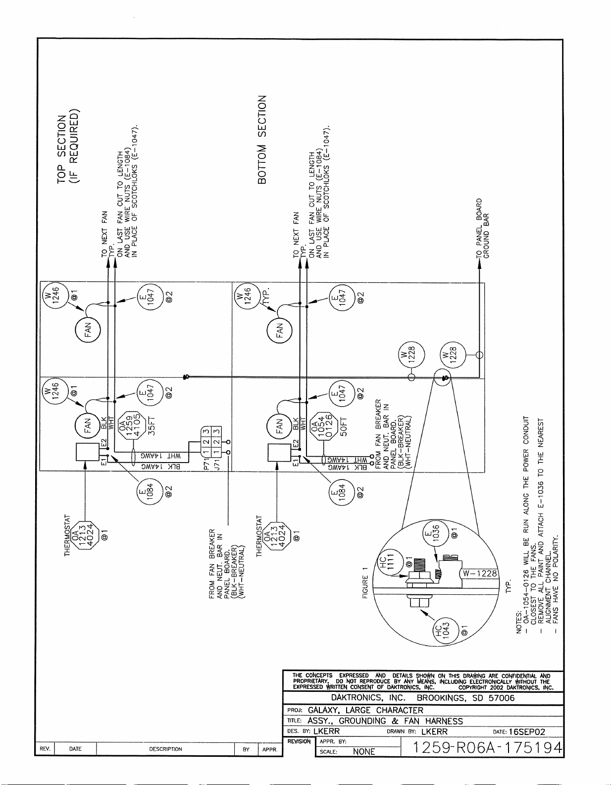
Page 74
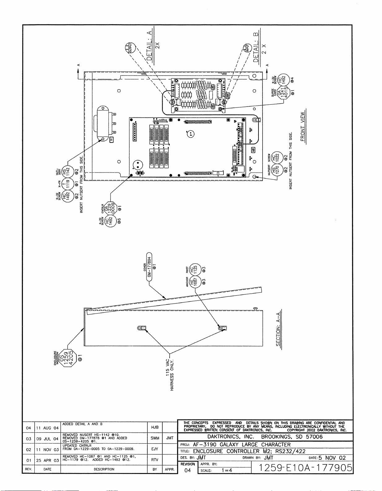
Page 75
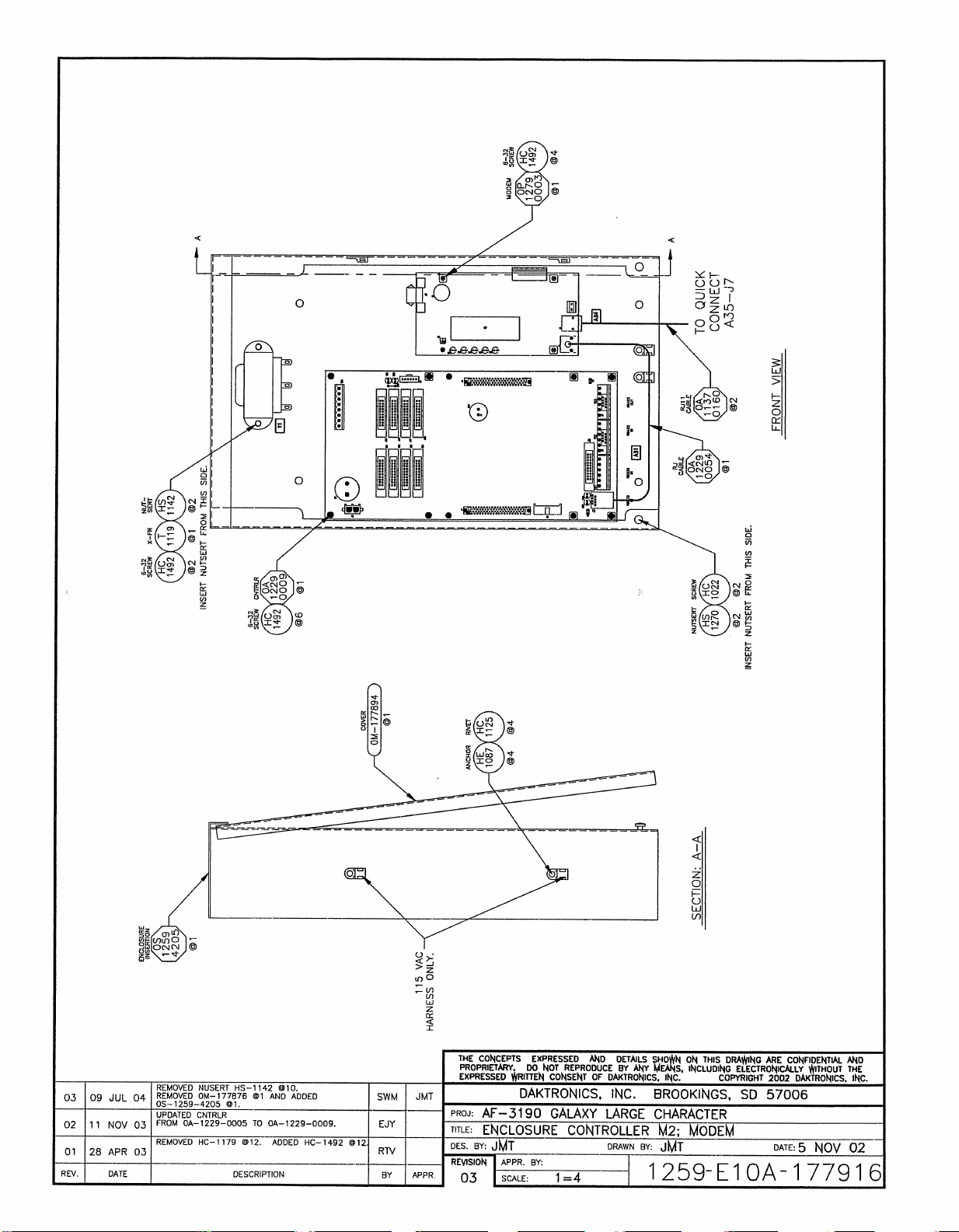
Page 76
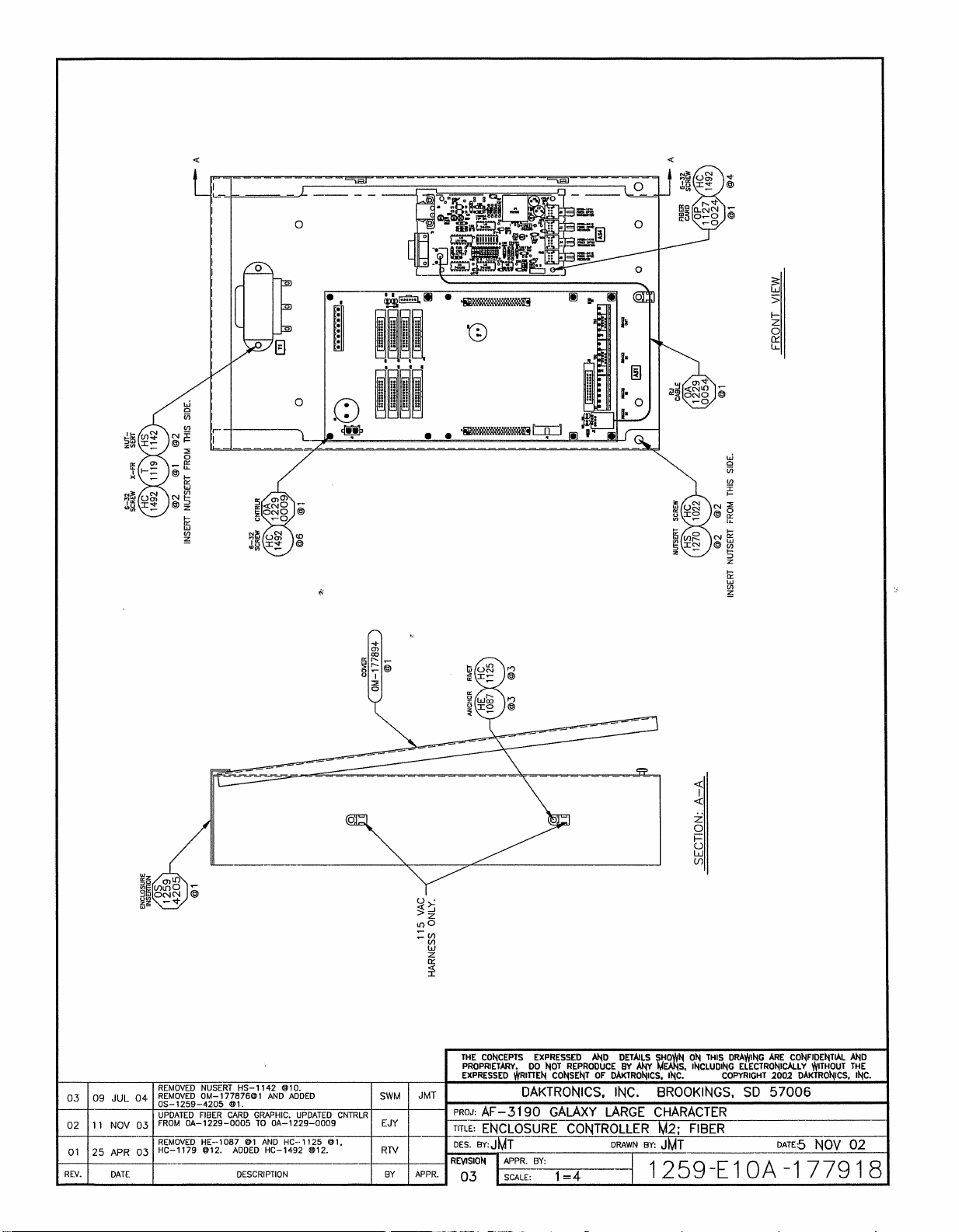
Page 77
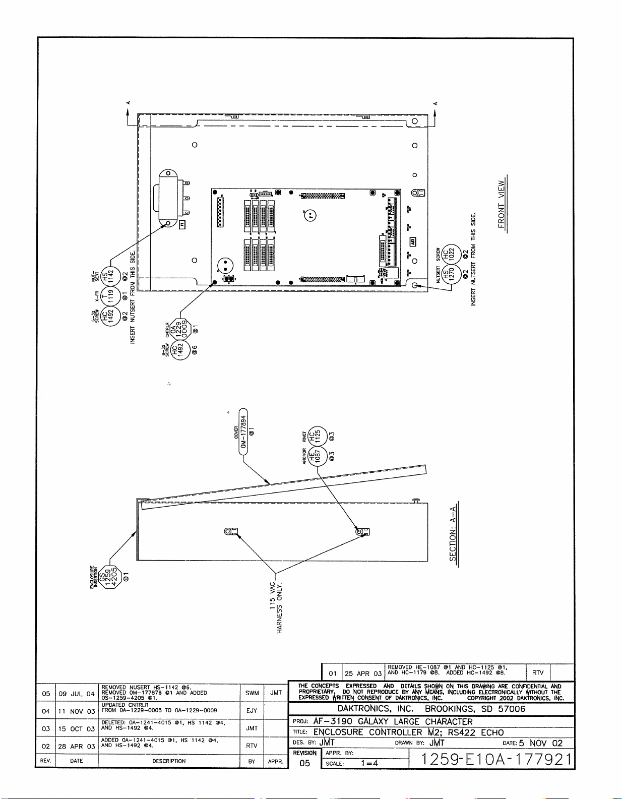
Page 78
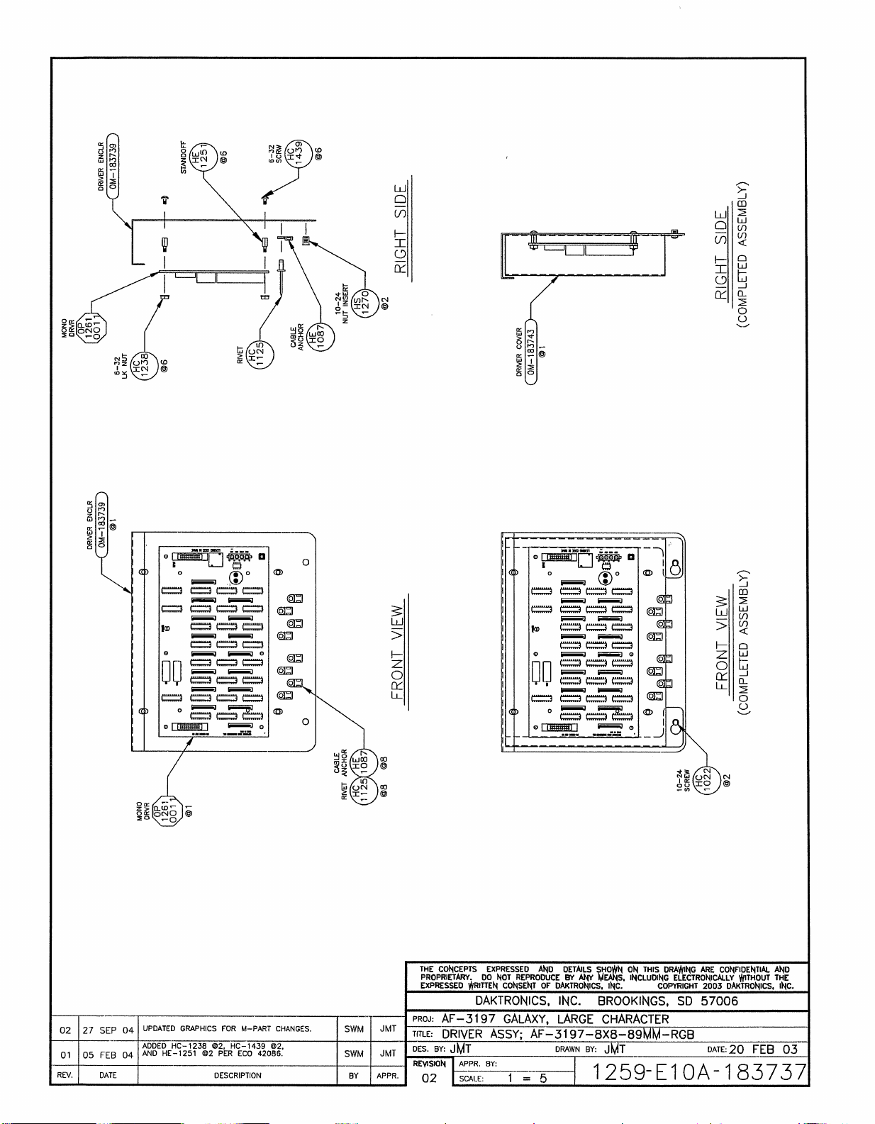
Page 79
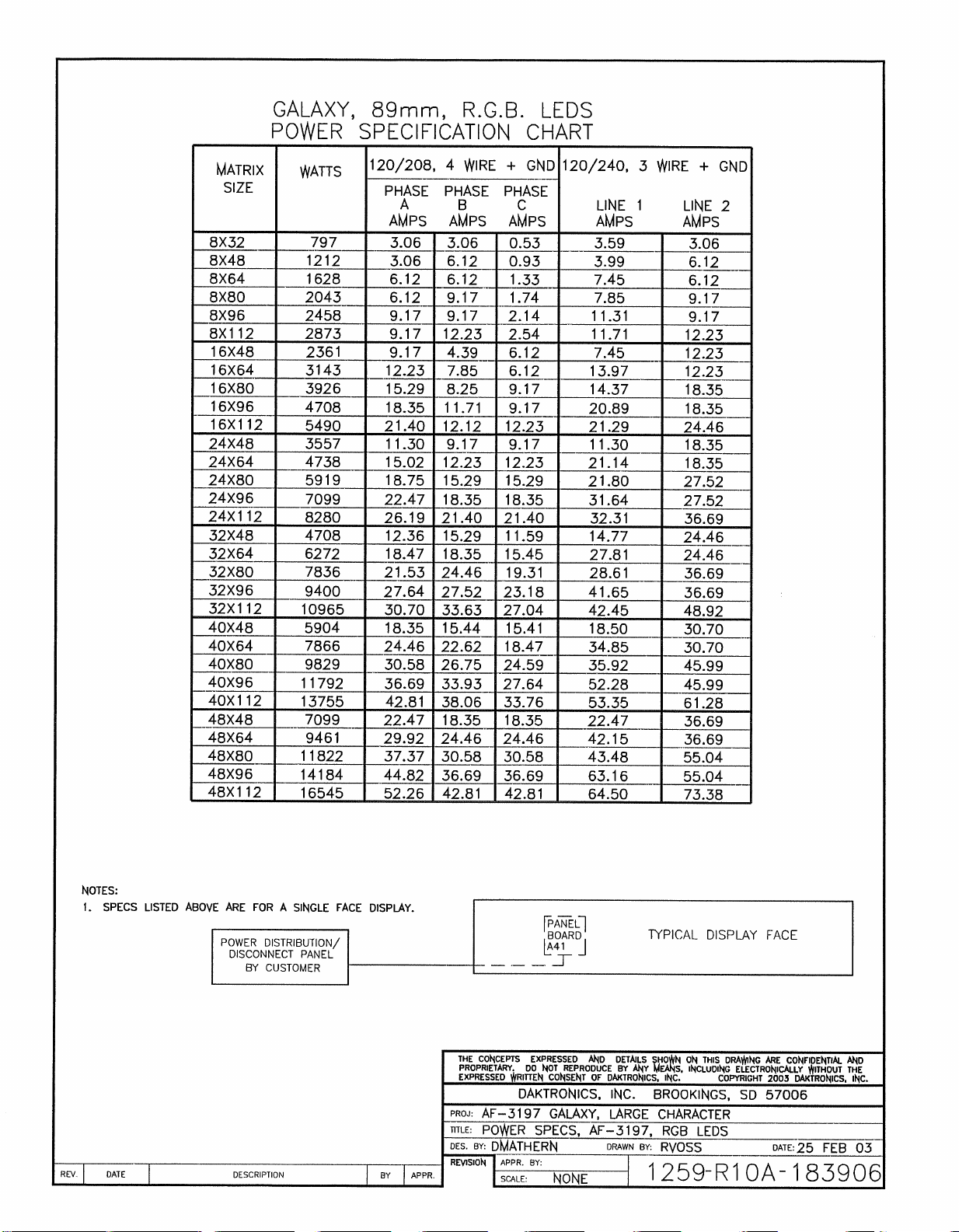
Page 80
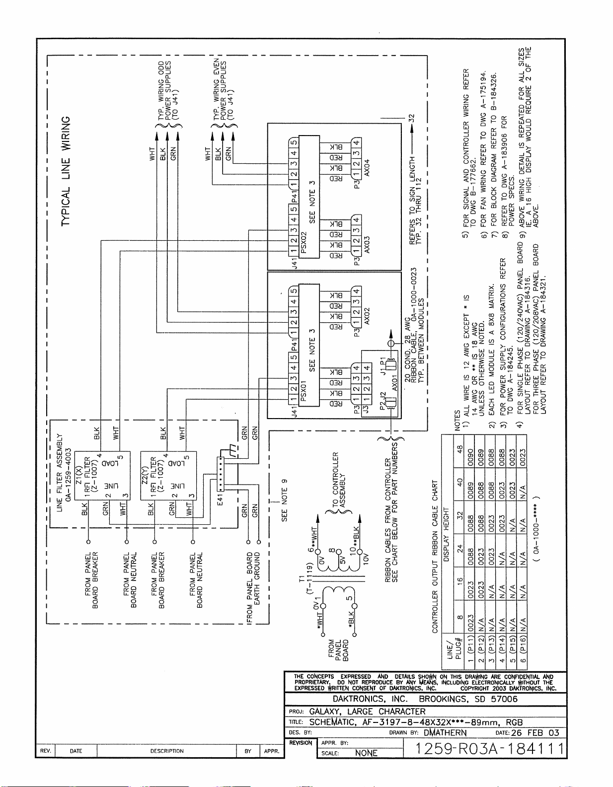
Page 81
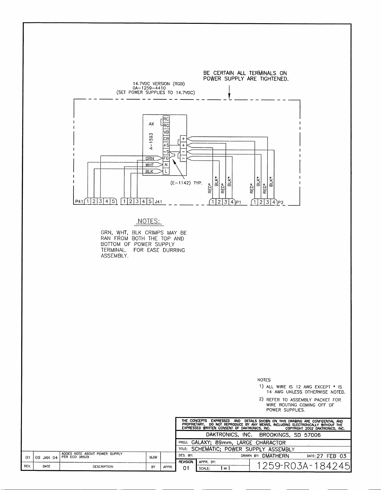
Page 82
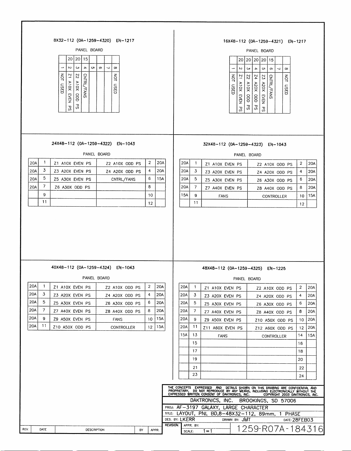
Page 83
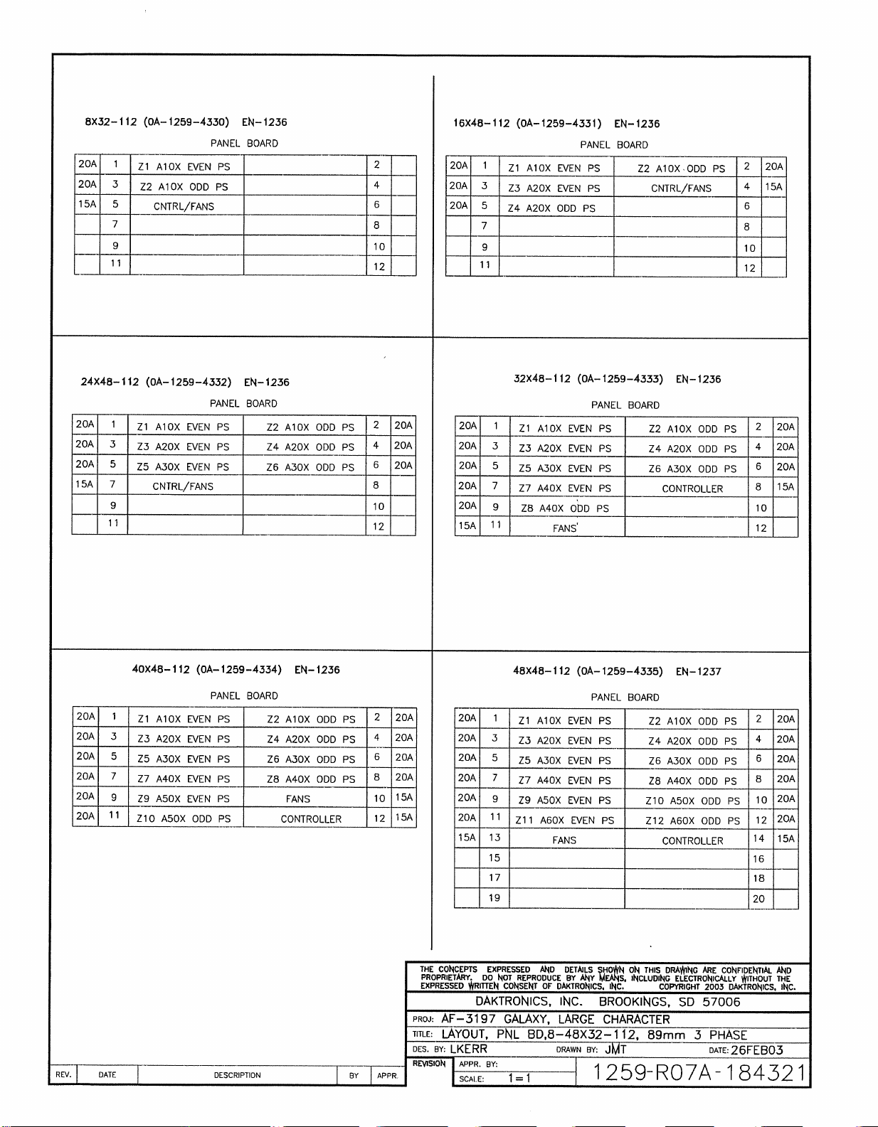
Page 84
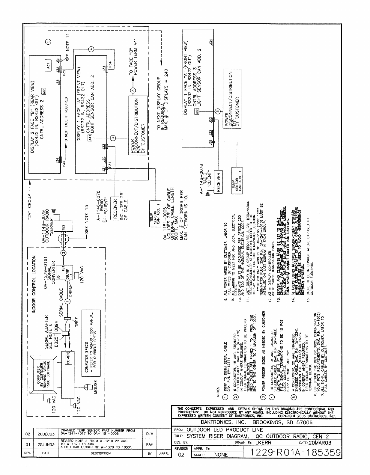
Page 85

Page 86
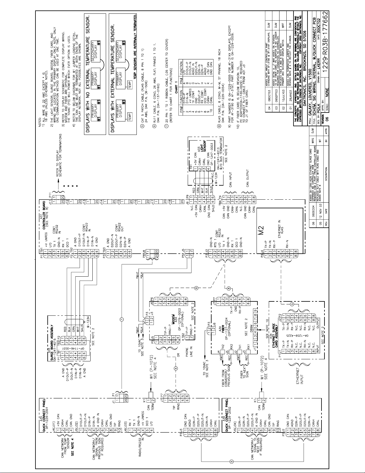
Page 87
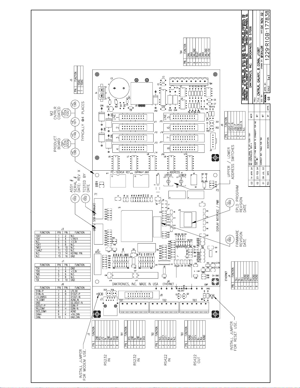
Page 88
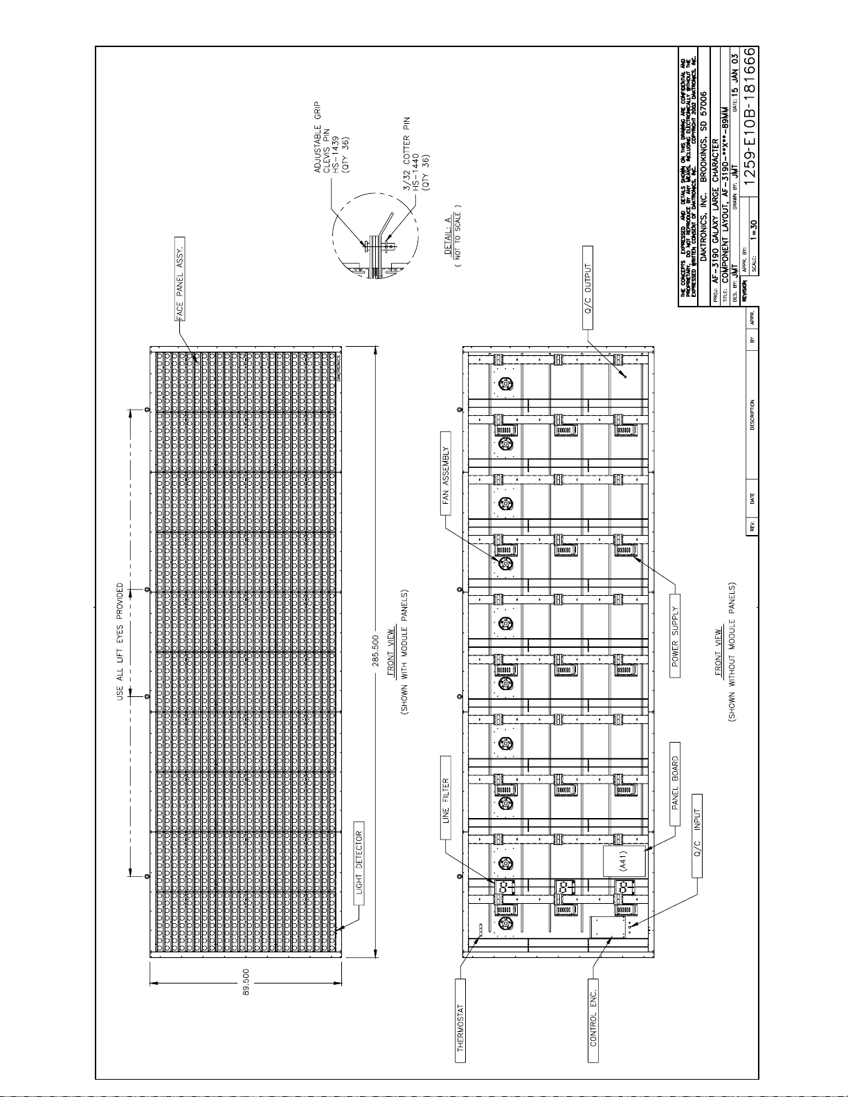
Page 89

Page 90
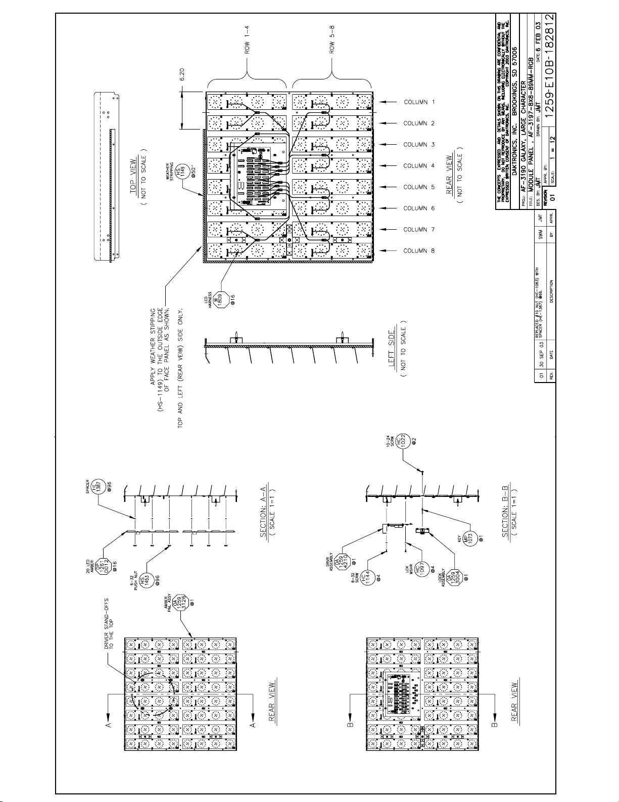
Page 91
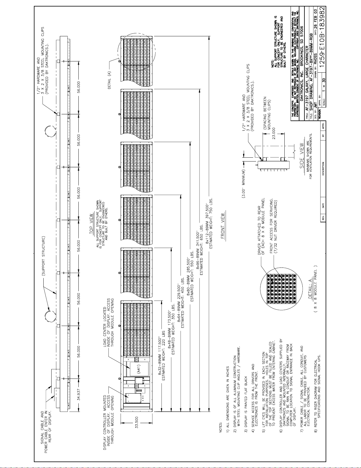
Page 92
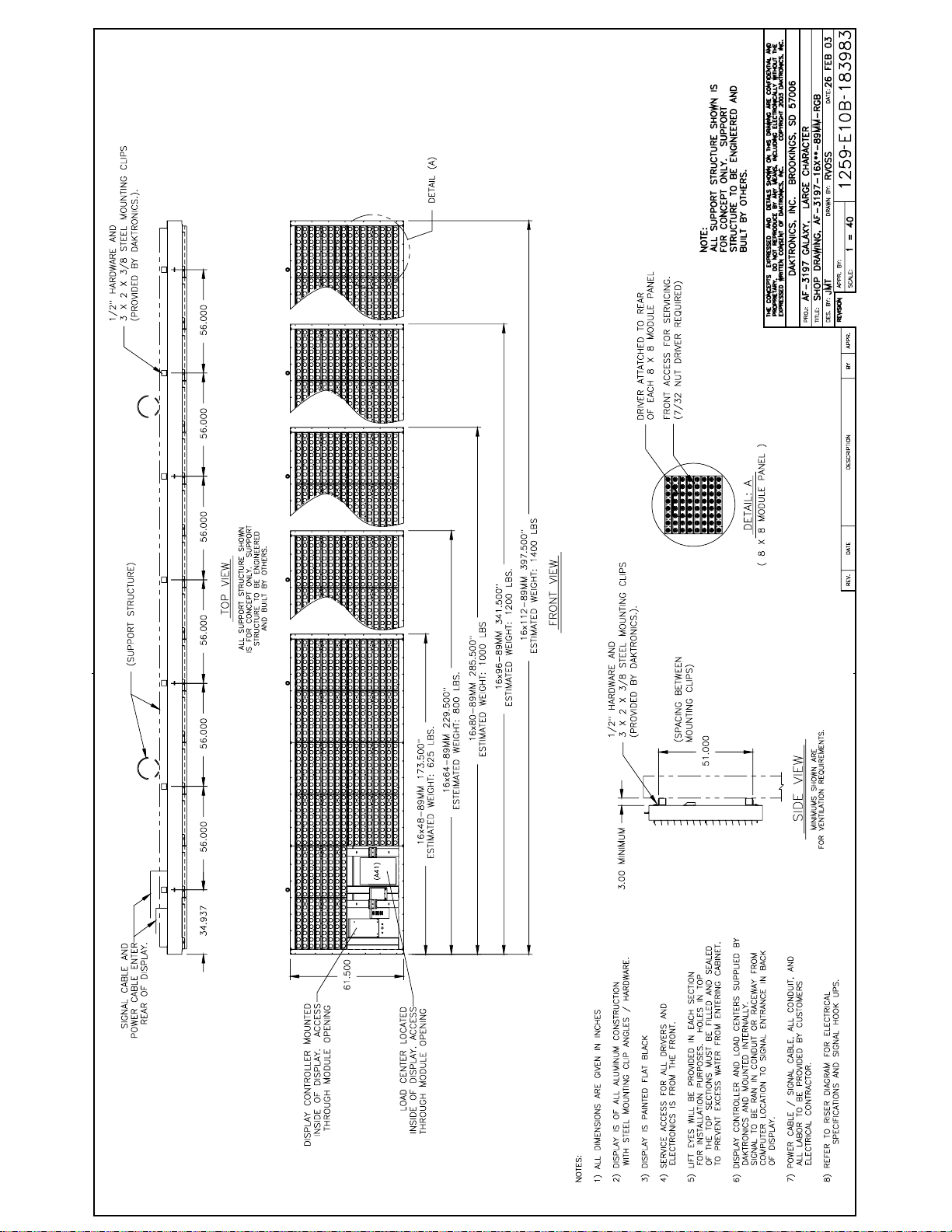
Page 93
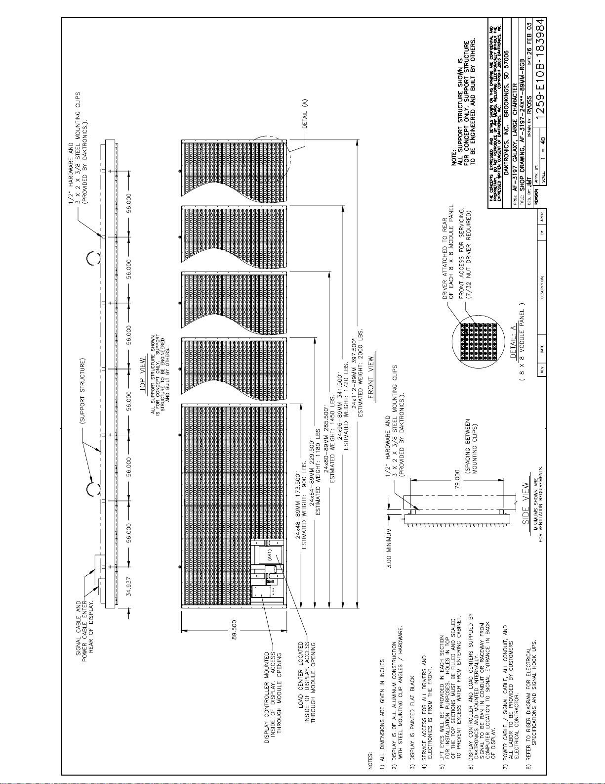
Page 94
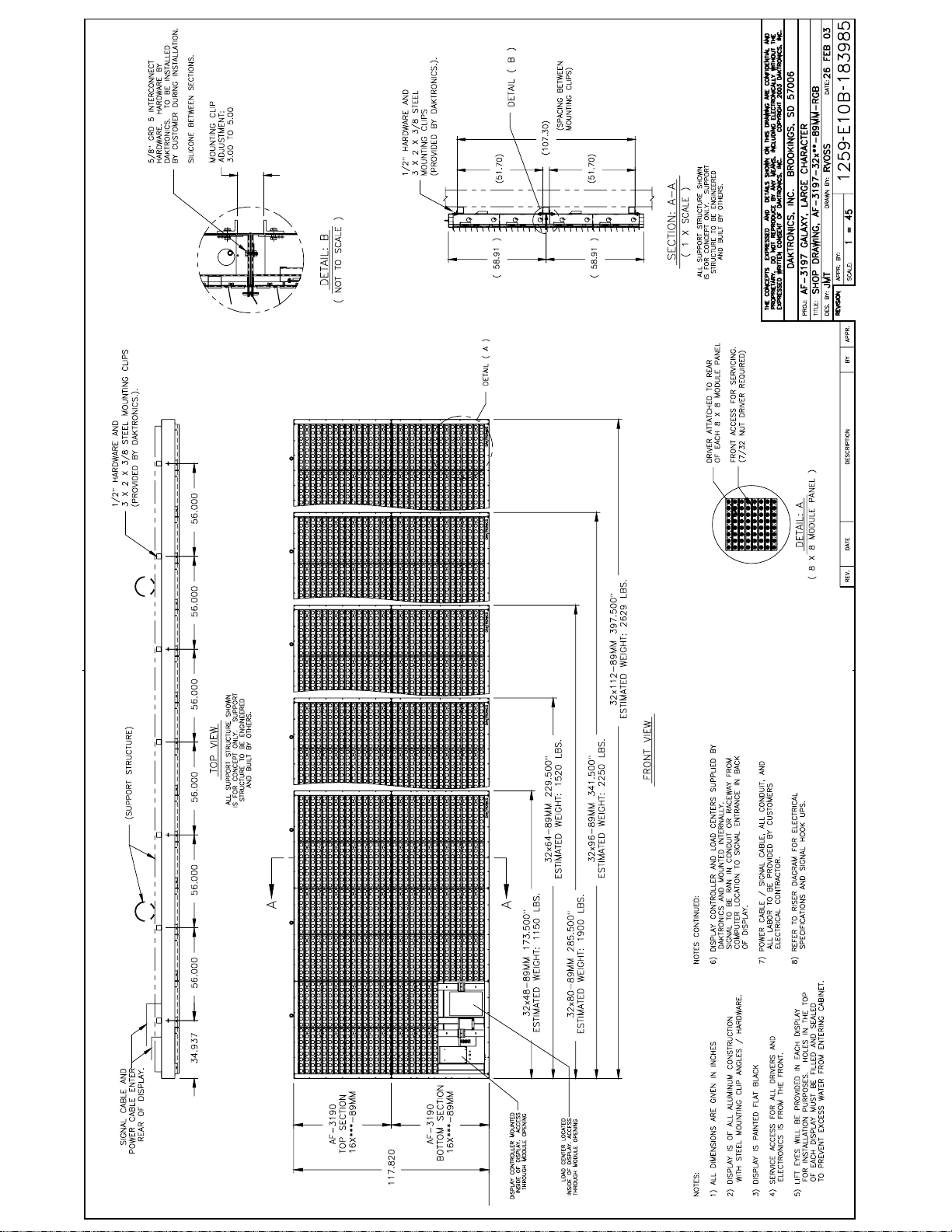
Page 95
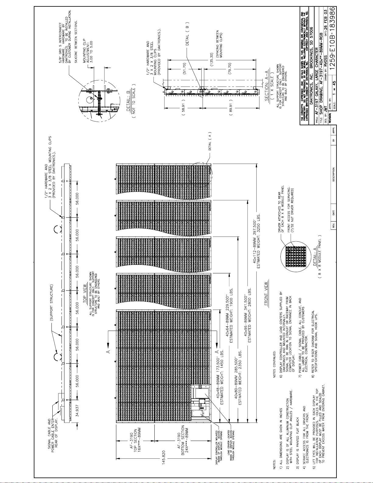
Page 96
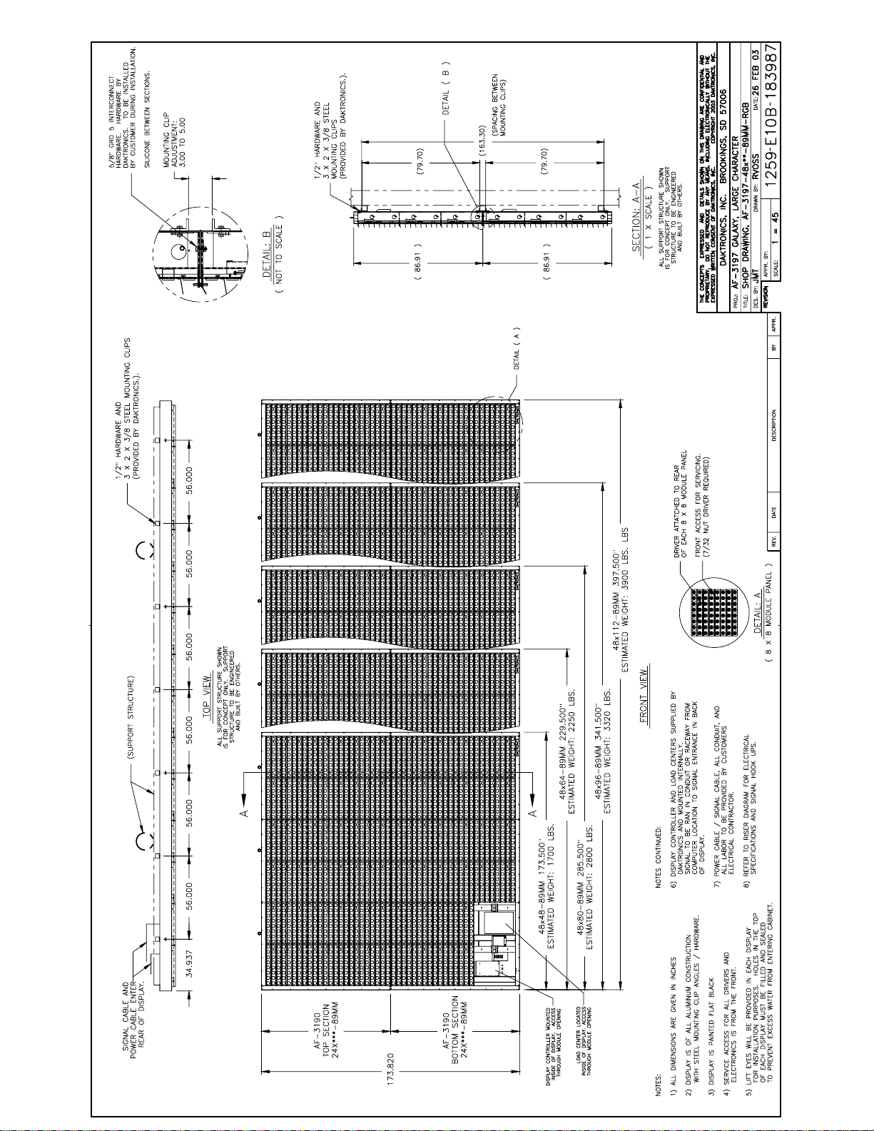
Page 97
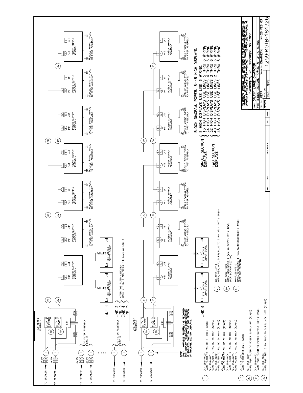
 Loading...