

Page 1
Galaxyä Outdoor 34mm
Louvered LED Displays
Series AF-3065
Installation, Maintenance &
Troubleshooting Manual
ED-12835
All trademarks are the property of their respective companies.
ED-12835
Product #1241
Rev. 1 – 18 September 2001
Copyrightã 2001 Daktronics, Inc.
All rights reserved. While every precaution
has been taken in the preparation of this
manual, the publisher assumes no
responsibility for errors or omiss ions. No part
of this book covered by the copyrights
hereon may be reproduced or copied in any
form or by any means - graphic, electronic,
or mechanical, including photocopying,
taping, or information storage and retrieval
systems - without written permission of the
publisher.
DAKTRONICS, INC.
P.O. Box 5128 331 32nd Ave. Brookings, SD 57006
Phone (605) 697-4034 or (877) 605-1113 Fax 697-4444
www.dak tronics.com e-mail helpdesk@daktronics.com
Page 2

Page 3

Table of Contents
Section 1: Introduction............................................................................................... 1-1
1.1 How to Use This Manual............................................................................................1-1
1.2 Safety Precautions......................................................................................................1-2
1.3 Network Concepts......................................................................................................1-2
RS232 Network....................................................................................................1-3
RS422 Network....................................................................................................1-3
Modem Network..................................................................................................1-3
Fiber Optic Network............................................................................................1-3
1.4 Display Overview.......................................................................................................1-3
RR 1-3
1.5 Component Identification...........................................................................................1-4
1.6 Daktronics Nomenclature...........................................................................................1-6
Section 2: Mechanical Installation............................................................................. 2-1
2.1 Mechanical Installation Overview..............................................................................2-1
2.2 Support Structure Design...........................................................................................2-1
2.3 Ventilation Requirements...........................................................................................2-2
2.4 Lifting the Display......................................................................................................2-2
2.5 Display Mounting.......................................................................................................2-2
2.6 Optional Temperature Sensor Mounting....................................................................2-3
Section 3: Electrical Installation ................................................................................ 3-1
3.1 Common Connectors in the Display...........................................................................3-1
3.2 Control Cable Requirements......................................................................................3-2
RS232 ..................................................................................................................3-2
RS422 ..................................................................................................................3-2
Modem.................................................................................................................3-2
Fiber Optic...........................................................................................................3-2
3.3 RJ Connector Cables..................................................................................................3-3
Installing an RJ Connector...................................................................................3-3
Pin-Outs...............................................................................................................3-3
3.4 Conduit.......................................................................................................................3-4
3.5 Preparing for Power/Signal Connection.....................................................................3-4
3.6 Power..........................................................................................................................3-5
Power Requirements............................................................................................3-5
Grounding............................................................................................................3-5
Power Installation................................................................................................3-5
Power Connection................................................................................................3-6
Main Disconnect..................................................................................................3-7
3.7 Signal Termination from Computer to Display..........................................................3-7
RS232 ..................................................................................................................3-7
RS422 ..................................................................................................................3-7
Modem.................................................................................................................3-8
Fiber Optic...........................................................................................................3-8
3.8 Signal Termination Betwee n Two (or Mo re) Signs ...................................................3-8
Table of Contents
i
Page 4

RS422 Interconnection........................................................................................ 3-8
Fiber Interconnection.......................................................................................... 3-9
3.9 Optional Temperature Sensor Electrical Installation................................................. 3-9
3.10 First Time Turn On.................................................................................................. 3-10
Section 4: Maintenance & Troubleshooting...............................................................4-1
4.1 Maintenance & Troubleshooting Overview............................................................... 4-1
4.2 Signal Summary......................................................................................................... 4-1
4.3 Power Summary......................................................................................................... 4-2
4.4 Service & Diagnostics ............................................................................................... 4-2
Transformer & RFI Filter.................................................................................... 4-3
Controller ............................................................................................................ 4-3
Modules & Drivers.............................................................................................. 4-4
Power Supplies.................................................................................................... 4-5
Light Detector ..................................................................................................... 4-6
Modem ................................................................................................................ 4-6
Fiber Board.......................................................................................................... 4-6
4.5 Ventilation Systems (With Fans and Filters)............................................................. 4-7
4.6 Thermostats................................................................................................................ 4-7
4.7 Weather Stripping...................................................................................................... 4-7
4.8 Display Maintenance................................................................................................. 4-8
4.9 Troubleshooting......................................................................................................... 4-8
4.10 Boot Up Initialization Information ............................................................................ 4-9
4.11 Replacement Parts List.............................................................................................. 4-9
4.12 Daktronics Exchange/Repair & Return Programs................................................... 4-10
Appendix A: Signal Converter....................................................................................... A-1
Appendix B: Reference Drawings ................................................................................. B-1
Page 5

List of Figures
Figure 1: Drawing Label ......................................................................................................................1-1
Figure 2: Controller..............................................................................................................................1-4
Figure 3: Signal Converter (RS232 to RS422 Shown).........................................................................1-5
Figure 4: 8x8 RGB Module (Front and Rear) ......................................................................................1-5
Figure 5: Module Numbering Example – 24x80 Front........................................................................1-6
Figure 6: Module Numbering...............................................................................................................1-6
Figure 7: Typical Label........................................................................................................................1-6
Figure 8: Lifting the Display (Correct, Left; Incorre ct, Rig ht).............................................................2-2
Figure 9: Temperature Sensor Eave/Wall Mount.................................................................................2-3
Figure 10: Temperature Sensor Mounting to Bottom of Display.........................................................2-4
Figure 11: Ribbon Cable Connector.....................................................................................................3-1
Figure 12: Termination Block..............................................................................................................3-1
Figure 13: Phoenix Connector..............................................................................................................3-1
Figure 14: Mate-n-Loc Connector........................................................................................................3-2
Figure 15: RJ11 Connector...................................................................................................................3-2
Figure 16: 6-Conductor RJ-11 Connector and Cable...........................................................................3-3
Figure 17: Flipped Cable with RJ Connectors......................................................................................3-3
Figure 18: Wire with Outer Jacket Stripped.........................................................................................3-3
Figure 19: Installation with Ground and Neutral Conductor Provided................................................3-6
Figure 20: Installation with only Neutral Conductor Provided............................................................3-6
Figure 21: Controller Component Layout............................................................................................4-3
Figure 22: Removing a Module............................................................................................................4-5
Figure 23: Modem................................................................................................................................4-6
Figure 24: Fiber Optic Board...............................................................................................................4-6
Figure 25: Signal Converters...................................................................................................................1
Table of Contents
iii
Page 6

Page 7
Section 1: Introduction
1.1 How to Use This Manual
This manual explains the installation, maintenance and troubleshooting of a Daktronics Galaxy 34mm
louvered LED (light emitting diode) display (series AF-3065). For questions regarding the safety,
installation, operation or service of this system, please refer to the telephone numbers listed on the
cover page of this manual.
The manual is divided into six sections: Introduction, Mechanical Installation, Electrical Installation,
Maintenance & Troubleshooting, and two Appendices.
· Introduction covers the basic information needed to make the most of the rest of this manual.
Take time to read the entire introduction as it defines terms and explains concepts used throughout
the manual.
· Mechanical Installation provides general guidance on display mounting.
· Electrical Installation provides general guidance on terminating power and signal cable at the
display.
· Maintenance & Troubleshooting addresses such things as removing basic display components,
troubleshooting the display, performing general maintenance and exchanging display components.
· Appendix A provides information on the signal converter.
· Appendix B includes the drawings referenced in this manual.
Daktronics identifies manuals by an ED number located on the cover page of each manual. For
example, this manual would be referred to as ED-12835.
Listed below are a number of drawing types commonly used by Daktronics, along with the
information that each is likely to provide. This manual might not contain all these drawings.
· System Riser Diagrams: overall system layout from control computer to display, power and
phase requirements.
· Shop Drawings: fan locations, mounting information, power and signal entrance points and
access method (front and rear).
· Schematics: power and signal wiring for various components.
· Component Placement Diagrams: locations of critical internal display components such as
power supply assemblies, controller boards, thermostats and light detectors.
Figure 1 illustrates Daktronics drawing label. The drawing number is located in the lower-right corner
of the drawing. Drawings in the manual are identified by listing the last set of digits and the letter
preceding them. In the example below, the drawing would be referred to as Drawing A-69945.
Reference drawings are inserted in the Appendix.
Introduction
Figure 1: Drawing Label
1-1
Page 8
All references to drawing numbers, appendices, figures or other manuals are presented in bold
typeface, as shown below.
“Refer to Drawing A-69945 in Appendix B for the power supply location.”
Additionally, drawings referenced in a particular section are listed at the beginning of that section as
seen in the following example:
Reference Drawings:
Component Placement Diagram............................................................Drawing A-69945
Daktronics displays are built for long life, and require little maintenance. However, from time to time,
certain display components will need replacing. The Replacement Parts List in Section 4.11 provides
the names and part number of components that may need to be ordered during the life of the display.
Most display components have a white label that lists the part number. The component part number is
in the following format: 0P-XXXX-XXXX (circuit board) or 0A-XXXX-XXXX (multi-component
assembly).
Following the Replacement Parts List is the Exchange/Replacement Procedure in Section 4.12. Refer
to these instructions if any display component needs replacement or repair.
1.2 Safety Precautions
Important Safeguards:
1. Read and understand these instructions before installing.
2. Be sure the display is properly grounded.
3. Disconnect power when servicing the display.
4. Do not modify the display structure or attach any panels or coverings to the display
without the written consent of Daktronics, Inc.
1.3 Network Concepts
The concept of using LED displays as a cost effective, high impact method of communication is
rapidly growing throughout many industries and businesses. The reasons for this growth are many, but
the need for additional features and complexity of multiple display installations has emerged, and
Daktronics display system have been designed to meet those needs.
The common thread to most client requests is a means of programming and controlling a group of
displays from a central control point. Daktronics responded by developing a power system of
interconnecting and controlling displays. Great care has been taken to design products that will satisfy
a wide variety of installations. Some of the design goals of these systems include the following:
· Easy transfer of messages
· The ability to tell a display or group of displays in the network which message should run
· The ability to determine the status of any display on the network
· The ability to control multiple display technologies on the same network
All that is required for signal installation is standard six (6) conductor modular telephone wire and a
tool to install the connector. Tools required for mounting the display depend on the location and size
of the display. For some installations, it may be possible to buy pre-terminated telephone cables for
use with the displays.
1-2
Introduction
Page 9

There are four (4) network systems available: RS232, RS422, modem and fiber. Up to 240 displays
can exist on one network.
RS232 Network
RS232 (EIA/TIA-232-E) is a standard communication interface that employs a single-ended serial
transmission scheme that uses a maximum cable length of 8 meters (25 feet). This interface was
designed for computer communication at short distances. All computers have an RS232
communications port. Refer to Section 3 for additional information.
RS422 Network
RS422 (EIA/TIA-422-B) is a standard communication interface that utilizes a differential
balanced transmission scheme that uses a typical maximum cable length of 1.2 km (approximately
4000 feet). The main advantage to RS422 over RS232 is the longer cable length that is possible. A
signal converter is needed to convert the computer’s RS232 to RS422. Refer to Section 3 for
additional information.
Modem Network
The modem is a standard communication interface that utilizes standard phone transmission lines.
The phone company assigns each phone line a number that the modem uses to communicate
between controller and display. Refer to Section 3 for additional information.
Fiber Optic Network
A fiber optic network is a standard communication method transmitting light (signal) through a
glass fiber. Fiber optic cable has a maximum length of 2,000 feet. A signal converter is needed to
convert the computers RS232 signal to fiber optic signal; a minimum of two fibers is required.
1.4 Display Overview
Reference Drawings:
Shop Drawing; AF-3065-8-32 High......................................................Drawing B-148418
Shop Drawing; AF-3065-40-48 High....................................................Drawing B-148419
Daktronics AF-3065 Galaxy displays are designed and manufactured for performance, reliability, easy
maintenance and long life. The pixels have a 34mm center-to-center spacing, and are lit using LEDs
(light emitting diodes). Each display section has minimum 9-inch character height. A light sensor on
the front of the display is used for automatic dimming of the LEDs based on the ambient light levels.
The configuration of pixels depends on the model of display ordered.
Refer to the drawings referenced above for the approximate size, weight, and power requirements for
your model of display.
The Galaxy model numbers are described as follows: AF-3065-RRCCC-9-X
AF-3065
RR
CCC
9
X
A typical display system consists of a Windows
software and one or more displays. The displays are offered as single-face units, which are single-
Introduction
= Outdoor 34mm Louvered Galaxy Display
= Number of Rows High (8, 16, 24 and 32 are available)
= Number of Columns Long (48, 64, 80, 96, 112, 128, 144 are available)
= 9” Minimum Character Height
= LED Color (8-color RGB)
â
based personal computer (PC) running Venusâ 1500
1-3
Page 10

sided stand-alone displays. They can become double-faced by mounting them back-to-back with a
second unit.
The Venus 1500 controller is a software package that runs under Windows 98, ME or NT
operating systems on an IBM
â
-compatible computer. Refer to the Venus 1500 controller operator’s
â
4.0 or 2000
manual for installation and operation of the Venus 1500 controller editing station.
Refer to Sections 4.2 and 4.3 for the summaries of how signal and power are routed through the
displays.
1.5 Component Identification
The following illustrations depict some of the more commonly accessed Galaxy display components.
Because Daktronics occasionally alters standard design to meet customer needs, the actual display
design may very slightly from the illustrations below.
This is only a brief overview. Refer to Section 4 for additional information on maintaining the
various display components.
Com Port: A COM port is a connector on the back of the control computer. The COM port is used to
control the display network through either a 9- or a 25-pin serial connector.
Controller: The display’s controller is the “brains” of the display (refer to Figure 2). The controller
receives signal information from the control computer, translates it, and activates the appropriate
pixels on the display accordingly.
Figure 2: Controller
Galaxyä: Daktronics trademarked name for LED monochrome, tri-colored or RGB matrix displays.
Network: A network consists of multiple displays connected to each other. Up to 240 displays can
exist on one network.
1-4
Introduction
Page 11
Power Supply: converts AC line voltage from the load center to low DC voltage for one or more
module driver boards.
RS232: RS232 is a standard PC communication type with a maximum cable length of 25 feet (7.62
meters).
RS422: RS422 is a standard differential communication type with a maximum cable length of 4000
feet (1.2 kilometers).
Display Address: The display address is an identification number
assigned to each display of a network. It is set by flipping DIP switches
on the controller. The control software uses the address to locate and
communicate with each display. Displays that are on the same network
cannot have the same address.
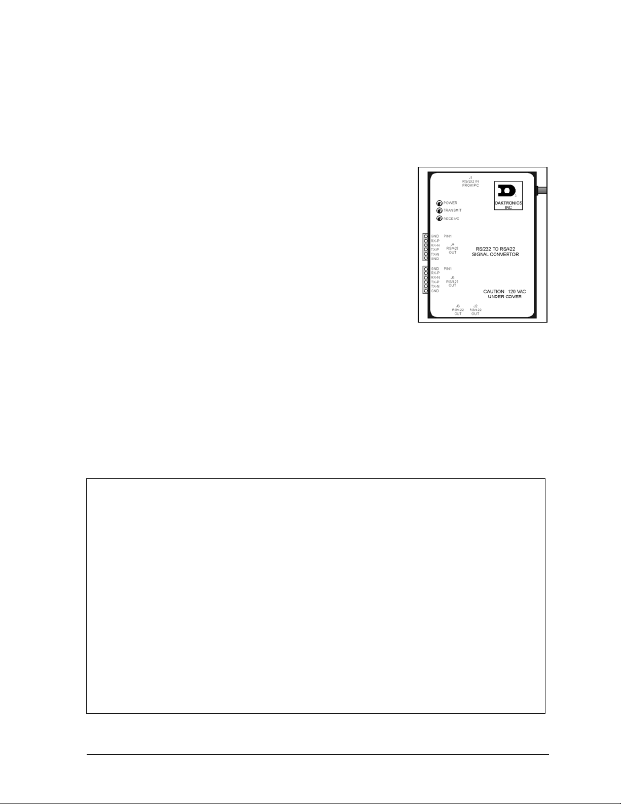
Signal Converter: The signal converter, shown in Figure 3, is a
Daktronics supplied unit that converts the data from RS232 to RS422,
or RS232 to fiber optic signal. The signal converter is connected to the
control PC via straight through serial cable.
Refer to Figure 3 and Figure 4 while reading the following component
descriptions.
Figure 3: Signal Converter
(RS232 to RS422 Shown)
Driver/Pixel Board: The LED pixels are mounted directly onto the
driver/pixel board. This board is also responsible for the switching and intensity levels of the LEDs.
LED (light emitting diode): low energy, high intensity lighting units.
Louver: a black plastic shade positioned horizontally above each pixel row. The louvers increase the
level of contrast on the display face and direct LED light.
Module: 34mm Galaxy modules are 8 pixels high by 8 pixels wide. Each is individually removable
from the front of the display.
Figure 4: 8x8 RGB Module (Front and Rear)
Introduction
1-5
Page 12
Module Latch Assembly: device utilizing a rotating retainer bar to hold the module firmly to the
display frame. There are two per module: one near the top and one near the bottom. Use a c² Allen
wrench to turn the retaining bar.
Pixel: a cluster of LEDs. The number and color of the LEDs depends on display application.
1.6 Daktronics Nomenclature
To fully understand some
Daktronics drawings, such as
schematics, it is necessary to
know how various components
are labeled in those drawings.
This information is also useful
when trying to communicate
maintenance or troubleshooting
efforts.
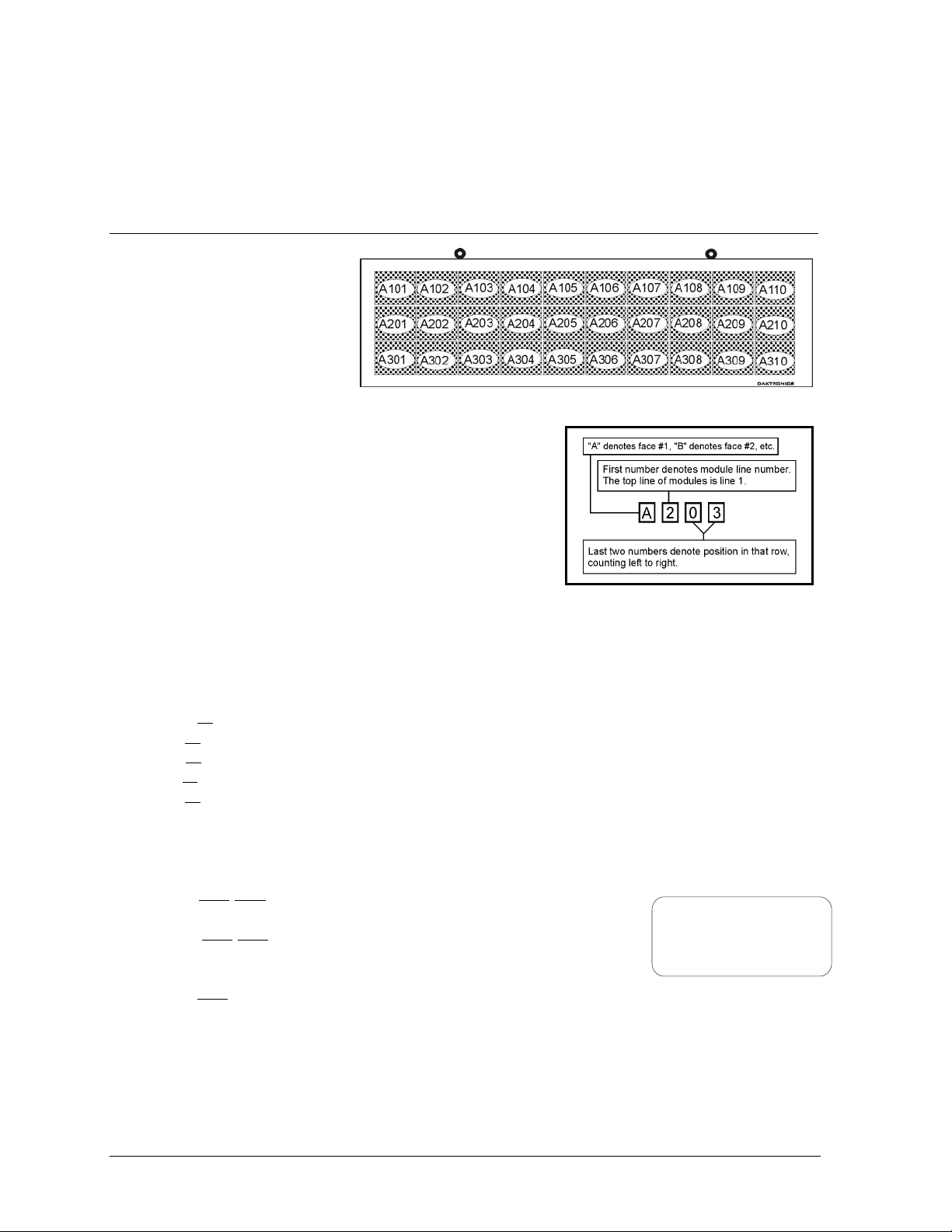
A module is the building block of the Galaxy display. Each
module measures 8 pixels high by 8 pixels wide. By placing
modules side-by-side and on top of one another a display of any
size can be designed and built. Individual modules can be easily
removed from the display if required. Figure 5 illustrates how
Daktronics numbers modules on a Galaxy display. Figure 6
breaks down the module numbering method.
The label “A” on a drawing typically denotes an assembly. An assembly can be a single circuit board
or a collection of components that function together, usually mounted on a single plate or in a single
enclosure. Assemblies are divided into two types: those that route signal and those that route power.
In addition, the following labeling formats might be found on various Daktronics drawings:
· “TB??” denotes a termination block for power or signal cable.
· “F??” denotes a fuse.
· “E??” denotes a grounding point.
· “J??” denotes a power or signal jack.
· “P??” denotes a power or signal plug for the opposite jack.
Finally, Daktronics part numbers are commonly found on drawings. Those part numbers can be used
when requesting replacement parts from Daktronics C ustom er Service. Take note of the following part
number formats.
· “0P-????-????” denotes an individual circuit board, such as a line
receiver.
· “0A-????-????” denotes an assembly, such as a circuit board and
the plate or bracket to which it is mounted. A collection of circuit
boards working as a single unit may also carry an assembly label.
· “W-????” denotes a wire or cable. Cables may also carry the
assembly numbering format in certain circumstances. This is especially true of ribbon cables.
Most circuit boards and components within this display carry a label that lists the part number of the
unit. If a circuit board or assembly is not listed in the replacement parts list in Section 4, use the label
to order a replacement. A typical label is shown in Figure 7. The part number is in bold.
Figure 5: Module Numbering Example – 24x80 Front
Figure 6: Module Numbering
0P-1195-0001
SN: 6343
05/19/99 REV.1
Figure 7: Typical Label
1-6
Introduction
Page 13

Section 2: Mechanical Installation
LNotes: Daktronics does not guarantee the warranty in situations where the display is not constantly
in a stable environment.
Daktronics engineering staff must approve any changes that may affect the weather-tightness of the
display. If any modifications are made, detailed drawings of the changes must be submitted to
Daktronics for evaluation and approval, or the warranty may be void.
Daktronics is not responsible for installations or the structural integrity of support structures done by
others. It is the customer’s responsibility to ensure the structure and any additional hardware have
been approved by a qualified structural engineer.
2.1 Mechanical Installation Overview
Because every installation site is unique, there is no single Daktronics-approved procedure for
mounting the Galaxy displays. The information contained in this section is general information only
and may or may not be appropriate for your particular installation.
A qualified individual must make all decisions regarding the mounting of this display.
Read both the mechanical and electrical installation sections of this manual before beginning
any installation procedures.
2.2 Support Structure Design
Support structure design depends on the mounting methods, display size and weight. The structure
design is critical and should be done only by a qualified individual. Display height and wind loading
are also critical factors. It is the customer’s responsibility to ensure that the structure and mounting
hardware are adequate. Daktronics is not responsible for the installations or the structural integrity of
support structures done by others.
It is the installer’s responsibility to ensure the mounting structure and hardware are capable of
supporting the display, and will agree with local codes.
Before beginning the installation process, verify the following.
· The mounting structure will provide a straight and square mounting frame for the display.
· The mounting structure is capable of supporting the display and will not yield at any
unsupported points after mounting.
· Clearance: 3² of unobstructed space is available below the display for filter removal from the
display. 1-¼² of unobstructed space is available above the top of the display.
Correct any deficiencies before installation.
Mechanical Installation
2-1
Page 14
2.3 Ventilation Requirements
Reference Drawings:
Shop Drawing; AF-3065-8-32 High......................................................Drawing B-148418
Shop Drawing; AF-3065-40-48 High....................................................Drawing B-148419
Fans are mounted in the bottom of the display and to the back sheet for ventilation. Maintain a
minimum distance of 3² (7.62cm) below the display to maintain proper airflow. Refer to the
appropriate shop drawing for additional information.
If the display cabinet is completely enclosed:
· 6 square inches of unobstructed opening per module must be provided to ensure adequate
cooling.
· Allowances must be made to compensate for the percentage of material covering the openings
in the structure.
· For adequate cooling, forced ventilation may be required. If air is forced into the enclosed
cabinet, 10 cubic feet per minute must be provided per module (10.6² x 10.6² active area).
If these requirements are not met, the Galaxy display warranty may be void.
2.4 Lifting the Display
The top of the larger displays is equipped with eyebolts that are used to lift the unit. Take special care
to ensure that the rated load of the eyebolts is not exceeded. Refer to the information at the end of this
section labeled Eyebolts to determine the allowable load of the eyebolts shipped with the display.
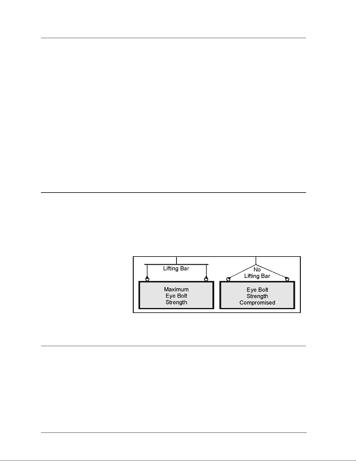
Figure 8 illustrates both the correct (left example) and the incorrect (right example) method of lifting
a display. Lift the display as shown on the left, with the lifting bar. Use every lifting point provided!
Do not attempt to permanently
support the display by the
eyebolts.
If removing the eyebolts,
adequately seal the holes using
½-13 bolts and sealing washers
and silicone along the threads.
This ensures that water does
Figure 8: Lifting the Display (Correct, Left; Incorrect, Right)
not enter the display.
2.5 Display Mounting
Reference Drawings:
Mtg Clip Angles; AX-XXXX-40/48XX-34B............................................Draw i ng A-128799
Mtg Clip Angles AX-XXX-8/32XX-34B.................................................Drawi ng A-128801
Shop Drawing; AF-3065-8-32 High......................................................Drawing B-148418
Shop Drawing; AF-3065-40-48 High....................................................Drawing B-148419
The method used to mount displays can vary greatly from location to location. For this reason, only
general mounting topics can be addressed in this manual.
2-2
Mechanical Installation
Page 15
It is the responsibility of the installer to ensure the installation will adequately meet local codes
and standards. The mounting hardware and method is also the responsibility of the installer.
Before beginning the installation process, verify the following items.
· The mounting structure will provide a straight and square mounting frame for the display. Height
variation in any four-foot horizontal section may not exceed ¼-inch.
· The mounting structure will not give way at any unsupported points after the display is mounted.
The back of the display is equipped with 2 x 2 x ¼² steel clip angles at the locations shown in
Drawings A-128799 and A-128801. These angles may be used for mounting purposes. Remember to
have all mounted displays inspected by a qualified structural engineer. It is the customer’s
responsibility to determine the proper wall mounting method and location.
Refer to Drawing A-128799 for a suggested wall mount method. The number of attachment points
needed and the wall structure must be reviewed by a qualified structural engineer and meet all national
and local codes. Daktronics recommends using all clip angles as attachment points.
1. Carefully uncrate the display. Look each side of the display over for damage during shipping.
2. Following the guidelines described in Section 2.4, lift the display into position on the support
structure.
3. Weld or use ½² Grade-5 bolts and hardware to secure the clip angles to the support structure as
shown in Detail A in Drawing A-128799.
4. Refer to Section 3 for information on routing power and signal.
5. After installation is complete, carefully inspect the display for any holes that may allow water to
seep into the display. Seal any openings with silicone. If the eyebolts on the top of the display
have been removed, plug the holes with bolts and the rubber sealing washer that was removed
with the eyebolt.
2.6 Optional Temperature Sensor Mounting
The optional temperature sensor is mounted
separately and requires a location away from
the influence of chimneys, air conditioners,
vents, tar roofs, concrete and parking lots
which can cause abnormal temperature
fluctuations. Usually a separation of at least 20
to 30 feet horizontally and eight feet vertically
is required to achieve this. Locations where air
movement is restricted are also unsatisfactory.
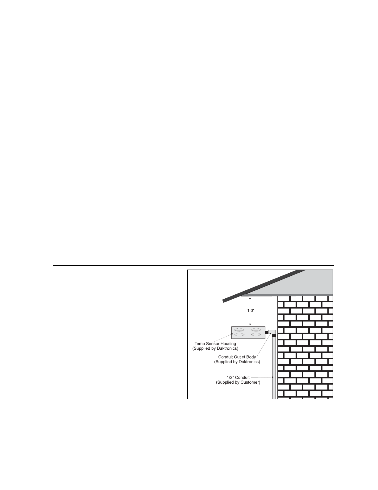
A first-choice temperature sensor location is a
north eave or northern exposure away from
direct sun light and above grass. This location
gives extra stability and accuracy to the sensor
because of the added shading usually obtained
on a northern exposure. There should be at
least one foot between the bottom of the eave
and the top of the temperature sensor housing
for accurate readings, as seen in Figure 9.
Due to the nature of the signal cable used to send the temperature information, the maximum distance
between the temperature sensor and the display is 1,000 feet (304.8 meters).
Figure 9: Temperature Sensor Eave/Wall Mount
Mechanical Installation
2-3
Page 16
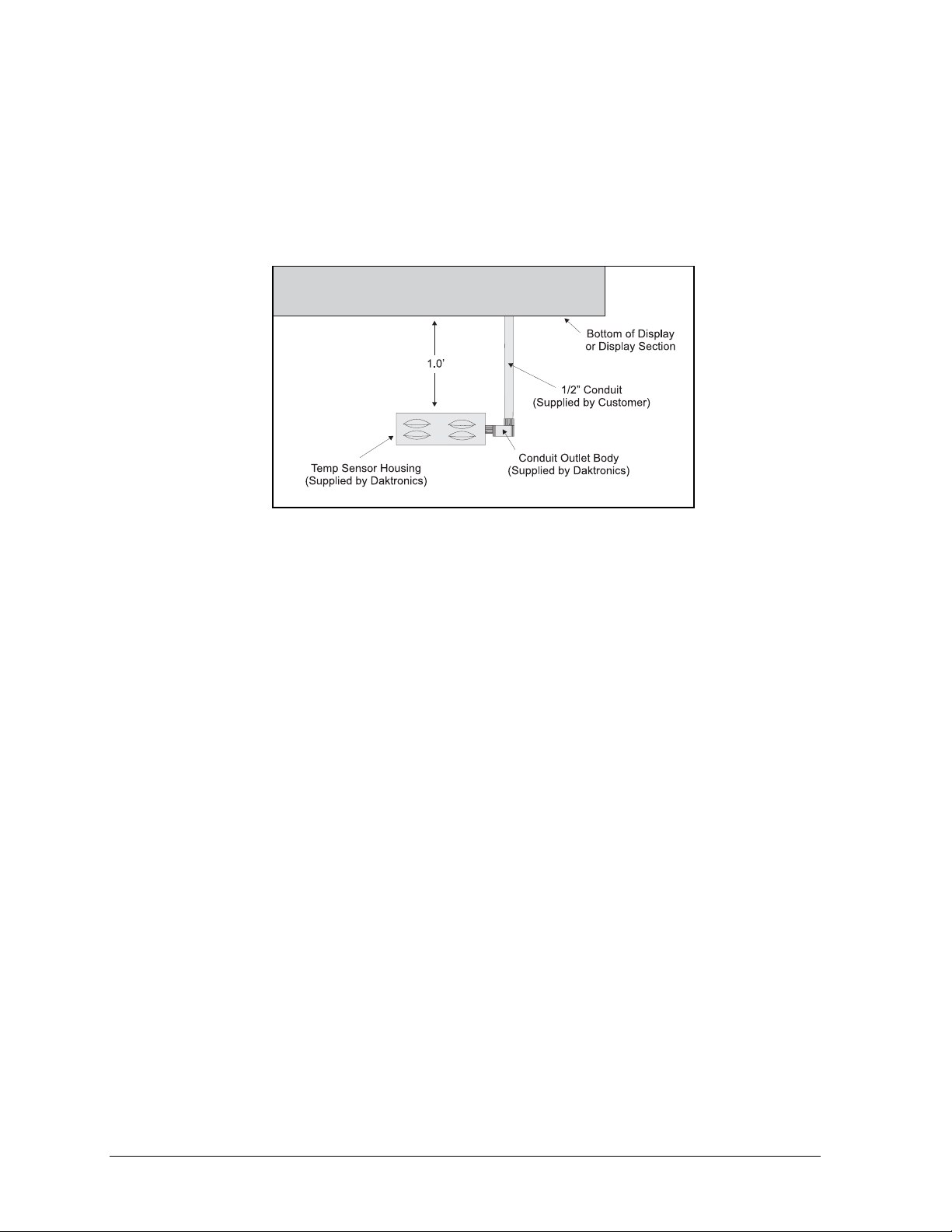
The second choice for locating a temperature sensor is on the display itself, or somewhere on the
display structure. A light-colored display is preferred in this application. Location of the sensor should
be above, below, or on a northern edge to try to keep the sensor shaded. If mounting above the
display, a minimum height above of six feet is required. If mounting below the display, a minimum of
eight feet above ground and a minimum of one foot between sensor and display are required, as seen
in Figure 10. Greater accuracy is obtained if there is grass below the display rather than concrete or
some other material.
Refer to Section 3.9, Optional Temperature Sensor Electrical Installation for wiring instructions.
Figure 10: Temperature Sensor Mounting to Bottom of
Display
2-4
Mechanical Installation
Page 17
Section 3: Electrical Installation
Only a qualified individual should terminate power and signal cable within this Daktronics display!
The Daktronics engineering staff must approve ANY changes made to the display. Before altering the
display, submit detailed drawings for the proposed modifications to the Daktronics engineering staff
for evaluation and approval or the warranty will be rendered null and void.
3.1 Common Connectors in the Display
The power and signal connections in the displays use many different types of
connectors. Take special care when disengaging any connector so as not to
damage the connector, the cable or the circuit board.
When pulling a connector plug from a jack, do not pull on the wire or
cable; pull on the jack itself. Pulling on the wires may damage the
connector.
The following information presents some common connectors encountered
during display installation and maintenance.
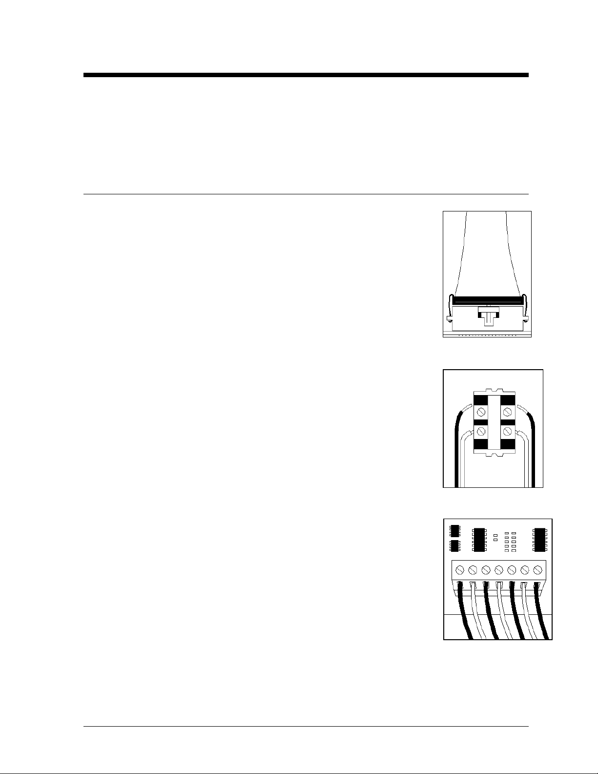
1. Ribbon Cable Connectors:
Figure 11 illustrates a typical ribbon connector. To disconnect the ribbon cable,
push the metal clips on the sides to unlock and remove the jack.
Before replacing a ribbon cable connector, spray it with DeoxitJ contact cleaner
to remove any foreign matter that may cause signal problems. In addition, apply
a generous amount of Cal-LubeJ protector paste to the plug before inserting it
into the jack. This paste will protect both the plug and the jack from corrosion.
2. Termination Blocks:
Termination blocks are usually used to connect internal power and signal wires
to wires of the same type coming into the display from an external source. Power
wires need to have one-half inch of insulation stripped from the end of the wire
prior to termination. Tighten all screws firmly to ensure a good electrical
connection. Refer to Figure 12.
3. Phoenixä-Style Connectors:
Phoenix-style connectors, which are usually green, are often used for signal
termination on circuit boards. Refer to Figure 13. Strip one-quarter inch of
insulation from the wire prior to termination. To remove a wire, turn the above
screw counter-clockwise to loose the connectors grip on the wire. To insert a
wire, push the bare wire into the connector and turn the above screw clockwise
to lock the wire into place.
Figure 11: Ribbon
Cable Connector
Figure 12:
Termination Block
Figure 13: Phoenix
Connector
Electrical Installation
3-1
Page 18
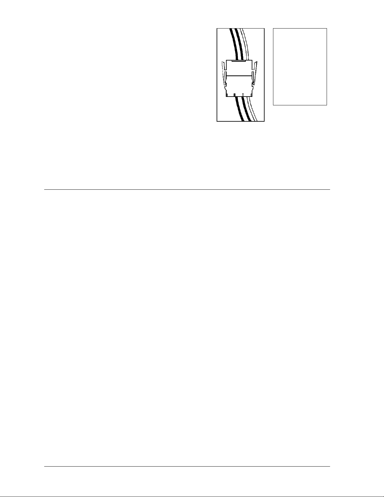
4. Mate-n-Lokä Connectors:
The Mate-n-Lok connectors found in the displays are white
and come in a variety of sizes. Figure 14 illustrates a fourpin Mate-n-Lok connector. To remove the plug form the
jack, squeeze the plastic locking clasps on the side of the
plug and pull it from the jack.
5. Phone Jacks (RJ11 Connectors):
RJ connectors, as seen in Figure 15, are similar to the
telephone connectors found in homes and are used on the
ends of flat RJ11 cable. In order to remove this plug from
the jack, depress the small clip on the underside of the plug.
Before replacing an RJ connector, spray it with Deoxit
™
Figure 14: Maten-Loc Connector
Figure 15: RJ11
Connector
contact cleaner to remove any foreign matter that may cause signal problems. In addition, apply a
generous amount of Cal-Lube protector paste to the plug before inserting it into the jack. This paste
will protect both the plug and the jack from corrosion.
3.2 Control Cable Requirements
RS232
This cable is a 2-conductor shielded cable used to transmit an RS232 signal (Daktronics part
number W-1117). This shielded cable should not be subjected to mechanical flexing after
installation. This cable is not for direct burial and should be routed in a dedicated, grounded
metallic conduit at the base of the sign structure. This cable has a maximum length of 25 feet.
RS422
This cable is a 6-conductor shielded cable used to transmit an RS422 signal (Daktronics part
number W-1210). This shielded cable consists of unpaired wires. They should not be subjected to
mechanical flexing after installation. This cable is not for direct burial and should have one of the
following routings:
· In dedicated metallic conduit
· Inside buildings - if cable is not in conduit, keep away from interference signals.
LWith interference signals (such as power conductors, intercom, etc.) typically a two foot
separation is required. The maximum length of an RS422 signal cable is 4,000 feet (1.22 km).
Modem
The modem option will use standard telephone cable routed through conduit. The local telephone
company will need to assist in this installation.
Ask the telephone company which colors are used by the TIP, and the RING for signal hook up.
Note: The telephone lines must be dedicated lines and not run through a switch
board/communications system.
Fiber Optic
This cable is a 4-fiber cable (Daktronics part number W-1376). Two fibers are used for display
communications and the other two are saved for spares. The cable may be either direct burial or
routed in conduit but it should not be subjected to mechanical flexing. The maximum length of a
fiber optic cable is 2,000 feet (611.6 meters).
3-2
Electrical Installation
Page 19
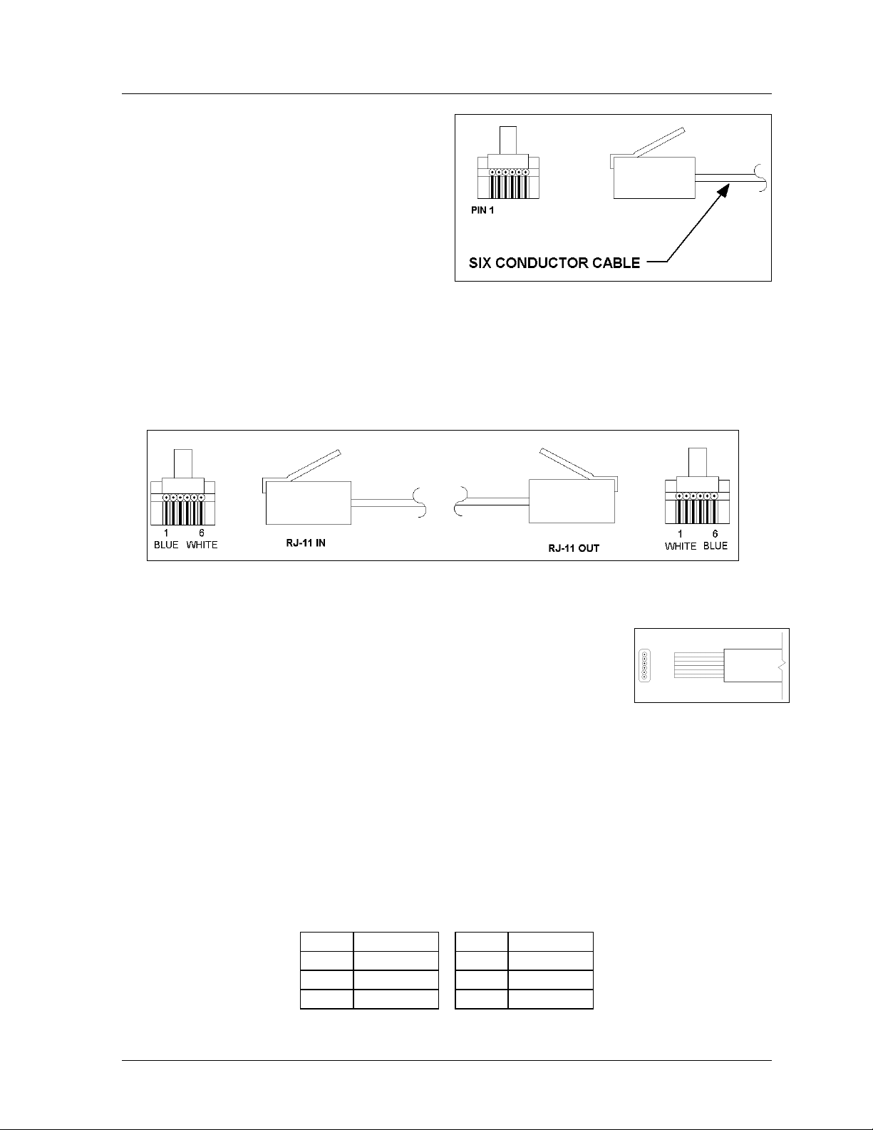
3.3 RJ Connector Cables
The conductor connector used in the network is an
industry standard, 6-pin RJ11. This connector can
be found on many telephones and LANs.
The cable used in the network is a standard flat
six conductor telephone cable (standard flipped
cable). Refer to Figure 16. This cable has one end
that is the mirror image of the other end (i.e. the
cable is flipped). Refer to Figure 17 for a
standard flipped cable.
Notice in Figure 17 that the color code on one connector must be made the opposite on the other
connector. When installing a network, it is not easy to remember in which direction the previous end
was oriented. One simple way to avoid confusion is to standardize the color code, having one color for
the connector going into the output of a sign and the opposite color for a connector going into the
input of a sign. This will help ensure correct cabling since cables are always installed from the output
jack of one sign to the input jack of the next sign.
Figure 16: 6-Conductor RJ-11 Connector and Cable
Figure 17: Flipped Cable with RJ Connectors
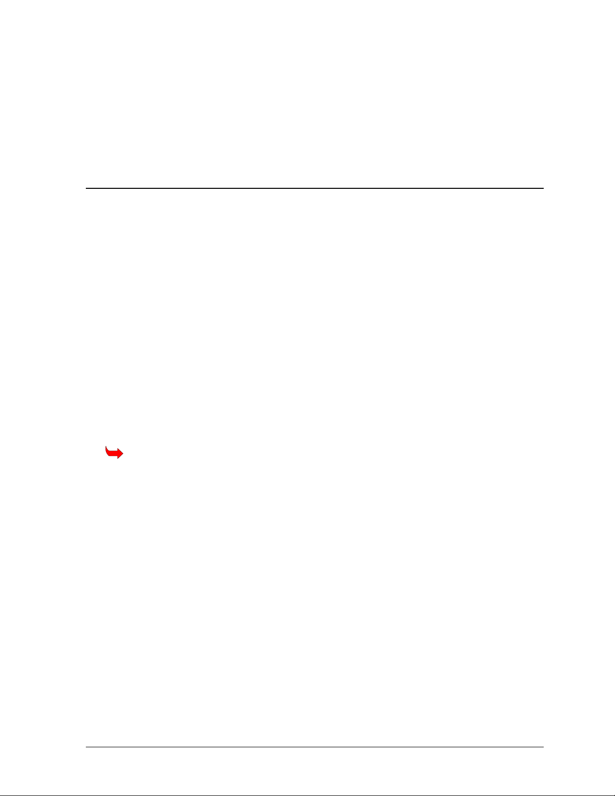
Installing an RJ Connector
Installing an RJ connector on the end of the conductor cable is a simple
task when the correct tools are used. The RJ crimping tool (Daktronics part
number TH-1033) performs two separate steps.
First, use the crimping tool to strip the outer insulation from the inner
wires. This does not result in bare wires since only the gray outer jacket is
removed. After correct stripping, the wire will appear as shown in Figure 18.
The crimping tool is then used to crimp the RJ connector onto the cable. The RJ connector is
locked into a special socket in the tool. The stripped wire is inserted into the RJ connector.
Finally, the tool is squeezed like a pliers to crimp the connector onto the wire. This completes the
installation of an RJ connector onto the wire.
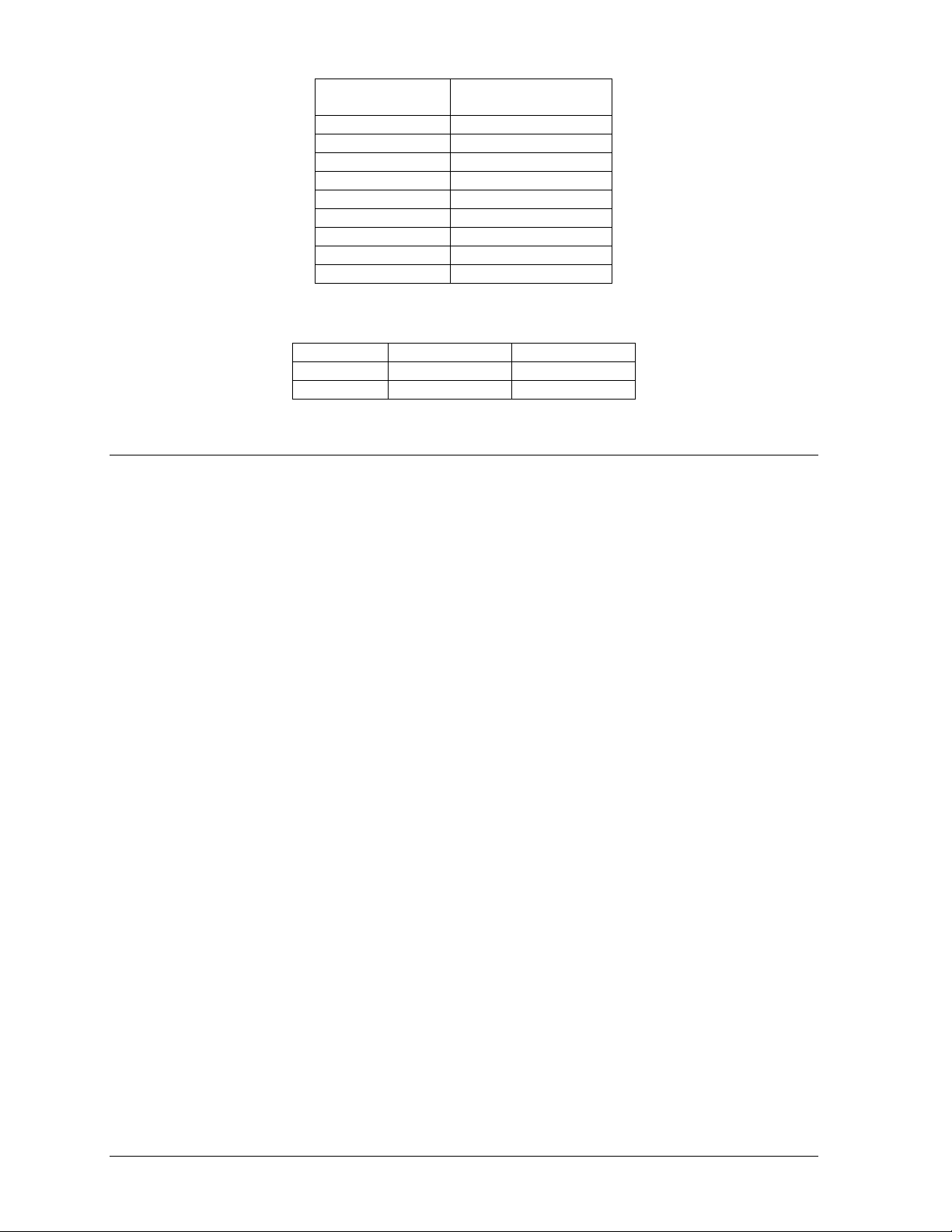
Pin-Outs
The RS422 jack’s pin out is as follows:
RJ11 Function RJ11 Function
1 GROUND 4 D1IN-P
2 D1OUT-P 5 D1IN-N
3 D1OUT-N 6 GROUND
Figure 18: Wire with
Outer Jacket Stripped
Electrical Installation
3-3
Page 20

3.4 Conduit
Reference Drawings:
System Riser Diagram, RS232..............................................................Drawing A-96058
System Riser Diagram, RS422..............................................................Drawing A-92681
System Riser Diagram, Modem............................................................. Drawing A-88426
System Riser Diagram, Fiber .............................................................. Drawing A-110559
Signal Input, Venus 1500 .................................................................... Drawing A-129110
Entrance Box 8/16...............................................................................Drawing A-149160
Assy, Power Box 2/4........................................................................... Drawing A-155736
Shop Drawing; AF-3065-8-32 High......................................................Drawing B-148418
Shop Drawing; AF-3065-40-48 High....................................................Drawing B-148419
Daktronics does not include the conduit. Refer to Drawings B-148418 and B-148419 for approximate
locations for power and signal conduit. Separate conduit must be used to route:
· Power
· Signal IN wires
· Signal OUT wires (if signal is required for another display)
Knockout holes for ½² conduit are located at the bottom right (rear view) of the back of the display
(refer to Drawings B-148418 and B-148419).
LFor displays with more than one face, signal and temperature sensor wiring between displays can
be routed through the same conduit.
3.5 Preparing for Power/Signal Connection
Reference Drawings:
System Riser Diagram, RS232..............................................................Drawing A-96058
System Riser Diagram, RS422..............................................................Drawing A-92681
System Riser Diagram, Modem............................................................. Drawing A-88426
System Riser Diagram, Fiber .............................................................. Drawing A-110559
Signal Input, Venus 1500.................................................................... Drawing A-129110
Entrance Box 8/16...............................................................................Drawing A-149160
Power Connection, AF-306X............................................................... Drawing A-154965
Assy, Power Box 2/4........................................................................... Drawing A-155736
Shop Drawing; AF-3065-8-32 High......................................................Drawing B-148418
Shop Drawing; AF-3065-40-48 High....................................................Drawing B-148419
Detail drawing, Controller and Power Term 24-48 High.......................Drawing B- 156686
Component Layout Diagram...........................................................................Appendix B
Schematic...................................................................................................... Appendix B
1. Punch or use f² (0.875) conduit holes for the desired conduit openings. Be careful that none of
the internal components are damaged. Refer to Drawings B-148418 and B-148419. Attach the
conduit.
2. Remove the bottom left two modules (AX01 and AX02) to expose the power enclosure and signal
panel. To do this, use a nut driver or c² Allen wrench to turn the latch access fasteners one-
quarter turn. Turn the top latch clockwise and the bottom latch counter-clockwise. Lift each
module away from the display; reach behind it and disconnect all power and signal connections.
3. Locate the controller and power termination box for these displays in the Component Layout
Diagram. The controller is shown in Figure 2. The controller receives the incoming signal and
relays it to the individual modules.
3-4
Electrical Installation
Page 21
4. Route power to the display through a fused disconnect switch capable of opening all ungrounded
power conductors. Install this disconnect within the line of sight of any personnel performing
maintenance on the display. If the disconnect is located out of sight of the display, it must be
capable of being locked in the open position.
5. Power conductors from the disconnect to the display should be routed through conduit in
agreement with local code.
6. You may route the signal cable from the control computer to the display at this time also. Be sure
to run the power and signal cables in a separate conduit.
3.6 Power
Reference Drawings:
Power Specs, 8x144 Display RGB ...................................................... Drawing A-148571
Entrance Box 8/16...............................................................................Drawing A-149160
Assy, Power Box 2/4...........................................................................Drawing A-155736
Power Connection, AF-306X...............................................................Drawing A-154965
Schematic......................................................................................................Appendix B
Power Requirements
Refer to Drawing A-148571 for voltage and current requirements for your display size. Each uses
a 120VAC or 120/240 VAC single-phase power source. Depending on the module color and
display size the power supply may vary.
Do not connect the displays to any voltage other than that listed on the Daktronics product label.
Proper power installation is imperative for proper display operation. The following sub-sections
give details of display power installation.
Grounding
Displays MUST be grounded according to the provisions outlined in Article 250 of the
National Electrical Code
The display system must be connected to earth-ground. Proper grounding is necessary for reliable
equipment operation. It also protects the equipment from damaging electrical disturbances and
lightning. The display must be properly grounded or the warranty will be void.
The material of an earth-ground electrode differs from region to region and from conditions
present at the site. Consult the National Electrical Code and any local electrical codes that may
apply. The support structure of the display cannot be used as an earth-ground electrode. The
support is generally embedded in concrete, and if in earth, the steel is either primed or it corrodes,
making it a poor ground.
Power Installation
There are two considerations for power installation; installation with ground and neutral
conductors provided and installation with only a neutral conductor provided. These two power
installations differ slightly, as described in the following paragraphs:
Installation with Ground and Neutral Conductors Provided
For this type of installation, the power cable must contain an isolated earth-ground conductor.
Under this circumstance, do not connect neutral to ground at the disconnect or at the display.
This would violate electrical codes and void the warranty. Use a disconnect so that all hot
Electrical Installation
®
. Daktronics recommends a resistance to ground of 10 ohms or less.
3-5
Page 22
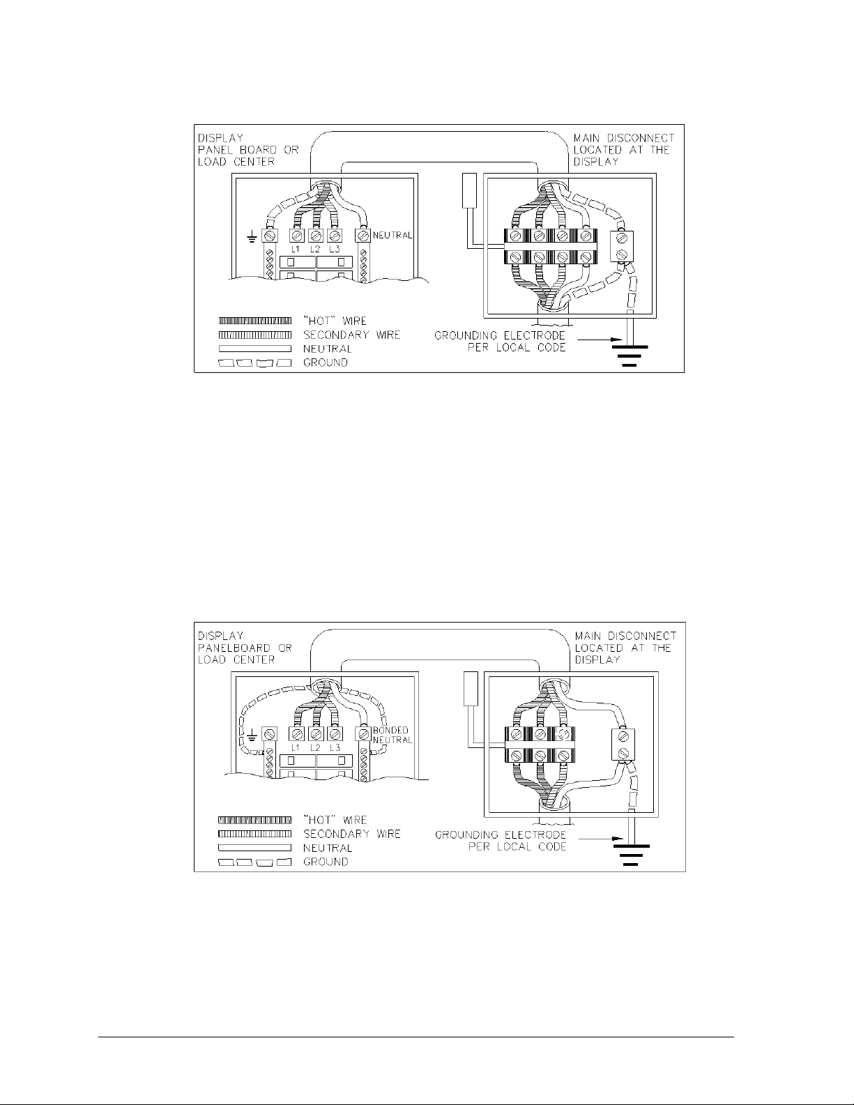
lines and neutral can be disconnected. Refer to Figure 19 for installation details. The National
Electrical Code requires the use of a lockable power disconnect within sight of or at the sign.
Figure 19: Installation with Ground and Neutral Conductor Provided
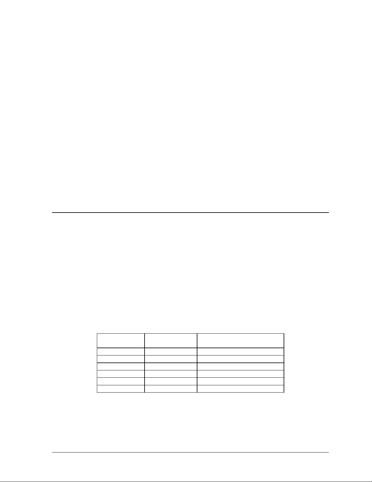
Installation w ith Only a Neutral Conductor Provided
Installations where no grounding conductor is provided must comply with article 250-32 of
the National Electrical Code. If the installation in question meets all of the requirements of
article 250-32, the following guidelines must be observed:
· Connect the grounding electrode cable at the local disconnect, never at the sign
panelboard.
· A disconnect that opens all of the ungrounded phase conductors should be used.
· The neutral and the ground conductors should be bonded in the sign panelboard.
Refer to Figure 20 for installation details.
Figure 20: Installation with only Neutral Conductor Provided
Power Connection
Incoming power is connected within the power termination enclosure. Complete the following
steps to terminate the hot and neutral wires at the termination block within the enclosure. Refer to
Drawing A-149554 and the appropriate schematic for your display size.
1. Access the enclosure by removing the left bottom two modules as described in Section 3.5.
3-6
Electrical Installation
Page 23
2. Route the power cables through the power conduit in the rear of the sign and to the enclosure.
3. Connect the white neutral wire to neutral bus.
4. If one power line is being terminated (120VAC), connect the black “hot” wire to L1. Install
jumper per Drawing A-154965.
5. If two power lines are being terminated (120/240VAC). Connect the second “hot” wire to L2.
6. Connect the green grounding wire to the grounding bus L1. Refer to Figure 19.
Main Disconnect
The National Electrical Code requires the use of a lockable power disconnect near the display.
Provide a lockable disconnect switch (knife switch) at the display location so that all power lines
can be completely disconnected. Use a 3-conductor disconnect so that both hot lines and the
neutral can all be disconnected. The main disconnect should be mounted at or near the point of
power supply connection to the display. A main disconnect is to be provided for each supply
circuit to the display.
The disconnecting means must be located in a direct line of sight from the display or outline
lighting that it controls. This requirement provides protection by enabling a worker to keep the
disconnecting means within view while working on the display.
Exception: Disconnecting means that are capable of being locked in the open position may be
located elsewhere.
3.7 Signal Termination from Computer to Display
Reference Drawings:
System Riser Diagram, Modem............................................................. Drawing A-88426
System Riser Diagram, RS422..............................................................Drawing A-92681
System Riser Diagram, RS232..............................................................Drawing A-96058
System Riser Diagram Fiber................................................................Drawing A-110559
Schematic; Fiber/Modem Input............................................................Drawing A-125900
Signal Input, Venus 1500 ....................................................................Drawing A-129110
RS232
One end of the signal cable should terminate to the 6-position terminal block on the controller
labeled “RS232 IN” (TB1). Drawing A-129110 shows the terminal block wiring. The opposite
end terminates at the J-box near the display. The controlling computer connects to the J-box
through the serial cable (refer to Drawing A-96058).
J-Box Field Cabling Terminal Block TB1 (RS232
In)
Pin 1 (RTS)
Pin 2 (GND)
Pin 2 (RX-P) Clear Pin 3 (TX-P)
Pin 3 (GND) Shield Pin 4 (GND)
Pin 1 (TX-P) Black Pin 5 (RX-P)
Pin 6 (DCD)
RS422
One end of the signal cable should terminate to the 6- position terminal block in the display labeled
“RS422 IN” (TB2). Drawing A-129110 shows the terminal block wiring. The opposite end is
terminated at the signal converter (Daktronics part number 0A-1127-0237) in the control room.
Electrical Installation
3-7
Page 24
Signal Converter (J4/J5) Field Cabling Terminal Block TB2 (RS422
In)
Pin 1 (GND) Red Pin 1 (GND)
Pin 2 (RX-P) Black Pin 2 (TX-P)
Pin 3 (RX-N) Brown Pin 3 (TX-N)
Pin 4 (TX-P) White Pin 4 (RX-P)
Pin 5 (TX-N) Blue Pin 5 (RX-N)
Pin 6 (GND)
Green Pin 6 (GND)
Bare (Shield) N.C.
Modem
In a display that uses a modem, Signal In routes first to a telecommunications connector and
terminated per the table below. A 6-conductor phone cord with RJ11 connectors (part number 0A1137-0160) relays the signal to the modem (refer to Drawing A-125900). A second phone cord
(0A-1137-0160) transfers the data from the modem to J1 (RS232 IN) on the controller.
Terminal Block
TB31
Pin 1
Pin 2
Pin 3 TIP-P
Pin 4 Ring-P
Pin 5
Pin 6
Function
Fiber Optic
When fiber optic cables are used, signal from the converter enters the fiber board (J4/J5). An
adapter module (Daktronics part number 0A-1146-0029) allows the use of a 6-conductor phone
cord with RJ11 connectors (part number 0A-1137-0160) to relay the signal to J1 (RS232 IN) on
the controller.
Signal Converter Field Cabling Sign A Data In
J2 (TX1) J5 (RX2)
J3 (RX1) J4 (TX2)
3.8 Signal Termination Between Two (or More) Signs
Reference Drawings:
System Riser Diagram, RS232..............................................................Drawing A-96058
System Riser Diagram, RS422..............................................................Drawing A-92681
System Riser Diagram, Modem............................................................. Drawing A-88426
System Riser Diagram, Fiber .............................................................. Drawing A-110559
Schematic; Fiber/Modem Input............................................................ Drawing A-125900
Signal Input, Venus 1500 .................................................................... Drawing A-129110
RS422 Interconnection
This is the most common method of terminating signal between two or more displays. A 6conductor cable is used and one end terminates at the “RS422 OUT” 6-position terminal block
(TB3) on the first display. The other end terminates at the “RS422 IN” 6-position terminal block
(TB2) in the second display.
3-8
Electrical Installation
Page 25
Display A
Data Out (TB3)
Pin 1 (GND) Green Pin 6 (GND)
Pin 2 (Data TX-N) Blue Pin 5 (Data RX-N)
Pin 3 (Data TX-P) White Pin 4 (Data RX-P)
Pin 4 (Data RX-N) Brown Pin 3 (Data TX-N)
Pin 5 (Data RX-P) Black Pin 2 (Data TX-P)
Pin 6 (GND) Red Pin 1 (GND)
Pin 6 (GND) Bare (Shield) N.C.
Field Cabling
Display B
Data In (TB2)
Fiber Interconnection
A four-conductor fiber cable is used in connecting two or more displays in the Fiber
Interconnection method. Connect the fiber cable to the fiber cards of the display as described in
Drawing A-125900 and on the following table.
Display A
Data Out (J2 & J3)
J2 (TX1) J5 (RX2)
J3 (RX1) J4 (TX2)
Field
Cabling
Display B
Data In (J4 & J5)
3.9 Optional Temperature Sensor Electrical Installation
Reference Drawings:
Temp Sensor Mounting.........................................................................Drawing A-79767
Signal Input, Venus 1500 ....................................................................Drawing A-129110
After mounting the optional temp sensor as described in Section 2.6, Optional Temperature Sensor
Mounting, follow these steps to complete the electrical installation. A 2-pair, individually shielded
cable (Belden 5594, Daktronics part number W-1234) is used to connect the sensor to the controller.
1. Run ½² conduit from the sensor location to the controller within the display. The cable must be
routed through one-foot of ½² metal conduit that should be earth-grounded to protect the sensor
and controller from lightning damage.
2. Connect the cable to the temperature sensor terminal block within the temperature sensor as
follows:
Wire Color Terminal Block
Red V+
Green P
Black GND
White N
*Note: Do not terminate shield at this point.
3. Install the mesh screen with the four screws enclosed.
4. Disconnect power to the display before attaching the cable.
5. Connect the cable to the temperature sensor terminal block on the controller (TB7) per the
following table:
Electrical Installation
3-9
Page 26
Wire Color
Pin 1 (+5V)
Pin 2 (GND)
Pin 3 (LIGHT +)
Pin 4 (LIGHT -)
Green Pin 5 (TEMP +)
White Pin 6 (TEMP -)
Red Pin 7 (+5V)
Black & Shield Pin 8 (GND)
OR Bare (Shield) Pin 8 (GND)
Terminal Block TB7
(Temp In)
To connect the temperature sensor to multiple displays (such as a double-face display):
Wire Color Display 1 TB7 Display 2 TB7
Green
White
Pin 5 (TEMP +) Pin 5 (TEMP +)
Pin 6 (TEMP -) Pin 6 (TEMP -)
3.10 First Time Turn On
When first powered up, the display will run through an initialization in which it will display the
following:
1. Output Test (DDDs)
2. Product Name (Galaxy)
3. Display Size (Row x Column)
4. Firmware Number (ED-12699)
5. Firmware Revision (Rev X.XX)
6. COM1 Configuration (C1: V15/RTD)
7. COM2 Configuration (C2: None)
8. Line Frequency (60 Hz)
9. Hardware Address (HW: XX)
10. Software Address (SW: XX)
11. Display Name
12. Modem (If modem is present)
3-10
Electrical Installation
Page 27
Section 4: Maintenance & Troubleshooting
IMPORTANT NOTES:
1. Power must be turned off before any repair or maintenance work is
done on the display!
2. Any access to internal display electronics must be made by qualified
service personnel.
3. The Daktronics engineering staff must approve ANY changes made to
the display. Before altering the display, det ailed dr awings for the proposed
modifications must be submitted t o the Daktronics engineering staff for
evaluation and approval or the warranty will be rendered null and void.
4.1 Maintenance & Troubleshooting Overview
Daktronics Galaxy series AF-3065 displays are front accessible; meaning access to the internal
components can be gained only from the front of the display.
This section provides the following Galaxy display information.
· Signal Routing Summaries: provide a basic explanation of the signal travel through the display.
· Power Routing Summaries: provide a basic explanation of the power travel through the display.
· Service and Diagnostics: provides instructions for removing various display components and
explains the functions of circuit board connectors and the meanings of any diagnostic LEDs.
· Maintenance: lists a number of steps to take to keep this Galaxy display in safe, working order.
· Troubleshooting: lists some possible display malfunctions and provides a number of possible
causes for that malfunction.
· Replacement Parts Lists: lists the part description and part number of display components that
could possibly need replacing during the life of this display.
· Exchange/Repair & Return Programs: explains Daktronics component return policy.
4.2 Signal Summary
Reference Drawings:
System Riser Diagram, RS232..............................................................Drawing A-96058
System Riser Diagram, RS422..............................................................Drawing A-92681
System Riser Diagram, Modem.............................................................Drawing A-88426
System Riser Diagram, Fiber...............................................................Drawing A-110559
Schematic......................................................................................................Appendix B
The signal routing for the display can be summarized as follows.
1. Data from the controller computer, which runs Venus 1500 software, travels via RS232, RS422,
modem or fiber optic cable into the display.
2. For multiple face display or a display network, an RS422 (most typical) or fiber cable relays
signal between the controller of the first display and the controller in the second display.
3. From the controller, the signal then travels over a 40-conductor ribbon cables from the controller
(J11 through J16 provide signal out) to J2 on the driver of the first column of modules in the
display.
4. Data exits at J1 and is relayed to J2 of the next driver board and so on, traveling down the entire
row of modules. The drivers use this display data to control the LEDs.
Maintenance & Troubleshooting
4-1
Page 28
4.3 Power Summary
Reference Drawing:
Schematic...................................................................................................... Appendix B
The power routing for the display can be summarized as follows.
1. Incoming power terminates at the power termination enclosure. Before leaving the enclosure,
power is sent through a circuit breaker and an RFI electrical filter.
2. Power for the controller board passes through a transformer located on the controller/power panel.
3. Depending on display size, either +6.5VDC or +9VDC power supplies are used to power the
modules. Power supplies are preset. Contact Daktronics Customer Service for the proper settings.
4. In Galaxy displays, the 9VDC power supply powers the green and blue LEDs through the 4-pin
connector. The 6.5VDC power supply powers the red LEDs and driver’s logic circuit through 2pin connectors.
4.4 Service & Diagnostics
Reference Drawings:
Signal Input, Venus 1500 .................................................................... Drawing A-129110
Assy, Power Supply A-1633 @2, A-1591............................................Drawing A-148636
Entrance Box 8/16...............................................................................Drawing A-149160
Assy, Power Box 2 Position................................................................. Drawing A-155736
Exploded Front, Module......................................................................Drawing B- 126111
Exploded Rear, Module....................................................................... Drawing B-126112
Component Layout Diagram...........................................................................Appendix B
Schematic...................................................................................................... Appendix B
The following sub-sections address servicing of the following display components:
· transformer, RFI filter
· controller
· modules, drivers and power supplies
The sub-sections also address any diagnostic LEDs, fuses and signal/power connectors found on the
unit. On the Schematics and Component Layout Diagrams, the components are denoted as follows.
Component… Denoted As… Location…
Filter & Transformer 0A-1241-4002 Inside the power termination box
Controller 0A-1146-0067 Inside the controller/power panel (behind
the bottom left module)
Modules Squares (0A-1208-2551)
A101 through A418
Power Supplies 0A-1241-4001
0A-1213-4034
Light Detector 0A-1241-4001 Behind the bottom left module
Modem 0P-1146-0003 Refer to the display’s schematic
Fiber Board 0P-1127-0024 Refer to the display’s schematic
Over entire face of the display (includes
driver)
Behind modules (refer to your display’s
schematic)
4-2
Maintenance &
Troubleshooting
Page 29

Transformer & RFI Filter
LREMEMBER: DISCONNECT POWER BEFORE SERVICING ANY INTERNAL COMPONENTS.
Transformer
The transformer is located in the upper portion of the power termination box (T1 in Drawing
A-149554). To replace the transformer, first disconnect all the wires attached to it. Turn off
power to the display before removing the wires. Then release the hardware securing it to the
inside of the enclosure. Position the new transformer in its place, and tighten it down. Reconnect all the wires using the display’s schematic as a reference.
RFI Filter
The RFI electrical filters are mounted above and to the side of the power termination box (Z1
and Z2 in Drawing A-149554). Like the transformer, the filters can be replaced by first
removing all connecting wires, then releasing the attachment hardware. Install the new filter
using the display’s schematic as a wiring reference.
Controller
The controller sends data to the modules. Refer to the signal summary in Section 4.2 for more
information and to the component location drawings for the position of the controller board.
Figure 21 illustrates a typical controller.
Figure 21: Controller Component Layout
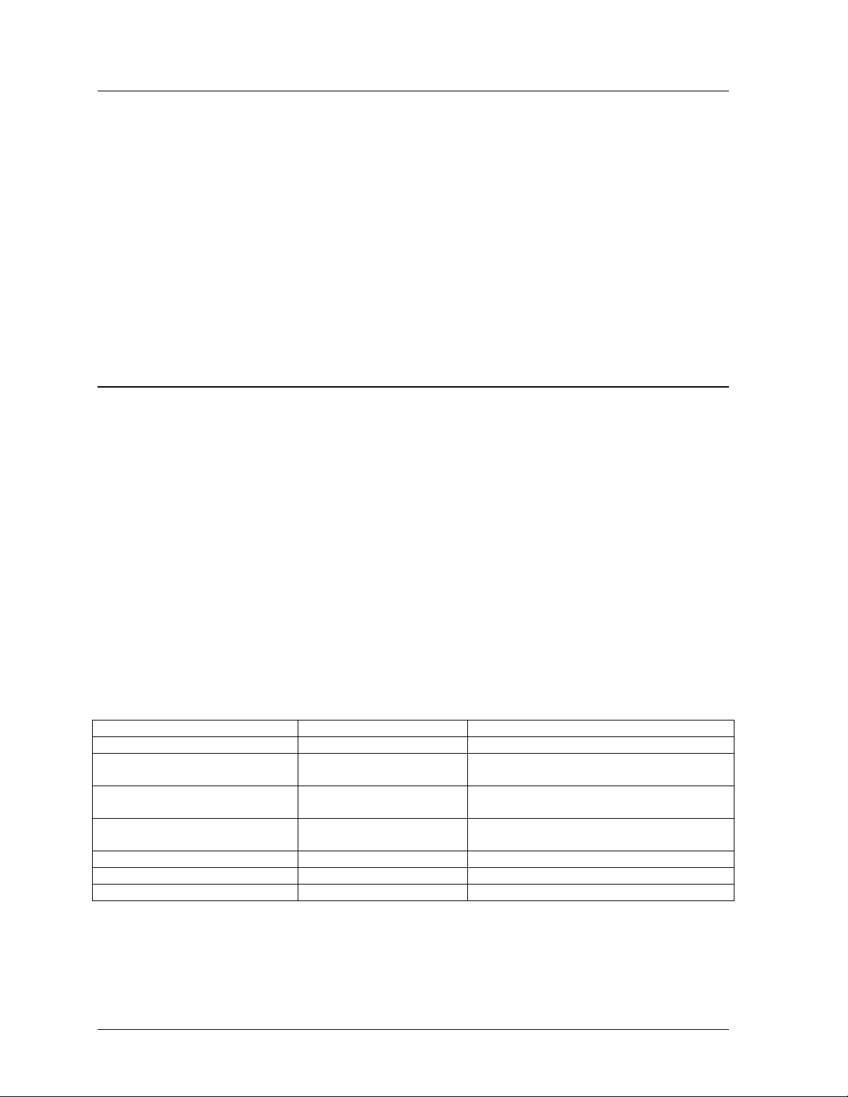
“DIP” switches are located on the controller’s MDC. The DIP switches set the hardware address,
which the software uses to identify that particular display. When replacing a controller board, be
sure to set the DIP switches in the same address configuration as the defective controller.
Note: Setting the DIP switches to address 0 (turn all the switches to OFF by flipping them toward
the printed switch numbers) can activate a test mode. The display’s power must be turned off and
then turned back on to run the test mode.
Maintenance &
Troubleshooting
4-3
Page 30
Switch 8 Switch 7 Switch 6 Switch 5 Switch 4 Switch 3 Switch 2 Switch
1
Off Off Off Off Off Off Off Off
Address
Test Mode
Off Off Off Off Off Off Off On
Off Off Off Off Off Off On Off
Off Off Off Off Off Off On On
Off Off Off Off Off On Off Off
Off Off Off Off Off On Off On
Off Off Off Off Off On On Off
Off Off Off Off Off On On On
… … … … … … … …
On On On On Off Off Off Off
…
240
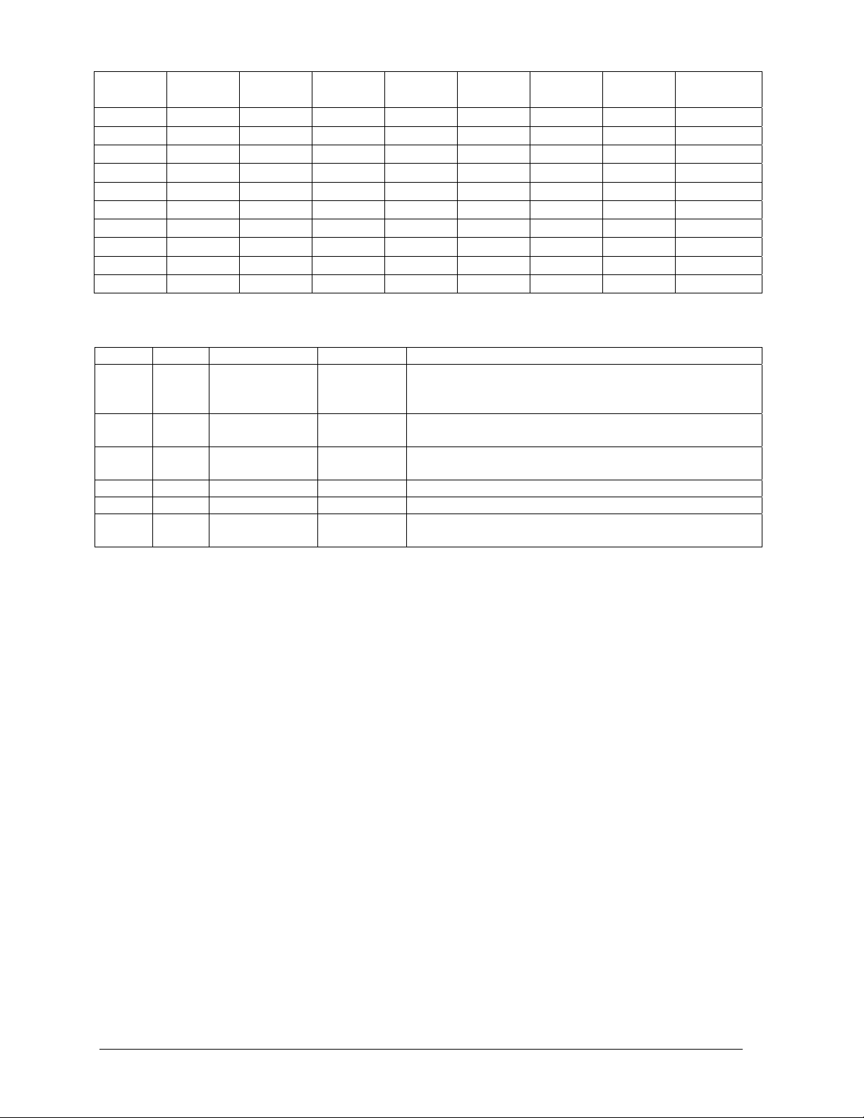
Four diagnostic LEDs are located on the controller; the table below tells what each LED denotes.
LED Color Function Operation Summary
TEMP Red Temperature
Level
LGHT Red Photocell Light
Level
RUN Red Controller Steady
PWR Green Power Always On Power to the data input circuit when lit.
RX1 Yellow Com 1 Flashes Turns on and flashes when receiving information.
RX2 Yellow Com 2 Flashes Turns on and flashes when receiving information,
Flashes Flash rate is dependent upon the temperature.
Flashes faster in high temperature and slows as the
temperature decreases.
Flashes Flash rate is dependent on the light level. Flashes
faster in bright light and slows as darkness descends.
A steady flash indicates the controller is running
Flash
correctly. Normal flash rate is about once a second.
typically used in custom applications.
The controller contains two jumpers (W1 and W2) for use with a modem system. The jumpers
must jump both pins for a modem system.
Complete the following steps to remove the controller from the display.
1. Disconnect power from J2.
2. Remove all power and signal connections from the board. “Locked” connectors are released
by squeezing together the tabs, then carefully pulling them from the jack. When replacing the
board, it is helpful to have the cables labeled as to which was removed from which connector.
3. Remove each of the six nuts holding the board in place.
4. Follow the previous steps in reverse order to install a new controller board.
Modules & Drivers
The module and driver board are a single functional unit. The LED power supplies are identified
as assemblies (refer to Power Supplies, following in this section). Each power supply unit
controls four modules; a power supply assembly (two power supply units) controls eight.
To remove a module, complete the following steps:
1. Locate the latch access fasteners on the module. One is centered below the top row of pixels
and one is centered above the bottom row.
2. With a c²Allen wrench, turn the latch access fasteners a quarter turn as seen in Figure 22.
The top one should be turned clockwise and the bottom one counter-clockwise.
3. Pull the display module far enough to reach around the back and disconnect the ribbon cables.
1
2
3
4
5
6
7
4-4
Maintenance &
Troubleshooting
Page 31

When installing a module, reverse the
previous steps and take note of the following
points:
· The weather-stripping on the back edge
of the module must be intact and in good
condition if it is to prevent water from
seeping into the display.
· The module latches must be fully
engaged to create a watertight seal around
the edge of the module. The module
should be firmly seated against the
display when the latches are fully
engaged.
Each module assembly is made up of a
module housing (containing LEDs and the
driver) and a louver assembly. Drawings B-
126111 and B-126112 illustrate the various
module components.
From time to time, it may become necessary
to remove one or more parts from the module
housing for repair or replacement. The
following sub-sections explain how to
disassemble a module.
Figure 22: Removing a Module
Removing the Louver Assembly
Complete the following steps to remove the louver assembly from the face of the module.
1. From the backside of the module, remove the five twist-on fasteners holding the louver
assembly to the module.
2. Lift the louver assembly straight away from the module.
Damaged louvers may reduce the brightness and contrast of this display. If any of the louvers
on the display are broken or damaged, the entire louver assembly must be replaced. Refer to
the Replacement Parts List in Section 4.11. When replacing the louver assembly take care not
to strip the plastic twist-on fasteners.
Power Supplies
The LED power supplies are identified as assemblies 0A-1241-4001 in the component location
drawings.
Complete the following steps to remove a power supply from the display:
1. Remove the module directly in front of the failed power supply.
2. Disconnect all the wires connected to the power supply.
3. Remove the hardware holding the power supply in place to free the unit.
4. Follow these steps in reverse order to install a new power supply. Refer to the display’s
Schematic when reconnecting the wires.
Maintenance &
Troubleshooting
4-5
Page 32

Light Detector
The light detector is internally mounted and wired at Daktronics. It is located in the bottom left
corner on the front of the display (identified as assembly 0A-1241-4001 (LT) in the Component
Layout Diagram). A 4-conductor cable connects the light detector to the controller board. The
cable is terminated at the terminal block on the light sensor and at TB7 on the controller board
(refer to your display’s schematic).
Light Detector
Pin No.
1 Green 3
2 White 4
3 Red 1
4 Black 2
N.C. Shield 2
Cable Wires
Color
Controller Board
TB7 Pin No.
Modem
If a modem was included with the display, it is located inside
the display next to the controller board.
1. To replace a modem, first disconnect the power and
signal connections (refer to Figure 23 for the location of
the power jack).
2. The modem is held in place with four screws. Remove
the screws and lift the modem out of the display.
3. Attach the new modem using the same four screws
removed in step 2, above.
The modem module has two LEDs. The Power LED should
remain lit while power is applied to the modem. The Active
LED will light when the modem is in the process of
communicating.
Figure 23: Modem
A modem system requires jumpers to be set
on the controller board. Refer to the
Controller section for the jumper settings.
Fiber Board
The fiber module has three LEDs. The power
LED (DS1) should remain lit while power is
applied to the module. The receive LED
(DS2) will light when the display fiber board
is accepting signal from the computer fiber
board. The transmit LED (DS3) will light
when the display fiber board is sending to the
computer fiber board. In addition, the fiber
module has two input fiber connectors, which
the computer or the previous display
connects to, and two output fiber connectors
that connect to the next display. The fiber
board connects to the controller board with a
small DB9 adapter and straight through RJ11
cable.
Figure 24: Fiber Optic Board
4-6
Maintenance &
Troubleshooting
Page 33

To replace a fiber optic board:
1. Disconnect the power and signal connections (refer to Figure 24 for disconnection of power).
2. The fiber optic board is held in place with four screws. Carefully remove them.
3. Install the new fiber board, replace the screws and reconnect power and signal cables.
4.5 Ventilation Systems (With Fans and Filters)
Ventilation fans should be checked after 1,500 hours of operation and every 1,500 hours after that to
ensure the display is being cooled properly. Fans should be checked more often if the display is
located in a dusty or harsh weather environment (i.e. along a gravel road with dust laden air).
· 1,500 hours is equivalent to 83 days if the display is operated for 18 hours a day and the
power to the display is turned off when not in use.
· 1,500 hours is equivalent to 62 days if the display is running non-stop for 24 hours a day.
Each time a module is removed, for whatever reason, take a minute to inspect the fans.
· Check the fan blades for dirt and debris. If the fan blades have a large accumulation of dirt
and debris, this indicates that the filters must be changed more often. Fan blades must be kept
clean to maintain fan efficiency and ensure proper cooling.
· Spin the fan blades with a pen or pencil to ensure that the bearings are free and the fan is still
in balance.
To check the operation of the fans, push the bypass button (momentary contact) on the thermostat
enclosure to temporarily turn the fans on:
· Hold your hand or a piece of light paper beneath the display to detect air movement.
· If the fan does not turn or does not operate smoothly, replace it. It is located behind A102, top
row, second module from the left.
Filters must be checked once a year or after every 1,500 hours of operation, whichever comes first.
Filters can be cleaned with water and a mild detergent, such as dish soap. Compressed air can also be
used to clean the filters provided the nozzle is held at least six inches away from the filter, the pressure
is no greater than 60 psi and the air is blown through the filter in the opposite direction from which air
normally flows. The arrow stamped on the frame filter indicates air flow direction.
4.6 Thermostats
Reference Drawings:
Component Layout Diagram...........................................................................Appendix B
A thermostat controls when the ventilation fans are turned on in the display. Refer to the Component
Layout Diagram for the location of the thermostat. The ventilation fans turn on when the inside of the
display reaches 85° F (29° C), and turn off at 70° F (21° C).
4.7 Weather Stripping
To ensure that the display is waterproof, weather stripping has been provided around the entire display
and around each module. It is important that the weather stripping is installed properly at all times or
water may leak into the display and damage the components.
Maintenance &
Troubleshooting
4-7
Page 34

4.8 Display Maintenance
A yearly inspection should be completed to maintain safe and dependable display operation. This
inspection should address the following issues.
· Loose Hardware
Verify fasteners, such as bolts and rivets, have not come loose. Fasteners should be checked
and tightened or replaced as required.
· Excessive Dust Buildup
Occasionally it may be necessary to vacuum the inside of the display cabinet to remove
dust/dirt buildup that may interfere with airflow.
· Water Intrusion – Water Stain Marks
Water can enter the display where weather stripping has come loose or deteriorated or where
fasteners have come loose allowing gaps in the panels or where moisture may be entering
around hardware. Check electronic components for displays of corrosion.
· Corrosion
Check the paint, and look for possible corrosion especially at footing s, structural tie points and
ground rods.
If any of the above conditions are noticed, action must be taken to correct the situation.
4.9 Troubleshooting
This sub-section contains some symptoms that may be encountered in the displays. This list does not
include every possible symptom, but does represent common situations that may occur.
Symptom/Condition Possible Cause/Remedy
One or more LEDs on a single module fail
to light.
One or more LEDs on a single module fail
to turn off.
A section of the display is not working. The
section extends all the way to the right side
of the display.
One row of modules does not work or is
garbled.
A group of modules, which share the same
power supply assembly, fail to work.
Entire display fails to work. · Check for proper line voltage into the power
Temperature always reads 32 degrees F/0
degrees C
· Replace/check ribbon cables on the module.
· Replace the module.
· Replace/check ribbon cables on module.
· Replace the module.
· Replace the first module/driver on the left side of the
first module that is not working.
· Replace the second module that is not working.
· Replace the power supply assembly on the first
module that is not working.
· Replace the ribbon cable.
· Replace first module.
· Replace controller.
· Check the fuses in the power termination box.
· Replace the power supply assembly.
termination panel.
· Check/replace the ribbon cable from the controller
to the modules.
· Check the voltage settings on the power supplies.
· Check/replace the signal cable to the controller.
· Replace the controller.
· Verify proper use of the software in the operation
manual.
· Check temperature sensor connections.
· Replace the temperature sensor.
· Replace the controller.
4-8
Maintenance &
Troubleshooting
Page 35

Display is stuck on bright or dim. · Check Manual/Auto dimming in Venus 1500
software.
· Check light detector cable.
· Check light detector for obstructions.
· Replace the light detector.
· Replace the controller.
4.10 Boot Up Initialization Information
Every time the display is powered up, the display will run through an initialization in which it will
display the following:
1. Output Test (DDDs)
2. Product Name (Galaxy)
3. Display Size (Row x Column)
4. Firmware Number (ED-12699)
5. Firmware Revision (Rev X.XX)
6. COM1 Configuration (C1: V15/RTD)
7. COM2 Configuration (C2: None)
8. Line Frequency (60 Hz)
9. Hardware Address (HW: XX)
10. Software Address (SW: XX)
11. Display Name
12. Modem (If modem is present)
4.11 Replacement Parts List
The following tables contain some of the items that may need to be replaced in these displays over a
period of time. Many of the parts within the display also list their part numbers on labels affixed to
them.
To prevent theft Daktronics recommends purchasing a lockable cabinet to store manuals and
replacement/spare parts.
Part Description Part Number
Controller II, 48x168, Louvered Galaxy 0A-1146-0067
Module, 2R2G2B (1:1) 8x8 (30x70) Type 1 0A-1208-2551
Power Supply Assembly, 2 A-1633, 1 A-1591 0A-1241-4001 &
0A-1213-4034
Thermostat Enclosure 85-70-9L 0A-1213-4024
Light Level Detector; 34mm 0A-1215-4001
Filter; Air, Gasket, 7.50” x 13.50” x .88” EN-1774
Fan; 250CFM, 115VAC, 0.65A, 5.84x6.0” B-1019
Transformer; Pri 115V, Sec 10VCT@1.2A (120V Displays) T-1072
Transformer; 115/240V Pri 10VCT@1.2A (240V Displays) T-1106
Filter, RFI Line 10 AMP 120 VAC Z-1007
Fan Finger Guard (for B-1019 fan) HS-1130
Fuse Holder; 1 Pos. Pnl Mt. ¼” X-1032
Thermostat; SPST NO Close 85 Open 70 S-1144
Modem Board; 232 Coated 0P-1146-0003
Fiber Board; RS232 to Fiber, 12V 0P-1127-0024
Jack; 6-Pin Female for Modem J-1094
Cable; 18” RJ11; 6-Cond. 0A-1137-0160
Signal Converter (RS232/RS422) 0A-1127-0237
Maintenance &
Troubleshooting
4-9
Page 36

Signal Converter (RS232/Fiber) 0A-1127-0239
Manual; Venus 1500 Operator’s, Version 2.0 ED-12717
Manual; Galaxy Outdoor 34mm Louvered Displays ED-12835
Ribbon Cable; 40 Cond. 30 AWG 18”
(Controller to Module, Module to Module)
Ribbon Cable Assy; 40 Pos, 66” W-1439
Ribbon Cable Assy; 40 Pos, 36” W-1423
Cable; 22 AWG (Light Sensor/Temp Sensor to Controller) W-1234
Flipped PC Connector; DB9F/RJ11F 0A-1146-0029
Digital Temp Sensor 0P-1151-0003
Electrical Contact Cleaner Lubricant / Cal-Lube CH-1019
W-1412
4.12 Daktronics Exchange/Repair & Return Programs
To serve customers’ repair and maintenance needs, Daktronics offers both an exchange and a repair
and return program. The exchange program reduces down time by providing timely replacement of
key components. This service is provided to qualified customers who follow the program guidelines
explained below. It is our pleasure to provide this service to ensure you get the most from your
Daktronics products. Please call our Help Desk (1-877 / 605-1113) if you have any questions
regarding the exchange program or any other Daktronics service.
When you call the Daktronics Help Desk, a trained service technician will work with you to solve the
equipment problem. You will work together to diagnose the problem and determine which exchange
replacement part to ship. If, after you make the exchange, the equipment still causes problems, please
contact our Help Desk immediately.
If the replacement part fixes the problem, package the defective part in the same packaging the
replacement part arrived in, fill out and attach the enclosed UPS shipping document and RETURN
THE PART TO DAKTRONICS. (You may use the same box and packing the exchange part was
sent in.) This will speed up the transaction and alleviate confusion when the failed component arrives
at Daktronics. (Daktronics expects immediate return of the exchange part if it does not solve the
problem.) For most equipment, you will be invoiced for the replacement part at the time it is shipped.
This invoice is due when you receive it.
Daktronics reserves the right to refuse equipment that has been damaged due to acts of nature or
causes other than normal wear and tear.
If the defective equipment is not shipped to Daktronics within 30 working days from the invoice date,
it is assumed you are purchasing the replacement part and you will be invoiced for it. This second
invoice represents the difference between the exchange price and the purchase price of the equipment.
This amount is due when you receive the second invoice. If you return the exchange equipment after
30 working days from invoice date, you will be credited for the amount on the second invoice minus a
restocking fee.
@To avoid a restocking charge, please return the defective equipment within 30 days from the
invoice date.
Daktronics also offers a Repair and Return program for items not subject to exchange.
Where to Send: To return parts for service, contact your local representative prior to shipment to
acquire a Return Material Authorization Number (RMA#). If y ou hav e no local representative, call the
Daktronics Help Desk for the RMA#. This will expedite the receiving process.
Packaging for Return: Package and pad the item well so that it will not be damaged in shipment.
4-10
Maintenance &
Troubleshooting
Page 37

Electronic components such as printed circuit boards should either be installed in an enclosure or
should be put in an anti-static bag before boxing. Please enclose your name, address, phone number
and a clear description of symptoms.
Mail: Daktronics, Inc., Customer Service
PO Box 5128
331 32nd Avenue
Brookings, SD 57006
Phone: Daktronics Help Desk: 1-877/605-1113
or 1-605/697-4034
Customer Service Fax: 1-605-697-4444
e-mail: helpdesk@daktronics.com
Maintenance &
Troubleshooting
4-11
Page 38

Page 39

Appendix A: Signal Converter
The following table gives the typical state of the signal converter when the LEDs are either on or off.
Refer to Figure 25 for an illustration of the signal converters and the locations of the various
components.
LED Indicators Typical States
ON Signal Converter (SC) is receiving power.
PWR
TX
RX
OFF
ON Steady
OFF Steady Normal state, SC is not transmitting data.
Brief Flicker SC is transmitting data.
ON Steady
OFF Steady Normal state, SC is not receiving data.
Brief Flicker SC is receiving data.
SC is not receiving power.
Internal 1 AMP Fuse is bad.
SC is not connected to a serial port.
(If connected to serial port) Serial port or serial
cable may be bad.
Field cabling between SC and display is bad,
connected to display out or terminated
incorrectly.
Figure 25: Signal Converters
0A-1127-0237 – Wire
The following tables list the jack pin-outs for a wire signal converter.
J2 & J3 - RJ/11 J4 & J5 – Phoenix
PIN OPERATION PIN OPERATION
1 GND 1 GND
2 TX-N (out) 2 RX-P (in)
3 TX-P (out) 3 RX-N (in)
4 RX-N (in) 4 TX-P (out)
5 RX-P (in) 5 TX-N (out)
6 GND 6 GND
PIN OPERATION
Appendix A: Signal Converter
J1 25 Pin DB-F
2 TX-P (out)
3 RX-P (in)
7 GND
A-1
Page 40

Loop-Back Test: To perform a loop-back, for testing purposes only, connect the following using
copper conductor jumpers.
L Note: This test should be performed with only one jack at a time. Do not connect loop back to
more than one jack at a time.
J2 & J3
TX-N to RX-N
TX-P to RX-P RX-N to TX-N
OR
0A-1127-0239 – Fiber
The following tables give the jack pin-outs for a fiber signal converter.
JACK OPERATION J1 – 25 Pin DB-F
J2 TX1 (out)
J3 RX1 (in) 2 TX-P (out)
J4 TX2 (out) 3 RX-P (in)
J5 RX2 (in) 7 GND
Loop-Back Test: To perform a loop-back, for testing purposes only, connect the following using
a fiber optic cable jumper.
J2 & J3 or J4 & J5
TX to RX
Serial Cable (W-1249)
This table lists the pin connections when using a serial cable (W-1249).
DB9-F DB25-F
Pin 3 – TX Pin 2 – TX
Pin 2 – RX Pin 3 – RX
Pin 5 – GND Pin 7 - GND
Serial Adaptor (A-1603)
DB9-F DB25-M
Pin 3 – TX Pin 2 – TX
Pin 2 – RX Pin 3 – RX
Pin 5 – GND Pin 7 - GND
J4 & J5
RX-P to TX-P
PIN OPERATION
A-2
Appendix A: Signal Converter
Page 41

Appendix B: Reference Drawings
Refer to Section 1.1 for information on reading drawing numbers. The following drawings are listed
in numerical order by size (A, B, etc.)
Temp Sensor Mounting............................................................................... Drawing A-79767
System Riser Diagram, Modem...................................................................Drawing A-88426
System Riser Diagram, RS422....................................................................Drawing A-92681
System Riser Diagram, RS232....................................................................Drawing A-96058
System Riser Diagram, Fiber....................................................................Draw i ng A-110559
Schematic; Fiber/Modem Input..................................................................Drawing A-125900
Mtg Clip Angles; AX-XXXX-40/48XXX-34B............................................... Drawing A-128799
Clip Angle Mounting; AX-XXX-8/32XX-34B...............................................Drawing A-128801
Signal Input, Venus 1500..........................................................................Drawing A-129110
Power Specs, 8x144 Display, RGB........................................................... Drawing A-148571
F. Assy, AF-3065-32***-34........................................................................Drawing A-148630
Assy, Power Supply A-1633 @2, A-1591.................................................. Drawing A-148636
Entrance Box 8/16.....................................................................................Drawing A-149160
Comp. Layout Diagram; AF-3065-848-34-RGB.........................................Drawing A-149301
Comp. Layout Diagram; AF-3065-864-34-RGB.........................................Drawing A-149309
Comp. Layout Diagram; AF-3065-880-34-RGB.........................................Drawing A-149310
Comp. Layout Diagram; AF-3065-896-34-RGB.........................................Drawing A-149311
Comp. Layout Diagram; AF-3065-8112-34-RGB.......................................Drawing A-149312
Comp. Layout Diagram; AF-3065-8128-34-RGB.......................................Drawing A-149315
Comp. Layout Diagram; AF-3065-8144-34-RGB.......................................Drawing A-149317
Comp. Layout Diagram; AF-3065-1648-34-RGB.......................................Drawing A-149321
Comp. Layout Diagram; AF-3065-1664-34-RGB.......................................Drawing A-149330
Comp. Layout Diagram; AF-3065-1680-34-RGB.......................................Drawing A-149333
Comp. Layout Diagram; AF-3065-1696-34-RGB.......................................Drawing A-149334
Comp. Layout Diagram; AF-3065-16112-34-RGB.....................................Drawing A-149336
Comp. Layout Diagram; AF-3065-16128-34-RGB.....................................Drawing A-149342
Comp. Layout Diagram; AF-3065-16144-34-RGB.....................................Drawing A-149347
Comp. Layout Diagram; AF-3065-2448-34-RGB.......................................Drawing A-149349
Comp. Layout Diagram; AF-3065-2464-34-RGB.......................................Drawing A-149357
Comp. Layout Diagram; AF-3065-2480-34-RGB.......................................Drawing A-149359
Comp. Layout Diagram; AF-3065-2496-34-RGB.......................................Drawing A-149361
Comp. Layout Diagram; AF-3065-24112-34-RGB.....................................Drawing A-149364
Comp. Layout Diagram; AF-3065-24128-34-RGB.....................................Drawing A-149365
Comp. Layout Diagram; AF-3065-24144-34-RGB.....................................Drawing A-149368
Comp. Layout Diagram; AF-3065-3248-34-RGB.......................................Drawing A-149402
Comp. Layout Diagram; AF-3065-3264-34-RGB.......................................Drawing A-149407
Comp. Layout Diagram; AF-3065-3280-34-RGB.......................................Drawing A-149408
Comp. Layout Diagram; AF-3065-3296-34-RGB.......................................Drawing A-149420
Comp. Layout Diagram; AF-3065-32112-34-RGB.....................................Drawing A-149421
Comp. Layout Diagram; AF-3065-32128-34-RGB.....................................Drawing A-149422
Comp. Layout Diagram; AF-3065-32144-34-RGB.....................................Drawing A-149427
Comp. Layout Diagram; AF-3065-4048-34-RGB.......................................Drawing A-149429
Power Termination Box............................................................................. Drawing A-149554
Comp. Layout Diagram; AF-3065-4064-34-RGB.......................................Drawing A-149460
Comp. Layout Diagram; AF-3065-4080-34-RGB.......................................Drawing A-149466
Comp. Layout Diagram; AF-3065-4096-34-RGB.......................................Drawing A-149467
Comp. Layout Diagram; AF-3065-40112-34-RGB.....................................Drawing A-149468
Appendix B: Reference Drawings
B-1
Page 42

Comp. Layout Diagram; AF-3065-40128-34-RGB..................................... Drawing A-149471
Comp. Layout Diagram; AF-3065-40144-RGB.......................................... Drawing A-149472
Comp. Layout Diagram; AF-3065-4848-34-RGB....................................... Drawing A-149477
Comp. Layout Diagram; AF-3065-4864-34-RGB....................................... Drawing A-149477
Comp. Layout Diagram; AF-3065-4880-34-RGB....................................... Drawing A-149479
Comp. Layout Diagram; AF-3065-4896-34-RGB....................................... Drawing A-149480
Comp. Layout Diagram; AF-3065-48112-34-RGB..................................... Drawing A-149482
Comp. Layout Diagram; AF-3065-48128-34-RGB..................................... Drawing A-149483
Comp. Layout Diagram; AF-3065-48144-34-RGB..................................... Drawing A-149484
F. Assy, AF-3065-24**-RGB-34 ................................................................Drawi ng A-149929
F. Assy, AF-3065-8**-RGB-34 .................................................................. Drawing A-149939
F. Assy, AF-3065-16**-RGB-34 ................................................................Drawi ng A-149968
F. Assy, AF-3065-40**-RGB-34 ................................................................Drawi ng A-150660
F. Assy, AF-3065-48**-RGB-34 ................................................................Drawi ng A-150661
Power Connection, AF-306X..................................................................... Drawing A-154965
Assy, Power Box 2 Position ......................................................................Drawing A-155736
Detail, Controller and Power Term Box 24 -48 High................................... Drawing A-156086
Exploded Front View, Single Panel Module...............................................Drawi ng B- 126111
Exploded Rear View, Single Panel Module...............................................Drawi ng B- 126112
Shop Drawing, AF-3065-8-32 High...........................................................Drawi ng B- 148418
Shop Drawing; AF-3065-40-48 High.........................................................Drawing B-148419
Schematic, AF-3065-24x***-9, RGB.......................................................... Drawing B-149403
Schematic, AF-3065-8x***-9, RGB............................................................Draw i ng B-149469
Schematic, AF-3065-16/32/48x***-9, RGB................................................Drawing C-149070
Schematic, AF-3065-40x***-9, RGB.......................................................... Drawing C-149437
B-2
Appendix B: Reference Drawings
Page 43

Page 44

Page 45

Page 46

Page 47

Page 48

Page 49

Page 50

Page 51

Page 52

Page 53

Page 54

Page 55

Page 56

Page 57

Page 58

Page 59

Page 60

Page 61

Page 62

Page 63

Page 64

Page 65

Page 66

Page 67

Page 68

Page 69

Page 70

Page 71

Page 72

Page 73

Page 74

Page 75

Page 76

Page 77

Page 78

Page 79

Page 80

Page 81

Page 82

Page 83

Page 84

Page 85

Page 86

Page 87

Page 88

Page 89

Page 90

Page 91

Page 92

Page 93

Page 94

Page 95

Page 96

Page 97

Page 98

Page 99

Page 100

 Loading...