

Page 1
i
Galaxy Outdoor 7.62mm
Series AF-3020
Installation, Maintenance, &
Troubleshooting Manual
ED13518
ED13518
Product#1272
Rev 0 – 29 August 2002
Copyright ã 2002 Daktronics, Inc.
All rights reserved. While every precaution has been taken in the preparation
of this manual, the publisher assumes no responsibility for errors or
omissions. No part of this book covered by the copyrights hereon may be
reproduced or copied in any form or by any means – graphic, electronic, or
mechanical, including photocopying, taping, or information storage and
retrieval systems – without written permission of the publisher.
®
Venus
is a registered trademark of Daktronics, Inc.
331 32nd Ave PO Box 5128 Brookings SD 57006
Tel 605-697-4036 or 877-605-1115 Fax 605-697-4444
www.dak tronics.com e-mail: h elpdesk@daktronics.com
Page 2

Page 3

Table of Contents
Section 1 : Introduction............................................................................................... 1-1
1.1 How to Use this Manual.............................................................................................1-1
1.2 Safety Precautions......................................................................................................1-2
1.3 Daktronics Nomenclature...........................................................................................1-2
1.4 Network Concepts......................................................................................................1-3
RS/232 Network.........................................................................................................1-3
RS/422 Network.........................................................................................................1-4
Modem Network.........................................................................................................1-4
Fiber Optic Network...................................................................................................1-4
1.5 Display Overview.......................................................................................................1-4
1.6 Part Definitions ..........................................................................................................1-5
Section 2 : Mechanical Installation............................................................................. 2-1
2.1 Support Structure Design...........................................................................................2-1
2.2 Display Mounting.......................................................................................................2-1
Wall/Pole Mount........................................................................................................2-1
Section 3 : Electrical Installation................................................................................ 3-1
3.1 Common Connectors in Galaxy Displays..................................................................3-1
3.2 Conduit.......................................................................................................................3-2
3.3 Power..........................................................................................................................3-3
Grounding...................................................................................................................3-3
Power Installation.......................................................................................................3-3
3.4 Control Cable Requirements......................................................................................3-5
RS/232 ....................................................................................................................... 3-5
RS/422 ....................................................................................................................... 3-5
Modem .......................................................................................................................3-5
Fiber Optic .................................................................................................................3-5
3.5 Signal Termination from Computer to Display..........................................................3-6
RS/232 ....................................................................................................................... 3-6
RS/422 ....................................................................................................................... 3-6
Modem .......................................................................................................................3-6
Fiber Optic .................................................................................................................3-7
3.6 Signal Termination Between Two (or More) Displays..............................................3-7
RS/422 Interconnection..............................................................................................3-7
Fiber Interconnection.................................................................................................3-7
3.7 First Time Turn On ....................................................................................................3-8
Section 4 : Maintenance & Troubleshooting.............................................................. 4-1
4.1 Weather Stripping ......................................................................................................4-1
4.2 Display Access/LED Module Removal .....................................................................4-1
4.3 Power Supply .............................................................................................................4-1
4.4 Controller Board.........................................................................................................4-2
Table of Contents
i
Page 4

Display Controller ..................................................................................................... 4-2
LEDs & Jumpers........................................................................................................ 4-2
Controller Address & Test Mode .............................................................................. 4-3
4.5 Light Detector............................................................................................................ 4-3
4.6 Transformer ............................................................................................................... 4-4
4.7 Communicate Accessories......................................................................................... 4-4
Accessing and Replacing the Modem........................................................................ 4-4
Fiber Board................................................................................................................ 4-4
LEDs & Jumpers........................................................................................................ 4-4
Surge Suppressor, RS422 .......................................................................................... 4-5
4.8 Structural Inspection.................................................................................................. 4-5
4.9 Troubleshooting......................................................................................................... 4-6
4.10 Boot Up Initialization Information............................................................................ 4-6
4.11 Replacement Parts ..................................................................................................... 4-7
4.12 Daktronics Exchange/Repair & Return Programs..................................................... 4-7
Appendix A: Optional Temperature Sensor................................................................ A-1
Appendix B: Signal Converter.....................................................................................B-1
Appendix C: Reference Drawings ...............................................................................C-1
ii
Table of Contents
Page 5

List of Figures
Figure 1: Drawing Label.....................................................................................................................1-1
Figure 2:Module Numbering Example – 48x240 Front......................................................................1-2
Figure 3: Module Numbering..............................................................................................................1-2
Figure 4: Typical Label.......................................................................................................................1-3
Figure 5: Ribbon Cable Connector #2 ................................................................................................3-1
Figure 6: Fiber Optic Connector.........................................................................................................3-1
Figure 7: RJ11 Connector ...................................................................................................................3-1
Figure 8: Termination Panel (Left) and Termination Block (Right) ..................................................3-2
Figure 9: Phoenix Connector ..............................................................................................................3-2
Figure 10: Mat-n-Lok Connector........................................................................................................3-2
Figure 11: Tab Connector ...................................................................................................................3-2
Figure 12: Installation with Ground and Neutral Conductor Provided...............................................3-4
Figure 13: Installation with only Neutral Conductor Provided...........................................................3-4
Figure 14: Display Controller .............................................................................................................4-2
Figure 15: Location of DIP Switches..................................................................................................4-3
Figure 16: Modem...............................................................................................................................4-4
Figure 17: Fiber Optic Board..............................................................................................................4-4
Figure 18: Surge Protector, RS422 .....................................................................................................4-5
Figure 19: Temperature Sensor Eave/Wall Mounting....................................................................... A-1
Figure 20: Temperature Sensor Mounting to Bottom of Display......................................................A-1
Figure 21: Signal Converters ............................................................................................................. B-1
List of Figures
iii
Page 6

Page 7
Section 1 : Introduction
1.1 How to Use this Manual
This manual explains the installation, maintenance and troubleshooting of a Daktronics Galaxy
outdoor LED (light emitting diode) displays controlled by a Venus
®
1500 controller. For questions
regarding the safety, installation, operation or service of this system, please refer to the telephone
numbers listed on the cover page of this manual.
The manual is divided into seven sections: Introduction, Mechanical Installation, Electrical
Installation, Maintenance & Troubleshooting and Appendices A, B and C.
· Introduction covers the basic information needed to make the most of the rest of this manual.
Take time to read the entire introduction as it defines terms and explains concepts used
throughout the manual.
· Mechanical Installation provides general guidance on sign mounting.
· Electrical Installation provides general guidance on terminating power and signal cable at the
sign.
· Maintenance & Troubleshooting addresses such things as removing basic sign components,
troubleshooting the sign, performing general maintenance and exchanging sign components.
· Appendix A provides information for the optional temperature sensor.
· Appendix B covers information pertaining to the signal converters.
· Appendix C includes the drawings referenced in this manual.
Daktronics identifies manuals by an ED number located on the cover page of each manual. For
example, this manual would be referred to as ED13518.
Listed below are a number of drawing types commonly used by Daktronics, along with the
information that each is likely to provide. This manual might not contain all these drawings.
· System Riser Diagrams: overall system layout from control computer to sign, power and phase
requirements.
· Shop Drawings: fan locations, mounting information, power and signal entrance points and
access method (front and rear).
· Schematics: power and signal wiring for various components.
· Component Placement Diagrams: locations of critical internal sign components such as power
supply assemblies, controller boards, thermostats and light detectors.
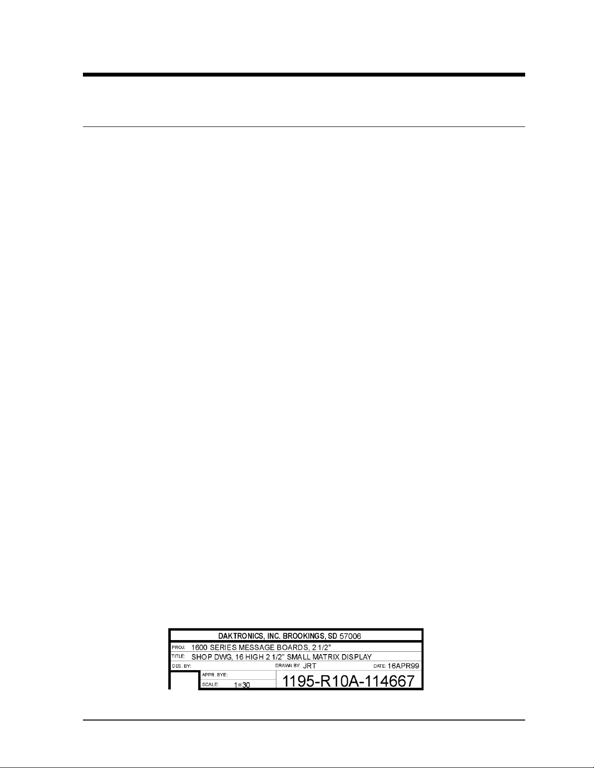
Figure 1 illustrates Daktronics drawing label. The drawing number is located in the lower-right
corner of the drawing. Listing the last set of digits and the letter preceding them identifies drawings in
the manual. In the example below, the drawing would be referred to as Drawing A-114667.
Reference drawings are inserted in Appendix C at the end of the manual.
Figure 1: Drawing Label
Introduction 1-1
Page 8
All references to drawing numbers, appendices, figures or other manuals are presented in bold
typeface, as shown below.
“Refer to Drawing A-114667 in Appendix C for the power supply location.”
Additionally, drawings referenced in a particular section are listed at the beginning of that section as
seen in the following example:
Reference Drawings:
Component Placement Diagram......................................................... Drawing A-114667
Daktronics signs are built for long life and require little maintenance. However, from time to time,
certain sign components will need replacing. The Replacement Parts List in Section 4.11 provides the
names and part number of components that may need to be ordered during the life of the sign.
Following the Replacement Parts List is the Exchange/Replacement Procedure in Section 4.12.
Refer to these instructions if any sign component needs replacement or repair.
1.2 Safety Precautions
1. Read and understand these instructions before installing.
2. Be sure that the display is properly grounded.
3. Disconnect power before working on the display.
4. Do not modify the display structure or attach any panels or coverings to the display
without the written consent of Daktronics, Inc.
5. Care must be taken when handling the display’s face panel to prevent any injuries or
damage, especially in windy conditions.
1.3 Daktronics Nomenclature
To fully understand some Daktronics drawings, such as
schematics, it is necessary to know how various
components are labeled in those drawings. This
information is also useful when trying to communicate
maintenance or troubleshooting efforts.
A module is the building block of the Galaxy sign. Each
module measures 16 pixels high by 48 pixels wide. By
placing modules side-by-side and on top of one another a sign
of any size can be designed and built. Individual modules can
be easily removed from the sign if required. Figure 2
illustrates how Daktronics numbers modules on a Galaxy
sign. Figure 3 breaks down the module numbering method.
Figure 2:Module Numbering Example – 48x240
Front
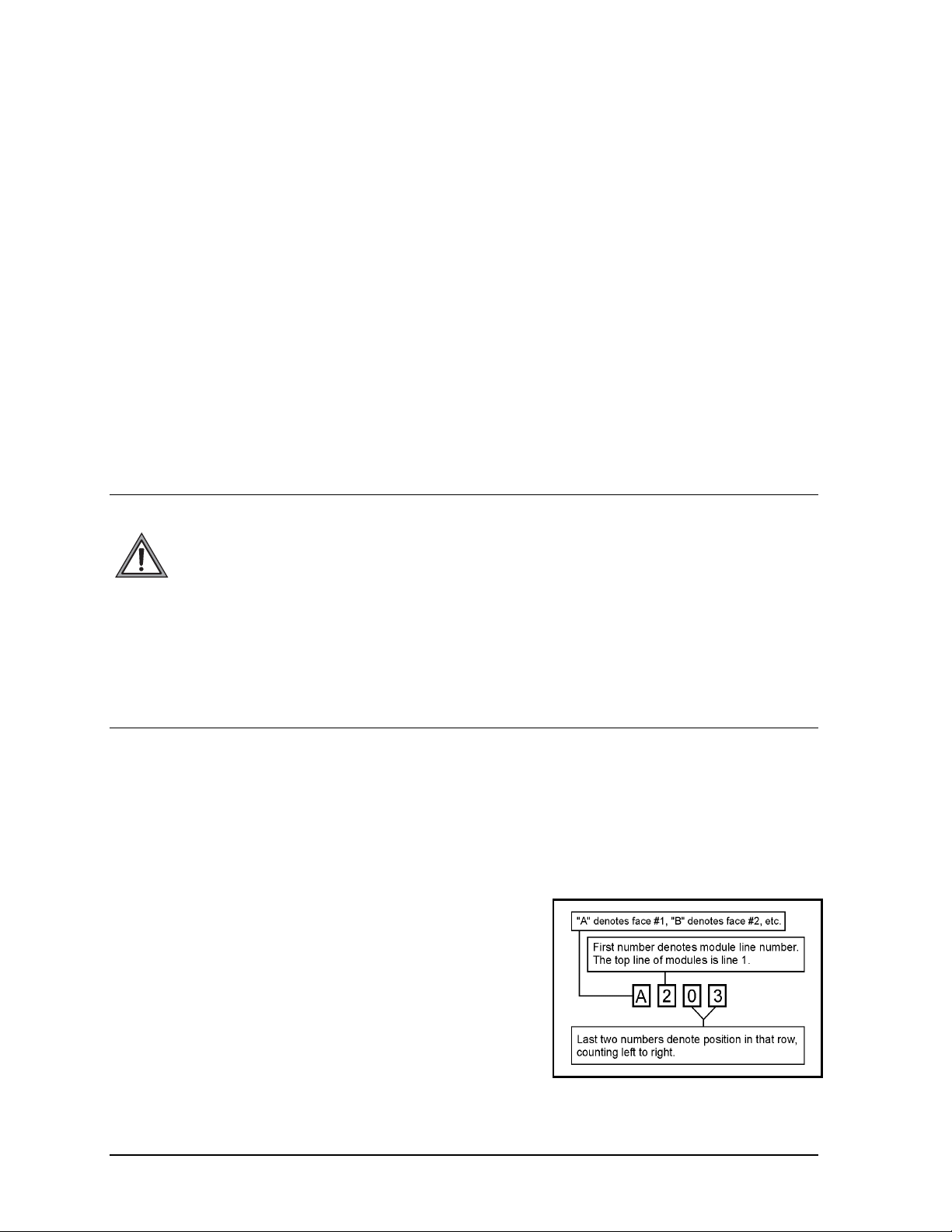
Figure 3: Module Numbering
1-2
Introduction
Page 9
The label “A” on a drawing typically denotes an assembly. An assembly can be a single circuit board
or a collection of components that function together, usually mounted on a single plate or in a single
enclosure. Assemblies are divided into two types: those that route signal and those that route power.
In addition, the following labeling formats might be found on various Daktronics drawings:
· “TB??” denotes a termination block for power or signal cable.
· “F??” denotes a fuse.
· “E??” denotes a grounding point.
· “J??” denotes a power or signal jack.
· “P??” denotes a power or signal plug for the opposite jack.
Finally, Daktronics part numbers are commonly found on drawings. Those part numbers can be used
when requesting replacement parts from Daktronics Customer Service. Take note of the following
part number formats:
· “0P-????-????” denotes an individual circuit board, such as a driver board.
· “0A-????-????” denotes an assembly, such as a circuit board and the plate or bracket to which it is
mounted. A collection of circuit boards working as a single unit may also carry an assembly label.
· “W-????” denotes a wire or cable. Cables may also carry the assembly numbering format in
certain circumstances. This is especially true of ribbon cables.
· “F-????” denotes a fuse.
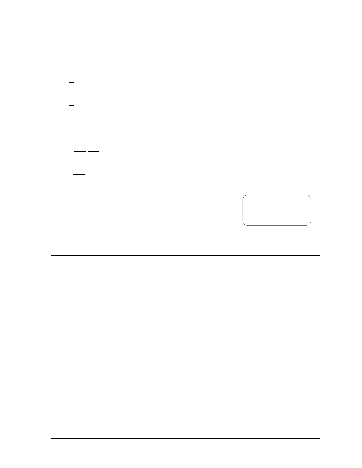
Most circuit boards and components within this sign carry a label that
lists the part number of the unit. If a circuit board or assembly is not
listed in the replacement parts list in Section 4, use the label to order
a replacement. A typical label is shown in Figure 4. The part number
is in bold.
0P-1195-0001
SN: 6343
05/19/99 REV.1
Figure 4: Typical Label
1.4 Network Concepts
The concept of using LED displays as a cost effective, high impact method of communication is
rapidly growing throughout many industries and businesses. The reasons for this growth are many,
but the need for additional features and complexity of multiple sign installations has emerged, and
Daktronics display systems have been designed to meet those needs. The common thread to most
client requests is a means of programming and controlling a group of signs from a central control
point. Daktronics responded by developing a powerful system of interconnecting and controlling
signs. One network of signs can consist of a maximum of 240 signs. Great care has been taken to
design products that will satisfy a wide variety of installations. Some of the design goals of these
systems include the following:
· Easy transfer of messages
· The ability to tell a sign or group of signs in a network which message should be run
· The ability to determine the status of any sign on the network
· The ability to control multiple sign technologies on the same network
There are four network systems available: RS/232, RS/422, modem and fiber optic.
RS/232 Network
RS/232 (EIA/TIA-232-E) is a standard communication interface that employs a single-ended
serial transmission scheme that uses a maximum cable length of 8 meters (25 feet). This interface
was designed for computer communication at short distances. All computers have an RS/232
communications port. Refer to Section 3 for additional information.
Introduction 1-3
Page 10
RS/422 Network
RS/422 (EIA/TIA-422-B) is a standard communication interface that utilizes a differential
balanced transmission scheme that uses a typical maximum cable length of 1.2 km (approximately
4000 feet). The main advantage to RS/422 over RS/232 is the longer cable length that is possible.
A signal converter is needed to convert the computer’s RS/232 to RS/422. Refer to Section 3 for
additional information.
Modem Network
The modem is a standard communication interface that utilizes standard phone transmission lines.
The phone company assigns each phone line a number that the modem uses to communicate
between the controller and the display. The display must have a dedicated phone line. Refer to
Section 3 for additional information.
Fiber Optic Network
A fiber optic network is a standard communication method transmitting light (signal) through a
glass fiber. Fiber optic cable has a maximum length of 2,000 feet. A signal converter is required
to convert the computer’s RS/232 interface to a light signal.
1.5 Display Overview
Refer to project specific shop drawings for details of the display.
The Daktronics outdoor LED displays have been designed and manufactured for performance,
reliability, easy maintenance and long life. The displays consist of an array of LED pixels. The
configuration of LED pixels is dependent on the family of LED displays.
A typical system consists of a Windows
and one or more displays. The displays are offered as single-face displays, which are single-sided
stand-alone units. The AF-3020 can be a double-sided display with two singles back to back each
using a separate controller.
The Venus 1500 is a software package that runs under Windows
â
operating systems on an IBM
-compatible computer. Refer to the Venus 1500 controller manual for
installation and maintenance of the Venus 1500 editing station.
The Galaxy Series AF-3020 displays are matrix-based outdoor LED displays that are available in
monochrome red or amber characters. They are offered as 16, 32, or 48 pixel high displays with a
standard 7 high 7.62mm minimum character in different lengths. The Galaxy model numbers are
described as follows: AF-3020-RRxCCC-7.62-SF-Z
AF-3020
RR
CCC
= Outdoor Galaxy Display
= 16, 32 or 48 Rows High
= Num ber of Columns Long (96, 144, 192 and 240 are
available)
7.62
SF
Z
= 7.62mm Character Height
= Single Face (SF)
= Monochrome Red (R) or Monochrome Amber ( A)
â
based personal computer (PC) running Venus 1500 software
â
95, Windowsâ 98 or Windows NTâ
1-4
Introduction
Page 11

1.6 Part Definitions
The following illustrations depict some of the more commonly accessed Galaxy sign components.
Because Daktronics occasionally alters standard design to meet customer needs, the actual sign design
may very slightly from the illustrations below.
This is only a brief overview. Refer to Section 4 for more detailed information on maintaining and
troubleshooting various sign components.
Column: Vertical group of pixels.
Com Port – Serial Port: Connector on the back of the controller PC. The Com Port is used to control
the sign network through either a DB9 or DB25-pin serial connector.
Controller Board: Controls the data for the entire display. It is located behind the bottom left
module.
Display Board: 16 row by 48-column array of pixels.
Display Configuration: Refers to a display’s model number, address, etc. This information will be
automatically displayed when the display is powered up.
Driver: Located on the back of the display board.
Driver Board: The LED pixels are mounted directly onto the driver/pixel board. This board is also
responsible for the switching and intensity levels of the LEDs.
Face Panel: Latching, hinged door that hinges downward, which the modules are mounted to.
Fiber Optic: Standard communication method using light (signal) transmitted through a glass fiber.
Fiber optic cable has a maximum length of 2,000 feet. A signal converter is required.
LED (Light Emitting Diode): Electrical component which creates a single point of light on the
display. There are 768 LEDs per module.
Modem: Uses standard telephone cable routed through conduit. Ask the telephone company which
colors are used by the TIP, and the RING for signal hook up. Note: The telephone lines must be
dedicated lines and not run through a switch board/communications system.
Module: Unit of the display that contains the LEDs, display board and driver board.
Network: Consists of multiple signs connected to each other. Up to 240 Venus 1500 controlled
displays can exist on one network.
Pixel: Single LED in the display.
RS/232: Standard PC communication type with a maximum cable length of 25 feet (8 meters).
RS/422: Standard differential communication type with a maximum cable length of 4000 feet (1.2
kilometers).
Row: Horizontal group of pixels.
Introduction 1-5
Page 12

RX LED: LED on the signal converter that indicates if the display is sending data back to the signal
converter.
Sign Address: Identification number assigned to each sign in a network. The control software uses
the address to locate and communicate with each display independently. Displays that are on the same
network cannot have the same address.
Signal Cable Tester: Used to test the cable connections and data communication.
Signal Converter: Daktronics supplied unit which converts the data from RS/232 to RS/422 (wire
converter) or RS/232 to light signals (fiber converter). The signal converter is used in RS/422 systems
or fiber systems respectively.
Surge Suppressor (Surge Protector): Device inserted in the alternating current utility line and/or
telephone line to prevent damage to electronic equipment from voltage "spikes" called transients.
TX LED: LED on the signal converter, which indicates the control PC, is sending data to the display.
Venus 1500: Daktronics designed, Windows based software used to create and edit messages on the
displays.
1-6
Introduction
Page 13

Section 2 : Mechanical Installation
Note: Daktronics engineering staff must approve any changes that may affect the weather tightness of
the display. If any modifications are made, detailed drawings of the changes must be submitted to
Daktronics for evaluation and approval, or the warranty may be void.
Daktronics is not responsible for the integrity of the mounting structure or any mounting hardware not
provided by Daktronics. It is the customer’s responsibility to ensure the structure and any additional
hardware have been approved by a qualified structural engineer.
2.1 Support Structure Design
Support structure design depends on the mounting methods, display size and weight. The structure
design is critical and should be done only by a qualified individual. It is the customer’s responsibility
to ensure that the structure and mounting hardware are adequate. Daktronics is not responsible for the
installations or the structural integrity of support structures done by others.
Note: Project specific Shop Drawings are provided for special circumstances where there is a special
mounting method used.
2.2 Display Mounting
It is the customer’s responsibility to ensure that the installation will meet local standards. The
mounting hardware must be capable of supporting all components to be mounted. The mounting
hardware and method are the responsibility of the customer. Refer to the project specific shop
drawings for the approximate weight and size of each model of display. Daktronics is not responsible
for the installations or the structural integrity of support structures done by others.
Daktronics recommends a wall/pole mounting method. Remember to have all mounted displays
inspected by a qualified structural engineer.
Note: The display has a hinged face panel. Care must be taken to allow the door to properly open
(refer to the project specific shop drawing).
Wall/Pole Mount
Note: It is the customer’s responsibility to determine the proper wall/pole mounting method and
location of the display. The number of attachment points needed and the structure must be
reviewed by a qualified structural engineer and meet all national and local codes. Daktronics is
not responsible for the installations or the structural integrity of support structures installed by
others.
Mounting channels/angles on the back of the display may be used as a wall/pole mount method.
There are ¼" bolts tightened into the rear of the display (Refer to the rear view of the shop
drawing) to assist with mounting. Once the proper mounting method and mounting
channels/angles are determined, attach the mounting channels/angles to the back of the display
using the ¼" bolts. Sealing washers or waterproof sealant must be placed between the display and
the mounting channel/angle to prevent water leaking into the display. (Refer to the rear view on
the shop drawing.)
Mechanical Installation
2-1
Page 14

There are five conduit knockouts for power or signal cables on the rear of the display as noted in
the display’s shop drawing. Any hole that is punched or drilled in the display must be
waterproofed (either using a waterproof plug or conduit) to prevent water from entering the sign.
2-2
Mechanical Installation
Page 15

Section 3 : Electrical Installation
Note: Only a qualified individual should terminate power and signal cable within this Daktronics
display.
Note: The Daktronics engineering staff must approve any changes made to the display. Before
altering the display, detailed drawings for the proposed modifications must be submitted to the
Daktronics engineering staff for evaluation and approval or the warranty will be rendered null and
void.
3.1 Common Connectors in Galaxy Displays
Many different types of connectors are used for power and signal connection in this display. Take
special care when disengaging any connector so as not to damage the connector, the cable or the
circuit board.
When pulling a connector plug from a jack, do not pull on the wire or cable; pull on the jack
itself. Pulling on the wires may damage the connector.
The following information presents some common connectors encountered during display installation
and maintenance.
1. Ribbon Cable Connectors:
Daktronics uses a variety of ribbon cables and ribbon cable connectors. The
most commonly used ribbon cable connector is seen in Figure 5. To
disconnect ribbon cable connector #2, pull each of the plastic locking arms
outward and remove the plug.
2. Fiber Optic Connectors:
At each end of a fiber optic cable is a “twiston” connector. To remove the fiber plug
from its jack, push it toward the jack and
Figure 6: Fiber Optic
Connector
3. Phone Jacks (RJ11 Connector):
RJ connectors, as seen in Figure 7: RJ11 Connector, are similar to the
telephone connectors found in homes. In order to remove this plug from
the jack, depress the small clip on the underside of the plug.
Before replacing an RJ connector, spray it with Deoxit
to remove any foreign matter that may cause signal problems. In
addition, apply a generous amount of Cailube
plug before inserting it into the jack. This paste will protect both the plug
and the jack from corrosion.
twist it counter-clockwise until the plug can
be pulled free. Figure 6 illustrates a common
type of fiber optic connector.
™
contact cleaner
™
protector paste to the
Figure 5: Ribbon
Cable Connector #2
Figure 7: RJ11
Connector
Electrical Installation
3-1
Page 16

4. Termination Panels & Termination Blocks:
Termination panels and termination blocks are most
often used to connect internal power and signal wires
to wires of the same type coming into the display
from an external source. Most signal wires will come
with forked connectors crimped to the ends of the
wire. Power wires need to have one-half inch of
insulation stripped from the end of the wire prior to
termination. Tighten all screws firmly to ensure a
good electrical connection. Refer to Figure 8.
Figure 8: Termination Panel (Left) and
Termination Block (Right)
5. Phoenix-Style Connectors:
Phoenix-style connectors, which are usually green, are often used for
signal termination on circuit boards. Refer to Figure 9. One-quarter inch
of insulation must be stripped from the wire prior to termination. To
remove a wire, turn the above screw counter-clockwise to loose the
connectors grip on the wire. To insert a wire, push the bare wire into the
connector and turn the above screw clockwise to lock the wire into place.
™
6. Mate-n-Lok
Connectors:
The Mate-n-Lok connectors found in this display are
white and come in a variety of sizes. Figure 10
illustrates a four-pin Mate-n-Lok connector. To remove the
plug from the jack, squeeze the plastics locking clasps of the
side of the plug and pull it from the jack.
7. Tab Connectors:
The tab connector, illustrated in Figure 11, is found in most
Daktronics displays. Grab the connector on the plastic
terminal cover when removing. Do not pull it off the tab by
Figure 10: Matn-Lok
Connector
pulling on the wire.
Figure 9: Phoenix
Connector
Figure 11: Tab
Connector
3.2 Conduit
Reference Drawings:
System Riser Diagram (Modem) ........................................................... Drawing A-88426
Power/Signal Termination Panel...........................................................Drawing A-88427
System Riser Diagram (422)................................................................. Drawing A-92681
System Riser Diagram, Fiber.............................................................. Drawing A-110559
Power Termination Box ....................................................................... Drawing A-140262
Daktronics does not include the conduit. Possible power and signal entrances are designated by
center punches. Refer to the project specific shop drawing for the placement of the center punches.
Separate conduit must be used to route the following:
· Power
· Signal IN wires
· Signal OUT wires (if signal is required for another display)
3-2
Electrical Installation
Page 17

To prepare for power and signal entrance:
1. Release the face panel latches using a tubular key (provided by Daktronics).
2. Open the face panel.
3. Clear the center punch area for drilling.
Punch or drill out the desired center punch. Be careful that none of the internal components are
damaged. Attach the conduit and route the power and signal cables. Refer to Drawing A-88427 and
A-140262 for an illustration of the power and signal termination panels.
3.3 Power
The body of this paragraph will give installation specific details for each manual receiving this
section. It will include system risers, shop drawings and assembly drawings. It will also include
voltage requirements if the manual is for a specific location.
Proper power installation is imperative for proper display operation. The following sub-sections give
details of display power installation. Qualified personnel must perform electrical installations.
Unqualified personnel should not attempt to install the electrical equipment. Serious danger to
equipment and personnel could occur if equipment is improperly installed.
G ounding r
Displays must be grounded according to the provisions outlined in Article 250 of the National
Electrical Code
®
. Daktronics recommends a resistance to ground of 10 ohms or less. The
electrical contractor who is performing the electrical installation can perform verification of
ground resistance. Scoreboard Sales and Service personnel can also perform this service
The display system must be connected to earth-ground. Proper grounding is necessary for reliable
equipment operation. It also protects the equipment from damaging electrical disturbances and
lightning. The display must be properly grounded or the warranty will be void.
The material of an earth-ground electrode differs from region to region and from conditions
present at the site. Consult the National Electrical Code and any local electrical codes that may
apply. The support structure of the display cannot be used as an earth-ground electrode. The
support is generally embedded in concrete, and if in earth, the steel is either primed or it corrodes,
making it a poor ground.
Power Ins allation
t
There are two considerations for power installation; installation with ground and neutral
conductors provided and installation with only a neutral conductor provided. These two power
installations differ slightly, as described in the following paragraphs:
Installation with Ground and Neutral Conductors Provided
For this type of installation, the power cable must contain an isolated earth-ground conductor.
Under this circumstance, do not connect neutral to ground at the disconnect or at the display.
This would violate electrical codes and void the warranty. Use a disconnect so that all hot
lines and neutral can be disconnected. Refer to Figure 12 for installation details. The
National Electrical Code requires the use of a lockable power disconnect within sight of or at
the display.
Electrical Installation
3-3
Page 18

Figure 12: Installation with Ground and Neutral Conductor Provided
Installation w ith Only a Neutral Conductor Provided
Installations where no grounding conductor is provided must comply with article 250-32 of
the National Electrical Code. If the installation in question meets all of the requirements of
article 250-32, the following guidelines must be observed:
· Connect the grounding electrode cable at the local disconnect, never at the display panel
board.
· A disconnect that opens all of the ungrounded phase conductors should be used.
· The neutral and the ground conductors should be bonded in the display panel board.
Refer to Figure 13 for installation details.
Figure 13: Installation with only Neutral Conductor provided
3-4
Electrical Installation
Page 19

3.4 Control Cable Requirements
RS/232
This cable is a 2-conductor shielded cable used to transmit an RS/232 signal (Daktronics part
number W-1117). This shielded cable should not be subjected to mechanical flexing after
installation. This cable is not for direct burial and should be routed in a dedicated, grounded
metallic conduit at the base of the display structure. This cable has a maximum length of 25 feet.
RS/422
This cable is a 6-conductor shielded cable used to transmit an RS/422 signal (Daktronics part
number W-1210). This shielded cable consists of unpaired wires. They should not be subjected to
mechanical flexing after installation. This cable is not for direct burial and should have one of the
following routings:
· In dedicated metallic conduit
· Inside buildings - if cable is not in conduit, keep away from interference signals.
With interference signals (such as power conductors, intercom, etc.) typically a two-foot
separation is required.
Modem
The modem option will use standard telephone cable routed through conduit. The local telephone
company will need to assist in this installation.
Ask the telephone company which colors are used by the TIP, and the RING for signal hook up.
Note: The telephone lines must be dedicated lines and not run through a switch
board/communications system.
Fiber Opt c i
This cable is a 4-fiber cable (Daktronics part number W-1376). Two fibers are used, leaving the
other two as spares. The cable may be either direct burial or routed in conduit but it should not be
subjected to mechanical flexing.
Electrical Installation
3-5
Page 20

3.5 Signal Termination from Computer to Display
Reference Drawings:
System Riser Diagram (Modem) ........................................................... Drawing A-88426
Signal/Power Termination Panel........................................................... Drawing A-88427
System Riser Diagram (422)................................................................. Drawing A-92681
System Riser Diagram (232)................................................................. Drawing A-96058
Sys. Riser Diag., Fiber........................................................................ Drawing A-110559
RS/232
One end of the signal cable should be terminated to the 10 position terminal block in the display
labeled “IN RS/232” (TB42). Drawing A-88427 is an example of the termination panels. The
opposite end is terminated at the J-box at the display structure. The laptop PC connects to the J-
box through the serial cable (refer to Drawing A-96058).
J-Box Field Cabling Terminal Block (Data In)
Pin 1 (N.C.)
Pin 2 (N.C.)
Pin 2 (RX-P) Clear Pin 3 (TX-P)
Pin 3 (GND) Shield Pin 4 (GND)
Pin 1 (TX-P) Black Pin 5 (RX-P)
Pin 6 (N.C.)
RS/422
One end of the signal cable should be terminated to the 10-position terminal block in the display
labeled “IN RS/422” (TB42). Drawing A-88427 is an example of the termination panel. The
opposite end is terminated at the signal converter (Daktronics part number 0A-1127-0237) in the
control room.
Signal Converter (J4/J5) Field Cabling Terminal Block (Data In)
Pin 1 (GND) Red Pin 1 (GND)
Pin 2 (RX-P) Black Pin 2 (TX-P)
Pin 3 (RX-N) Brown Pin 3 (TX-N)
Pin 4 (TX-P) White Pin 4 (RX-P)
Pin 5 (TX-N) Blue Pin 5 (RX-N)
Pin 6 (GND)
Green Pin 6 (GND)
Shield (Bare) N.C.
Modem
Terminate the signal telephone wires to the 10 position terminal block labeled “IN MODEM”
(TB42) as follows:
Telephone Wires Terminal Block
N.C. Pin 1
N.C. Pin 2
TIP-P Pin 3
Ring-P Pin 4
N.C. Pin 5
N.C. Pin 6
3-6
Electrical Installation
Page 21

iFiber Opt c
Route conduit and fiber cable from the PC to the left end of the master display. Continue routing
fiber to the controller box. Connect fiber cable from the signal converter of the PC to the fiber
card in the display as described on the following table.
Signal Converter
Data Out (J2 & J3)
J2 (TX1) J5 (RX2)
J3 (RX1) J4 (TX2)
Field Cabling
Sign A
Data In (J4 & J5)
3.6 Signal Termination Between Two (or More) Displ ays
Reference Drawings:
System Riser Diagram (Modem) ...........................................................Drawing A-88426
Signal/Power Termination Panel...........................................................Drawing A-88427
System Riser Diagram (422).................................................................Drawing A-92681
System Riser Diagram (232).................................................................Drawing A-96058
System Riser Diagram (Fiber)............................................................. Drawing A-110559
The sign-to-sign connections are the same for the RS/232 system, RS/422 system and modem system. These systems use a RS/422 interconnect method as described below in RS/422 Interconnection. The fiber system can use either a RS/422 interconnect method or fiber interconnect method as described in RS/422 Interconnection and Fiber Connection.
RS/422 In erconnection t
This is the most common method of terminating signal between two or more signs. A 6-conductor
cable is used and one end terminates at the “OUT RS/422” 10-position terminal block (TB43) on
the first display. The other end terminates at the “IN RS/422” 10-position terminal block (TB42)
in the second display.
Sign A
Data Out (TB43)
Pin 1 (GND) Green Pin 6 (GND)
Pin 2 (Data TX-N) Blue Pin 5 (Data RX - N)
Pin 3 (Data TX-P) White Pin 4 (Data RX-P)
Pin 4 (Data RX-N) Brown Pin 3 (Data TX-N)
Pin 5 (Data RX-P) Black Pin 2 (Data TX-P)
Pin 6 (GND)
Field Cabling
Red Pin 1 (GND)
Shield (Bare) N.C.
Sign B
Data In (TB42)
Fiber In erconnection t
A four-conductor fiber cable is used in connecting two or more displays in the Fiber
Interconnection method. Connect the fiber cable to the fiber cards of the display as described on
the following table.
Sign A
Data Out (J2 & J3)
J2 (TX1) J5 (RX2)
J3 (RX1) J4 (TX2)
Field Cabling
Sign B
Data In (J4 & J5)
Electrical Installation
3-7
Page 22

3.7 First Time Turn On
When first powered up, the display will run through an initialization in which it will display the
following:
1. Output Test (DDDs)
2. Product Name (Galaxy)
3. Display Size (Row x Column)
4. Firmware Number (ED10134)
5. Firmware Revision (Rev X.XX)
6. COM1 Configuration (C1: V15/RTD)
7. COM2 Configuration (C2: None)
8. Line Frequency (60 Hz)
9. Hardware Address (HW: XX)
10. Software Address (SW: XX)
11. Display Name
12. Modem (If modem is present)
3-8
Electrical Installation
Page 23

Section 4 : Maintenance & Troubleshooting
Important Notes:
1. Disconnect power before any repair or maintenance work is done on
the display.
2. Qualified service personnel must make any access to internal display
electronics.
3. The Daktronics product manager’s engineering staff must approve any
changes that may affect the weather tightness of the display. If ANY
modifications are made to the w eat her t ightness of the display, detailed
drawings of the changes MUST BE submitted t o our engineering staff
for evaluation and approval or the warranty will be null and void.
4. Care must be taken when handling the di splay’s face panel to prevent
injuries or damage, especially in windy conditions.
4.1 Weather Stripping
To ensure that the display is waterproof, weather stripping has been provided around the entire
display and around the face panel. It is important that the weather stripping is installed properly at all
times or water may leak into the display and damage the components.
4.2 Display Access/LED Module Removal
To access the display's interior electronic components, complete the following steps:
1. Open the face panel using a 5/32" allen wrench
2. Once the latches are loosened, lift the face panel from the bottom of the display and prop open
with the prop bar located on the ends of the display. The modules will now be accessible.
3. To reach the internal components of the display, loosen the ¼ turns on the top edge of the module
panel and lower the module panel to the full length of the lanyard. The internal components are
now accessible.
4.3 Power Supply
Each sign uses +5 volt DC power supplies. Each power supply can run up to five (5) modules. The
power supplies are each attached to a support bracket that is then secured to a mounting panel in the
rear of the sign (refer to Drawing B-98318). To replace a failed power supply:
1. Open the sign as described in Section 4.2.
2. Using a 3/16" nutdriver, remove the screws securing the power supply-mounting bracket to the
mounting panel. Lift the power supply/bracket assembly from the display.
3. Carefully disconnect all power cables from the power supply. Refer to the project specific
schematic drawing for wiring information.
4. Turn the mounting bracket over to access the two M3x10 mounting screws. Remove the screws to
release the power supply from the bracket.
5. Position the fresh power supply on the mounting bracket and then secure it using M3x10 screws.
6. Connect the appropriate wires according to the project specific schematic.
Maintenance & Troubleshooting 4-1
Page 24

7. Attach the bracket to the mounting panel using the screws, close the sign door and test the
display.
8. The power supply voltage may need to be adjusted to match the voltage setting off the existing
power supplies.
4.4 Controller Board
Display Controller
The display controller is the “brains” of the sign. It is
attached to a mounting panel and is in the bottom left
side of each sign.
1. Open the sign as described in Section 4.2.
2. Remove all power and signal connections. “Locked”
connectors are released by squeezing together the
tabs, then carefully pulling them from the jack.
3. Remove the six (6) securing screws and then lift the
controller from the sign.
4. Contact Daktronics Customer Service for the
repair/replacement of the controller (refer to Section
4.11).
5. Follow the above steps in reverse order to install a
new display controller.
LEDs & Jumpers
The controller board contains three DIM, one Power, one
RUN and one Receive Data LEDs.
The controller’s communication module contains two (2) jumpers for a modem system. The
jumpers must jump both pins for a modem system. For all other applications, the jumpers must be
removed.
LED Normal State
DIM 0, 1, 2 On state dependant on light level
Power On steady when controller is receiving
10VAC power.
Run Flashes at rate of once per second when
the controller is running.
Receive Data Flashes only during dat a t r ansmission.
Figure 14: Display Controller
4-2 Maintenance & Troubleshooting
Page 25

Control er Address & Test Mode l
Before a display can be run in a sign network, it must have an
address. The display address can be set using “DIP” switches
located on a PC board known as the MDC. The MDC is the
circuit card mounted in the lower right corner of the controller
board.
Locate the DIP switches on the MDC. They should be on the
bottom end of the card. Refer to Figure 15 for a picture of the
DIP switches.
When replacing a controller board, be sure to set the DIP
switches to the same address configuration as the defective
controller. The DIP switches follow standard binary code.
Note: A test mode can be activated by setting the DIP switches
to address 0 (flip all the switches toward the numbers on the
circuit board). The display’s power must be disconnected, and
Figure 15: Location of DIP
Switches
then reconnected to run the test mode.
Switch 8 Switch 7 Switch 6 Switch 5 Switch 4 Switch 3 Switch 2 Switch 1 Address
Off Off Off Off Off Off Off On 1
Off Off Off Off Off Off On Off 2
Off Off Off Off Off Off On On 3
Off Off Off Off Off On Off Off 4
Off Off Off Off Off On Off On 5
Off Off Off Off Off On On Off 6
Off Off Off Off Off On On On 7
Off Off Off Off On Off Off Off 8
Off Off Off Off On Off Off On 9
Off Off Off Off On Off On Off 10
… … … … … … … …
Off On On On On On On On 127
4.5 Light Detector
Reference Drawing:
Assembly, Photo Cell Bracket............................................................. Drawing A-169332
The light detector assembly is mounted inside the bottom left of the cabinet. The entire assembly fits
over two stud-welded screws. If the light detector should fail, only the circuit board (Daktronics part
no. 0P-1151-0002) needs to be replaced. To replace a failed light detector, refer to the following
steps:
1. Remove the #8-32 nuts (HC-1354) behind the circuit board plate (øM-165978) and then remove
the plate and circuit board from the assembly.
2. Remove the #4-40 nuts (HC-1352) securing the circuit board to the plate.
3. Disconnect the electrical connections to the light detector.
4. Contact Daktronics for a replacement part (refer to Section 4.11).
Maintenance & Troubleshooting 4-3
Page 26

5. Reattach the new circuit board as shown in Drawing A-169332 and the project specific
schematic. Note the orientation of the new circuit board. The photocell must line up with the ½"
circular opening in the front of the display when the assembly is in place.
4.6 Transformer
The transformer is used to provide power to the controller board. It is located in the bottom left corner
(front view) of the display in the power termination box.
4.7 Communicate Accessories
Accessing and Replacing the Modem
If a modem is included with the display, it is located inside the sign next to
the controller board.
1. To replace a modem, first disconnect the power and signal connections
(Refer to Figure 16 for the location of the power jack).
2. The modem is held in place with four screws. Carefully remove them.
3. Install the new modem, replace the screws and reconnect power and
signal cables.
Fiber Board
The fiber module has three LEDs. The power LED (DS1) should remain lit
while power is applied to the module. The receive LED (DS2) will light
when the display fiberboard is accepting signal from the computer
fiberboard. The transmit LED (DS3) will light when the display fiberboard
is sending to the computer fiberboard. In addition, the fiberboard has two incoming fiber
connectors and two outgoing fiber connectors. The fiberboard connects to
the controller board with a small DB9 to RJ11 flipped adaptor and a
straight through RJ11 cable.
To replace a fiber optic board:
1. Disconnect the power and signal connections (Refer to Figure 17 for
disconnection of power).
2. The fiber optic board is held in place with four screws. Carefully
remove them.
3. Install the new fiber optic board, replace the screws and reconnect
power and signal cables.
Figure 16: Modem
LEDs & Jumpers
The modem module has two (2) LEDs. The power LED should remain lit
while power is applied to the modem. The active LED will light when the
modem is in the process of communicating.
A modem system requires jumpers to be set on the controller board. Refer to LEDs & Jumpers in
Section 4.4 for these jumper settings.
Figure 17: Fiber Optic Board
4-4 Maintenance & Troubleshooting
Page 27

Surge Suppressor, RS422
1. Disconnect the signal
connections (Refer to Figure
18).
2. The surge suppressor is held in
place with four screws.
Carefully remove them.
3. Install the new surge
suppressor, replace the screws
and reconnect power and
signal cables.
The surge suppressor is an inline device that is used to filter the RS422 data line. It suppresses
surges down to a low voltage in order to protect the display controllers RS422 input. The surge
suppressor must be firmly connected to the display chassis in order to be effective. The mounting
hardware used to secure the surge suppressor is sufficient if it is fastened properly.
Figure 18: Surge Protector, RS422
4.8 Structural Inspection
Visual inspection should be done annually to check paint and look for possible corrosion, especially
at footings, structural tie points and ground rods. Fasteners should be checked and tightened or
replaced as required.
At least once a year, check the inside of the display for signs of water intrusion, i.e.; water stain
marks. Water can enter a display where weather stripping has come loose or deteriorated, where
fasteners have come loose allowing gaps in the panels or where moisture may be entering around
hardware. Check the electronic components for signs of corrosion.
Maintenance & Troubleshooting 4-5
Page 28

4.9 Troubleshooting
This section lists some symptoms that may be encountered with the display. Possible cause and
corrective actions are given. This list does not include every possible problem, but does represent
some of the more common situations that may occur. Contact Daktronics Customer Service if
problems continue with the display (refer to Section 4.12).
Symptom/Condition Possible Corrective Action
One or more individual LED pixels
will not light.
A column of LED pixels will not light. · Replace driver board.
A row of pixels will not light. · Replace driver board.
A section of the display is not
working. Section extends all the way
to the right side of the display.
Entire display is garbled. · Replace the cont r oller board.
A single line is garbled. · Replace the first driver on the left side of the
Two modules (which share power
supplies) will not light.
Entire display does not work. · Check 120 VAC to the display.
Controller not operating proper ly. · Refer to the Venus 1500 oper at or’s manual
Temperature always reads 32°F/
0°C
Display is stuck on bright or dim. · Check Manual/Auto dimming.
· Replace display board.
· Replace the first driver on the lef t side of the
module that is not working.
· Replace the second driver that isn’t working.
· Replace the power supply on the first module on
the left side of the m odule that is not working.
· Replace the ribbon cable.
display of the bad line.
· Replace the ribbon cable.
· Replace the controller board.
· Replace the power supply.
· Check 12 VAC to the controller board.
(ED12717)
· Check temperature sensor connections.
· Replace temperature sensor.
· Replace controller board.
· Check light detector cable.
· Replace light detector.
· Replace controller board.
4.10 Boot Up Initialization Information
When first powered up, the display will run through an initialization in which it will display the
following:
1. Output Test (DDDs)
2. Product Name (Galaxy)
3. Display Size (Row x Column)
4. Firmware Number (ED10134)
5. Firmware Revision (Rev X.XX)
6. COM1 Configuration (C1: V15/RTD)
7. COM2 Configuration (C2: None)
8. Line Frequency (60 Hz)
9. Hardware Address (HW: XX)
4-6 Maintenance & Troubleshooting
Page 29

10. Software Address (SW: XX)
11. Display Name
12. Modem (If Present)
4.11 Replacement Parts
Part Description Daktronics Part No.
Controller Board (232 or Modem, Single Face) 0A-1193-0004
Controller Board (232 or Modem, Double Face) 0A-1193-0045
Controller Board (422, Single Face) 0A-1193-0005
Controller Board (422, Double Face) 0A-1193-0046
LED Driver Board 0P-1154-0003
LED Display Board (red) 0P-1154-0013
LED Display Board (amber) 0P-1154-0007
Light Detector 0P-1151-0002
Modem 0P-1146-0003
Power Supply; +5V DC A-1568
Ribbon Cable; Controller to Bottom Modules W-1362
Ribbon Cable; Controller to Top Module 0A-1000-0004
Ribbon Cable; Between Modules W-1341
Adapter; DB9M to DB25F A-1603
Temperature Sensor 0P-1151-0003
Signal Converter (RS/232/RS/422) 0A-1127-0237
Fuse; MDL-7 (F41, 120 VAC) F-1031
Fuse; MDL-4 (F41, 240 VAC) F-1043
Signal Converter (RS/232; Fiber) 0A-1127-0239
RFI Filter Z-1003
Transformer (120 VAC Input) T-1072
Transformer (240 VAC Input) T-1106
Surge Suppressor, RS422 0P-1146-0031
4.12 Daktronics Exchange/Repair & Return Programs
To serve customers’ repair and maintenance needs, Daktronics offers both an exchange and a repair
and return program. The exchange program reduces down time by providing timely replacement of
key components. This service is provided to qualified customers who follow the program guidelines
explained below. It is our pleasure to provide this service to ensure you get the most from your
Daktronics products. Please call our Help Desk (1-877 / 605-1113) if you have any questions
regarding the exchange program or any other Daktronics service.
When you call the Daktronics Help Desk, a trained service technician will work with you to solve the
equipment problem. You will work together to diagnose the problem and determine which exchange
replacement part to ship. If, after you make the exchange, the equipment still causes problems, please
contact our Help Desk immediately.
If the replacement part fixes the problem, package the defective part in the same packaging the
replacement part arrived in, fill out and attach the enclosed UPS shipping document and RETURN
THE PART TO DAKTRONICS. (You may use the same box and packing the exchange part was
sent in.) This will speed up the transaction and alleviate confusion when the failed component arrives
at Daktronics. (Daktronics expects immediate return of the exchange part if it does not solve the
Maintenance & Troubleshooting 4-7
Page 30

problem.) For most equipment, you will be invoiced for the replacement part at the time it is shipped.
This invoice is due when you receive it.
Daktronics reserves the right to refuse equipment that has been damaged due to acts of nature or
causes other than normal wear and tear.
If the defective equipment is not shipped to Daktronics within 30 working days from the invoice date,
it is assumed you are purchasing the replacement part and you will be invoiced for it. This second
invoice represents the difference between the exchange price and the purchase price of the equipment.
This amount is due when you receive the second invoice. If you return the exchange equipment after
30 working days from invoice date, you will be credited for the amount on the second invoice minus a
restocking fee.
To avoid a restocking charge, please return the defective equipment within 30 days from the
invoice date.
Daktronics also offers a Repair and Return program for items not subject to exchange.
Where to Send: To return parts for service, contact your local representative prior to shipment to
acquire a Return Material Authorization Number (RMA#). If you have no local representative, call
the Daktronics Help Desk for the RMA#. This will expedite the receiving process.
Packaging for Return: Package and pad the item well so that it will not be damaged in shipment.
Electronic components such as printed circuit boards should either be installed in an enclosure or
should be put in an anti-static bag before boxing. Please enclose your name, address, phone number
and a clear description of symptoms.
Mail: Daktronics, Inc., Customer Service
PO Box 5128
331 32nd Avenue
Brookings, SD 57006
Phone: Daktronics Help Desk: 1-877 / 605-1113 (toll free)
or 1-605 / 697-4034
Customer Service Fax: 1-605 / 697-4444
E-mail: helpdesk@daktronics.com
4-8 Maintenance & Troubleshooting
Page 31

Appendix A: Optional Temperature Sensor
The optional temperature sensor is mounted
separately and requires a location away from
the influence of chimneys, air conditioners,
vents, tar roofs, concrete and parking lots
which can cause abnormal temperature
fluctuations. Usually a separation of at least
20 to 30 feet horizontally and eight feet
vertically is required to achieve this.
Locations where air movement is restricted
are also unsatisfactory.
A first-choice temperature sensor location is a
north eave or northern exposure away from
direct sun light and above grass. This location
gives extra stability and accuracy to the
sensor because of the added shading usually
obtained on a northern exposure. There
should be at least one foot between the
bottom of the eave and the top of the temperature sensor housing for accurate readings, as seen in
Figure 19.
Due to the nature of the signal cable used to send the temperature information, the maximum distance
between the temperature sensor and the display is 1,000 feet (304.8 meters).
The second choice for locating a temperature sensor is on the display itself, or somewhere on the
display structure. A light-colored display is preferred in this application. Location of the sensor
should be above, below, or on a northern edge to try to keep the sensor shaded. If mounting above the
display, a minimum height above of six feet is required. If mounting below the display, a minimum of
eight feet above ground and a minimum of one foot between sensor and display are required, as seen
Figure 20 Greater accuracy is obtained if there is grass below the display rather than concrete or
some other material.
Refer to Figure 20 for wiring instructions.
Figure 19: Temperature Sensor Eave/Wall Mount
Figure 20: Temperature Sensor Mounting to Bottom of
Display
Appendix A: Optional Temperature Sensor A-1
Page 32

Page 33

Reference Drawings:
System Riser Diagram (Modem) ...........................................................Drawing A-88426
Power / Signal Termination Panel.........................................................Drawing A-88427
System Riser Diagram (422).................................................................Drawing A-92681
A 4-conductor cable with shield is used to connect the temperature sensor to the display. The cable is
terminated in the entrance enclosure on the terminal block labeled “TEMP SENSOR.”
TB42 Cable Wires Temperature Sensor
Pin 7 Green Temp RX-P
Pin 8 White Temp RX-N
Pin 9 Red Temp +5V
Pin 10 Black Temp GND
Pin 10 Bare N/A
2V Displays
If the display is 2V, one temperature sensor is used for both sides. An extra piece of the 4-conductor
cable must be used to jumper the temperature sensor data to the second sign. Refer to Drawings
A-88426, A-88427 and A-92681 (located at the end of Section 3) for connections. Note: Do not
connect the red, black or shield wires in the jumper to the second sign.
Sign A
(TB43)
Pin 7 Green Pin 7
Pin 8 White Pin 8
NC Black NC
NC Red NC
NC Blue NC
Field Cabling Sign B
(TB42)
A-2 Appendix A: Opt i onal Temperature Sensor
Page 34

Page 35

Appendix B: Signal Converter
The following table gives the typical state of the signal converter when the LEDs are either on or off.
Refer to Figure 19 for an illustration of the signal converters and the locations of the various
components.
LED Indicators Typical States
ON Signal Converter (SC) is receiving power.
PWR
TX
RX
OFF
ON Steady
OFF Steady Normal state, SC is not transmitting data.
Brief Flicker SC is transmitting data.
ON Steady
OFF Steady Normal state, SC is not receiving data.
Brief Flicker SC is receiving data.
SC is not receiving power.
Internal 1 AMP Fuse is bad.
SC is not connected to a serial port.
(If connected to serial port) Serial port or serial
cable may be bad.
Field cabling between SC and display is bad,
connected to display out or terminated
incorrectly.
Figure 21: Signal Converters
0A-1127-0237 – Wire
The following tables list the jack pin-outs for a wire signal converter.
J2 & J3 - RJ/11 J4 & J5 – Phoenix
PIN OPERATION PIN OPERATION
1 GND 1 GND
2 TX-N (out) 2 RX-P (in)
3 TX-P (out) 3 RX-N (in)
4 RX-N (in) 4 TX-P (out)
5 RX-P (in) 5 TX-N (out)
6 GND 6 GND
J1 25 Pin DB-F
PIN OPERATION
2 TX-P (out)
3 RX-P (in)
7 GND
Loop-Back Test: To perform a loop-back, for testing purposes only, connect the following using
copper conductor jumpers.
Appendix B: Signal Converter
B-1
Page 36

Note: This test should be performed with only one jack at a time. Do not connect loop back to more
than one jack at a time.
J2 & J3
TX-N to RX-N
TX-P to RX-P RX-N to TX-N
OR
J4 & J5
RX-P to TX-P
0A-1127-0239 – Fiber
The following tables give the jack pin-outs for a fiber signal converter.
JACK OPERATION J1 – 25 Pin DB-F
J2 TX1 (out)
J3 RX1 (in) 2 TX-P (out)
J4 TX2 (out) 3 RX-P (in)
J5 RX2 (in) 7 GND
PIN OPERATION
Loop-Back Test: To perform a loop-back, for testing purposes only, connect the following using a
fiber optic cable jumper.
J2 & J3 or J4 & J5
TX to RX
Serial Cable (W-1249)
This table lists the pin connections when using a serial cable (W-1249).
DB9-F DB25-F
Pin 3 – TX Pin 2 – TX
Pin 2 – RX Pin 3 – RX
Pin 5 – GND Pin 7 - GND
Serial Adaptor (A-1603)
DB9-F DB25-M
Pin 3 – TX Pin 2 – TX
Pin 2 – RX Pin 3 – RX
Pin 5 – GND Pin 7 - GND
B-2
Appendix B: Signal Converter
Page 37

Appendix C: Reference Drawings
The following drawings are reference throughout this manual. There may also be project specific
drawings that pertain to certain systems.
System Riser Diagram, Modem .................................................................. Drawing A-88426
System Riser Diagram; Pwr & Sig V1500 Displays .....................................Drawing A-88427
System Riser Diagram, RS422 ...................................................................Drawing A-92681
System Riser Diagram, RS232 ...................................................................Drawing A-96058
Assembly, Photocell Bracket.....................................................................Drawing A-169332
System Riser Diagram, Fiber....................................................................Drawing A-110559
Power Termination Box............................................................................. Drawing A-140262
Shop Drawing, AF-3020-**96, 144-7.62-*-SF............................................ Drawing A-169828
Shop Drawing, AF-3020-**192, 240-7.62-*-SF..........................................Drawing A-170081
Appendix C: Reference Drawings
C-1
Page 38

Page 39

Page 40

Page 41

Page 42

Page 43

Page 44

Page 45

Page 46

 Loading...