

Page 1

d
Galaxy® Series
AF-3010
Display Manual
ED-10972 Rev 9 12 August 2003
n
331 32
Tel 605-697-4034 or 877-605-1113 Fax 605-697-4444
www.daktronics.com email: helpdesk@dak tronics.com
PO Box 5128 Brookings SD 57006
Page 2

ED-10972
Product 1185
Rev 9 – 12 August 2003
DAKTRONICS, INC.
Copyright ã 2002-2003
All rights reserved. While every precaution has been taken in the preparation of this manual, the publisher
assumes no responsibility for errors or omissions. No part of this book covered by the copyrights hereon may be
reproduced or copied in any form or by any means – graphic, electronic, or mechanical, including photocopying,
taping, or information storage and retrieval systems – without written permission of the publisher.
®
Galaxy
and Venus® are registered trademarks of Dakt roni cs, Inc. All ot hers are trademarks of their respective companies.
Page 3

Reproduction Reference
ED-10972 -- P1185
Display Manual; Galaxy
®
Series AF-3010
1) This page is for reproduction reference only and will not be included in the
manual.
2) This manual is to be copied on FRONT AND BACK PAGES -8 ½ x 11 paper.
Note: The first page, Cover Page, uses the front of the page (blank on back).
Section heading pages always start on a new page; they never start on the back
of another page.
3) Drawings included in this manual are located within Appendix C.
4) Insert ED-7244 after Section 2.
5) Use a blue window cover and a blue back.
6) Punch all pages, window cover and back cover along the left edge, and bind with
a binder.
7) Please direct questions and suggestions to Engineering Secretarial.
Page 4

Page 5

Table of Contents
Section 1: Introduction....................................................................................1-1
1.1 How to Use this Manual............................................................................1-1
1.2 Safety Precautions ..................................................................................... 1-2
1.3 Network Concepts ..................................................................................... 1-3
RS232 Network.................................................................................. 1-3
RS422 Network.................................................................................. 1-3
Modem Network................................................................................. 1-4
Fiber Optic Network........................................................................... 1-4
Radio Network....................................................................................1-4
1.4 Display Overview...................................................................................... 1-4
1.5 Component Identification.......................................................................... 1-5
1.6 Daktronics Nomenclature .......................................................................... 1-7
Section 2: Mechanical Installation .................................................................2-1
2.1 Mechanical Installation Overview............................................................. 2-1
2.2 Support Structure Design........................................................................... 2-1
2.3 Display Ventilation Requirements............................................................. 2-2
2.4 Mounting Kit.............................................................................................2-2
2.5 Display Lifting........................................................................................... 2-2
2.6 Display Cabinet Mounting......................................................................... 2-3
Wall Mount.........................................................................................2-3
Pole Mount.........................................................................................2-3
Section 3: Electrical Installation.....................................................................3-1
3.1 Common Connectors in the Sign...............................................................3-1
3.2 Control Cable Categories........................................................................... 3-2
3.3 Conduit......................................................................................................3-3
3.4 Grounding.................................................................................................. 3-4
Power Installation............................................................................... 3-4
3.5 Control Cable Requirements...................................................................... 3-5
RS232................................................................................................. 3-5
RS422................................................................................................. 3-6
Modem................................................................................................3-6
Fiber Optic.......................................................................................... 3-6
Radio .................................................................................................. 3-6
3.6 Signal Termination from Computer to Display..........................................3-7
RS232................................................................................................. 3-7
RS422................................................................................................. 3-8
Modem................................................................................................3-9
Fiber Optic.......................................................................................... 3-9
Table of Contents
i
Page 6

Radio ................................................................................................ 3-10
3.7 Signal Termination Between Two (or More) Displays............................3-12
RS422 Interconnection .....................................................................3-12
Fiber Interconnection........................................................................3-13
3.8 Initial Operation....................................................................................... 3-13
Section 4: Maintenance and Troubleshooting ............................................. 4-1
4.1 Weather Stripping......................................................................................4-1
4.2 Module Numbering Convention ................................................................ 4-1
4.3 Display Access/Module Removal.............................................................. 4-2
4.4 LED Driver Replacement...........................................................................4-2
4.5 Power Supply.............................................................................................4-3
4.6 Controller Board........................................................................................ 4-4
Accessing and Replacing the Controller Board..................................4-4
LEDs and Jumpers.............................................................................. 4-4
Controller Address and Test Mode.....................................................4-5
Light Detector.....................................................................................4-6
4.7 Transformer...............................................................................................4-6
4.8 Modem....................................................................................................... 4-6
Accessing and Replacing the Modem.................................................4-6
LEDs and Jumpers.............................................................................. 4-7
Fiber Board.........................................................................................4-7
4.9 Signal Routing...........................................................................................4-8
4.10 Structural Inspection..................................................................................4-8
4.11 Troubleshooting ......................................................................................... 4-9
4.12 Initial Operation Information................................................................... 4-10
4.13 Replacement Parts....................................................................................4-11
4.14 Daktronics Exchange and Repair and Return Programs ..........................4-12
Appendix A: Optional Temperature Sensor .....................................................A-1
Appendix B: Signal Converter ...........................................................................B-1
Appendix C: Reference Drawings......................................................................C-1
ii
Table of Contents
Page 7

List of Figures
Figure 1: Drawing Label ........................................................................................................ 1-2
Figure 2: MDC Controller...................................................................................................... 1-5
Figure 3: AF-3010 Driver/Pixel Board...................................................................................1-6
Figure 4: 8x16 Pixel Module.................................................................................................. 1-6
Figure 5: Signal Converter.....................................................................................................1-7
Figure 6: Module Numbering Example – 24x160 Front ........................................................ 1-7
Figure 7: Module Numbering................................................................................................. 1-7
Figure 8: Typical Label.......................................................................................................... 1-8
Figure 9: Lifting the Display (Correct, Left; Incorrect, Right)............................................... 2-2
Figure 10: Ribbon Cable Connector....................................................................................... 3-1
Figure 11: Termination Block................................................................................................ 3-1
Figure 12: Phoenix-Style Connector ...................................................................................... 3-2
Figure 13: Mate-n-Lok Connector.......................................................................................... 3-2
Figure 14: 6-Conductor RJ11 Connector and Cable...............................................................3-2
Figure 15: Flipped Cable with RJ Connectors........................................................................ 3-3
Figure 16: Installation with Ground and Neutral Conductors Provided.................................3-4
Figure 17: Installation with Only Neutral Conductor Provided..............................................3-5
Figure 18: RS232 Connections...............................................................................................3-7
Figure 19: RS422 Signal Converter Connections................................................................... 3-8
Figure 20: Modem Signal Connections.................................................................................. 3-9
Figure 21: Fiber Optic Layout.............................................................................................. 3-10
Figure 22: J-box to Server Radio Connections..................................................................... 3-11
Figure 23: Client Radio to Display Connections.................................................................. 3-11
Figure 24: RS422 Interconnection........................................................................................3-12
Figure 25: Removing the Mounting Nuts............................................................................... 4-2
Figure 26: Removing the Module........................................................................................... 4-2
Figure 27: Removing the Signal Connections........................................................................ 4-2
Figure 28: Controller Board................................................................................................... 4-4
Figure 29: LEDs and Jumpers................................................................................................4-4
Figure 30: Location of DIP Switches.....................................................................................4-5
Figure 31: Modem.................................................................................................................. 4-6
List of Figures
iii
Page 8

Figure 32: Fiber Board...........................................................................................................4-7
Figure 33: Signal Routing.......................................................................................................4-8
Figure 34: Temperature Sensor Eave/Wall Mount................................................................ A-1
Figure 35: Temperature Sensor Mounting to Bottom of Display.......................................... A-1
Figure 36: Temperature Sensor--Connection and Interconnection........................................ A-3
Figure 37: Signal Converters................................................................................................. B-1
iv
List of Figures
Page 9

Section 1: Introduction
1.1 How to Use this Manual
This manual explains the installation, maintenance, and troubleshooting of a
Daktronics Galaxy
®
AF-3010 monochrome LED display. For questions regarding the
safety, installation, operation, or service of this system, please refer to the telephone
numbers listed on the cover page of this manual.
The manual is divided into seven sections: Introduction, Mechanical Installation,
Electrical Installation, Maintenance and Troubleshooting, Appendix A, Appendix B,
and Appendix C.
· Introduction covers the basic information needed to make the most of the
rest of this manual. Take time to read the entire introduction as it defines
terms and explains c oncepts used thr oughout the manual.
· Mechanical Installation provides general guidance on sign mounting.
· Electrical Installation gives general guidance on terminating power and
signal cable at the sign.
· Maintenance and Troubleshooting addresses such things as r emoving
basic sign compone nt s , troubleshooting the sign, performing general
maintenance, and exchanging sign components.
· Appendix A offers general information about the optional temperature
sensor.
· Appendix B contains general information about the signal converters.
· Appendix C includes the drawings referenced in this manual.
Daktronics identifies manuals by an ED number located on the cover page of each
manual. For example, this manual would be referred to as ED-10972.
Listed below are a number of drawing types commonly used by Daktronics, along
with the information that each is likely to provide. This manual might not contain all
these drawings.
· System Riser Diagrams: Overall system layout from control computer to
sign, power, and phase requirements.
· Shop Drawings: Fan locations, mounting information, power and signal
entrance points, and access method (front and rear).
· Schematics: Power and signal wiring for various components.
· Component Placement Diagrams: Locations of critical internal sign
components, such as power supply assemblies, controller boards,
thermostats, and light detectors.
Introduction
1-1
Page 10
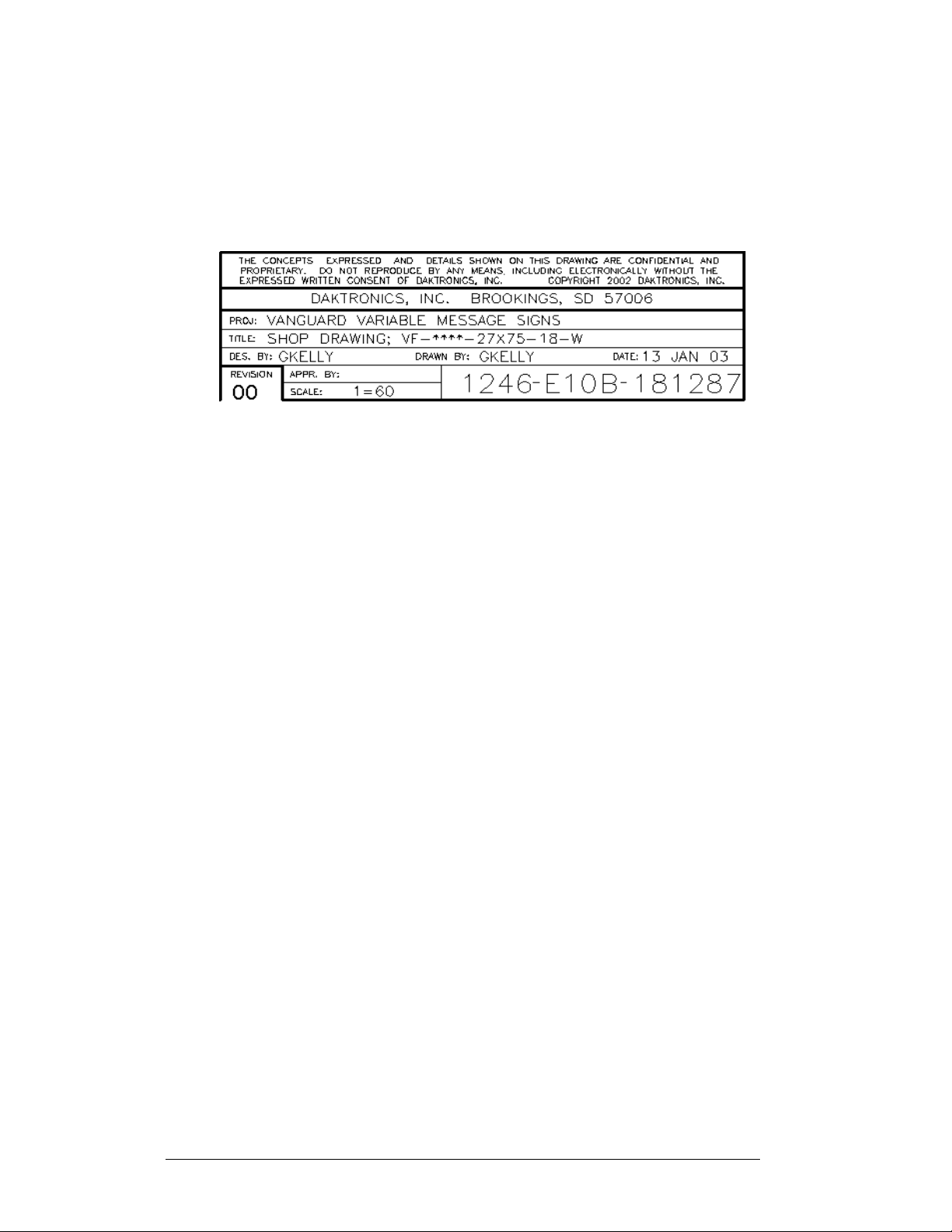
Figure 1 below illustrates the Daktronics drawing label. The drawing number is
located in the lower-right corner of the drawing. Listing the last set of digits and the
letter preceding them identifies drawings in the manual. In the example below, the
drawing would be referred to as Drawing B-181287. Reference drawings are
inserted after the section that references them.
Figure 1: Drawing Label
All reference s to drawing numbers, appendices , figures, or other manuals are
presented in bold typeface, as shown below.
“Refer to Drawing B-181287 in Appendix C for the power supply location.”
Additionally, drawings referenced in a particular section are listed at the beginning of
that section as seen in the following example:
Reference Drawing:
Shop Drawing; VF-****-27x75-18-W............................ Drawing B-181287
Daktronics signs are built for long life and require little maintenance. However, from
time to time, certain sign components will need replacing. The Replacement Parts
List in Section 4.13 provides the names and part numbers of components that may
need to be ordered during the life of the sign. Most sign components have a white
label that lists the part number. The component part number is in the following
format: 0P-_ _ _ _-_ _ _ _ (component) or 0A-_ _ _ _-_ _ _ _ (multi-component
assembly).
Following the Replacement Parts List is the Daktronics Exchange and Return
and Repair Programs in Section 4.14. Refer to these instructions if any sign
component needs replacement or repair.
1.2 Safety Precautions
Important Safeguards:
1. Read and understand these instructions before installing.
2. Be sure the sign is properly grounded with an earth ground electrode at the
display.
3. Disconnect power when servicing the sign.
4. Do not modify the sign structure or attach any panels or coverings to the
sign without the written consent of Daktronics, Inc.
1-2
Introduction
Page 11

1.3 Network Concepts
The concept of using LED displays as a cost effective, high impact method of
communication is rapidly growing throughout many industries and businesses. The
reasons for this growth are many, but the need for additional features and the
complexity of multiple sign installations has emerged. Daktronics display systems
have been designed to meet those needs. The common thread to most client requests
is a means of programming and controlling a group of signs from a central control
point. Daktronics responded by developing a power system of interconnecting and
controlling signs. Great care has been taken to design products that will satisfy a wide
variety of installations. Some of the design goals of these systems include the
following:
· Easy transfer of messages
· The ability to tell a sign or group of signs in the network which message
should run
· The ability to determine the status of any sign on the network
· The ability to control multiple sign technologies on the same network
All the programming features would seem insignificant if the systems could not be
accomplished with basic tools and without technical difficulty. Daktronics decided to
use the very popular and readily available RJ11 connector. This connector is also
used on modern home and office telephone equipment.
All that is required for signal installation is standard six (6)-conductor modular
telephone wire and a tool to install the connector. Tools required for mounting the
display depend on the location and size of the display. For some installations, it may
be possible to purchase pre-terminated telephone cables for use with the displays.
There are four (4) network systems available: RS232, RS422, modem, and fiber
optic.
RS232 Network
RS232 (EIA/TIA-232-E) is a standard communication interface that employs a
single-ended serial transmission scheme that uses a maximum cable length of 8
meters (25 feet). This interface was designed for computer communication at short
distances. All computers have an RS232 communications port. Refer to Section 3 for
additional information.
RS422 Network
RS422 (EIA/TIA-422-B) is a standard communication interface that utilizes a
differential balanced transmission scheme, which uses a typical maximum cable
length of 1.2 km (approximately 4,000 feet). The main advantage of RS422 over
RS232 is the longer cable length that is possible. A signal converter is needed to
convert the computer’s RS232 to RS422. Refer to Section 3 for additional
information.
Introduction
1-3
Page 12

Modem Network
The modem is a standard communication interface that utilizes standard phone
transmission lines. The phone company assigns each phone line a number that the
modem uses to communicate between the control computer and display. Refer to
Section 3 for additional information.
Fiber Optic Network
A fiber optic network is a standard communication method transmitting light (signal)
through a glass fibe r. Fiber optic cable has a maximum length of 2 ,000 feet. A signal
conductor is needed to convert the computer’s RS232 to fiber optic signal. Refer to
Section 3 for additional information.
Radio Network
The radio network is a standar d communication method tha t uses radio waves at high
frequencies to transmit signal. The Venus 1500 Radio network has a maximum
distance of 1,500 feet outdoor and 500 feet indoor. A nearly straight line-of-sight
path must be maintained between the Server Radio connected to the computer and the
Client Radio connected to the display. Refer to Section 3 and the radio manual
(ED-13932) for additional information.
1.4 Display Overview
Reference Drawing:
Shop Drawing...........................................................Refer to Appendix C
The Daktronics outdoor LED displays have been designed and manufactured for
performance, reliability, easy maintenance, and long life. The displays consist of an
array of LED pixels. The configuration of LED pixels is dependent on the family of
LED displays.
A typical display system consists of a Windows
running Venus
single-face units, which are single-sided stand-alone displays. They can become
double-faced by mounting them back-to-back with a second unit.
®
Venus
2000, or XP Home/Professional operating systems on an IBM
computer. Refer to the Venus
installation and operation of the Venus
Refer to Section 4 for the summaries of how signal and power are routed through the
displays.
â
1500 software and one or more displays. The displays are offered as
1500 is a software package that runs under Windowsâ 98, ME™, NT® 4.0,
®
1500 controller operator’s manual (ED-13530) for
â
based personal computer (PC)
â
-compatible
®
1500 controller editing station.
1-4
Introduction
Page 13
The Galaxy Series AF-3010 displays are matrix-based outdoor LED displays, which
are available in monochrome red characters. They are offered as 8 pixel high displays
with a standard 7 high 9", 16 high 21" character, or 24 high displays with a standard
7 high 9", 1 5 high 20", or 24 high 32 "characte r in six (6) different lengths. The
Galaxy model numbers are described as follows: AF-3010-RRxCCC-9-R.
AF-3010 =
RR =
CCC =
9 =
R =
Outdoor Galaxy® Display
8, 16, or 24 Rows High
Number of Columns Long (48, 64, 80, 96,
112, and 128 are available)
9" Character Height
Monochrome Red
1.5 Component Identification
The following illustrations depict some of the more commonly accessed Galaxy sign
components. Because Daktronics occasionally alters standard design to meet
customer needs, the actual sign design may vary slightly from the illustrations below.
This is only a brief overview. Refer to Section 4 for more detailed information on
maintaining and troubleshooting various sign components.
Com Port: Connector on the back of the control computer. The COM port is used to
control the sign network through either a 9- or a 25-p i n serial connector. The
computer requires a serial port to work with this display.
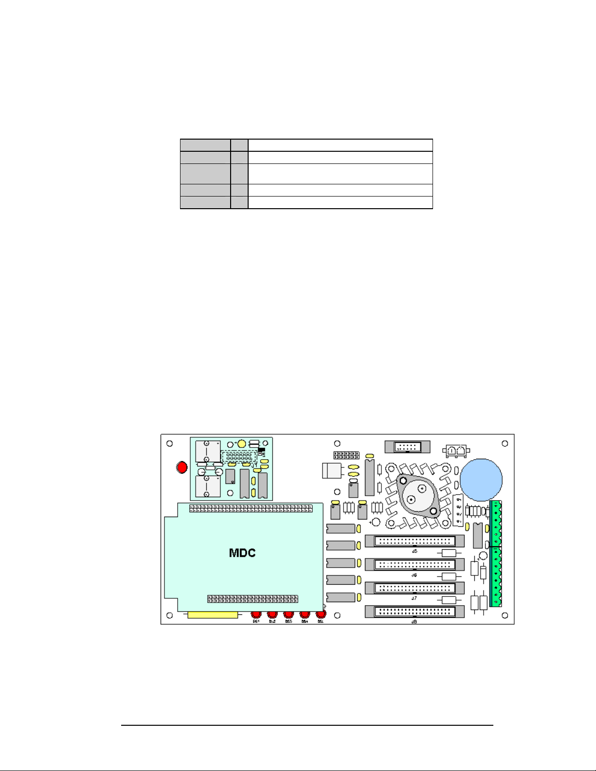
Controller: “Brains” of the sign. The controller receives, translates, and activates the
signal information from the control computer to the appropriate pixels on the sign
accordingly.
Figure 2: MDC Controller
Driver/Pixel Board: Responsible for the switching and intensity levels of the LEDs.
The LED pixels are mounted directly onto the pixel board. The driver is located on
the back of the display board.
Introduction
1-5
Page 14
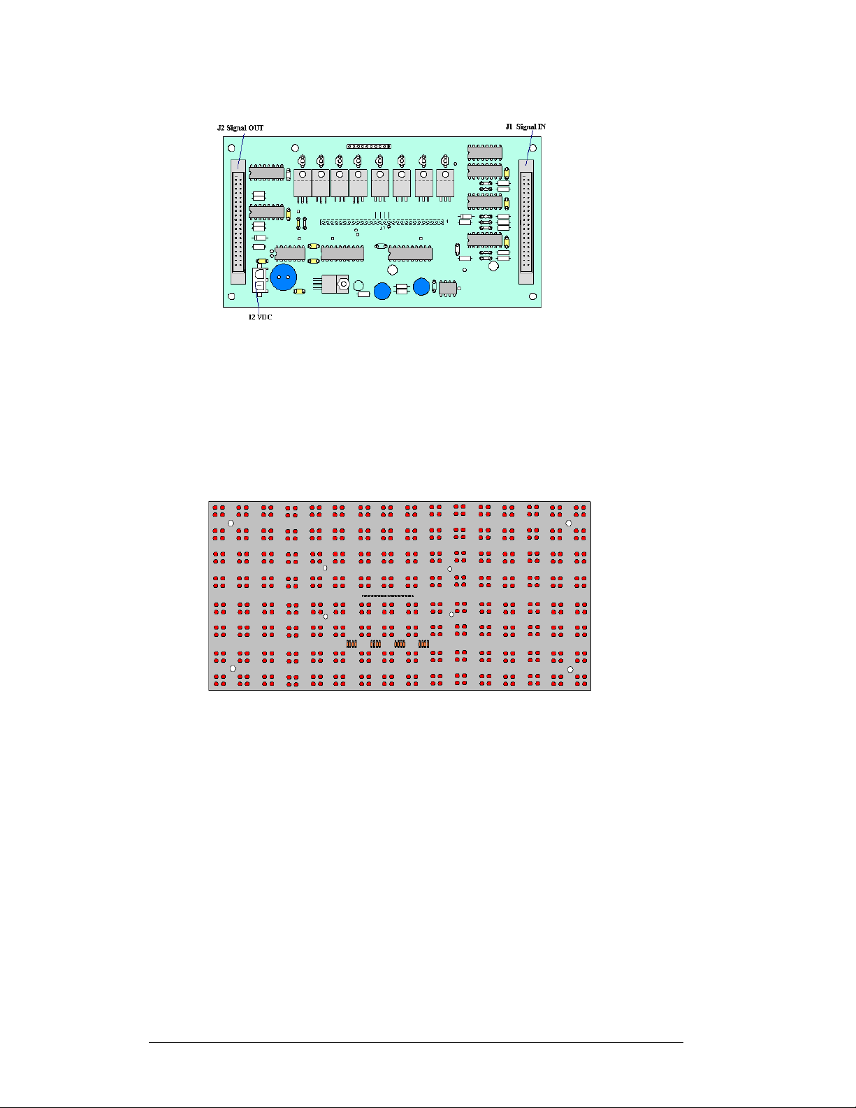
Figure 3: AF-3010 Driver/Pixel Board
Galaxy: Daktronics trademarked name for LED monochrome or tri-colored matrix
signs.
LED (light emitting diode): Low energy, high intensity lighti ng uni ts.
Module: 8 pixels high by 16 pixels wide. Each is individually removable from the
front of the sign.
1-6
Figure 4: 8x16 Pixel Module
Network: Consists of multiple signs connected to each other. Up to 240 Venus 1500
controlled displays can exist on one network.
Pixel: Cluster of four LEDs. The number and color of the LEDs depends on sign
application.
Power Supply: Converts AC line voltage from the load center to low DC voltage for
one or more module driver boards.
RS232: Standard PC communication type with a maximum cable length of 25 feet
(7.62 meters).
RS422: Standard differential communication type with a maximum cable length of
4,000 feet (1.2 kilometers).
Sign Address: Identification number assigned to each sign of a network. Flipping
DIP switches on the controller sets the sign address. The control software uses the
Introduction
Page 15
address to locate and communicate with each sign, but signs on the same network
cannot have the same address.
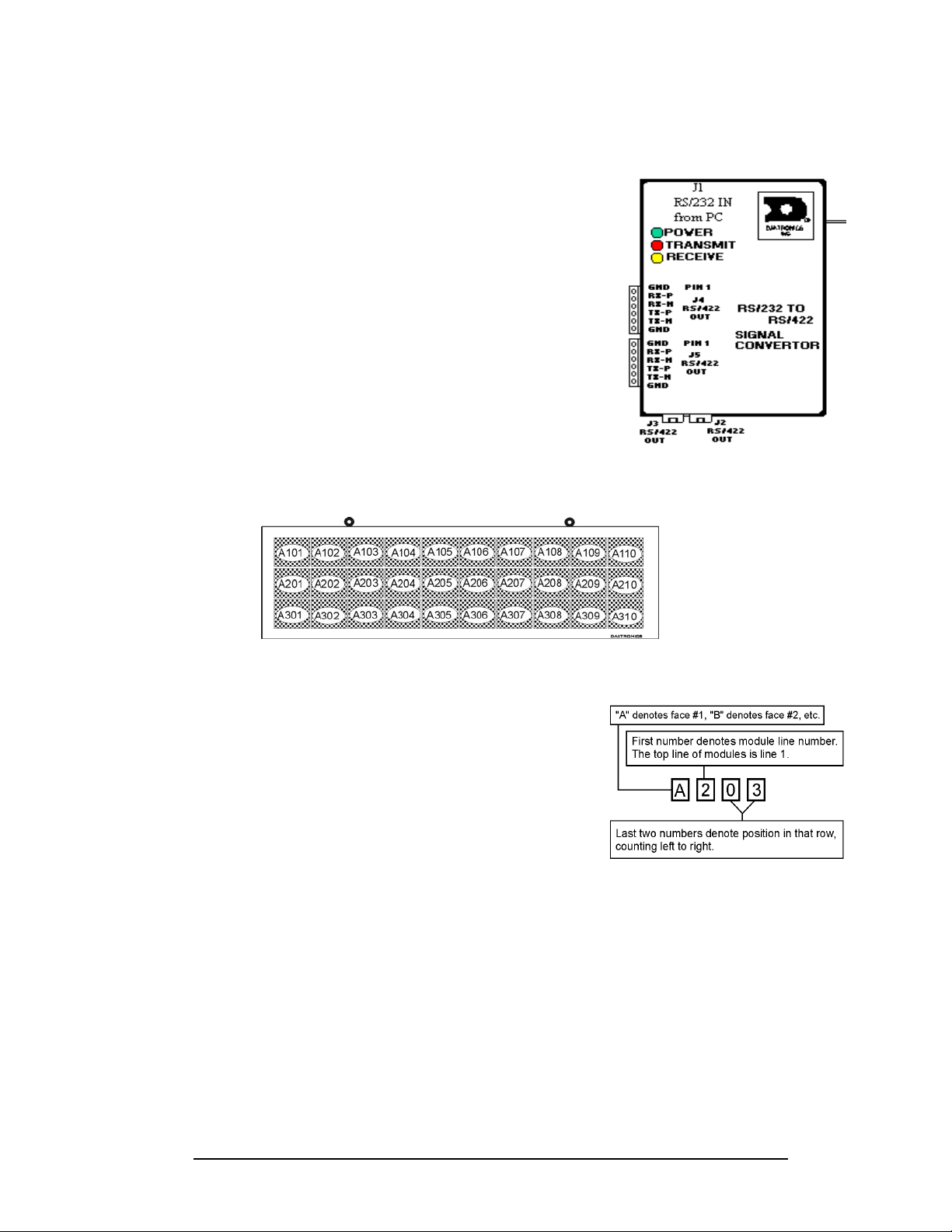
Signal Converter: Daktronics supplied unit that
converts the data from RS232 to RS422, or RS232 to
fiber optic signal. The signal converter is connected to
the control PC via straight though serial cable.
1.6 Daktronics Nomenclature
Figure 5: Signal Converter
Figure 6: Module Numbering Example – 24x160 Front
To fully understa nd some Daktronics drawings, such
as schematics, it is necessary to know how various
components are labeled in those drawings. This
information is also useful when trying to
communicate maintenance or troubleshooting
efforts.
A module is the building block of the Galaxy sign.
Each module measures 8 pixels high by 16 pixels
wide. By placing modules side-by-side and on top of
one another, a sign of any size can be designed and
built. Individual modules can be easily removed
Figure 7: Module Numbering
from the sign if required. Figure 6 above illustrates
how Daktronics numbers modules on a Galaxy sign.
Figure 7 on the right breaks down the module
numbering method.
The label “A” on a drawing typically denotes an assembly. An assembly can be a
single circuit board or a collection of components that function together, usually
mounted on a single plate or in a single enclosure. Assemblies are divided into two
types: those that route signal and those that route power.
Introduction
1-7
Page 16

In addition, the following labeling formats might be found on various Daktronics
drawings:
· “TB_ _” represents a termination block for power or signal cable.
· “F_ _” stands for a fuse.
· “E_ _” indicates a grounding point.
· “J_ _” symbolizes a power or signal jack.
· “P_ _” identifies a power or signal plug for the opposite jack.
Finally, Daktronics part numbers a re commonly found on dr awings. Those part
numbers can be used when requesting replacement parts from Daktronics Customer
Service. T ake note of the following part number formats:
· “0P-_ _ _ _-_ _ _ _” denotes an individual circuit board, such as a driver
board.
· “0A-_ _ _ _-_ _ _ _” represents an assembly, such as a circuit board and the
plate or bracket to which it is mounted. A collection of circuit boards
working as a single unit may also carry an assembly label.
· “W-_ _ _ _” shows a wire or cable. Cables may also carry the assembly
numbering format in certain circumstances. This is especially true of ribbon
cables.
· “F-_ _ _ _” indicates a fuse.
Most circuit boards and components within this sign carry
a label that lists the part number of the unit. If a circuit
board or assembly is not listed in the Replacement Parts
List in Section 4.13, use the label to order a replacement.
A typical label is shown in Figure 8 on the right. The part
number is in bold.
0P-1195-0001
SN: 6343
05/19/99 REV.1
Figure 8: Typical Label
1-8
Introduction
Page 17
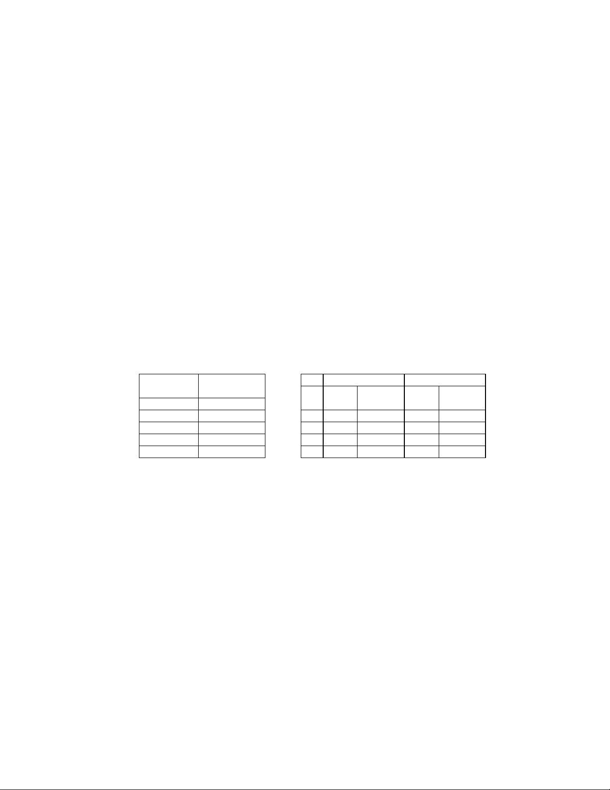
Eyebolts
Almost every display that leav es D ak tronics is equipped w ith ey ebolts for lifting the display . There are
two standard sizes of eyebolts: ½″ and A″.
Load Increase Factor: The load increases as the lift angle (θ) decreases. The allowable load on the
eyebolts also decreases with the lift angle due the bending stress on the eyebolts. In sum, the smaller
the angle between the cable and the top of the display, the lighter the sign must be to safely lift it. Do
NOT attempt to lift the display when the lift angle is less than 30 degrees.
Horizontal Load Angle
Angle Factor (L/H)
90 1.00
60 1.155 90 2600 2600 4000 4000
50 1.305 60 1500 1299 3300 2858
45 1.414 45 650 460 1000 707
30 2.00 30 520 260 800 400
θθθθ
½”
Line Weight/ Line Weight/
Load Anchor Load Anchor
A
A”
AA
ED7244 Copyright 1996-2001
Rev. 4 – 14 March 2001 Daktronics, Inc.
Page 18
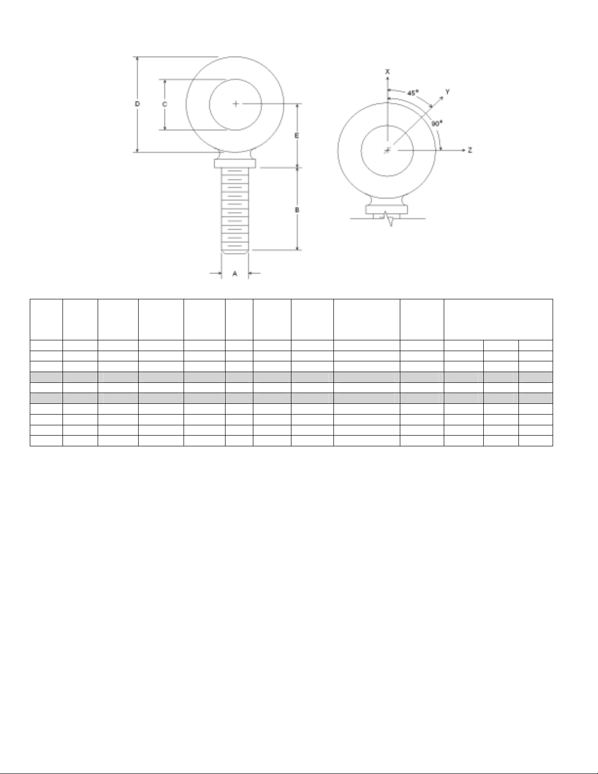
Min.
A B C D E No.
Wx Wy Wz
1/4 1 3/4 1-3/16 25/32 21 600 2,000 Blank 1/4-20 7/8 400 100 80
3/8 1-1/4 1 1-21/32 1-3/16 23 2,100 5,000 Blank 3/8-16 1-1/8 1,400 350 250
1/2 1-1/2 1-3/16 2-1/16 1-13/32 25 3,900 9,200 Blank 1/2-13 1-11/32 2,600 650 520
9/16 1-5/8 1-9/32 2-13/16 1-17/32 26 4,500 11,830 Blank 9/16-12 1-3/8 3,000 750 600
5/8 1-3/4 1-3/8 2-1/2 1-11/16 27 6,000 14,700 Blank 5/8-11 1-9/16 4,000 1,000 800
3/4 2 1-1/2 2-13/16 1-13/16 28 9,000 21,700 Blank 3/4-10 1-5/8 6,000 1,500 1,200
7/8 2-1/4 1-11/16 3-1/4 2-1/16 29 10,000 30,000 Blank 7/8-9 1-13/16 6,600 1,670 1,330
1 2-1/2 1-13/16 3-9/16 2-5/16 30 12,000 39,400 Blank 1-8 2-1/16 8,000 2,000 1,600
1-1/2 3-1/2 2-9/16 5-1/2 3-5/32 34 27,000 91,300 Blank 1-1/2-6 3 17,800 4,500 3,600
Proof
Load
(lbs.)
Min.
Break
Load
(lbs.)
Stocked
Min.
Eff.
Thrd.
Length
Line Loads
A. Do not use eyebolts on angular lifts unless absolutely necessary. For angular lifts, the shoulder pattern
eyebolt is preferred.
B. Load should always be applied to eyebolts in the plane of the eye, not at some angle to this plane.
C. Shoulder eyebolts must be properly seated (should bear firmly against the mating part), otherwise the
working loads must be reduced to those indicated for regular eyebolts. A washer or spacer may be
required to put the plane of the eye in the direction of the load when the shoulder is seated.
D. No load greater than the safe working load listed in the data table should be used.
E. To obtain the greatest strength from the eyebolt, it must fit reasonably tight in its mounting hole to prevent
accidental unscrewing due to twist of cable.
F. Eyebolts should never be painted or otherwise coated when used for lifting. Such coatings may cover
potential flaws in the eyebolt.
G. To attain the safe working loads listed for regular eyebolts, 90% of the thread length must be engaged.
Copyright 1996-2001 ED-7244
Daktronics, Inc. Rev. 4 – 14 March 2001
Page 19

Section 2: Mechanical Installation
Note: Daktronics does not guarantee the warranty in situations where the sign is not consta ntly
in a stable environment.
Daktronics engi neering staff must approve any changes that may affect the weather-tightness
of the sign. If any modifications are made, detailed drawings of the changes must be
submitted to Daktronics for evaluation and approval, or the warranty may be void.
Daktronics is not responsible for installations or the structural integrity of support
structures done by others. It is the customer’s responsibility to make sure that a qualified
structural engineer has ensured the structure and any additional hardware.
2.1 Mechanical Installation Overview
Because every installation site is unique, there is no single Daktronics-approved
procedure for mounting the Galaxy signs. The information contained in this section is
general information only and may or may not be appropriate for your particular
installation.
A qualified individual must make all decisions regarding the mounting of this
sign.
Read both the mechanical and electrical installation sections of this manual
before beginning any installation procedures.
2.2 Support Structure Design
Support structure design depends on the mounting methods, sign size, and weight.
The structure design is critical and should be done only by a qualified individual.
Sign height and wind loading are also critical factors. It is the customer’s
responsibility to ensure that the structure and mounting hardware are adequate.
Daktronics is not responsible for the installations or the structural integrity of
support structures done by others.
It is the installer’s responsibility to ensure the mounting structure and
hardware are capable of supporting the sign, and will agree with local codes.
Before beginning the installation process, verify the following.
· The mounting structure will provide a straight and square-mounting frame
for the sign.
· The mounting structure is capable of supporting the sign and will not yield
at any unsupported points after mounting.
Correct any deficiencies before installation.
Mechanical Installation 2-1
Page 20
2.3 Display Ventilation Requirements
Reference Drawing:
Shop Drawing...........................................................Refer to Appendix C
Fans are mounted inside the back of the display for cooling. Fresh air inlets and
exhaust vents should not be obstructed in any way (refer to shop drawings located in
Appendix C). Using the Daktronics suggested mounting methods will ensure proper
ventilation. Fans turn ON when the interior display temperature reaches 140º F.
Consult a Daktronics sales representative for clearance requirements regarding your
particular display if you are using a different mounting method. If ventilation
requirements are not met, the display warranty will be void.
2.4 Mounting Kit
A mounting kit is available when ordering a display. The mounting kit includes the
hardware to either mount the display on a pole or on a wall. When using a Daktronics
mounting kit, refer to the instructions in Section 2.5.
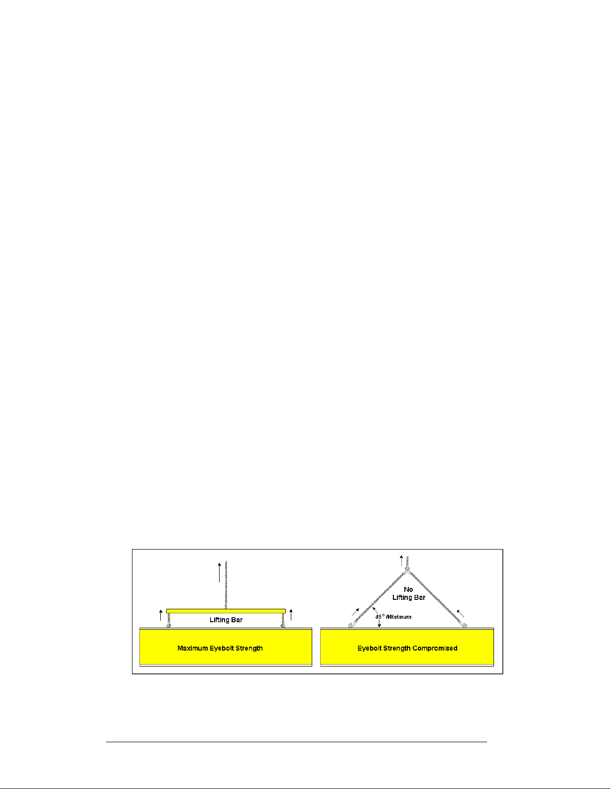
2.5 Display Lifting
Reference Drawing:
Shop Drawing...........................................................Refer to Appendix C
Eyebolts are provided on the top of each display for lifting purposes. Refer to
ED-7244 at the end of this section for the proper lifting procedure. A spreader bar
should be used to maintain a vertical force on each eyebolt. Using cables or chains to
attach the eyebolts directly to the central lifting point can apply dangerous lateral
force to the eyebolts. Do not use the eyebolts for permanent installation. Refer to
shop drawings for the dimensions of the eyebolts from each end of the display.
Once the display is permanently mounted, replace the eyebolts with the hex-head
bolts (supplied by Daktronics) and sealing washers used with the eyebolts. Use water
proofing compound, such as silicon, along with bolts and sealing washers, to ensure a
waterproof seal.
Figure 9: Lifting the Display (Correct, Left; Incorrect, Right)
2-2
Mechanical Installation
Page 21

2.6 Display Cabinet Mounting
Reference Drawings:
Mounting Drawing, AF-3010-*****-9-*...........................Drawing A-102469
Shop Drawing................................................................Refer Appendix C
It is the customer’s responsibility to ensure that the installation will meet local
standards. The mounting hardware must be capable of supporting all components to
be mounted. The mounting hardware and method are the responsibility of the
customer. Refer to shop drawings located within Appendix C for the approximate
weight and size of each model of display. Daktronics is not responsible for the
installations or the structural integr ity of support structures done by others.
Daktronics has recommendations fo r both a wall mount method and a pole mount
method. R emember to have all mounted displays inspected by a qualified structural
engineer.
Note: The display has hinged face panel. Care must be taken to allow the door to
properly open (refer to Drawing A-102469).
Wall Mount
Note: Because each site differs, the Daktronics wall mount kit is not a complete
installation kit. It is the customer’s responsibility to determine the proper wall
mounting method and location.
Refer to Drawing A-102469 for a suggested wall mount method. The wall mounting
channels are attached to the rear of the display by Daktronics. Notice that the vertical
distance between the mounting channels is 21". The number of attachment points
needed and the wall structure must be reviewed by a qualified structural engineer and
meet all national and local codes.
Pole Mount
Refer to Drawing A-102469 for a suggested pole mount method. The locati on of the
poles needs to be determined by the customer. The number of poles needed and the
pole structure and footings must be reviewed by a qualified structural engineer and
meet all national and local codes.
One (1) Dakt ronics provi ded mounting kit includes:
· Clamping Channel (qty. 2, attached to rear of display by Daktronics)
· Clamping Angles (qty. 4)
· 1/2" Threaded Rod (qty. 8)
· 1/2" Nut (qty. 16)
· 1/2" Lock Washer (qty. 16)
Mechanical Installation 2-3
Page 22

Study the illustration of the pole mounting method in Drawing A-102469, and then
use the following procedure for each display:
1. Measure the beam spacing and drill a 9/16" diameter hole for each 1/2"
threaded rod through one flange of the clamping channels.
2. Insert the threaded rods through the drilled opening and secure using 1/2"
nuts and lock washers.
3. Position the display at the front of the beams with the threaded rods
extending from the rear of the channels, straddling the poles.
4. Raise the display to the desired height.
5. Slide clamping angles over the ends of the threaded rods and loosely install
1/2" washers and nuts.
6. Make final adjustments in positioning the display. Make sure the threaded
rods are perpendicular to the display.
7. Tighten all the 1/2" hardware.
2-4
Mechanical Installation
Page 23

Section 3: Electrical Installation
Only a qualified individual should terminate power and signa l cable within this
Daktronics sign.
The Daktronics engineering staff must approve any changes made to the sign. Before altering
the sign, submit detailed drawings for the proposed modifications to the Daktronics
engineering staff for evaluation and approval, or the warranty will be rendered null and void.
3.1 Common Connectors in the Sign
The power and signal connections i n the signs use many different types of
connectors. Take special care when disengaging any connector so as not to damage
the connector, the cable or the circuit board.
When pulling a connector plug from a jack, do not pull on the wire or cable; pull on
the jack itself. Pulling on the wires may damage the cable and connector.
The following information presents some common connectors encountered during
sign installation and maintenance:
1. Ribbon Cable Connectors:
Figure 10 on the right illustrates a typical ribbon
connector. To disconnect the ribbon cable, push the plastic
clips on the sides of the jack to unlock and remove the
cable.
Before replacing a ribbon cable connector, spray it with
DeoxIT
may cause signal problems. In addition, apply a generous
amount of CaiLube
inserting it into the jack. This paste will protect both the
plug and the jack from corrosion.
2. Termination Blocks:
Termination blocks are usually used to connect internal
power and signal wires to wires of the same type coming
into the sign from an external source. Power wires need to
have one-half inch of insulation stripped from the end of
the wire prior to termination. Tighten all screws firmly to
ensure a good electrical connection. Refer to Figure 11 on
the right.
™
contact cleaner to remove any foreign matter that
™
protector paste to the plug before
Figure 10: Ribbon
Cable Connector
Figure 11: Termination
Block
Electrical Installation 3-1
Page 24

3. Phoenixä-Style Connectors:
Phoenix-style connectors, which are usually green, are often
used for signal termination on circuit boards. Refer to Figure
12 on the right. Strip one-quarter inch of insulation from the
wire prior to termination. To remove a wire, turn the above
screw counter-clockwise to loosen the connector's grip on the
wire. To insert a wire, push the bare wire into the connector,
and turn the above screw clockwise to lock the wire into
place.
4. Mate-n-Lokä Connectors:
The Mate-n-Lok connectors found in the signs are white and
come in a variety of sizes. Figure 13 on the right illustrates a
four-pin Mat e-n-Lok connector. To remove the plug fo rm the
jack, squeeze the plastic locking clasps on the side of the
plug and pull it from the jack.
Figure 12: Phoenix-
Connector
Style
5. Phone Jacks (RJ11/RJ45 Connectors):
RJ connectors are similar to the telephone connectors found
in homes and are used on the ends of RJ11 or RJ45 cable. In
order to remove this plug from the jack, depress the small
clip on the underside of the plug. Before replacing an RJ
connector, spray it with DeoxIT
any foreign matter that may cause signal problems. In
addition, apply a generous amount of CaiLube
™
contact cleaner to remove
™
protector
paste to the plug before inserting it into the jack. This paste
will protect both the plug and the jack from corrosion.
3.2 Control Cable Categories
The conductor connector used in the network is an industry standard,
6-pin RJ11. This connector can be found on
many telephones and LANs.
The cable used in the network is a standard flat
six-conductor telephone cable (standard flipped
cable). Refer to Figure 14 on the right. This
cable has one end that is the mirror image of the
other end (i.e. the cable is flipped). Refer to
Figure 15 on the following page for a standard
flipped cable.
Figure 13: Mate-nLok Connector
Figure 14: 6-Conductor RJ11 Connector and
Cable
3-2
Electrical Installation
Page 25

Notice below in Figure 15 that the color code on one connector must be made the
opposite on the other connector. When installing a network, it is not easy to
remember in which direction the previous end was oriented. One simple way to avoid
confusion is to standardize the color code, having one color for the connector going
into the output of a sign, and the opposite color for a connector going into the input
of a sign. This will help ensure correct cabling since cables are always installed from
the output jack of one sign to the input jack of the next sign.
Figure 15: Flipped Cable with RJ Connectors
3.3 Conduit
Reference Drawings:
System Riser Diagram, Modem ..................................... Drawing A-88426
Power/Signal Termination Panel....................................Drawing A-88427
System Riser Diagram, RS422......................................Drawing A-92681
System Riser Diagram, RS232......................................Drawing A-96058
System Riser Diagram, Fiber.......................................Drawing A-110559
System Riser Diagram, Outdoor Radio, Gen 2............Drawing A-185325
Shop Drawing............................................................Refer to Appendix C
Daktronics does not include the conduit. Knockouts will be provided for power and
signal. Separat e conduit must be used t o route:
· Power
· Signal IN wires
· Signal OUT wires (if signal is required for another display)
The conduit holes are located at the bottom right (rear view) of the back of the
display (refer to shop drawings located within Appendix C).
To access the knockouts, release the face panel latches using an 8mm Allen wrench
(provided by Daktronics). Open the face panel. Caution: The door will swing up.
Remove the bottom left module (front view) to reach the knockouts (refer to Section
4.3 to remove a module).
Punch or drill out the desired knockouts. Be careful that none of the internal
components are damaged. Attach the conduit and route the power and signal cables.
Refer to Drawing A-88427 for a picture of the power and signal termination panels.
For displays with more than one face, signal and temperature sensor wiring between
displays can be r outed through the same conduit.
Electrical Installation 3-3
Page 26

3.4 Grounding
Displays must be grounded according to the provisions outlined in Article 250 of the
National Electrical Code
®
. Daktronics recommends a resistance to ground of 10
ohms or less. The electrical contractor who is performing the electrical installation
can perform verification of ground resistance. Daktronics Sales and Service
personnel can also perform this service.
The display system must be connected to e arth-ground. Proper grounding is
necessary for reliable equipment operation. It also protects the equipment from
damaging electri cal disturba nces and lightning. The display must be properly
grounded or the warranty will be void.
The material of an earth-ground electrode differs from region to region and from
conditions present at the site. Consult the National Electrical Code and any local
electrical codes that may apply. The support structure of the display cannot be used
as an earth-ground electrode. The support is generally embedded in concrete, and if
in earth, the steel is either primed or it corrodes, making it a poor ground.
Power Installation
There are two considerations for power installation: installation with ground and
neutral conductors provided, and installation with only a neutral conductor provided.
These two power installations differ slightly, as described in the following
paragraphs:
Ins allation w th Ground and Neutral Conductors P ovided t i r
For this type of installation, the power cable must contain an isolated earth-ground
conductor. Under this circumstance, do not connect neut ral to ground at the
disconnect or at the display. This would violate electrical codes and void the
warranty. Use a disconnect so that all hot lines and neutral can be disconnected.
Refer to Figure 16 below for installation details. The National Electrical Code
requires the use of a lockable power disconnect within sight of or at the display.
3-4
Figure 16: Installation with Ground and Neutral Conductors Provided
Electrical Installation
Page 27

Ins allation w th Only a Neutral Conductor Providedt i
Installations where no grounding conductor is provided must comply with article
250-32 of the National Electrical Code. If the installation in question meets all of the
requirements of article 250-32, the following guidelines must be observed:
· Connect the grounding electrode cable at the local disconnect, never at the
display power termination panel.
· A disconnect tha t opens all of the ungrounded phase conductors should be
used.
· The neutral and the ground conductors should be bonded in the display
power termination panel.
Refer to Figure 17 below for installation details.
Figure 17: Installation with Only Neutral Conductor Provided
3.5 Control Cable Requirements
RS232
This cable is a 2-conductor shielded cable used to transmit an RS232 signal
(Daktronics part number W-1117). This unshielded cable should not be subjected to
mechanical flexing after installation. This cable is not for direct burial and should be
routed in a dedicated, grounded, metallic conduit at the base of the display structure.
This cable has a maximum length of 25 feet.
Electrical Installation 3-5
Page 28

RS422
This cable is a 6-conductor shielded cable used to transmit an RS422 signal
(Daktronics part number W-1210). This unshielded cable consists of un-paired wires.
They should not be subjected to mechanical flexing after installation. This cable is
not for direct burial and should have one of the following routings:
· In dedicated metallic conduit
· Inside buildings - if cable is not in conduit, keep away from interference
signals
With interference signals, such as power conductors, intercom, etc., typically a twofoot separation is required.
Modem
The modem option will use a standard tele phone cable routed through a conduit. The
local telephone company will need to assist in this installation.
Ask the telephone company which colors the TIP uses, and the RING for signal hook
up.
Note: The telephone lines must be dedicated lines and not run through a switch
board/communications system.
Fiber Optic
This cable is a 4-fiber cable (Daktronics part number W-1376). Two fibers are used
for display communications and the other two are saved for spares. The cable may be
either direct burial or routed in conduit but it should not be subjected to mechanical
flexing.
3-6
Radio
The Server radio connected to the computer requires an 18-gauge six-c onductor
cable (Daktronics part number W-1370). Four-conductors will be used for the signal
and two for power. These wires need to be in conduit when exposed to outdoor
conditions to the Server radio. The maximum distance from the J-box to the Server
radio is 1,000 feet (305.8 meters).
The Client radio at the display comes with cable that is rated for outdoor use and
does not need to be in conduit. The cable should be secured to the structure so it does
not come loose from the display.
Electrical Installation
Page 29

3.6 Signal Termination from Computer to Di spl a y
Reference Drawings:
System Riser Diagram, Modem ..................................... Drawing A-88426
System Riser Diagram, Power/Signal V1500 Displays..Drawing A-88427
System Riser Diagram, RS422......................................Drawing A-92681
System Riser Diagram, RS232......................................Drawing A-96058
System Riser Diagram, Fiber.......................................Drawing A-110559
System Riser Diagram, Outdoor Radio, Gen 2............Drawing A-185325
RS232
One end of the signal cable should be terminated to the 10 position terminal block in
the display labeled “IN RS232” (TB42). Drawing A-88427 is an example of the
termination panels. The opposite end is terminated at the J-box at the display
structure. The laptop PC connects to the J-box through the serial cable (refer to
Drawing A-96058).
Figure 18: RS232 Connections
J-Box Field Cabling Terminal Block (Data In)
- - Pin 1 (N.C.)
- - Pin 2 (N.C.)
Pin 2 (RX-P) Clear Pin 3 (TX-P)
Pin 3 (GND) Shield Pin 4 (GND)
Pin 1 (TX-P) Black Pin 5 (RX-P)
- - Pin 6 (N.C.)
Electrical Installation 3-7
Page 30

RS422
One end of the signal cable should be terminated to the surge suppressor terminal
block in the display labeled “IN RS422” (TB1). Drawing A-88427 is an example of
the termination panel. The opposite end is terminated at the signal converter
(Daktronics part number 0A-1127-0237). Refer to Drawing A-92681 shows an
example system riser using the RS422 signal termination.
Figure 19: RS422 Signal Converter Connections
Signal Converter (J4/J5) Field Cabling Terminal Block (Data In)
Pin 1 (GND) Red Pin 1 (GND)
Pin 2 (RX-P) Black Pin 2 (TX-P)
Pin 3 (RX-N) Brown Pin 3 (TX-N)
Pin 4 (TX-P) White Pin 4 (RX-P)
Pin 5 (TX-N) Blue Pin 5 (RX-N)
Pin 6 (GND)
Green Pin 6 (GND)
Shield (Bare) N.C.
3-8
Electrical Installation
Page 31

Modem
Terminate the signal telephone wires to the 10 position terminal block labeled “IN
MODEM” (TB42) as follows:
Figure 20: Modem Signal Connections
Telephone Wires Terminal Block
N.C. Pin 1
N.C. Pin 2
TIP-P Pin 3
Ring-P Pin 4
N.C. Pin 5
N.C. Pin 6
Drawing A-88426 shows an example modem system setup.
Fiber Optic
Route conduit and fiber cable from the PC to the left end of the master display.
Continue routing fiber to the controller box. Refer to Drawing A-110559 for an
example fiber system layout.
Connect fiber to J2 and J3 at the signal converter end (0A-1127-0239) ·
· Connect fiber to J4 and J5 at the display end
Electrical Installation 3-9
Page 32

Figure 21: Fiber Optic Layout
Signal Converter Field Cabling Display Fiber Board
J2 Transmit (TX) (color varies) J5 Receive (RX)
J3 Receive (RX) (color varies) J4 Transmit (TX)
Radio
A display that is controlled using a radio requires a server radio connected to the
control computer and a client radio at the display. The radios must be in line-of-sight
with each other.
1. Connect a DB9M to DB9 serial cable from the computer to the J-box. Use
6-condutor, 18-gauge cable, to connect from the J-box to the Server radio.
The cable must be in conduit when exposed to outdoor conditions. The
distance from the J-box to the Server radio should not exceed 1000 feet.
Figure 22 on the following page shows the connections from the J-box to
the server radio.
2. Route the cable provided with the Client radio into t he display through one
of the knockouts on the back of the display. Terminate the three signal
wires, and connect the power plug from the Client radio to the additional
jack in the display. Figure 23 on the following page shows the connection
from the client radio to the display.
3. Refer to Drawing A-185325 and the radio manual (ED-13932) for the
correct cable terminations.
3-10
Electrical Installation
Page 33

Figure 22: J-box to Server Radio Connections
Figure 23: Client Radio to Display Connections
Electrical Installation 3-11
Page 34

3.7 Signal Termination Between Two (or More) Displays
Reference Drawings:
System Riser Diagram, Modem......................................Drawing A-88426
System Riser Diagram; Power/Signal, V1500 Displays..Drawing A-88427
System Riser Diagram, RS422.......................................Drawing A-92681
System Riser Diagram, RS232.......................................Drawing A-96058
System Riser Diagram, Fiber .......................................Drawing A-110559
System Riser Diagram, Outdoor Radio, Gen 2 ............Drawing A-185325
RS422 Interconnection
This is the most common method of terminating signal between two or more signs. A
6-conductor cable is used and one end terminates at the “OUT RS422” 10-position
terminal block (TB43) on the first display. The other end terminates at the “IN
RS422” 10-position terminal block (TB42) in the second display.
3-12
Figure 24: RS422 Interconnection
Sign A
Data Out (TB43)
Pin 1 (GND) Green Pin 6 (GND)
Pin 2 (Data TX-N) Blue Pin 5 (Data RX-N)
Pin 3 (Data TX-P) White Pin 4 (Data RX-P)
Pin 4 (Data RX-N) Brown Pin 3 (Data TX-N)
Pin 5 (Data RX-P) Black Pin 2 (Data TX-P)
Pin 6 (GND)
Field Cabling
Sign B
Data In (TB42)
Red Pin 1 (GND)
Shield (Bare) N.C.
Electrical Installation
Page 35

Fiber Interconnection
A four-conductor fiber cable is used in connecting two or more displays in the Fiber
Interconnection method. Connect the fiber cable to the fiber cards of the display as
described on the following:
Sign A
Data Out (J2 and J3)
J2 (TX1) - J5 (RX2)
J3 (RX1) - J4 (TX2)
3.8 Initial Operation
When first operated, the display will run through an initialization in which it will
display the following:
1. Output Test (DDDs)
2. Product Name (Galaxy)
3. Display Size (Row x Column)
4. Firmware Number (ED10134)
5. Firmware Revision (Rev X.XX)
6. COM1 Configurati on (C1: V15/RTD)
7. COM2 Configuration (C2: None)
8. Line Frequency (6 0 Hz)
9. Hardware Address (HW: XX)
10. Software Address (SW: XX)
11. Display Name
12. Modem (if Present)
Field
Cabling
Sign B
Data In (J4 and J5)
Electrical Installation 3-13
Page 36

Page 37

Section 4: Maintenance and
Troubleshooting
Important Notes:
1. Disconnect power before any repair or maintenance work is done on
the display.
2. Qualified service personnel must make any access to internal display
electronics.
3. The Daktronics product manager’s engineering staff must approve any
changes that may affect the weather tightness of the display. This
includes, but is not limited to, the border shrouding and back sheets. If
ANY modifications are made to the weather tightness of the display,
detailed drawings of the changes MUST BE submitted to our
engineering staff for evaluation and approval or the warranty will be
null and void.
4. Care must be taken when handling the display’s face panel to prevent
injuries or damage, especially in windy conditions.
4.1 Weather Stripping
To ensure that the display is waterproof, weather stripping has been provided around
the entire display and around the face panel. It is important that the weather stripping
is installed properly at all times. Otherwise, water may leak into the display and
damage the components.
4.2 Module Numbering Convention
The following table shows the typical module numbering convention for a 16x64
display. A module is eight (8) pixels high by 16 pixels wide.
A101 A102 A103 A104
A201 A202 A203 A204
· Labeling reference begins with the upper left module and increments to the
right and down from that point, independent of display size.
· Modules are designated by the prefix “A.” A101 represents the upper left
module.
· T he hundreds digi t indicates the module line number. A101 through A104
make up the first module line, A201 through A204 make up the second line
and so forth.
Maintenance and Troubleshooting
4-1
Page 38

4.3 Display Access/Module Removal
To access the display’s interior electronic components, open the face panel and
remove the appropriate modules. The Galaxy displays are front access. Tools
needed: 8mm Allen wrench and 5/16" nutdriver
1. Release the face panel latches using an 8mm Allen wrench (provided by
Daktronics).
2. Open the face panel. Gas springs will hold the door open for servicing.
Caution: The door will swing up. Take extra precautions during windy
conditions.
3. Remove the four 5/16" mounting nuts hol ding the module to the display.
Each mounting nut is located in one corner of the module (refer to Figure
25 below on the left).
4. Carefully pull the module forward to unplug the power/signal connections
(refer to Figure 26 below on the right).
To install or replace the modules, follow the previous steps in reverse order.
Figure 25: Removing the Mounting Nuts
4.4 LED Driver Replacement
The LED driver is located on the rear side of the module: Tools needed: 8mm Allen
wrench and 5/16" nutdriver
1. Open the display, and release
the module.
2. Remove all power and signal
connection from the driver.
By pressing outward on the
locking tabs and gently
pulling the connector free, the
connectors are released (refer
to Figure 27 on the right).
3. Remove the four 5/16" nuts
from the corners. (Some
drivers are held in place by
plastic mounts.)
4-2
Figure 26: Removing the Module
Figure 27: Removing the Signal Connections
Maintenance and Troubleshooting
Page 39

4. Take note of the driver’s orientation.
5. Carefully remove the driver from the display board. Use an even amount of
force to prevent any damage due to bending of the connector pins on the
display board. Reverse the previous steps to replace the driver.
4.5 Power Supply
Reference Drawing:
Schematic .................................................................Refer to Appendix C
Note: Disconnect power from the display before removing a power supply.
The power supply is mounted behind every other module. The first power supply is
located behind module A102. This unit supplies power to the modules A101, A102,
A201, and A202. The remaining power supplies are located behind A103, A105,
A107, and A109, when applicable. One power supply connects to four (4) modules
(refer to schematics).
Refer to Section 4.3 for information on removing a module. Once the module has
been removed from the display: Tools needed: 8mm Allen wrench, 5/16"
nutdriver, and #2 Phillips screwdriver
1. Open the display and remove the module directing in front of the failed
power supply.
2. Disconnect the wires from the terminal block at the bottom of the power
supply. It helps to have the wires labeled for reconnecting them to the
power supply.
3. Use a Philips screwdriver to remove the power supply and bracket from the
vertical support.
4. Remove the screws securing the power supply to the bracket.
5. Attach the new power supply to the bracket using M4x8mm screws.
6. Attach the power supply/bracket assembly to the vertical support with #6
screws and washers.
7. Reconnect all wires to the power supply as shown in schematics.
Maintenance and Troubleshooting
4-3
Page 40

4.6 Controller Board
Reference Drawings:
System Riser Diagram, RS422.......................................Drawing A-92681
Shop Drawing...........................................................Refer to Appendix C
Accessing and Replacing the Controller Board
The controller board is located behind the bottom,
left module (refer to shop drawings). To access
the controller board: Tools needed: 8mm Allen
wrench, 5/16" nut driver, and 3/16" nutdriver
1. Open the display and remove the module
in front of the controller board (refer to
Section 4.3 to remove a module).
2. Remove all power and signal
connections from the board. Pressing
outward on the tabs, and carefully
pulling them from the jack releases the
“Locked” connectors.
3. Remove the mounting six screws using a
3/16" nutdriver.
4. Carefully remove the controller board
from the display.
Follow the previous steps in reverse order to
install a new controller board.
Figure 28: Controller Board
LEDs and Jumpers
The controller board contains three DIM, one Power, one RUN, and one Receive
Data LEDs.
The controller’s communication module contains two (2) jumpers for a modem
system. The jumpers must connect both pins for a modem system. For all other
applications, the jumpers must be removed.
Figure 29: LEDs and Jumpers
4-4
Maintenance and Troubleshooting
Page 41

Controller Address and Test Mode
Before a display can be run in a si gn network, it must
have an address. The display address can be set using
“DIP” switches located on a PC board known as the
MDC. The MDC is the circuit card mounted in the
lower right corner of the controller board.
Locate the DIP switches on the MDC. They should be
on the bottom end of the card. Refer to Figure 30 on
the right for a picture of the DIP switches.
When replacing a controller board, be sure to set the
DIP switches to the same address configuration as the
defective controller. The DIP switches follow standard
binary code.
Note: By setting the DIP switches to address 0 (flip all
the switches toward the numbers on the circuit board),
a test mode can be activated. The display’s power must
be downed, and then reconnected to run the test mode.
Switch 8 Switch 7 Switch 6 Switch 5 Switch 4 Switch 3 Switch 2 Switch 1 Address
Off Off Off Off Off Off Off On 1
Off Off Off Off Off Off On Off 2
Off Off Off Off Off Off On On 3
Off Off Off Off Off On Off Off 4
Off Off Off Off Off On Off On 5
Off Off Off Off Off On On Off 6
Off Off Off Off Off On On On 7
Off Off Off Off On Off Off Off 8
Off Off Off Off On Off Off On 9
Off Off Off Off On Off On Off 10
… … … … … … … …
Off On On On On On On On 127
Figure 30: Location of DIP
Switches
Maintenance and Troubleshooting
4-5
Page 42

Light Detector
Reference Drawings:
Shop Drawing.....................................................Refer to Appendix C
Schematic ..........................................................Refer to Appendix C
The light detector is internally mounted and wired at Daktronics. It is located on the
lower left of the display (refer to Detail A in shop drawings). A 4-conductor cable is
used to connect the light detector to the controller board. The cable is terminated at
the terminal block on the light sensor and at the terminal block on the controller
board (refer to schematics).
Light Detector
Pin No.
1 Green 3
2 White 4
3 Red 1
4 Black 2
N.C. Bare 2
4.7 Transformer
The transformer is used to provide power to the controller board 10-12 VAC,
modem, fiber converter, or radio depending on the communication method used. It is
located in the bottom left corner (front view) of the display in the power termination
box.
Cable Wires
Color
Controller Board
Pin No.
4.8 Modem
Accessing and Replacing the Modem
If a modem was included with the display, it is located inside the
sign next to the controller board. Tools required: 8mm Allen
wrench, 5/16" nutdriver, and 3/16" nutdriver
1. Open display and remove the module in front of the
modem in the lower left corner.
2. To replace a modem, first disconnect the power and
signal connections (refer to Figure 31 on the right for
the location of the power jack).
3. The modem is held in place with four 3/16" screws.
Remove these four screws and carefully remove the
modem.
4. Place the new modem over the four screws and replace
the screws. Reconnect the power and signal connections.
Figure 31: Modem
4-6
Maintenance and Troubleshooting
Page 43

LEDs and Jumpers
The modem module has two (2) LEDs. The Power LED should remain lit while
power is applied to the modem. The Active LED will light when the modem is in the
process of communicating.
A modem system requires jumpers to be set on the controller board. Refer to Section
4.6 for these jumper settings.
Fiber Board
The fiberboard has three LEDs. The power LED
(DS1) should remain lit while power is applied to
the module. The receive LED (DS2) will light
when the display fiberboard is accepting signal
from the fiber signal converter. The transmit LED
(DS3) will light when the display fiberboard is
sending to the fiber signal converter. In addition,
the fiberboard has two input fiber connectors that
the signal converter or the previous display
connects to, and two output fiber connectors that
connect to the next display. The fiberboard
connects to the controller board with a small DB9
to RJ11 adaptor and a straight RJ11 cable.
To replace a fiber optic board: Tools required:
8mm Allen wrench, 5/16" nutdriver, and 3/16"
nutdriver
1. Open the display and remove the module
in front of the fiber board in the lower left corner.
2. Disconnect the power and signal connections (refer to Figure 32 above for
disconnection of power).
3. The fiber optic board is held in place with four 3/16" screws. Carefully
remove them.
4. Install the new fiber board, replace the screws, and reconnect power and
signal cables.
Figure 32: Fiber Board
Maintenance and Troubleshooting
4-7
Page 44

4.9 Signal Routing
Figure 33 below shows the signal routing from the control computer to the display
controller and the routing within the display.
Figure 33: Signal Routing
4.10 Structural Inspection
Visual inspectio n should be done annually to check paint a nd look for possible
corrosion, especially at footings, structural tie points, and ground rods. Fasteners
should be checked, tightened, or replaced as required.
At least once a year, check the inside of the display for signs of water intrusion, i.e. water stain marks. Water can enter a display where weather stripping has come loose
or deteriorated, where fasteners have come loose allowing gaps in the panels, or
where moisture may be entering around hardware. Check the electronic components
for signs of corrosion.
Check/clean the filters for proper air flow.
4-8
Maintenance and Troubleshooting
Page 45

4.11 Troubleshooting
This section lists some symptoms that may be encountered with the display. Possible
cause and corrective actions are given. This list does not include every possible
problem, but does represent some of the more common situations that may occur.
Contact Daktronics Customer Service if problems continue with the display (refer to
Section 4.14).
Symptom/Condition Possible Corrective Action
One or more individual LED pixels
will not light.
A column of LED pixels will not
light.
A row of pixels will not light. · Check/Replace ribbon cable.
A section of the display is not
working. Section extends all the
way to the right side of the display.
Entire display is garbled. · Check power to controller board.
A single line is distorted. · Check/Replace ribbon cable.
Four modules, which share power
supplies will not light.
Entire display does not work. · Check 120 VAC to the display.
Controller not operating properly. · Check 10 VAC to the controller board.
Temperature always reads 32°F/
0°C.
Display is stuck on bright or dim. · Check Manual/Auto dimming in Venus
· Check/Replace ribbon cable.
· Replace display board.
· Replace module driver board.
· Check/Replace ribbon cable.
· Replace module driver board.
· Replace Display board.
· Replace driver board.
· Replace Display board.
· Check/ Replace the ribbon cable.
· Check for power on modules.
· Replace the first driver on the left side
of the module that is not working.
· Replace the second driver that isn’t
working.
· Replace the power supply on the first
module on the left side of the module
that is not working.
· Replace controller.
· Replace the controller board.
· Replace the first driver on the left side
of the display of the bad line.
· Replace the controller board.
· Check power to modules.
· Check wires and plugs to modules.
· Replace the power supply.
· Check fuse in Power term panel.
· Check 10 VAC to the controller board.
· Check for correct use of software.
· Refer to the Venus 1500 operator’s
manual (ED-13530).
· Check temperature sensor
connections.
· Check 5VDC to sensor.
· Replace temperature sensor.
· Replace controller board.
1500 software.
· Check light detector cable.
· Replace light detector.
· Replace controller board.
Maintenance and Troubleshooting
4-9
Page 46

4.12 Initial Operation Information
When first operated, the display will run through an initialization in which it will
display the following:
1. Output Test (DDD’s)
2. Product Name (Galaxy)
3. Display Size (Row x Column)
4. Firmware Number (ED10134)
5. Firmware Revision (Rev X.XX)
6. COM1 Configurati on (C1: V15/RTD)
7. COM2 Configuration (C2: None)
8. Line Frequency (6 0 Hz)
9. Hardware Address (HW: XX)
10. Software Address (SW: XX)
11. Display Name
12. Modem if Present (Modem)
4-10
Maintenance and Troubleshooting
Page 47

4.13 Replacement Parts
Part Description Daktronics
Controller Board, RS232, Modem, Fiber or Radio 0A-1185-0001
Controller Board, RS422 0A-1185-0002
LED Driver Board 0P-1137-0001
LED Display Board, 8x18, Red, DS-1295 0P-1137-0038
Light Detector 0P-1151-0002
Modem; RS232 coated 0P-1146-0003
Fiber board; Fiber to RS232, 12V 0P-1127-0024
Surge board in display 0P-1146-0031
Power Supply; +12V A-1555
Ribbon Cable; Controller to Bottom Module 0A-1000-0008
Ribbon Cable; Controller to Top Module 0A-1000-0006
Ribbon Cable; Between Modules W-1362
Cable; RS232, DB9F to DB25M, 6’ W -1249
Adapter; DB9M to DB25F A-1603
Flipped PC Connector; DB9F/RJ11F, Fiber 0A-1146-0029
Cable; 18” RJ11; 6-cond., Straight 0A-1137-0160
Temperature Sensor 0P-1151-0003
Signal Converter (RS/232/RS/422) 0A-1127-0237
Signal Converter (RS/232;Fiber) 0A-1127-0239
Fan (120 VAC Input) B-1006
Fan (240 VAC Input) B-1011
Fuse; MDL-7 (F41, 120 VAC) F-1031
Fuse; MDL-3 (F41, 240 VAC) F-1042
Fuse; MDX-5 (F42) F-1021
RFI Filter Z-1003
Transformer (120 VAC Input) T-1072
Transformer (240 VAC Input) T-1106
Manual; Venus 1500 Operator’s, Version 3
Part No.
ED-13530
Maintenance and Troubleshooting
4-11
Page 48

4.14 Daktronics Exchange and Repair and Retur n
Programs
To serve customers’ repair and maintenance needs, Daktronics offers both an
exchange and a repair and return program. The exchange program reduces down time
by providing timely replacement of key components. This service is provided to
qualified customers who follow the program guidelines explained below. It is our
pleasure to provide this service to ensure you get the most from your Daktronics
products. Please call our Help Desk (1-877 / 605-1113) if you have any questions
regarding the exchange program or any other Daktronics service.
When you call the Daktronics Help Desk, a trained service technician will work with
you to solve the equipment problem. You will work together to diagnose the problem
and determine which exchange replacement part to ship. If, after you make the
exchange, the equipment still causes problems, please contact our Help Desk
immediately.
If the replacement part fixes the problem, package the defective part in the same
packaging the replacement part arrived in, fill out and attach the enclosed UPS
shipping document, and return the part to Daktronics. You may use the same box
and packing the exchange part was sent in. This will speed up the transaction and
alleviate confusion when the failed component arrives at Daktronics. Daktronics
expects immediate return of the exchange part if it does not solve the problem. For
most equipment, you will be invoiced for the replacement part at the time it is
shipped. This invoice is due when you receive it.
Daktronics reserves the right to refuse equipment that has been damaged due to acts
of nature or causes other than normal wear and tear.
If the defective equipment is not shipped to Daktronics within 30 working days from
the invoice date, it is assumed you are purchasing the replacement part and you will
be invoiced for it. This second invoice represents the difference between the
exchange price and the purchase price of the equipment. This amount is due when
you receive the second invoice. If you return the exchange equipment after 30
working days from invoice date, you will be credited for the amount on the second
invoice minus a resto cking fee.
To avoid a restocking charge, please return the defective equipment within 30
days from the invoice date.
Daktronics also offers a Repair and Return program for items not subject to
exchange.
Where to Send: To return parts for service, contact your local representative prior to
shipment to acquire a Return Material Authorization Number (RMA#). If you have
no local representative, call the Daktronics Help Desk for the RMA#. This will
expedite the receiving process.
4-12
Maintenance and Troubleshooting
Page 49

Packaging for Return: Package and pad the item well to prevent damage during
shipment. Electronic components, such as printed circuit boards, should either be
installed in an enclosure or should be put in an anti-static bag before boxing. Please
enclose your name, address, phone number, and a clear description of symptoms.
Mail: Daktronics, Inc., Customer Service
PO Box 5128
331 32nd Avenue
Brookings, SD 57006
Phone: Daktronics Help Desk: 1-877 / 605-1113 (toll free)
or 1-605 / 697-4034
Customer Service Fax: 1-605 / 697-4444
E-mail: helpdesk@daktronics.com
Maintenance and Troubleshooting
4-13
Page 50

Page 51

Appendix A: Optional Temperature
Sensor
The optional temperature sensor is
mounted separately and requires a location
away from the influence of chimneys, air
conditioners, vents, tar roofs, concrete, and
parking lots that can cause abnormal
temperature fluctuations. Usually, a
separation of at least 20 to 30 feet
horizontally and eight feet vertically is
required to achieve this. Locations where
air movement is restricted are also
unsatisfactory.
The recommended location for the
temperature sensor is a north eave or
northern exposure away from direct
sunlight and above grass. This location
gives extra stability and accuracy to the
sensor because of the added shading,
usually obtained on a northern e xposure.
There should be at least one foot between
the bottom of the eave and the top of the
temperature sensor housing for accurate
readings, as seen in Figure 34 on the right.
Due to the nature of the signal cable used
to send the temperature information, the
maximum distance between the
temperature sensor and the display is 1,000
feet (304.8 meters).
Another recommended location for a
temperature sensor is on the display
itself, or somewhere on the display
structure. A light-colored display is
preferred in this application. Location of
the sensor should be above, below, or on
a northern edge to try to keep the sensor
shaded. If mounting above the display, a
minimum height of six feet is requi red. If
mounting below the display, a minimum
of eight feet above ground and a
minimum of one foot between the sensor
and display are required, as seen Figure
35 on the right. Greater accuracy is
obtained if there is grass below the
display, rather than concrete or some
other material.
Refer to Figure 35 above for wiring instructions.
Figure 34: Temperature Sensor Eave/Wall Mount
Figure 35: Temperature Sensor Mounting to Bottom of Display
Appendix A: Optional Temperature Sensor A-1
Page 52

Page 53

Reference Drawings:
System Riser Diagram; Power/Signal, V1500 Displays ..............Drawing A-88427
System Riser Diagram, RS422 ...................................................Drawing A-92681
A 4-conductor cable with shield is used to connect the temperature sensor to the display. The
cable is terminated in the entrance enclosure on the terminal block labeled “TEMP SENSOR.”
Figure 36: Temperature Sensor--Connection and Interconnection
TB42 Cable Wires Temperature Sensor
Pin 7 Green Temp RX-P
Pin 8 White Temp RX-N
Pin 9 Red Temp +5V
Pin 10 Black Temp GND
Pin 10 Bare N/A
2V Displays
If the display is 2V, one temperature sensor is used for both sides. An extra piece of the 4conductor cable must be used to jumper the temperature sensor data to the second sign. Refer
to Drawing A-88426, Drawing A-88427, and Drawing A-92681 (located in Appendix C)
for connections. Note: Do not connect the red, black, or shield wires in the jumper to the
second sign. Refer to Figure 36 above.
Sign A
(TB43)
Pin 7 Green Pin 7
Pin 8 White Pin 8
NC Black NC
NC Red NC
NC Blue NC
Field Cabling Sign B
(TB42)
A-2 Appendix A: Optional Temperature Sensor
Page 54

Page 55

Appendix B: Signal Converter
The following table gives the typical state of the signal converter when the LEDs are either on
or off. Refer to Figure 37 below for an illustration of the signal converters and the locations
of the various components.
LED Indicators Typical States
ON Signal Converter (SC) is receiving power.
PWR
TX
RX
OFF
ON Steady
OFF Steady Normal state, SC is not transmitting data.
Brief Flicker SC is transmitting data.
ON Steady
OFF Steady Normal state, SC is not receiving data.
Brief Flicker SC is receiving data.
SC is not receiving power.
Internal 1 AMP Fuse is bad.
SC is not connected to a serial port.
(If connected to serial port) Serial port or serial
cable may be bad.
Field cabling between SC and display is bad,
connected to display out, or terminated
incorrectly.
Figure 37: Signal Converters
0A-1127-0237 – Wire
The following tables list the jack pin-outs for a wire signal converter:
J2 and J3 - RJ/11 J4 and J5 –
Phoenix
PIN OPERATION PIN OPERATION
1 GND 1 GND
2 TX-N (out) 2 RX-P (in)
3 TX-P (out) 3 RX-N (in)
4 RX-N (in) 4 TX-P (out)
5 RX-P (in) 5 TX-N (out)
6 GND 6 GND
Appendix B: Signal Conver ter
B-1
Page 56

Loop-Back Test: To perform a loop-back, for testing purposes only, connect the following
using copper conductor jumpers.
Note: This test should be performed with only one jack at a time. Do not connect loop back to
more than one jack at a time.
J2 and J3
TX-N to RX-N
TX-P to RX-P RX-N to TX-N
OR
J4 and J5
RX-P to TX-P
0A-1127-0239 – Fiber
The following ta bles give the jack pin-outs for a fiber signal converter.
JACK OPERATION J1 – 25 Pin DB-F
J2 TX1 (out)
J3 RX1 (in)
J4 TX2 (out)
J5 RX2 (in)
PIN OPERATION
2 TX-P (out)
3 RX-P (in)
7 GND
Loop-Back Test: To perform a loop-back, for testing purposes only, connect the following
using a fiber optic cable jumper.
J2 and J3 or J4
and J5
TX to RX
Serial Cable (W-1249)
This table lists the pin connections when using a serial cable (W-1249).
DB9-F DB25-F
Pin 3 – TX Pin 2 – TX
Pin 2 – RX Pin 3 – RX
Pin 5 – GND Pin 7 - GND
Serial Adaptor (A-1603)
DB9-F DB25-M
Pin 3 – TX Pin 2 – TX
Pin 2 – RX Pin 3 – RX
Pin 5 – GND Pin 7 - GND
B-2
Appendix B: Signal Conver ter
Page 57

Appendix C: Reference Drawings
Drawings listed below are listed according to drawing type, and then listed according to sign
size.
Shop Drawings
Shop Drawing, AF-3010-8***-9-R....................................................Drawing A-139276
Shop Drawing, AF-3010-16***-9-R....................................................Drawing A-82936
Shop Drawing, AF-3010-24***-9-R..................................................Drawing A-105318
System Riser Diagrams
System Riser Diagram, Modem.........................................................Drawing A-88426
System Riser Diagram; Power/Signal, V1500 displays .....................Drawing A-88427
System Riser Diagram, RS422..........................................................Drawing A-92681
System Riser Diagram, RS232..........................................................Drawing A-96058
System Riser Diagram, Fiber...........................................................Drawing A-110559
System Riser Diagram, Outdoor Radio, Gen 2 ...............................Drawing A-185325
Mounting Drawing
Mounting Drawing, AF-3010-*****-9-*..............................................Drawing A-102469
Schematics
Schematic; AF-3010-8-**(*)-9..........................................................Drawing B-137612
Schematic; AF-3010-16**(*)-9...........................................................Drawing B-99704
Schematic; AF-3010-24**(*)-9.........................................................Drawing B-104021
Appendix C: Reference Drawings
C-1
Page 58

Page 59

Page 60

Page 61

Page 62

Page 63

Page 64

Page 65

Page 66

Page 67

Page 68

Page 69

Page 70

 Loading...