

Page 1

d
Galaxy Series
AE-3010 – 7.62 mm
Display Manual
ED11169 Rev 6 19 March 2009
n
331 32
PO Box 5128 Brookings SD 57006
Tel 605-697-4034 or 877-605-1113 Fax 605-697-4444
Hwww.daktronics.com
H email: helpdesk@daktronics.com
Page 2

ED-11169
Product 1161
Rev 6 – 19 March 2009
DAKTRONICS, INC.
Copyright © 2009
All rights reserved. While every precaution has been taken in the preparation of this manual, the publisher
assumes no responsibility for errors or omissions. No part of this book covered by the copyrights hereon may be
reproduced or copied in any form or by any means – graphic, electronic, or mechanical, including photocopying,
taping, or information storage and retrieval systems – without written permission of the publisher.
®
and Venus® are registered trademarks of Daktronics, Inc. All others are trademarks of their respective companies.
Galaxy
Page 3

Reproduction Reference
ED-11169 -- P1161
Display Manual; Galaxy
®
Series AE-3010 7.62mm
1) This page is for reproduction reference only and will not be included in the
manual.
2) This manual is to be copied on FRONT AND BACK PAGES -8 ½ x 11 paper.
Note: The first page, Cover Page, uses the front of the page (blank on back).
Section heading pages always start on a new page; they never start on the back
of another page.
3) Drawings included in this manual are located within Appendix A.
4) Insert ED-14413 in Appendix B.
5) Insert ED-15176 in Appendix D.
6) Insert SL-02374 in Appendix E.
7) Use a blue window cover and a blue back.
8) Punch all pages, window cover and back cover along the left edge, and bind with
a binder.
9) Please direct questions and suggestions to Engineering Secretarial.
Page 4

Page 5

Table of Contents
Section 1: Introduction ............................................................................. 1-1
1.1 Safety Precautions ..................................................................................... 1-2
1.2 Network Concepts ..................................................................................... 1-3
RS232 Network .................................................................................. 1-3
RS422 Network .................................................................................. 1-3
Modem Network................................................................................. 1-3
TCP/IP Network ................................................................................. 1-4
1.3 Display Overview ...................................................................................... 1-4
1.4 Component Identification .......................................................................... 1-4
1.5 Daktronics Nomenclature .......................................................................... 1-6
Section 2: Mechanical Installation ........................................................... 2-1
2.1 Mechanical Installation Overview ............................................................. 2-1
2.2 Support Structure Design .......................................................................... 2-1
2.3 Display Ventilation Requirements ............................................................. 2-1
2.4 Hanging Mount .......................................................................................... 2-2
2.5 Wall Mount ................................................................................................ 2-2
Section 3: Electrical Installation .............................................................. 3-1
3.1 Common Connectors in the Sign ............................................................... 3-1
3.2 Control Cable Categories........................................................................... 3-2
Cable Types ........................................................................................ 3-2
Installing an RJ11 Connector ............................................................. 3-3
3.3 Power ......................................................................................................... 3-3
3.4 Grounding .................................................................................................. 3-4
3.5 Signal Termination from Computer to Display ......................................... 3-4
RS232 ................................................................................................. 3-4
RS422 ................................................................................................. 3-5
Modem ............................................................................................... 3-7
TCP/IP or LAN System ...................................................................... 3-7
3.6 Signal Connection Between Two (or More) Displays ............................... 3-8
3.7 Initial Operation ......................................................................................... 3-9
Section 4: Maintenance and Troubleshooting ....................................... 4-1
4.1 Maintenance and Troubleshooting Overview ............................................ 4-1
4.2 Signal Summary ........................................................................................ 4-1
4.3 Power Summary ........................................................................................ 4-2
4.4 Service and Diagnostics ............................................................................ 4-2
4.5 Troubleshooting ......................................................................................... 4-7
4.6 Initial Operation Information ..................................................................... 4-8
Table of Contents
Accessing the Interior of the Display ................................................. 4-3
LED Module Replacement ................................................................. 4-4
Power Supply Replacement ................................................................ 4-4
Accessing and Replacing the Controller Board .................................. 4-5
Display Addressing ............................................................................ 4-6
i
Page 6

Replacement Parts ..................................................................................... 4-9
4.7
4.8 Daktronics Exchange and Repair and Return Programs .......................... 4-10
4.9 Daktronics Warranty and Limitation of Liability .................................... 4-11
Appendix A: Reference Drawings ................................................................... 1
Appendix B: Signal Converter ......................................................................... 1
Appendix C: Optional Temperature Sensor ................................................... 1
Appendix D: Serial Server Configuration ................................................................. 1
Appendix E: Daktronics Warranty and Limitation of Liability (SL-02374) ............ 1
ii
Table of Contents
Page 7

List of Figures
Figure 1: Drawing Label ..................................................................................................... 1-1
Figure 2: MDC Controller ................................................................................................... 1-5
Figure 3: 16x32 Pixel Module (Front and Rear View) .................................................... 1-5
Figure 4: RS232 to RS422 Signal Converter .................................................................. 1-6
Figure 5: Module Numbering Example – 48x160 Front ................................................. 1-6
Figure 6: Module Numbering ............................................................................................. 1-6
Figure 7: Typical Label ....................................................................................................... 1-7
Figure 8: Eye Bolt Insertion .............................................................................................. 2-2
Figure 9: Mounting Clip Placement; Rear View ............................................................. 2-2
Figure 10: Wall Mounting Clip Attachment ...................................................................... 2-2
Figure 11: Ribbon Cable Connector ................................................................................. 3-1
Figure 12: Termination Block ............................................................................................. 3-1
Figure 13: Phoenix-Style Connector ................................................................................. 3-2
Figure 14: Mate-n-Lok Connector ..................................................................................... 3-2
Figure 15: 6-Conductor RJ11 Connector and Cable ..................................................... 3-2
Figure 16: Flipped Cable with RJ Connectors ................................................................ 3-3
Figure 17: Wire with Outer Jacket Stripped ..................................................................... 3-3
Figure 18: Power Cord Connection .................................................................................. 3-4
Figure 19: RS232 System Layout .................................................................................... 3-4
Figure 20: RS232 Input Connection ................................................................................. 3-5
Figure 21: RS422 System Layout .................................................................................... 3-5
Figure 22: RS422 Signal Converter Connections .......................................................... 3-6
Figure 23: Modem System Layout .................................................................................... 3-7
Figure 24: TCP/IP (Ethernet) System Layout .................................................................. 3-8
Figure 25: RS422 Interconnection .................................................................................... 3-8
Figure 26: Signal Summary using RS422........................................................................ 4-2
Figure 27: Removing the Screws from the Face Panel ................................................. 4-3
Figure 28: Display, Face Panel partially removed ......................................................... 4-3
Figure 29: Display Interior ................................................................................................. 4-3
Figure 30: Disconnecting Power from LED Module ...................................................... 4-4
Figure 31: LED Module Ribbon Cable Removal ............................................................ 4-4
Figure 32: Loosening Power Supply Screws ................................................................. 4-4
Figure 33: Power Supply Cable Connections ................................................................ 4-5
Figure 34: Controller Board ................................................................................................ 4-5
Figure 35: DIP Switches (Address 1 shown) ................................................................... 4-6
Figure 36: Temperature Sensor Eave/Wall Mount .............................................................1
List of Figures
iii
Page 8

Figure 37: Temperature Sensor--Connection and Interconnection ................................ 1
Figure 38: Signal Connection from Sensor to Display ..................................................... 2
iv
List of Figures
Page 9
Section 1: Introduction
This manual explains the installation, maintenance, and troubleshooting of a Daktronics
®
Galaxy
installation, operation, or service of this system, please refer to the telephone numbers listed
on the cover page of this manual.
This manual is divided into eight sections: Introduction, Mechanical Installation, Electrical
Installation, Maintenance and Troubleshooting, Appendix A, Appendix B, Appendix C and
Appendix D.
Daktronics identifies manuals by an ED number located on the cover page of each manual.
For example, this manual would be referred to as ED-11169.
Listed below are a number of drawing types commonly used by Daktronics, along with the
information that each is likely to provide. This manual might not contain all these drawings.
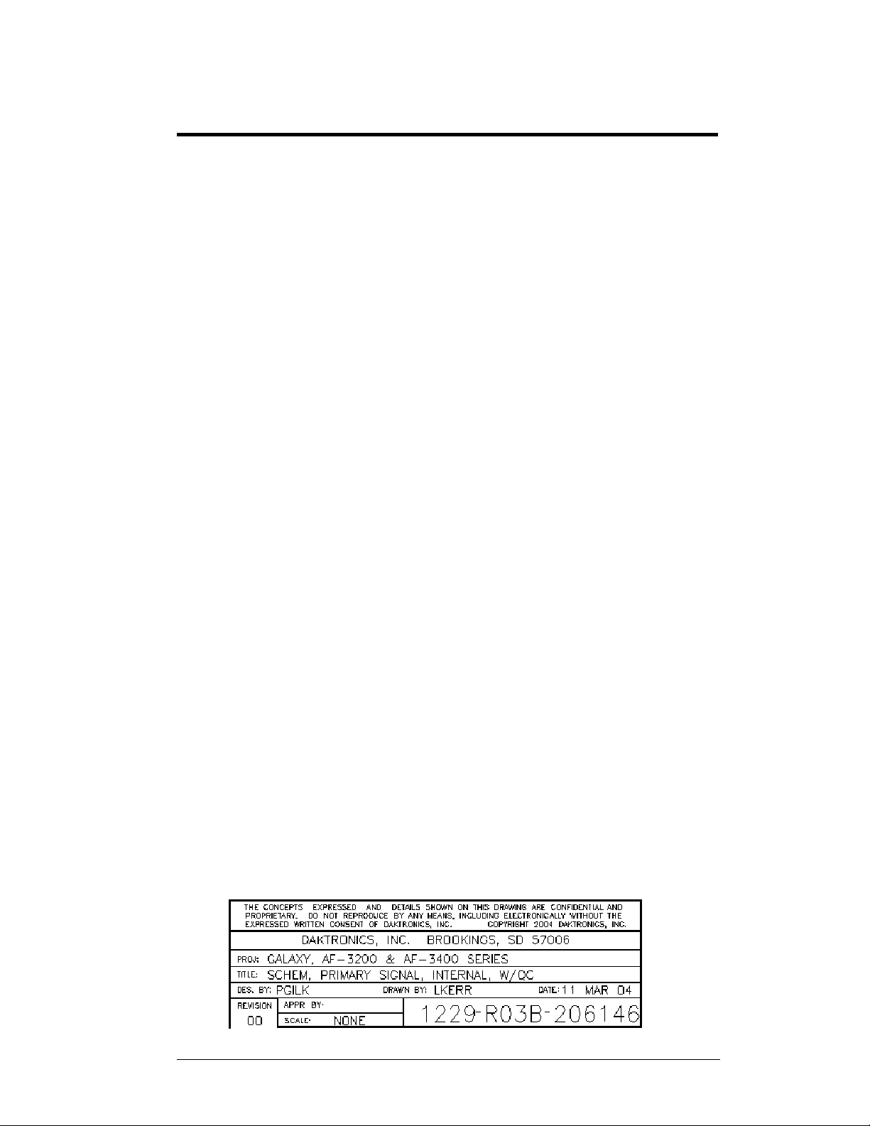
Figure 1 illustrates the Daktronics drawing label. The drawing number is located in the lower-
right corner of the drawing. Listing the last set of digits and the letter preceding them
identifies drawings in the manual. In the example below, the drawing would be referred to as
Drawing B-206146. Reference drawings are inserted after the section that references them.
AE-3010 Indoor Tri-color LED display. For questions regarding the safety,
• Introduction covers the basic information needed to make the most of the rest
of this manual. Take time to read the entire introduction as it defines terms and
explains concepts used throughout the manual.
• Mechanical Installation provides general guidance on sign mounting.
• Electrical Installation gives general guidance on terminating power and signal
cable at the sign.
• Maintenance and Troubleshooting addresses such things as removing basic
sign components, troubleshooting the sign, performing general maintenance,
and exchanging sign components.
• Appendix A includes the drawings referenced in this manual.
• Appendix B contains general information about the signal converters.
• Appendix C provides general information about the optional temperature
sensor.
• Appendix D provides information on the configuration of the serial server.
• System Riser Diagrams: Overall system layout from control computer to sign,
power, and phase requirements.
• Shop Drawings: Fan locations, mounting information, power and signal
entrance points, and access method (front and rear).
• Schematics: Power and signal wiring for various components.
• Component Placement Diagrams: Locations of critical internal sign
components, such as power supply assemblies, controller boards, thermostats,
and light detectors.
Figure 1: Drawing Label
Introduction
1-1
Page 10

All references to drawing numbers, appendices, figures, or other manuals are presented
in bold typeface, as shown below.
“Refer to Drawing B-206146 in Appendix A for the power connection.”
Additionally, drawings referenced in a particular section are listed at the beginning of
that section as seen in the following example:
Reference Drawing:
Schem, Primary Signal, Internal, W/QC ............................ Drawing B-206146
Daktronics signs are built for long life and require little maintenance. However, from
time to time, certain sign components will need replacing. The Replacement Parts List
in Section 4.7 provides the names and part numbers of components that may need to be
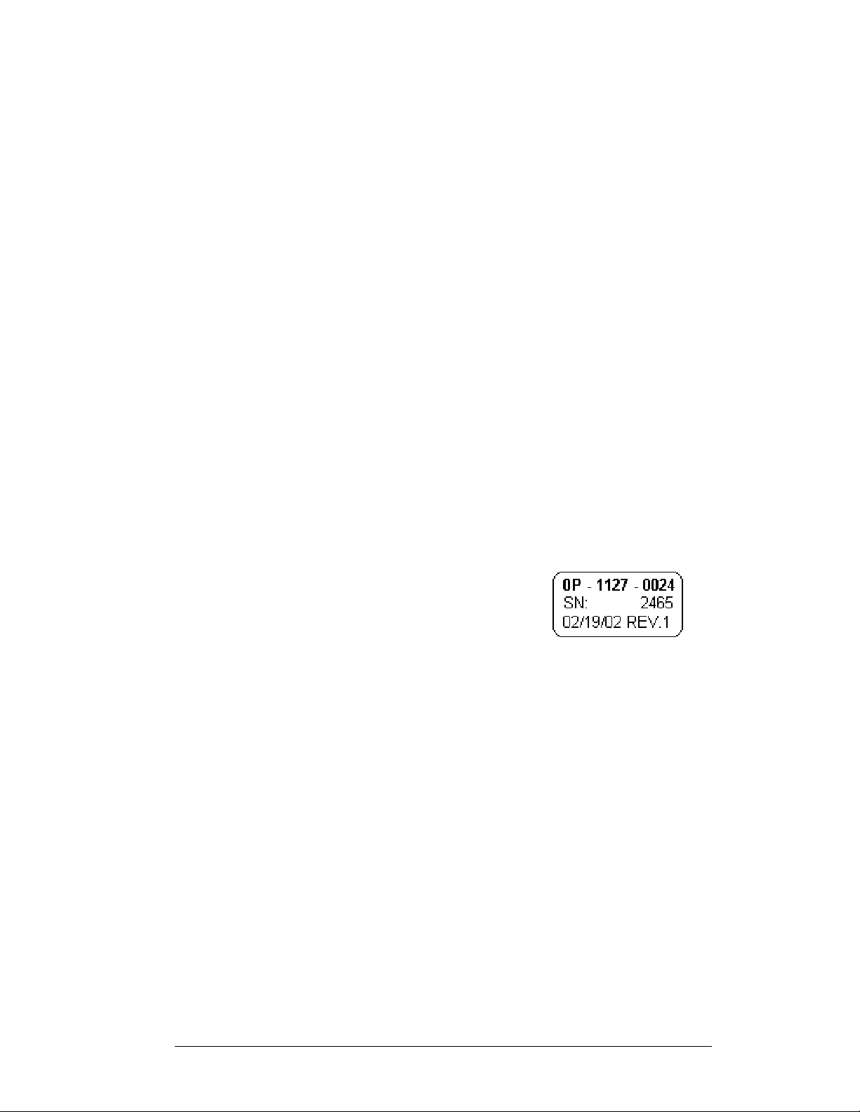
ordered during the life of the sign. Most sign components have a white label that lists the
part number. The component part number is in the following format: 0P-_ _ _ _-_ _ _ _
(component) or 0A-_ _ _ _-_ _ _ _ (multi-component assembly).
Following the Replacement Parts List is the Daktronics Exchange and Return and
Repair Programs in Section 4.8. Refer to these instructions if any sign component
needs replacement or repair.
1.1 Safety Precautions
Important Safeguards:
1. Read and understand these instructions before installing.
2. Be sure the sign is properly grounded.
3. Disconnect power when servicing the sign.
4. Do not modify the sign structure or attach any panels or coverings to the
sign without the written consent of Daktronics, Inc.
5. Most products are equipped with a 3-wire grounding-type plug having a
third (grounding) pin. This plug will only fit into a grounding-type outlet.
This is a safety feature. Do not defeat the purpose of the grounding-type
plug.
1-2
Introduction
Page 11

1.2 Network Concepts
The concept of using LED displays as a cost effective, high impact method of
communication is rapidly growing throughout many industries and businesses. The
reasons for this growth are many, but the need for additional features and the
complexity of multiple sign installations has emerged. Daktronics display systems
are designed to meet those needs. The common thread to most client requests is a
means of programming and controlling a group of signs from a central control point.
Daktronics responded by developing a power system of interconnecting and
controlling signs. Great care has been taken to design products that will satisfy a
wide variety of installations. Some of the design goals of these systems include the
following:
• Easy transfer of messages
• The ability to tell a sign or group of signs in the network which message
should run
• The ability to determine the status of any sign on the network
• The ability to control multiple sign technologies on the same network
In order to avoid technical difficulties, Daktronics uses the popular and readily
available RJ11 connector. This connector is also used on modern home and office
telephone equipment, allowing for easily understood installation procedures.
All that is required for signal installation is standard six (6)-conductor modular
telephone wire and a tool to install the connector. Tools required for mounting the
display depend on the location and size of the display. For some installations, it may
be possible to purchase pre-terminated telephone cables for use with the displays.
There are four (4) network systems available: RS232, RS422, modem and TCP/IP
(Ethernet).
RS232 Network
RS232 (EIA/TIA-232-E) is a standard communication interface that employs a
single-ended serial transmission scheme. The RS232 uses a maximum cable length
of 7.6 meters (approximately 25 feet). This interface was designed for computer
communication at short distances. The computer used will require an RS232 serial
communications port. Refer to Section 3 for additional information.
RS422 Network
RS422 (EIA/TIA-422-B) is a standard communication interface that utilizes a
differential balanced transmission scheme, which uses a typical maximum cable
length of 1.2 km (approximately 4,000 feet). The main advantage of RS422 over
RS232 is the longer cable length. A signal converter is needed to convert the
computer’s RS232 to RS422. Refer to Section 3 for additional information.
Modem Network
The modem is a standard communication interface that utilizes standard phone
transmission lines. The phone company assigns each phone line a number that the
modem uses to communicate between the control computer and display. Refer to
Section 3 for additional information.
Introduction
1-3
Page 12
TCP/IP Network
The TCP/IP protocol is an interface allowing the Ethernet network card (installed in
the operator’s computer) to communicate with the display via a Local Area Network
(LAN). Refer to Section 3 and Appendix D for additional information.
1.3 Display Overview
The Daktronics indoor LED displays have been designed and manufactured for
performance, reliability, easy maintenance, and long life. The displays consist of an
array of LED pixels. The configuration of LED pixels is dependent on the family of
LED displays.
A typical display system consists of a Windows
running Venus
single-face units, which are single-sided stand-alone displays.
®
Venus
2000, or XP Home/Professional operating systems on an IBM
computer. Refer to the Venus
installation and operation of the Venus
Refer to Section 4 for the summaries of how signal and power are routed through
the displays.
Galaxy displays are graphic indoor LED displays, which are available in tri-color
(red, green, and amber) characters. Daktronics offers Galaxy displays with a 7.62
center-to-center spacing, with characters in six (6) different lengths. The Galaxy
model numbers are described as follows: AE-3010-RRxCCC-7.62-TRI.
AE-3010 =
RR =
CCC =
7.62 =
®
1500 software and one or more displays. The displays are offered as
1500 is a software package that runs under Windows® 98, ME™, NT® 4.0,
Indoor Galaxy® Display
Number of rows high (16, 32 and 48 are
available)
Number of Columns Long (96, 128, 160,
192, 224 and 256 are available)
7.62mm center-to-center pixel spacing
®
based personal computer (PC)
®
®
1500 controller operator’s manual (ED-13530) for
®
1500 editing station.
-compatible
TRI =
Tricolor (red, green and amber)
1.4 Component Identification
The following illustrations depict some of the more commonly accessed Galaxy sign
components. Because Daktronics occasionally alters standard design to meet
customer needs, the actual sign design may vary slightly from the illustrations listed.
This is only a brief overview. Refer to Section 4 for more detailed information on
maintaining and troubleshooting various sign components.
Controller: The display’s controller is the “brains” of the display. The controller
receives, translates, and activates the signal information from the control computer
to the appropriate pixels on the sign accordingly.
1-4
Introduction
Page 13
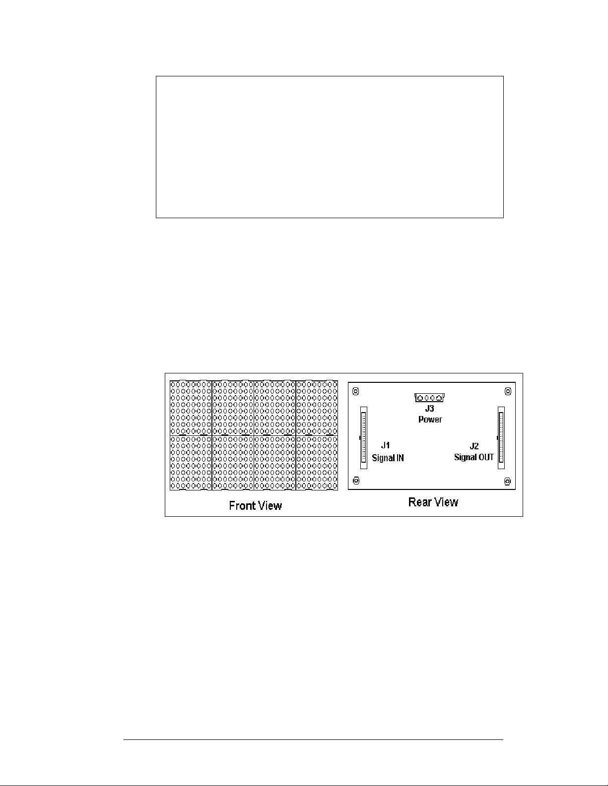
Figure 2: MDC Controller
LED (light emitting diode): Low energy, high intensity lighting units.
Pixel: Each circle on an LED block represents one pixel. Each pixel is made up of a
red and green LED which when both lit creates the amber color. For monochrome
displays, only a red LED is used in each pixel.
Display/Driver Module: The module shown in
Figure 3 is 16 pixels high by 32
pixels wide. Each is individually removable from the front of the sign. The LED
pixel blocks are mounted directly onto the module board. The driver is responsible
for the switching and intensity levels of the LEDs.
Figure 3: 16x32 Pixel Module (Front and Rear View)
Power Supply: Converts AC line voltage from the load center to low DC voltage
for one or more module driver boards.
Galaxy: Daktronics trademarked name for LED monochrome or tri-colored matrix
signs.
Network: Consists of multiple signs connected to each other. Up to 240 Venus 1500
controlled displays can exist on one network.
RS232: Standard PC communication type with a maximum cable length of 25 feet
(7.62 meters).
RS422: Standard differential communication type with a maximum cable length of
4,000 feet (1.2 kilometers). A signal converter is required to convert the comuter’s
RS232 signal to RS422.
Introduction
1-5
Page 14
Serial Port: An actual serial port is required for direct connections from the
computer or those through a signal converter. Certain USB adapters create an
“actual” serial port and others create “virtual” ports. The Venus 1500 software will
not recognize a virtual port; therefore use of a USB adapter is not supported by
Daktronics.
Serial Server: Device used to obtain information from a
LAN and convert it to a serial signal. The communication
protocol used is called TCP/IP.
Sign Address: Identification number assigned to each sign
of a network. Flipping DIP switches on the controller sets the
sign address. The control software uses the address to locate
and communicate with each sign, but signs on the same
network cannot have the same address.
Signal Cable Tester: Used to test the cable connections and
data communications through an RJ11 jack.
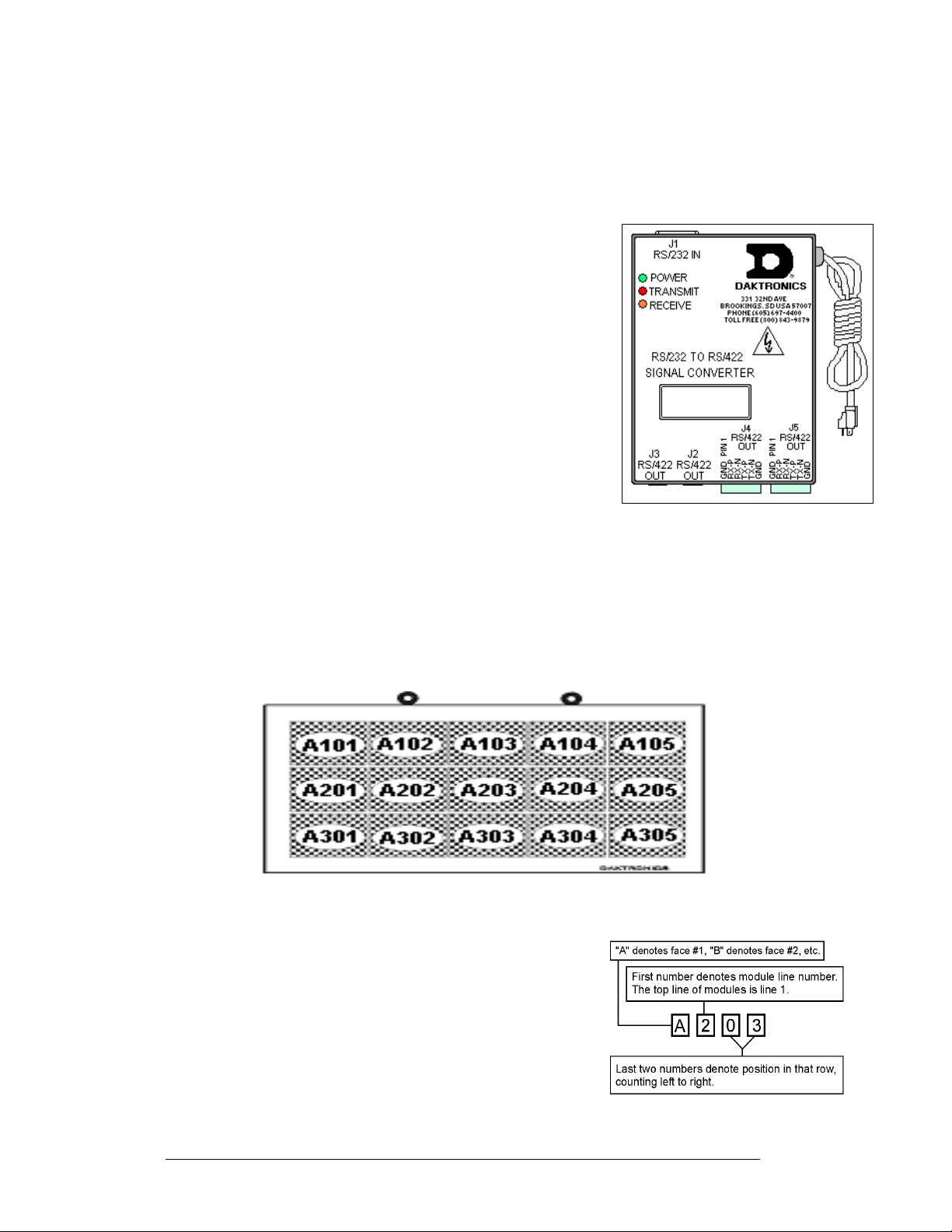
Signal Converter: Daktronics supplied unit that converts the
data from RS232 to RS422, or RS232 to fiber optic signal.
The signal converter is connected to the control PC via a
straight though serial cable. The RS232 to RS422 signal
converter is shown in
Figure 4.
Figure 4: RS232 to RS422 Signal
Converter
1.5 Daktronics Nomenclature
To fully understand some Daktronics drawings, such as schematics, it is necessary to
know how various components are labeled in those drawings. This information is
also useful when trying to communicate maintenance or troubleshooting efforts.
Figure 5: Module Numbering Example – 48x160 Front
A module is the building block of the Galaxy sign. Each
module measures 16 pixels high by 32 pixels wide. By
placing modules side-by-side and on top of one another,
a sign of any size can be designed and built. Ind iv id ual
modules can be easily removed from the sign if
required.
modules on a Galaxy sign.
module numbering method.
Figure 5 illustrates how Daktronics numbers
Figure 6 breaks down the
Figure 6: Module Numbering
1-6
Introduction
Page 15
The label “A” on a drawing typically denotes an assembly. An assembly can be a
single circuit board or a collection of components that function together, usually
mounted on a single plate or in a single enclosure. Assemblies are divided into two
types: those that route signal and those that route power.
In addition, the following labeling formats might be found on various Daktronics
drawings:
• “TB_ _” represents a termination block for power or signal cable.
• “F_ _” stands for a fuse.
• “E_ _” indicates a grounding point.
• “J_ _” symbolizes a power or signal jack.
• “P_ _” identifies a power or signal plug for the opposite jack.
Finally, Daktronics part numbers are commonly found on drawings. Those part
numbers can be used when requesting replacement parts from Daktronics Customer
Service. Take note of the following part number formats:
• “0P-_ _ _ _-_ _ _ _” denotes an individual circuit board, such as a driver
board.
• “0A-_ _ _ _-_ _ _ _” represents an assembly, such as a circuit board and the
plate or bracket to which it is mounted. A collection of circuit boards
working as a single unit may also carry an assembly label.
• “W-_ _ _ _” shows a wire or cable. Cables may also carry the assembly
numbering format in certain circumstances. This is especially true of ribbon
cables.
• “F-_ _ _ _” indicates a fuse.
Most circuit boards and components within this sign
carry a label that lists the part number of the unit. If a
circuit board or assembly is not listed in the
Replacement Parts List in Section 4.7, use the label
to order a replacement. A typical label is shown in
Figure 7. The part number is in bold.
Figure 7: Typical Label
Introduction
1-7
Page 16

Page 17

Section 2: Mechanical Installation
Note: Daktronics does not guarantee the warranty in situations where the sign is not
constantly in a stable environment.
Daktronics engineering staff must approve any changes made to the display. If any
modifications are made, detailed drawings of the changes must be submitted to Daktronics
for evaluation and approval, or the warranty may be void.
Daktronics is not responsible for installation or the structural integrity of support
structures done by others. It is the customer’s responsibility to make sure that a qualified
structural engineer has ensured the structure and any additional hardware.
2.1 Mechanical Installation Overview
Because every installation site is unique, there is no single Daktronics-approved
procedure for mounting the Galaxy signs. The information contained in this section
is general information only and may or may not be appropriate for your particular
installation.
A qualified individual must make all decisions regarding the mounting of this
sign.
Read both the mechanical and electrical installation sections of this manual
before beginning any installation procedures.
2.2 Support Structure Design
Daktronics recommends either a wall mount or a hanging mount method.
Remember to have all mounted displays inspected by a qualified structural engineer.
Daktronics is not responsible for the installation or the structural integrity of
support structures done by others.
2.3 Display Ventilation Requirements
Fresh air inlets and exhaust vents should not be obstructed in any way. To ensure
proper ventilation, use the Daktronics suggested mounting methods. Consult a
Daktronics sales representative for clearance requirements regarding your particular
display if you are using a different mounting method. If ventilation requirements are
not met, the display warranty will be void.
Mechanical Installation 2-1
Page 18
2.4 Hanging Mount
Reference Drawings:
Mounting Methods, AE-3010-*****-7.62mm ................ Drawing A-107655
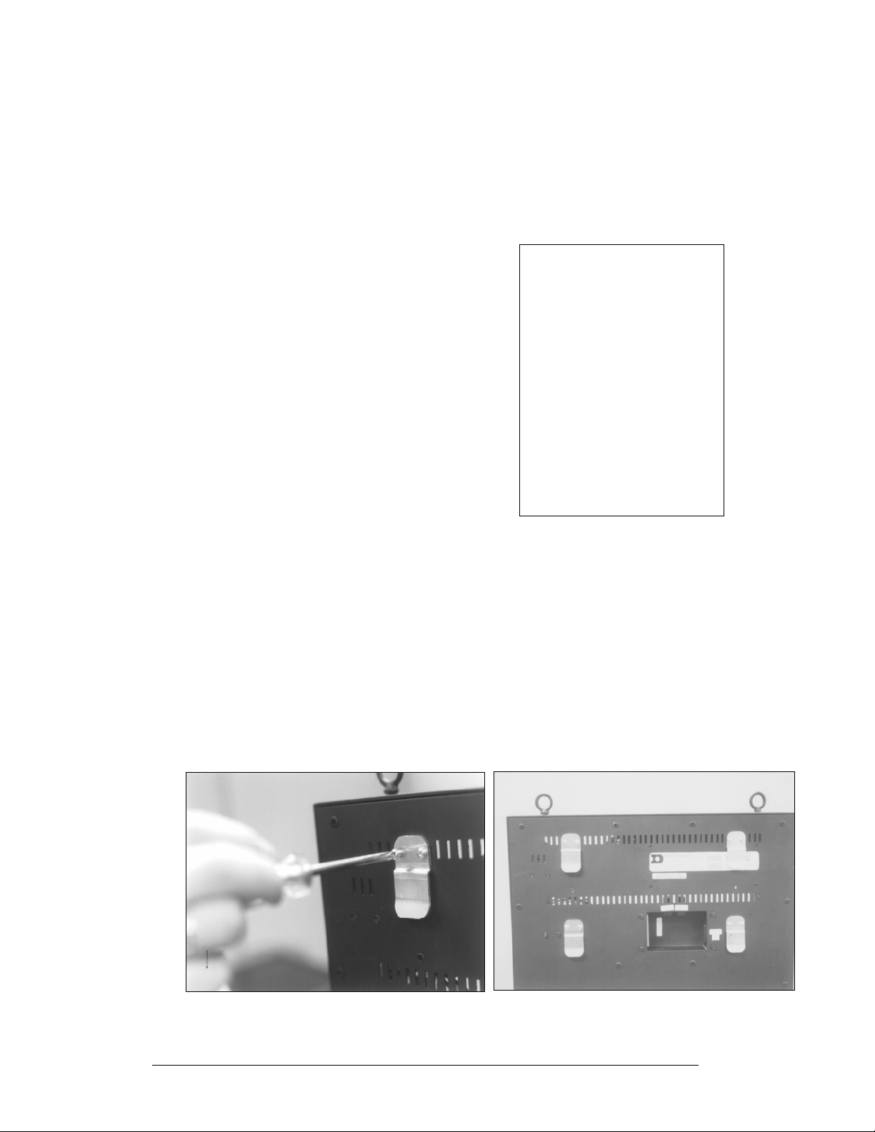
The Galaxy Series Display has two pre-drilled holes in the top of the display for use
in the hanging mount method. Refer to Drawing A-107655 and the directions below
to hang the display.
1. Remove the two retaining screws from the
top of the display using a Philips
screwdriver.
2. Slide the provided sealing washer over the
threads of each eyebolt.
3. Insert the eyebolts in to the pre-drilled
holes on the display (refer to
4. Hand-tighten the eyebolts.
Note: Hanging the display without using the
supplied eyebolts will negate the warranty.
Attaching or hanging anything from the display will
render the warranty null and void.
Figure 8).
2.5 Wall Mount
Reference Drawing:
Shop Drawing, AE-3010-16***-7.62mm-SB-RG .......... Drawing A-107618
Shop Drawing, AE-3010-32***-7.62mm-SB-RG .......... Drawing A-107636
Shop Drawing, AE-3010-48***-7.62mm-SB-RG .......... Drawing A-107639
The Galaxy has holes on the back of the display for the attachment of the wall
mounting clips. Using the #8-32 screws provided with the display, attach the
mounting clips to the rear of the display as shown (refer to both
and the Shop Drawing for your sign size for more information). Use all the supplied
clips.
Figure 8: Eye Bolt Insertion
Figure 10, Figure 9
Figure 10: Wall Mounting Clip Attachment
2-2
Figure 9: Mounting Clip Placement; Rear View
Mechanical Installation
Page 19

1. Mount the wall bracket to the wall where the display is to be located. Refer to the
referenced shop drawings for your display model to determine the location of the
bracket with respect to the display. Be sure the bracket is mounted to sufficiently
support the weight of the display. Have all mountings inspected by a qualified
structural engineer.
2. Set the display on the wall-mounted bracket. The bracket fits onto the wall mounting
clips as shown in the reference drawings.
Mechanical Installation 2-3
Page 20

Page 21
Section 3: Electrical Installation
Only a qualified individual should terminate power and signal cable within this
Daktronics sign.
The Daktronics engineering staff must approve any changes made to the sign. Before altering
the sign, submit detailed drawings for the proposed modifications to the Daktronics
engineering staff for evaluation and approval, or the warranty will be rend ered null and void.
3.1 Common Connectors in the Sign
The power and signal connections in the signs use several different types of
connectors. Take special care when disengaging any connector so as not to damage
the connector, the cable or the circuit board.
When pulling a connector plug from a jack, do not pull on the wire or cable; pull on
the jack itself. Pulling on the wires may damage the cable and connector.
The following information presents some common connectors encountered during
sign installation and maintenance:
1. Ribbon Cable Connectors:
Figure 11 illustrates a typical ribbon cable connector. To
disconnect the ribbon cable, push the plastic clips on the
sides of the jack inward.
Before replacing a ribbon cable connector, spray it with
DeoxIT
may cause signal problems. In addition, apply a generous
amount of CalLube
inserting it into the jack. This paste will protect both the
plug and the jack from corrosion.
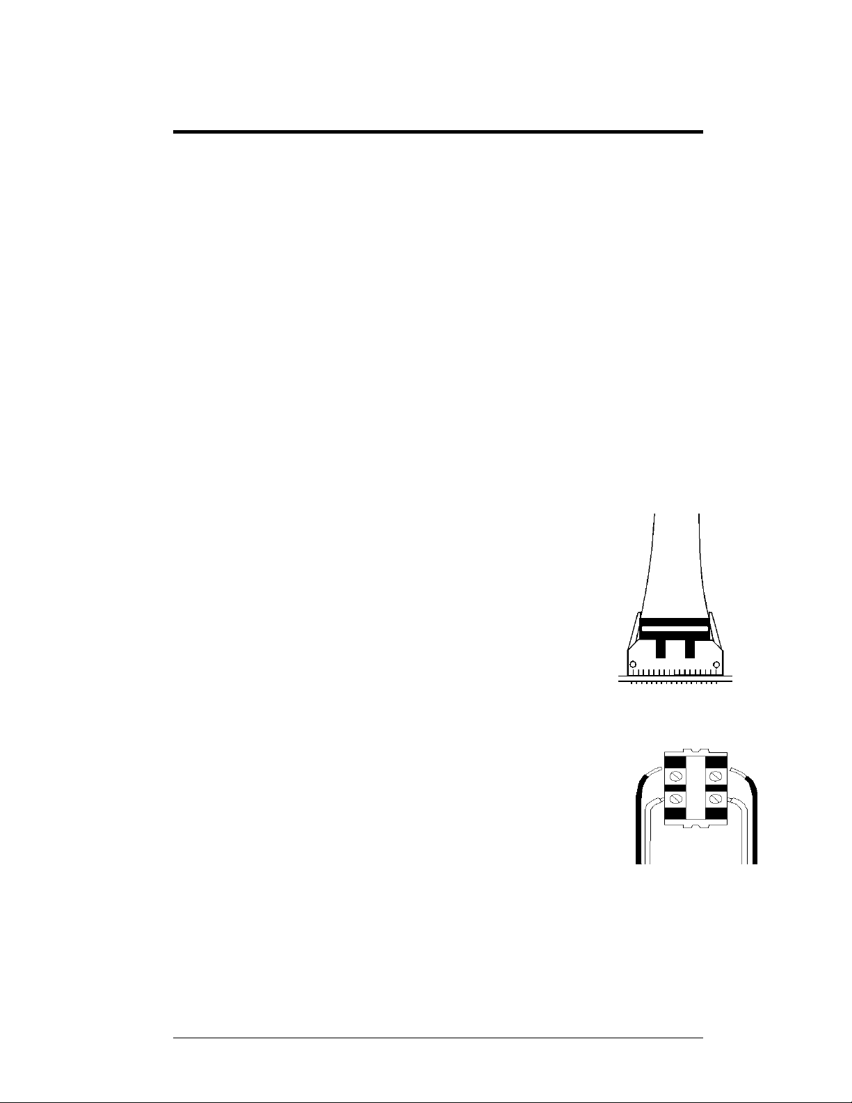
2. Termination Blocks:
Termination blocks are usually used to connect internal
power and signal wires to wires of the same type coming
into the sign from an external source. Power wires need to
have one-half inch of insulation stripped from the end of
the wire prior to termination. Tighten all screws firmly to
ensure a good electrical connection. Refer to
™
contact cleaner to remove any foreign matter that
™
protector paste to the plug before
Figure 12.
Figure 11: Ribbon
Cable Connector
Figure 12: Termination
Block
Electrical Installation 3-1
Page 22
3. Phoenix™-Style Connectors:
Phoenix-style connectors, which are usually green, are used
for the external temperature sensor termination to the
display. Refer to
Figure 13. Strip one-quarter inch of
insulation from the wire prior to termination. To remove a
wire, turn the above screw counter-clockwise to loosen the
connector's grip on the wire. To insert a wire, push the bare
wire into the connector, and turn the above screw clockwise
to lock the wire into place.
4. Mate-n-Lok™ Connectors:
The Mate-n-Lok connectors found in the signs are white and
come in a variety of sizes.
Figure 14 illustrates a four-pin
Mate-n-Lok connector. To remove the plug from the jack,
squeeze the plastic locking clasps on the side of the plug and
pull it from the jack.
5. Phone Jacks (RJ11/RJ45 Connectors):
RJ11 and RJ45 connectors are similar to the telephone and
network connectors found in homes and businesses cables.
In order to remove this plug from the jack, depress the small
clip on the underside of the plug. Before replacing an RJ
connector, spray it with DeoxIT
any foreign matter that may cause signal problems. In
addition, apply a generous amount of CalLube
paste to the plug before inserting it into the jack. This paste
will protect both the plug and the jack from corrosion.
3.2 Control Cable Categories
™
contact cleaner to remove
™
protector
Figure 13: PhoenixStyle
Connector
Figure 14: Mate-nLok Connector
3-2
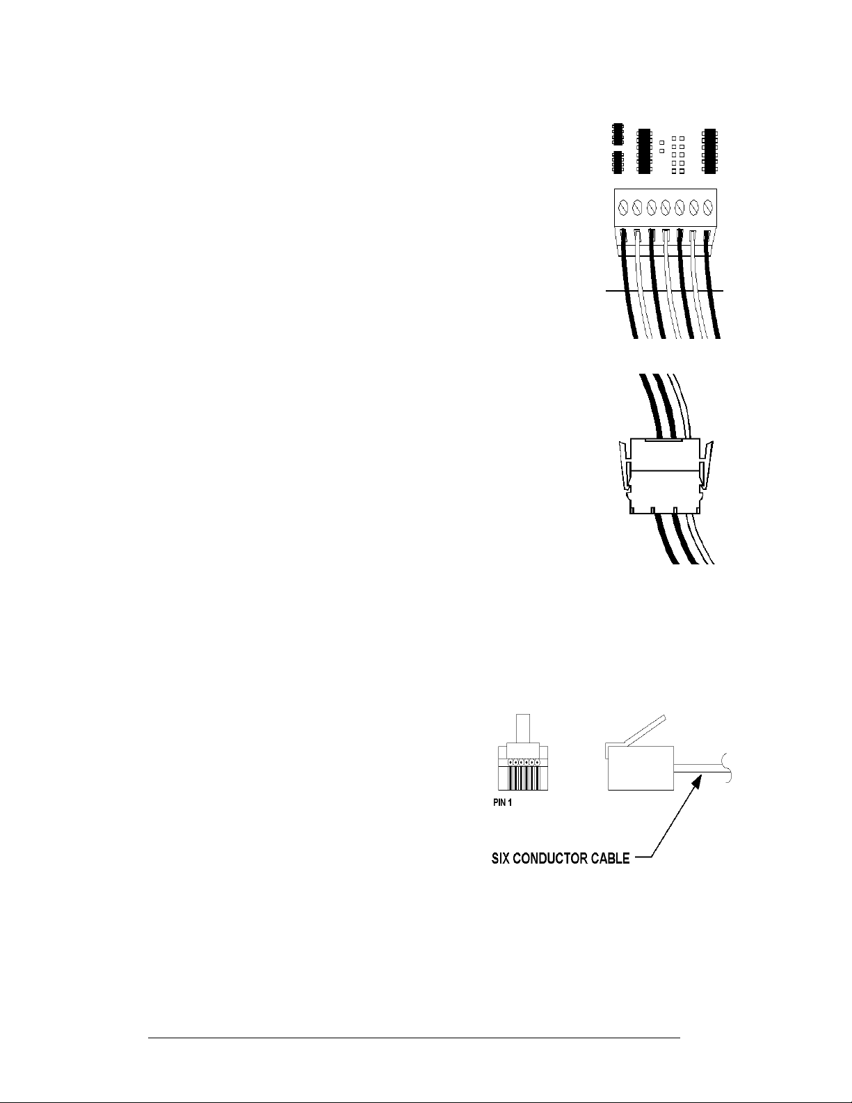
Cable Types
The conductor connector used in the network is an industry standard, 6-pin RJ11.
This connector can be found on many
telephones and LANs.
The cable used in the network is a standard flat
six-conductor telephone cable (standard flipped
cable). Refer to
end that is the mirror image of the other end (i.e.
the cable is flipped). Refer to
standard flipped cable.
Figure 15. This cable has one
Figure 16 for a
Figure 15: 6-Conductor RJ11 Connector and
Cable
Electrical Installation
Page 23
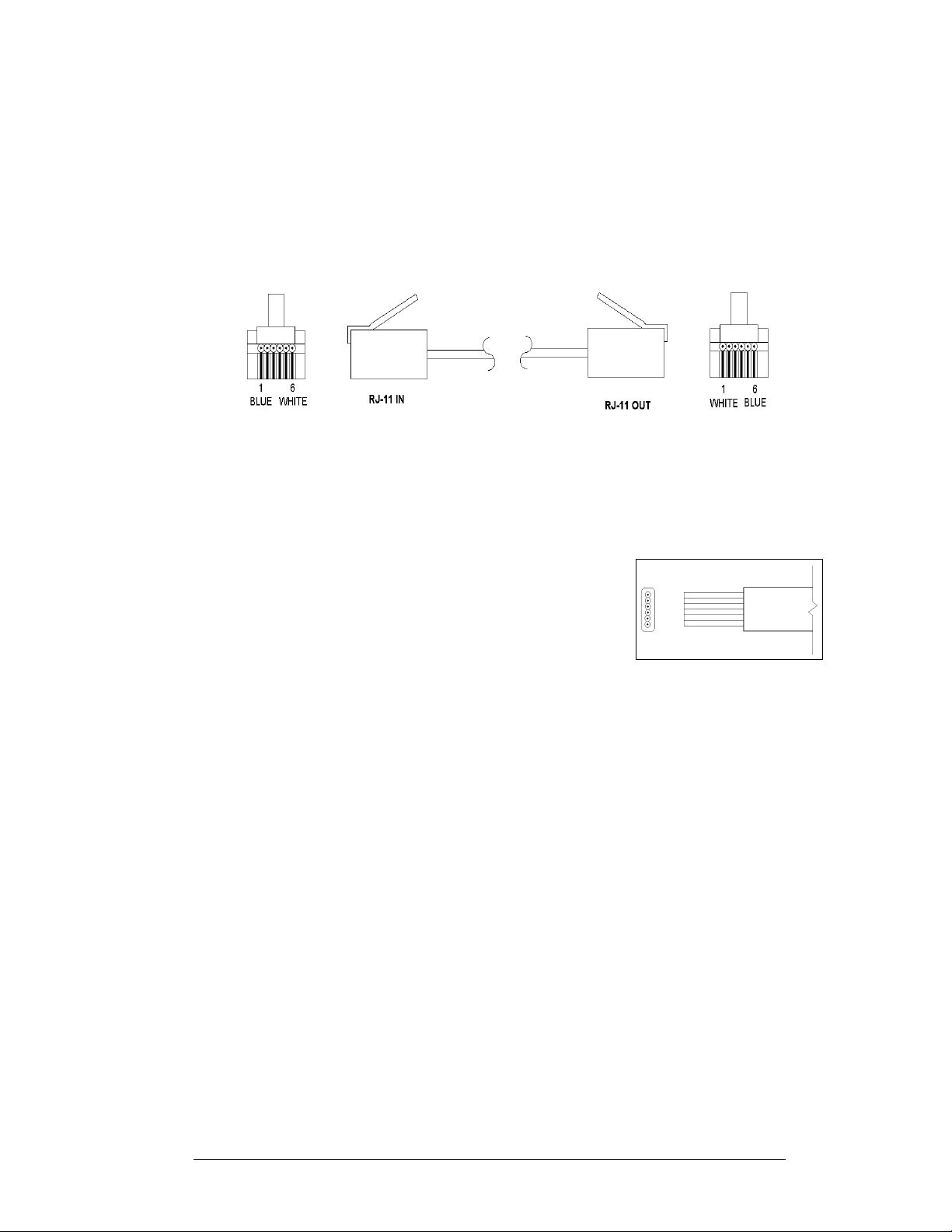
s
Notice in
Figure 16 that the color code on one connector must be made the opposite
on the other connector. When installing a network, it is not easy to remember in
which direction the previous end was oriented. One simple way to avoid confusion is
to standardize the color code, having one color for the connector going into the
output of a sign, and the opposite color for a connector going into the input of a sign.
This will help ensure correct cabling since cables are always installed from the
output jack of one sign to the input jack of the next sign.
Figure 16: Flipped Cable with RJ Connector
Installing an RJ11 Connector
Installing an RJ11 connector on the end of the six-conductor cable is a simple task
when the correct tools are used. The RJ11 crimping tool (Daktronics part number
TH-1033) performs two separate steps.
First, use the crimping tool to strip the outer insulation
from the inner wires. This does not result in bare wires
since only the gray outer jacket is removed. After
correct stripping, the wire will appear as shown in
Figure 17.
Figure 17: Wire with Outer
Jacket Stripped
3.3 Power
Reference Drawings:
Shop Drawing; AE-3010-16***-7.62mm-SBRG ........... Drawing A-107618
Shop Drawing; AE-3010-32***-762mm-SBRG ............ Drawing A-107636
Shop Drawing; AE-3010-48***-762mm-SBRG ............ Drawing A-107639
Refer to the Shop Drawings listed in this section for voltage and current
requirements. A 120VAC single-phase outlet powers the displays.
Do not connect the display to any voltage other than that listed on the Daktronics
product label attached to the back of the display.
The display system must be connected to earth-ground. Proper grounding is
necessary for reliable equipment operation. It also protects the equipment from
damaging electrical disturbances and lightning.
Electrical Installation 3-3
Page 24
3.4 Grounding
Proper grounding is necessary for reliable equipment operation and provides some
protection to the equipment from damaging electrical disturbances. The displays are
supplied with a power cord that contains an earth ground conductor. Make sure to
plug this cord into a grounded outlet. The display must be properly grounded or
the warranty will be void.
Note: Displays must be earth grounded according to local electrical code.
The Galaxy displays are supplied with an eight (8) foot power cord.
The socket-outlet should be installed near the equipment and be easily accessible.
Plug the power cord into the back of the display as shown in
Figure 18.
Figure 18: Power Cord Connection
3.5 Signal Termination from Computer to Display
RS232
Reference Drawings:
V1500 System Riser Diagram; RS/232 ......................... Drawing A-91388
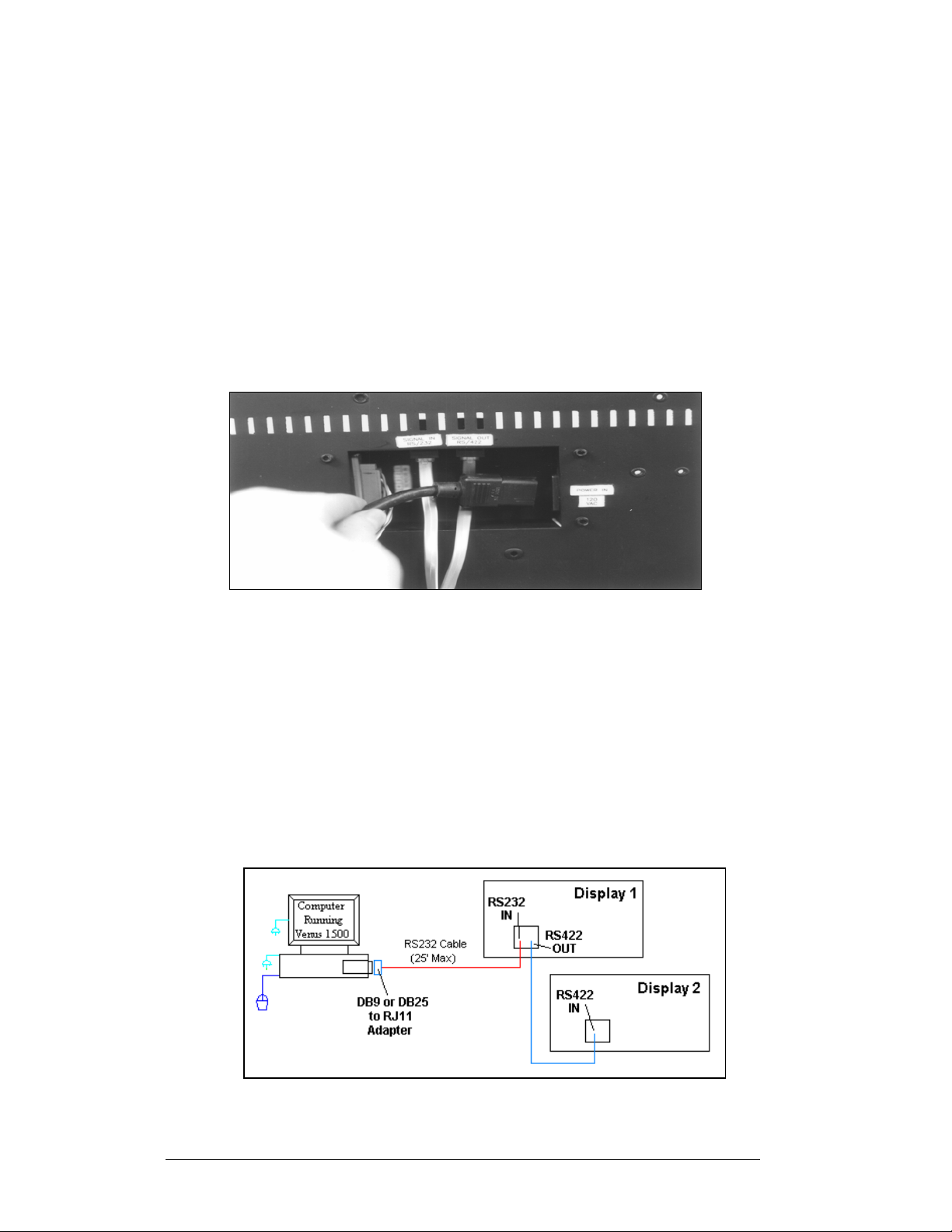
A RS232 system connects the first sign directly to the computer via an adapter. The
adapter has either a DB9 (0A-1115-0042) or a DB25 (0A-1115-0044) connector on
one side, and an RJ11 jack on the other. One end of the RJ11 cable plugs into this
adaptor and the other end to the display. Refer to
for system layout.
Figure 19 and Drawing A-91388
3-4
Figure 19: RS232 System Layout
Electrical Installation
Page 25

Figure 20: RS232 Input Connection
1. Plug the DB9 or DB25 to RJ11 adaptor into the computer’s RS232 serial
port.
2. Plug one end of the flipped RJ11 cable (W-1265) into the adaptor.
3. Plug the opposite end of the cable into the RS232 IN jack on the rear of the
display as shown in
Figure 20.
Pin out of the RS232 IN jack.
Pin Number Function
1 RTS OUT-P
2 RESET OUT-P
3 TX OUT-N
4 GND
5 RX IN-N
6 DCD IN-P
RS422
Reference Drawings:
V1500 System Riser Diagram; RS422 .......................... Drawing A-91387
An RS422 system connects the first sign through a signal converter near the
computer. A serial cable (W-1249) connects to the signal converter, and an RJ11
flipped cable will connect from there to the display. Refer to
Figure 21 and Drawing
Figure 21: RS422 System Layout
A-91387 for system layout.
Electrical Installation 3-5
Page 26

1. Connect the DB9 end of the serial cable to the serial port of the
computer.
2. Connect the DB25 end of the serial cable to J1 on the signal converter
(0A-1127-0237 or 0A-1127-0255).
3. Connect one end of the flipped RJ11 cable to J2 or J3 on the signal
converter as shown in
Figure 22.
Figure 22: RS422 Signal Converter
Connections
Signal Converter to Display Connection Using
Flipped Cable
Signal Converter (J2/J3)
RS422 IN Jack on the
RS422 OUT
Pin 1 (GND) Pin 1 (N.C.)
Pin 2 (TX-N) Pin 2 (D1OUT-P)
Pin 3 (TX-P) Pin 3 (D1OUT-N)
Pin 4 (RX-N) Pin 4 (D1IN-P)
Pin 5 (RX-P) Pin 5 (D1IN-N)
Pin 6 (GND) Pin 6 (N.C.)
Note: The table of the pine outs of the signal converter and the RS422 In at the
display illustrate that the pinouts to both are the same. Therefore, a flipped cable is
required to connect from the signal converter to the display.
Display
3-6
Electrical Installation
Page 27

Modem
Reference Drawings:
V1500 System Riser Diagram, Modem ......................... Drawing A-91386
A modem system uses standard phone lines to connect from the computer to the
display. Both the modem at the computer and at the display will need to be
connected to a phone jack. Refer to Drawing A-91386 and
layout.
Figure 23 for the system
Figure 23: Modem System Layout
1. Modem connection:
a. If using an internal modem, connect a phone line from the
modem to the wall phone jack.
b. If using an external modem, connect the cable from the serial
port on the computer to the input on the modem, then connect a
phone line from the modem to the wall jack. Plug in the power
pack to the external modem.
2. Connect an RJ11 phone line from the wall jack to the input on the back
of the display.
3. The display requires a dedicated phone line.
Pin out of the Modem In Jack
Pin Number Function
Pin 1 N.C.
Pin 2 N.C.
Pin 3 TIP-P
Pin 4 Ring-P
Pin 5 N.C.
Pin 6 N.C.
TCP/IP or LAN System
Reference Drawings:
System Riser Diagram, TCP/IP Network ........................... Drawing A-231373
To communicate to the display over an Ethernet network requires an Ethernet card in
the computer and a network connection to the display. Refer to Drawing A-231373
Figure 24 for system layout.
and
Electrical Installation 3-7
Page 28

Figure 24: TCP/IP (Ethernet) System Layout
1. Connect the second network cable from a network jack to the display.
2. The maximum distance from the network hub or switch is 100m.
Note: The Serial Server used in each case is the same, but it must be programmed
for either RS232 or RS422 output.
3.6 Signal Connection Between Two (or More) Displays
Reference Drawings:
System Riser Diagram, Modem .................................... Drawing A-91386
System Riser Diagram; RS422 ..................................... Drawing A-91387
System Riser Diagram, RS232 ..................................... Drawing A-91388
System Riser Diagram, TCP/IP Network .................... Drawing A-231373
The signal connection between displays is
the same for all types of systems. Refer to
the System Riser Diagram for your
system for the connection method.
When wiring from display to display the
RJ11 cable between displays will always
be flipped. See Section 3.2 for
descriptions and methods for making
flipped cables. The best method of wiring
the displays together is to start at the first
sign, and connect from the out of that
display to the in port on the next display,
etc. in the network.
RS422 Out Jack on Display
Pin 1 Gnd-N
Pin 2 D2Out-N
Pin 3 D2Out-P
Pin 4 D2In-N
Pin 5 D2In-P
Pin 6 Gnd-N
Figure 25: RS422 Interconnection
RS422 IN Jack on Display
Pin 1 N.C.
Pin 2 D1Out-P
Pin 3 D1Out-N
Pin 4 D1In-P
Pin 5 D1Out-N
Pin 6 N.C.
3-8
Electrical Installation
Page 29

1. Plug one end of the flipped RJ11 cable into the “Signal Out” output jack on the
first display and the other end of the cable in the input jack on the next display.
2. Refer to
3. Continue this procedure throughout the network. When the cabling is
complete, the last display will have nothing in the output jack.
Figure 25.
3.7 Initial Operation
Each time power is applied to the display; the display will run through an
initialization in which it will display the following:
1. Output Test (DDDs)
2. Product Name (Galaxy)
3. Display Size (Row x Column)
4. Firmware Number (ED10134)
5. Firmware Revision (Rev X.XX)
6. COM1 Configuration (C1: V15/RTD)
7. COM2 Configuration (C2: None)
8. Line Frequency (60 Hz)
9. Hardware Address (HW: XX)
10. Software Address (SW: XX)
11. Display Name
12. Modem (if Present)
Electrical Installation 3-9
Page 30

Page 31

Section 4: Maintenance and
Troubleshooting
Important Notes:
1. Disconnect power before any repair or maintenance
work is done on the display.
2. Qualified service personnel must make any access to
internal display electronics.
3. Care must be taken when handling the display’s face
panel to prevent scratches or other damage.
4.1 Maintenance and Troubleshooting Overview
Daktronics Galaxy® series AE-3010 displays are front accessible; meaning access to
the internal components can be gained only from the front of the display.
This section provides the following Galaxy
• Signal Routing Summaries provide a basic explanation of the way signal
travels through the display.
• Power Routing Summaries offer a basic explanation of the way power
travels through the display.
• Service and Diagnostics give instructions for removing various display
components, and explains the functions of circuit board connectors and the
meanings of any diagnostic LEDs.
• Maintenance includes a number of steps to take to keep this Galaxy
display in a safe, working order.
• Troubleshooting lists some possible display malfunctions, and provides a
number of possible causes for that malfunction.
• Replacement Parts List includes the description and part number of
display components that may need replacing during the life of this display.
• Exchange and Repair and Return Programs explain Daktronics
component return policy.
4.2 Signal Summary
The signal routing for the display, as shown in Figure 26, can be summarized as
follows:
1. Data from the control computer, which runs Venus
via RS232, RS422, modem, or Ethernet signal to the first display.
2. The input signal to the display is connected to the display controller. From
the controller, the signal then travels over one or more 40-conductor ribbon
cables (J1 through J3 provide signal out) to J2 on the driver of the first row
of modules in the display.
3. Data exits at J1 and is relayed to J2 of the next module and so on, traveling
down the entire row of modules. The modules use this display data to
control the LEDs.
4. For multiple displays or a display network, an RS422 RJ11 cable relays
signal between the first display and the second display.
Maintenance and Troubleshooting
®
display information:
®
1500 software, travels
®
4-1
Page 32

Figure 26: Signal Summary using RS422
4.3 Power Summary
Reference Drawing:
Schematic; AE-3010-32**(*)-2.1 .................................. Drawing B-102485
Schematic; AE-3010-48**(*)-2.1 .................................. Drawing B-102706
Schematic; AE-3010-16**(*)-2.1 .................................. Drawing B-105418
The power routing for the display can be summarized as follows:
1. Power terminates to the display using a 120 VAC power cord that plugs
into the recessed panel on the back of the display.
2. Incoming power goes through an electrical line filter and a fuse. It is then
distributed to the transformer and the power supplies mounted to the back
sheet of the display.
3. The controller board receives about 10 VAC from the transformer.
4. The power supplies are set to 5.3 VDC. For assistance with the wiring to
the power supplies see the Schematics. Power supplies are preset. Contact
Daktronics Customer Service for the proper settings.
4.4 Service and Diagnostics
4-2
The following sub-sections address servicing of the following display components:
• accessing the interior of the display
• LED module replacement
• power supply replacement
• controller replacement
• display addressing
Maintenance and Troubleshooting
Page 33

Accessing the Interior of the Display
Remove the socket head screws from the face panel using a
9/64” Allen wrench (refer to
Gently pull the face panel from the body of the sign. The
display opens as shown in
panels can now be seen.
To access the display’s interior electronic components:
1. Disconnect Power to the display.
2. Open the face panel as described above.
3. Using a #2 Philips screwdriver, turn the screws
securing the top of the LED module panel to the
cabinet one-quarter turn counter-clockwise. (The
screws are designed to remain in the LED module
flanges, but release from the cabinet.
4. Gently tilt the LED module panel downward from
the body of the display. The panel will be
supported in a horizontal position by lanyards. DO
NOT use the module panel to support additional weight. Refer to
29.
Once the LED module panel is
opened, the display interior will
be visible. Various internal
components, including the
display controller, transformer,
light detector, LED modules,
and power supplies are now
accessible for repair or
replacement.
Figure 27).
Figure 28. The LED module
Figure 27: Removing the Screws
from the Face Panel
Figure
Maintenance and Troubleshooting
Figure 28: Display, Face Panel partially removed
Figure 29: Display Interior
4-3
Page 34

LED Module Replacement
If any LED modules fail, the recommended procedure is to replace the failed module
or send it to Daktronics or a Daktronics Sales and Service office for repair.
To remove an individual module:
1. Disconnect Power to the display.
2. Push the clips outward and gently pull the 40-pin ribbon cables from
the failed module as shown in
3. Open the display and access the display interior as previously
described.
4. Press the tabs on either side of the four-pin power connector to release
it and shown in
Figure 30.
5. Each module is held in place by #6 screws. Using a 3/16” nutdriver,
remove the module screws from the rear of the panel.
6. Gently pull the failed module from the panel. Reverse the previous
Figure 31.
Figure 30: Disconnecting Power from LED
Module
Figure 31: LED Module Ribbon Cable
Removal
steps to attach a new module.
Power Supply Replacement
Note: Disconnect power from the display before removing a power supply.
Power to the LED modules is provided by
a small 5V power supply. Each power
supply can support up to three (3)
modules. They are located on the back
sheet of the display.
Each power supply is secured to a power
supply plate by two (2) 3x10 metric
screws. The plate is secured to the back
sheet by two (2) #6 hex head screws as
shown in
to remove the #6 screws.
Figure 32. Use a 3/16 nutdriver
Figure 32: Loosening Power Supply Screws
4-4
Maintenance and Troubleshooting
Page 35

1. Lift the power supply and plate off the back
sheet standoffs. The metric screws securing
the power supply to the plate are now
accessible.
2. Use a #1 Philips head screwdriver to
remove the screws and free the power
supply.
3. Disconnect the power cables as shown in
Figure 33.
4. The power supply is now fully released and
ready for replacement.
5. Follow the previous steps in reverse order to
reattach the new power supply.
6. Be sure to connect the power wires in the
correct locations
Refer to your display’s Schematic for the proper
wiring configuration.
Figure 33: Power Supply Cable Connections
Accessing and Replacing the Controller Board
The display controller is mounted to the back sheet of the cabinet in the lower left corner.
The controller receives, interprets, and activates the information from the computer to the
appropriate LEDs on the display.
The controller board includes three LEDs:
1. DS1 should be on whenever power is applied to the board.
2. DS2 should have a steady flash to indicate that the controller is running properly.
The normal rate is about once per second. The run LED will flash faster when the
controller is in test mode.
3. DS3 should flash when receiving information from the light sensor.
4. See
Figure 34 below for LED and connector locations.
Figure 34: Controller Board
Maintenance and Troubleshooting
4-5
Page 36

To replace a failed controller:
1. Disconnect power to the display.
2. Open the display and lift the LED module panel to access the interior
components.
3. Label all the signal cables before removing them from the controller
4. Remove all power and signal connections from the board. Pressing outward
on the tabs, and carefully pulling them from the jack releases the “Locked”
connectors.
5. Remove the #6 mounting screws. Five of the five screws are hex head,
while one is a Philips head. Remove the mounting six screws using a 3/16"
nutdriver.
6. Take note of the switch configuration and set the same address on the new
controller.
7. Carefully remove the controller board from the display.
8. Attached the new controller using the #6 screws. Be sure to replace the
Philips head screw in the location where it was removed.
9. Reconnect the power and signal cables.
Display Addressing
Before a display can be run in a sign network, it must have an
address. The display address can be set using “DIP” switches
located on a PC board known as the MDC. The MDC is the circuit
card mounted on the left end of the controller board.
Locate the DIP switches on the MDC. They should be on the
bottom end of the card. Refer to
switches.
When replacing a controller board, be sure to set the DIP switches
to the same address configuration as the defective controller. The
DIP switches follow standard binary code.
Note: By setting the DIP switches to address 0 (flip all the switches
up or toward the numbers on the circuit board), a test mode can be
activated. The display’s power must be turn off and then back on to
recognize test mode, or any address change.
Switch 8 Switch 7 Switch 6 Switch 5 Switch 4 Switch 3 Switch 2 Switch 1 Address
Off Off Off Off Off Off Off Off Test Mode
Off Off Off Off Off Off Off On 1
Off Off Off Off Off Off On Off 2
Off Off Off Off Off Off On On 3
Off Off Off Off Off On Off Off 4
Off Off Off Off Off On Off On 5
Off Off Off Off Off On On Off 6
Off Off Off Off Off On On On 7
Off Off Off Off On Off Off Off 8
Off Off Off Off On Off Off On 9
Off Off Off Off On Off On Off 10
… … … … … … … …
Off On On On On On On On 127
Figure 35 for a picture of the DIP
Figure 35: DIP Switches
(Address 1 shown)
4-6
Maintenance and Troubleshooting
Page 37

4.5 Troubleshooting
This section lists some symptoms that may be encountered with the display. Possible
cause and corrective actions are given. This list does not include every possible
problem, but does represent some of the more common situations that may occur.
Contact Daktronics Customer Service if problems continue with the display (refer to
Section 4.8).
Symptom/Condition Possible Corrective Action
One or more individual LED pixels
will not light.
A column of LED pixels will not light. • Check/Replace ribbon cable.
A row of pixels will not light. • Check/Replace ribbon cable.
A section of the display is not
working. Section extends all the way
to the right side of the display.
Entire display is garbled. • Power down and power back up to
A single line is distorted. • Check/Replace ribbon cable.
Modules, which share power
supplies will not light.
Entire display does not work. • Check 120 VAC power to the display.
Cannot communicate to the display • Check flipped RJ11 cable connections
Controller not operating properly. • Check 10 VAC to the controller board.
• Check/Replace ribbon cable.
• Replace module.
• Check for bent pins on LED blocks
• Replace module.
• Check for bent pins on LED blocks
• Replace module
• Check/ Replace the ribbon cable.
• Check for power on modules.
• Move/Replace the first module on the
left side of the module that is not
working.
• Move/Replace the second module that
isn’t working.
• Replace controller.
watch bootup sequence.
• Check power to controller board.
• Replace the controller board.
• Check for bent pins on module jacks
• Replace the first module on the left side
of the display of the bad line.
• Replace the controller board.
• Check power to modules.
• Check wires and plugs to modules.
• Check AC power to power supplies
• Replace the power supply.
• Check fuse in Power term panel.
• Power down and power up to see
bootup sequence.
• Check 10 VAC to the controller board.
• Check for correct use of software.
to the display.
• Check for use of correct signal input
• Check display configuration.
• Check Venus 1500 software
configuration.
• Check signal converter, modem, or
serial server connections.
• Refer to the Venus 1500 operator’s
manual (ED-13530).
Maintenance and Troubleshooting
4-7
Page 38

Cannot communicate to section of
the network of displays
Display is stuck on bright or dim. • Check Manual/Auto dimming in Venus
• Check the cabling between displays.
• Check for bad input on first bad display.
• Check for bad output on the last good
display.
• Switch the suspected bad display with
a known good display.
• Check displays and software for correct
addressing
1500 software.
• Check light detector cable.
• Replace light detector.
• Replace controller board.
4.6 Initial Operation Information
Each time the display is powered up, the display will run through an initialization in
which it will display the following:
1. Output Test (DDD’s)
2. Product Name (Galaxy)
3. Display Size (Row x Column)
4. Firmware Number (ED10134)
5. Firmware Revision (Rev X.XX)
6. COM1 Configuration (C1: V15/RTD)
7. COM2 Configuration (C2: None)
8. Line Frequency (60 Hz)
9. Hardware Address (HW: XX)
10. Software Address (SW: XX)
11. Display Name
12. If Modem is Present (Modem)
4-8
Maintenance and Troubleshooting
Page 39

4.7 Replacement Parts
Part Description Daktronics
Controller Board, (RS232, Modem) 0A-1161-0179
Controller Board, (RS422) 0A-1161-0180
Controller Board (Ethernet In, RS422 Out) 0A-1161-0258
LED Module; Tri-color 0P-1127-0026
Light Detector 0P-1151-0002
Signal Converter (RS232 to RS422) 0A-1127-0237 or
Modem; RS232 coated 0P-1146-0003
Power Supply; 120VAC input A-1499
Power Supply; 240VAC input A-1449
Transformer (120 VAC Input) T-1072
Transformer (240 VAC Input) T-1106
Buzzer; Solid State, 2-35 VDC 3500 DS-1357
Ribbon Cable; Controller to first mod., 40-pos., 18” W-1362
Ribbon Cable; Between Modules, 40-pos., 8:” W-1341
Serial Cable; RS232, DB9F to DB25M, 6’ W-1249
Adapter; DB9M to DB25F A-1603
PC Adapter; DB9 to RJ11 0A-1115-0042
PC Adapter; DB25 to RJ11 0A-1115-0044
Serial Server (RS232 mode) 0A-1146-0063
Adapter; DB25M to RJ11F (RS232 Serial Server) 0A-1115-0045
Serial Server (RS422 mode) 0A-1146-0064
Adapter; DB25M to RJ11F (RS422 Serial Server) 0A-1146-0062
Cable, RJ45, 10 ft., 4-pair, twisted/Black W-1383
25’ RJ11, 6-cond. cable W-1265
100’ RJ11, 6-cond. cable 0A-1146-0002
500’ RJ11, 6-cond. cable 0A-1146-0003
1000’ RJ11, 6-cond. cable 0A-1146-0004
Cable; 18” RJ11; 6-cond., Straight 0A-1137-0160
Cable; 22 AWG, 4-cond. shielded (temp sensor) W-1234
Power Cord, 360 degree rotating, 8 ft. W-1181
Fuse; MDL-7 (F41, 120 VAC) F-1031
Fuse; MDL-4 (F41, 240 VAC) F-1043
Optional temperature sensor board 0P-1151-0003
Plug, 6-pin male, telephone, 6 pos. P-1211
Crimp Tool for RJ11 connectors TH-1033
Network Cable Tester 0A-1146-0005
Manual; Venus 1500 Operator’s, Version 3
Part No.
0A-1127-0255
ED-13530
Maintenance and Troubleshooting
4-9
Page 40

4.8 Daktronics Exchange and Repair and Return Programs
To serve customers’ repair and maintenance needs, Daktronics offers both an
exchange and a repair and return program. The exchange program reduces down
time by providing timely replacement of key components. This service is provided to
qualified customers who follow the program guidelines explained below. It is our
pleasure to provide this service to ensure you get the most from your Daktronics
products. Please call our Help Desk (1-877-605-1113) if you have any questions
regarding the exchange program or any other Daktronics service.
When you call the Daktronics Help Desk, a trained service technician will work with
you to solve the equipment problem. You will work together to diagnose the
problem and determine which exchange replacement part to ship. If, after you make
the exchange, the equipment still causes problems, please contact our Help Desk
immediately.
If the replacement part fixes the problem, package the defective part in the same
packaging the replacement part arrived in, fill out and attach the enclosed UPS
shipping document, and return the part to Daktronics. You may use the same box
and packing the exchange part was sent in. This will speed up the transaction and
alleviate confusion when the failed component arrives at Daktronics. Daktronics
expects immediate return of the exchange part if it does not solve the problem. For
most equipment, you will be invoiced for the replacement part at the time it is
shipped. This invoice is due when you receive it.
Daktronics reserves the right to refuse equipment that has been damaged due to acts
of nature or causes other than normal wear and tear.
If the defective equipment is not shipped to Daktronics within 30 working days from
the invoice date, it is assumed you are purchasing the replacement part and you will
be invoiced for it. This second invoice represents the difference between the
exchange price and the purchase price of the equipment. This amount is due when
you receive the second invoice. If you return the exchange equipment after 30
working days from invoice date, you will be credited for the amount on the second
invoice minus a restocking fee.
To avoid a restocking charge, please return the defective equipment within 30
days from the invoice date.
Daktronics also offers a Repair and Return program for items not subject to
exchange.
Where to Send: To return parts for service, contact your local representative prior
to shipment to acquire a Return Material Authorization Number (RMA#). If you
have no local representative, call the Daktronics Help Desk for the RMA#. This will
expedite the receiving process.
Packaging for Return: Package and pad the item well to prevent damage during
shipment. Electronic components, such as printed circuit boards, should either be
installed in an enclosure or should be put in an anti-static bag before boxing. Please
enclose your name, address, phone number, and a clear description of symptoms.
4-10
Maintenance and Troubleshooting
Page 41

This is how to reach us:
Mail: Daktronics, Inc., Customer Service
PO Box 5128
331 32nd Avenue
Brookings, SD 57006
Phone: Daktronics Help Desk: 1-877 / 605-1113 (toll free)
or 1-605 / 697-4034
Customer Service Fax: 1-605 / 697-4444
E-mail: helpdesk@daktronics.com
4.9 Daktronics Warranty and Limitation of Liability
The Daktronics Warranty and Limitation of Liability is located in Append ix X. The
Warranty is independent of Extended Service Agreements and is the authority in
matters of service, repair, and display operation.
Maintenance and Troubleshooting
4-11
Page 42

Page 43

Appendix A: Reference Drawings
Drawings listed below are listed according to drawing type, and then listed according to sign
size.
System Riser Diagram, Modem ........................................................ Drawing A-91386
System Riser Diagram, RS422 ......................................................... Drawing A-91387
System Riser Diagram, RS232 ......................................................... Drawing A-91388
Shop Drawing, AE-3010-16***-7.62mm-SB-RG ............................. Drawing A-107618
Shop Drawing, AE-3010-32***-7.62mm-SB-RG ............................. Drawing A-107636
Shop Drawing, AE-3010-48***-7.62mm-SB-RG ............................. Drawing A-107639
Mounting Methods, AE-3010-*****-7.62mm .................................... Drawing A-107655
System Riser Diagram, TCP/IP Network......................................... Drawing A-231373
Schematic; AE-3010-32**(*)-2.1 ...................................................... Drawing B-102485
Schematic; AE-3010-48**(*)-2.1 ...................................................... Drawing B-102706
Schematic; AE-3010-16**(*)-2.1 ...................................................... Drawing B-105418
A-1 Appendix A: Reference Drawings
Page 44

Page 45

Page 46

Page 47

Page 48

Page 49

Page 50

Page 51

Page 52

Page 53

Page 54

Page 55

Page 56

Appendix B: Signal Converter
Appendix B: Signal Converter
B-1
Page 57

Daktronics RS 232-422
Signal Converter
Installation and Testing Manual
ED-14413 Rev 2 18 March 2005
331 32nd Ave PO Box 5128 Brookings SD 57006
Tel 605-697-4034 or 877-605-1113 Fax 605-697-4444
www.daktronics.com e-mail: helpdesk@daktronics.com
1
Page 58

Product 1146
Rev 2 – 17 March 2005
ED14413
DAKTRONICS, INC.
Copyright © 2005
All rights reserved. While every precaution has been taken in the preparation of this manual,
the publisher assumes no responsibility for errors or omissions. No part of this book covered
by the copyrights hereon may be reproduced or copied in any form or by any means – graphic,
electronic, or mechanical, including photocopying, taping, or information storage and retrieval
systems – without written permission of the publisher.
All trademarks are the property of their respective companies
Page 59

Table Of Contents
Section 1: Signal Converters and Loop-back Testing for Direct
Connections........................................................................1-1
1.1 RS422 Loop-Back Test (Outdoor Displays)..................................1-3
1.2 RS422 Loop-Back Test (Indoor/Outdoor Displays)......................1-4
1.3 Loop-Back test with Fiber ............................................................. 1-5
1.4 Conducting the Venus 1500 Software Test ................................... 1-6
Section 2: Electrical and Signal...........................................................2-1
2.1 Electrical Ratings........................................................................... 2-1
2.2 Power Disconnect .......................................................................... 2-1
2.3 Parts Listing................................................................................... 2-1
Section 3: Mounting Instructions........................................................3-1
Section 4: Enviromental Ratings.........................................................4-1
Table Of Contents
i
Page 60

Page 61

Section 1: Signal Converters and Loopback Testing for Direct Connections
The following table gives the typical state of the signal converter when the LEDs are either on
or off. Refer to
locations of the various components.
LED
Indicators
Power
TX
RX
TX/RX
Figure 1 and Figure 2 for an illustration of the signal converters and the
Typical States Troubleshooting
ON
OFF
On Steady
OFF Steady
Brief Flicker SC is transmitting data
ON Steady
OFF Steady
Brief Flicker SC is receiving data
ON Steady
Signal Converter (SC) is receiving
power
Signal Converter is not receiving power Check power/Replace fuse
Internal 1 AMP fuse is bad Replace fuse
Signal Converter is not connected to a
serial port
1. Serial port or serial cable is bad
2. Computer COM port is in sleep
mode
Normal state, Signal Converter is not
transmitting data
1. Field cabling between Signal
rter and display is bad
Conve
2. Is connected to display output jack or
terminated inc
3. Bad COM port is on display controller
Normal state, Signal Converter is not
receiving dat
(If serial cable is connected) Bad Signal
Converter
orrectly
a
Connect to open computer
COM port
1. Try another port or replace
seri
2. Communicate with display
1. Eliminate cabling by
discon
from SC to display controller
2. Check connections and
terminatio
3. Eliminate by disconnecting
wire/
controller
Replace Signal Converter
al cable
necting wire/cable
ns
cable to display
Signal Converters and Loop-Back
Testing for Direct Connections
1-1
Page 62

RS422 Wire Signal Converter
following tables list the jack pin-outs for a wire signal converter:
The
J4 and J5 –
Phoenix
PIN OPERATION
1 GND
2 RX-P (in)
3 RX-N (in)
4 TX-P (out)
5 TX-N (out)
6 GND
Figure 1: RS232/RS422 Signal
Converter
J2 and J3 –
RJ/11
PIN OPERATION
1 GND
2 TX-N (out)
3 TX-P (out)
4 RX-N (in)
5 RX-P (in)
6 GND
J1 – 25 Pin DB-F
PIN OPERATION
2 TX-P (out)
3 RX-P (in)
7 GND
Fiber Signal Converter
The following tables give the jack pin-outs for a fiber signal converter.
JACK OPERATION
J2 TX1 (out)
J3 RX1 (in)
J4 TX2 (out)
J5 RX2 (in)
J1 - 25 Pin DB-F
PIN OPERATION
2 TX-P (out)
3 RX-P (in)
7 GND
1-2
Figure 2: RS232/Fiber Signal Converter
Signal Converters and Loop-Back
Testing for Direct Connections
Page 63

1.1 RS422 Loop-Back Test (Outdoor Displays)
Note: Do not connect a loop-back to more than one jack at a time.
Serial Cable (W-1249)
To complete the test, the serial cable must be plugged into the signal converter. The
table below lists the pin connections when using a serial cable (Daktronics part# W-
1249).
DB9-F DB25-F
Pin 3 – TX Pin 2 – TX
Pin 2 – RX Pin 3 – RX
Pin 5 – GND Pin 7 - GND
Loop-Back Test: To perform a loop-back for testing purposes
only, use the spare plug in the signal converter and connect the
copper conductor jumpers using the following table. Refer to
Figure 3. (To eliminate the display, pull out the phoenix plug with
the signal wires connected into it.)
J2 and J3 J4 and J5
(Pin 5) TX-N to
(Pin 3) RX-N
(Pin 4) TX-P to
(Pin 2) RX-P
(Pin 2) RX-P to
OR
(Pin 3) RX-N to
(Pin 4) TX-P
(Pin 5) TX-N
When the wires are connected, perform the loop-back test
using the Venus 1500 software as described in Section1.4.
This test can also be done at the signal termination enclosure
on the surge board assembly, as shown in
Figure 4, or, on
some displays, at the controller board input. In that case, the
wires coming from the signal converter must remain
connected, and the jumpers will be inserted along with them.
Leave the plug disconnected from the surge board while
conducting the test.
TB1 - RS422 In
(Pin 4) RX-P to
(Pin 2) TX-P
(Pin 5) RX-N to
(Pin 3) TX-N
When the wires are connected, perform the loop-back test
using the Venus 1500 software as described in Section 1.4.
Figure 4: Jumpers at Surge
Board
Figure 3: Jumpers at
RS232/RS422 Signal
Converter
Signal Converters and Loop-Back
Testing for Direct Connections
1-3
Page 64

1.2 RS422 Loop-Back Test (Indoor/Outdoor Displays)
All indoor displays and some outdoor displays (AE-3010, AF-3010, AF-3020, and
X-1000) use RJ11 plugs or connectors. In those cases, a “Network Cable Tester”
Figure 7) is provided to conduct the test.
(
The Network cable tester is used to test for two things:
1. That a flipped RJ11 cable is beingused.
2. That there is good connection from a computer or signal converter.
The use of a flipped (reversed) or straight cable can be determined visually. Use the
figures below as a guide, or use the Network Cable Tester box for assistance.
Figure 5: Flipped Cable (Reversed)
Figure 6: Straight Cable
1. Plug one end of the flipped cable into the output from the computer or
signal converter.
2. Plug one end of the
flipped cable into J2
(Loopback
Connector) on the
Network cable tester
box.
3. When both ends are
connected, perform
the loop-back test
using the Venus 1500 software as described in Section 1.4..
Figure 7: Network Cable Tester
1-4
Signal Converters and Loop-Back
Testing for Direct Connections
Page 65

4. For AE-3010, AF-3010, AF-3020, and X-1000
displays only, disconnect the cable going into the
COM module input (J3) on the controller and
connect to J2 on the loop-back box. See
for location of the RJ11 connector.
Figure 8
1.3 Loop-Back test with Fiber
1. Locate the signal termination enclosure or
open the bottom left corner of the display
2. Locate the fiberboard, as shown in Figure
9, and label the fiber ends connected to
the board.
3. Remove the ends from the board that are
in jacks J5 and J4.
4. Connect the ends into the fiber splice
(Daktronics part# P-1197), as shown in
Figure 10.
Figure 8: AF-3010/X-1000 COM
Module
Figure10: Connecting TX and RX Fibers with Fiber Splice
5. When the fibers are connected, perform
the loop-back test using the Venus 1500
software as described in Section 1.4.
6. For AF-3010 and X-1000 displays only,
the cable that connects the fiberboard to the controller board input uses a
RJ11 jack at the controller and can be connected to a loop-back box at J2 to
run the test as usual.
Signal Converters and Loop-Back
Testing for Direct Connections
Figure 9: Fiber Optic Board
1-5
Page 66

1.4 Conducting the Venus 1500 Software Test
1. Open Venus 1500 Administrator.
2. Click Network Configuration and open the direct network by clicking on
the [
+] in front of Direct Network.
1-6
3. Right click the network you want to test.
Signal Converters and Loop-Back
Testing for Direct Connections
Page 67

4. Click [TEST].
5. If the Transmit LED on the signal converter flickers, the signal is getting to
the signal converter. That means that the right Com port is being used.
However, if it does not flicker, the computer has either a software or
hardware problem.
6. If you get the same message in the “Received” box as in the “Sent” box, the
loop-back test was successful, implying that the cable has continuity to the
point of the connection.
Note: Flipped and straight cables will provide the same results. Check for
correct order of the wires.
7. If “No Response” appears in the “Received” box, the test failed due to one
of the following problems:
a. The correct computer COM port is not being used, or USB port is not
configured as a “serial” port. (If the Transmit LED flickered, this was
not the problem.)
b. A communication problem exists:
• The fiber or the ends on the fiber are bad.
• (or) The wire or the terminations are bad.
c. There was a problem conducting the test:
• The serial cable to the signal converter is bad or not plugged in.
• The signal converter is not plugged in.
8. If the words “It appears as if this port has a modem attached” appear, the
modem will need to be moved, or you need to use a different COM port.
After the test is complete:
1. Remove the wire jumpers and make sure terminations are correct.
2. (or) Remove the fiber splice, and reconnect fiber to fiberboard.
3. Run the test again without the jumpers, splice, or loop-back box. The test
should fail.
4. Use Venus 1500 Display Manager to retrieve the status to ensure
communication now works correctly.
Signal Converters and Loop-Back
Testing for Direct Connections
1-7
Page 68

Page 69

Section 2: Electrical and Signal
WARNINGS:
• Never install telephone wiring during a lightning storm
• Nev
• Av
• To red
• Th
2.1 Electrical Ratings
er touch uninsulated telephone wires or terminals unless the telphone line has
been disconnected at the network interface
oid using a telephone (other than a cordless type) during an electrical storm.
There may be a remote risk of electrical shock from lightning.
uce the risk of fire, use only 26AWG or larger telecommunication line cord.
is product is to be used with UL and c-UL listed computers
The Signal Converter is rated for 120 VAC of power in and a maximum draw of
39mA.
2.2 Power Disconnect
The power cord serves as the disconnect device and the socket outlet must be
installed near the equipment and must be easily accessible.
2.3 Parts Listing
The following parts may need replacing during the life of the component. Servicing
should be conducted by qualified personnel only.
Part Description Part Number
Fuse; AGC-1, 1A, Glass Tube 250 V F-1019
6 Pin Fem, 5 mm, TB Mate, Screw P-1051
Power
2-1
Page 70

Page 71

Section 3: Mounting Instructions
Reference Drawings:
Enclosure, Signal Converter, Base .................................................Drawing B-200645
The signal converter can be either wall or table mounted. Do not mount the signal converter
from the ceiling or the underside of a table.
To mount the signal converter refer to drawing B-200645. Secure the signal converter using a
screw though the mounting holes at the the back of the enclosure. Do not fully tighten the
screws.
Figure 11: Signal Converter Enclosure
Mounting Instructions
3-1
Page 72

Page 73

Section 4: Enviromental Ratings
The signal converter is made for indoor operations and is rated for indoor use only.
Enviromental Ratings
4-1
Page 74

Page 75

Appendix C: Optional Temperature
Sensor
The optional temperature sensor can be
mounted outside, but it requires a location
away from the influence of chimneys, air
conditioners, vents, tar roofs, concrete, and
parking lots that can cause abnormal
temperature fluctuations. Usually, a separation
of at least 20 to 30 feet horizontally and eight
feet vertically is required to achieve this.
Locations where air movement is restricted are
also unsatisfactory.
The recommended location for the temperature
sensor is a north eave or northern exposure
away from direct sunlight and above grass.
This location gives extra stability and accuracy
to the sensor because of the added shading,
usually obtained on a northern exposure. There
should be at least one foot between the bottom
of the eave and the top of the temperature
sensor housing for accurate readings, as seen in
Figure 36 .
Due to the nature of the signal cable used to send th e temperature information, the maximum
distance between the temperature sensor and the display is 1,000 feet (304.8 meters).
A 4-conductor cable with
shield is used to connect
the temperature sensor to
the display. The cable is
terminated in the green
Phoenix plug in recessed
signal termination jack on
the back of the display.
Figure 37 for location
See
of the jack used for the
temperature signal
connection.
Figure 37: Temperature Sensor--Connection and Interconnection
Figure 36: Temperature Sensor Eave/Wall Mount
Appendix C: Optional Temp Sensor
C-1
Page 76

The temperature sensor connects to the display through a 4-conductor shielded cable from the
sensor to the display. The connections are pinned one-to-one, as shown in
Figure 38 and the
provided table.
Figure 38: Signal Connection from Sensor to Display
Terminations from Display to Temperature Sensor
Display Cable Wires Temperature Sensor
Pin 1 Green Temp RX-P (Pin 1)
Pin 2 White Temp RX-N (Pin 2)
Pin 3 Red Temp +5V ( Pin 3)
Pin 4 Black Temp GND (Pin 4)
Pin 5 Bare N/A
C-2
Appendix C: Optional Temperature Sensor
Page 77

Appendix D: Serial Server Configuration
Appendix D: Serial Server Configuration
D-1
Page 78

Page 79

Appendix E: Daktronics Warranty and
Limitation of Liability
(SL-02374)
Daktronics Warranty and Limitation of Liability (SL-02374)
E-1
 Loading...