

Page 1
1600 Series, 2.5 Inch
Small Matrix Displays
(120V – Front Access)
Installation, Maintenance &
Troubleshooting Manual
ED11944
Venus
Phoenix
ED11944
Product 1195
Rev 4 – 26 February 2002
Copyright 2001-02 Daktronics, Inc.
All rights reserved. While every precaution has been taken in the
preparation of this manual, the publisher assumes no responsibility for errors
or omissions. No part of this book covered by the copyrights hereon may be
reproduced or copied in any form or by any means – graphic, electronic, or
mechanical, including photocopying, taping, or information storage and
retrieval systems – without written permission of the publisher.
Display Serial # _________________
Display Model # _________________
Date Installed ___________________
National Electrical Code
, Mate-N-Lok, DeoxIT and CaiLube are trademarks of their respective companies.
and SunSpot7 are registered trademarks of Daktronics, Inc.
7
is a registered trademark of NFPA International
P.O. Box 5128, 331 32nd Ave., Brookings, SD 57006
Tel (605) 697-4035 or (877) 605-1114 Fax (605) 697-4444
www.daktronics.com e-mail: helpdesk@daktronics.com
Page 2

Page 3

Table of Contents
Section 1: Introduction..................................................................................................1-1
1.1 How to Use This Manual............................................................................................1-1
1.2 Display Configurations...............................................................................................1-3
1.3 Display Definitions.....................................................................................................1-4
1.4 Daktronics Nomenclature...........................................................................................1-8
Section 2: Mechanical Installation...............................................................................2-1
2.1 Support Column Selection..........................................................................................2-1
2.2 Lifting the Display .....................................................................................................2-1
2.3 Cabinet Mounting.......................................................................................................2-2
2.4 Light Detector and Temperature Sensor Installation..................................................2-3
2.5 Display Ventilation Requirements .............................................................................2-4
2.6 Verifying Correct Lens and Module Position ............................................................2-5
Section 3: Electrical Installation...................................................................................3-1
3.1 Common Connectors..................................................................................................3-1
3.2 Display Power Requirements.....................................................................................3-3
3.3 Checking Line Voltage & 24-Hour Voltage Monitoring ...........................................3-3
3.4 Preparing the Display for Power & Signal Connection..............................................3-5
3.5 Bringing Power to the Display...................................................................................3-5
Power Disconnect Switch...........................................................................................3-6
Power Termination at the Display..............................................................................3-6
Grounding...................................................................................................................3-7
Power Installation .......................................................................................................3-7
3.6 Bringing Signal to the Display...................................................................................3-8
Venus 1500 System Using RS/232 Signal .................................................................3-9
Venus 1500 System Using RS/422 Signal ...............................................................3-10
Venus 1500 System Using Modem/Telephone Cable..............................................3-11
Venus 1500 System Using Fiber Optic Signal.........................................................3-11
Venus 4600 System Using Fiber Optic Signal.........................................................3-12
3.7 Interconnect of 2V Displays.....................................................................................3-13
Venus 1500 Systems ................................................................................................3-13
Venus 4600 Systems ................................................................................................3-14
3.8 Controlling Display Brightness................................................................................3-14
Light Detector Installation - Venus 1500 Systems...................................................3-15
Optional Photo/Temp Sensor Installation - Venus 4600 Systems............................3-15
3.9 Optional External Temperature Sensor....................................................................3-16
Optional Temp Sensor Installation - Venus 1500 Systems......................................3-16
Optional Photo/Temp Sensor Installation - Venus 4600 Systems............................3-17
3.10 First Time Power-Up................................................................................................ 3-17
3.11 Lamp Voltage Check................................................................................................3-18
Table of Contents i
Page 4

Section 4:
4.1 Maintenance & Troubleshooting Overview............................................................... 4-1
4.2 Operational Summary................................................................................................ 4-2
4.3 Servicing of Display Components............................................................................. 4-6
4.4 Display Maintenance ............................................................................................... 4-20
4.5 Lamp Testing & Maintenance ................................................................................. 4-20
4.6 Lens/Reflector Assembly Maintenance................................................................... 4-21
4.7 Filter Maintenance................................................................................................... 4-24
4.8 Fan Maintenance...................................................................................................... 4-24
4.9 Interior Maintenance................................................................................................ 4-25
4.10 Structural Maintenance & Inspection ...................................................................... 4-25
4.11 Periodic Line and Lamp Voltage Checks ................................................................ 4-26
4.12 Cleaning the Signal Connectors............................................................................... 4-26
4.13 FCC Modem Notice................................................................................................. 4-26
4.14 Troubleshooting....................................................................................................... 4-27
4.15 Replacement Parts List ............................................................................................ 4-28
4.16 Daktronics Exchange/Repair & Return Programs................................................... 4-29
Maintenance & Troubleshooting................................................................4-1
Power Summary......................................................................................................... 4-2
Signal Summary......................................................................................................... 4-3
Ventilation & Temperature Sensing Summary.......................................................... 4-5
Lenses ........................................................................................................................ 4-7
Lamps......................................................................................................................... 4-8
Lens/Reflector Assemblies ........................................................................................ 4-9
Lampbanks............................................................................................................... 4-11
Vertical Shift Boards ............................................................................................... 4-12
Fans.......................................................................................................................... 4-13
Filters....................................................................................................................... 4-14
Transformers............................................................................................................ 4-15
Additional Venus 1500 System Components.......................................................... 4-15
Additional Venus 4600 System Components (Serial Line Interface)...................... 4-19
Weather Stripping Maintenance .............................................................................. 4-22
Louver Maintenance ................................................................................................ 4-22
Appendix A: Project Specific Drawings.............................................................. A-1
Appendix B: General Drawings........................................................................... B-1
Appendix C: Forms & Report............................................................................... C-1
ii Table of Contents
Page 5

List of Figures
Figure 1: Drawing Label ....................................................................................................................1-2
Figure 2: Display ID Label.................................................................................................................1-2
Figure 3: Possible Signal Configurations...........................................................................................1-3
Figure 4: Possible Cabinet Configurations.........................................................................................1-3
Figure 5: Button Thermostat ..............................................................................................................1-4
Figure 6: Fan Controller Enclosure....................................................................................................1-4
Figure 7: Junction Box .......................................................................................................................1-4
Figure 8: Lampbank (Lamp Side)............................................................................................................1-5
Figure 9: Two Lampbanks on Lens / Reflector Assembly (Solder Side).................................................1-5
Figure 10: Lens/Reflector Assembly..................................................................................................1-5
Figure 11: Light Detector...................................................................................................................1-5
Figure 12: Module..............................................................................................................................1-6
Figure 13: Power Termination Panel..................................................................................................1-6
Figure 14: Serial Line Interface..........................................................................................................1-6
Figure 15: Signal Converter ...............................................................................................................1-7
Figure 16: Temp Sensor .....................................................................................................................1-7
Figure 17: Transformer.......................................................................................................................1-7
Figure 18: Venus 1500 Controller......................................................................................................1-7
Figure 19: Venus A/B Transmit I/F....................................................................................................1-7
Figure 20: Vertical Shift Board..........................................................................................................1-7
Figure 21: Module Numbering (16x80 Display) – Front View..........................................................1-8
Figure 22: Module Numbering Detail................................................................................................1-8
Figure 23: Lampbank Numbering (16x80) - Front View..................................................................1-8
Figure 24: Display Lifting..................................................................................................................2-1
Figure 25: Possible Mounting Method...............................................................................................2-2
Figure 26: Bottom Clearance..............................................................................................................2-3
Figure 27: Minimum Clearance for Sign Bottom...............................................................................2-4
Figure 28: Correct Lens Position........................................................................................................2-5
Figure 29: Ribbon Cable Connector 1................................................................................................3-1
Figure 30: Ribbon Cable Connector 2................................................................................................3-1
Figure 31: Fiber Optic........................................................................................................................3-1
Figure 32: Termination Panel (Left) and Termination Block (Right)................................................3-2
Figure 33: Phoenix Connector............................................................................................................3-2
Figure 34: Mate-n-Lok Connector......................................................................................................3-2
List of Figures iii
Page 6

Figure 35: Tab Connector.................................................................................................................. 3-2
Figure 36: Installation with Ground and Neutral Conductor Provided.............................................. 3-8
Figure 37: Installation with only Neutral Conductor provided.......................................................... 3-8
Figure 38: TB7 on Venus 1500 controller....................................................................................... 3-15
Figure 39: TB1 on A/B Interface..................................................................................................... 3-16
Figure 40: Removing an ON Lamp..................................................................................................3-19
Figure 41: Lamp Voltage Tester...................................................................................................... 3-19
Figure 42: Power Routing Example................................................................................................... 4-3
Figure 43: Signal Routing for Venus 1500, 16-High Display ........................................................... 4-4
Figure 44: Signal Routing for Venus 4600, 16-High Display ........................................................... 4-5
Figure 45: Cabinet and Lens Airflow ................................................................................................ 4-6
Figure 46: Removing a Lens.............................................................................................................. 4-7
Figure 47: Replacing a Lens .............................................................................................................. 4-7
Figure 48: Lampbank and Lens/Reflector Assy. ............................................................................... 4-8
Figure 49: Lamp Removal................................................................................................................. 4-9
Figure 50: Assembly with Lenses.................................................................................................... 4-10
Figure 51: Assembly Removal......................................................................................................... 4-10
Figure 52: Lampbank Components..................................................................................................4-11
Figure 53: Lampbank Latch............................................................................................................. 4-12
Figure 54: VSB Components........................................................................................................... 4-12
Figure 55: Typical Fan..................................................................................................................... 4-13
Figure 56: Removing a Filter Assembly.......................................................................................... 4-14
Figure 57: Removing a Filter from a Filter Assembly..................................................................... 4-14
Figure 58: Venus 1500 Controller Board & MDC Board................................................................ 4-15
Figure 59: Optional Modem Board.................................................................................................. 4-17
Figure 60: Optional Fiber Optic Board............................................................................................ 4-18
Figure 61: Master-Echo Board Components ................................................................................... 4-18
Figure 62: Serial Line Interface Detail ............................................................................................ 4-19
Figure 63: Weather Stripping Application....................................................................................... 4-22
Figure 64: Checking Weather Stripping .......................................................................................... 4-22
Figure 65: Lens Assembly Components.......................................................................................... 4-23
Figure 66: Removing a Metal Side Plate......................................................................................... 4-23
Figure 67: Separating Rows above Damaged Louver...................................................................... 4-23
iv List of Figures
Page 7

Section 1: Introduction
1.1 How to Use This Manual
This manual explains the installation, maintenance and troubleshooting for the Daktronics 1600 series
Incandescent, 2.5-inch small matrix display system. For additional questions regarding the safety,
installation, operation or service of this system, please refer to the telephone numbers listed on the
cover page of this manual.
The manual is divided into four sections: Introduction, Mechanical Installation, Electrical Installation
and Maintenance & Troubleshooting.
• Introduction covers the basic information needed to make the most of the rest of this manual.
Take time to read the entire introduction as it defines terms and explains concepts used throughout
the manual.
• Mechanical Installation provides general guidance on display mounting.
• Electrical Installation provides general guidance on terminating power and signal cable at the
display.
• Maintenance & Troubleshooting addresses such things as removing basic display components,
troubleshooting the display, performing general maintenance and exchanging display components.
At the end of this manual are three appendices: Appendix A: Reference Drawings, Appendix B:
Forms & Reports and Appendix C: Forms and Reports. Drawings are in alphanumeric order unless
otherwise specified.
• Appendix A contains any drawings referenced throughout this manual that are general to all 1600
series Incandescent 2.5O displays. In addition, this appendix contains any drawings specific to this
display. These drawings always supersede any similar drawings found in this manual.
• Appendix B contains any checklists or general information relevant to this display.
• Appendix C contains any forms and reports that are relevant to this display.
Listed below are a number of drawing types commonly used by Daktronics, along with the
information that each is likely to provide.
• System Riser Diagrams: overall system layout from control room to display, power and phase
requirements.
• Shop Drawings: fan locations, transformer locations, mounting information, power and signal
entrance points and access method (front or rear).
• Schematics: power wiring, signal wiring, panelboard or power termination panel assignments,
signal termination panel assignments and transformer assignments.
The box on the next page, Figure 1, illustrates a Daktronics drawing label. The drawing number is
located in the lower-right corner of the drawing. This manual refers to drawings by listing the last set
of digits and the letter preceding them. In the example below, the manual refers to the drawing as
Drawing A-114667.
Introduction 1-1
Page 8
Figure 1: Drawing Label
All references to drawing numbers, appendices, figures or other manuals use in bold typeface, as
shown below.
“Refer to Drawing A-114667 in Section 3 for the location of the Venus 1500 controller.”
In addition, any drawings referenced within a particular sub-section are listed at the beginning of that
sub-section in the following manner:
Reference Drawing:
Shop Drawing, 16 High 2 ½
Appendix A contains all referenced drawings.
Daktronics identifies manuals by the ED number located on the cover page of each manual. For
example, Daktronics refers to this manual as ED11944.
Please list the model number, display serial number and the date this display became operational in the
blanks provided on the front page of this manual. The ID label, located on the front of the display on
the right end, contains the serial and model numbers. This label will look similar to the one shown in
Figure 2. When calling Daktronics Customer Service, please have this information available to ensure
that we service your request as quickly as possible.
˝ Small Matrix..........................................Drawing A-114667
Figure 2: Display ID Label
Daktronics builds displays for long life and require little maintenance. However, from time to time,
certain display components will need replacing. The Replacement Parts List in Section 4.15
provides the names and part numbers of components that may need to be ordered during the life of this
display.
Following the Replacement Parts List in Section 4.15 is the Exchange/Replacement Procedure in
Section 4.16. Refer to these instructions if any display component needs repair or replacement.
1-2 Introduction
Page 9
1.2 Display Configurations
Daktronics offers 1600 series small matrix displays as monochrome units. The displays are configured
in one of two ways: with Venus
1500 software that sends data to a Venus 1500 controller within the
display or with Venus 4600 software that sends data to a serial line interface within the display. In
addition, the Venus 1500-controlled display offers a number of different computer-to-sign
communication methods.
Figure 3 illustrates the possible signal configurations for a small matrix display. Notice that a Venus
1500-controlled display (monochrome) can configure for RS/232, RS/422, modem or fiber optic
communication. The Venus 4600-controlled display has only one standard configuration – fiber optic.
Figure 3: Possible Signal Configurations
Daktronics builds and ships small matrix displays as self-enclosed units that require only mounting
and power/signal hookup. Figure 4 illustrates some common cabinet configurations.
Figure 4: Possible Cabinet Configurations
Single face displays are single-sided, stand-alone units. They do not have the ability to drive an echo
display.
2V displays consist of two single-face units; one master and one echo, with an interconnect harness
between cabinets. All incoming power and signal cables connect within the cabinet of the master
display.
Introduction 1-3
Page 10
1.3 Display Definitions
Button Thermostats: Small, round, nickel-size thermostats mounted within
the display on the transformers. The master-echo board within the fan
controller enclosure monitors these thermostats. Figure 5 shows a button
thermostat.
Controller Computer: The computer used to program the display. This
display will use either Venus 1500 or Venus 4600 software.
Display Controller: A general term used to describe the device housed within the display cabinet that
receives signal from the controller computer. This display will use as a controller either 1) a Venus
1500 controller or 2) a serial line interface.
Fan Controller Enclosure: Assembly found within the display that serves as a junction point for the
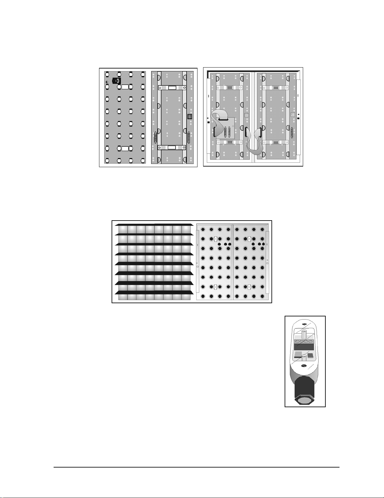
button thermostats. Venus 1500 systems will also have a master-echo board with in the enclosure.
Venus 4600 systems have no master-echo board within the fan controller enclosure, but instead route
the thermostat status back to the serial line interface board. Figure 6 shows the fan controller
enclosure, both with and without the enclosure cover. The master-echo board is on the right. The
Venus 4600 fan control enclosure looks similar, but lacks the master/echo board.
Figure 5: Button
Thermostat
Figure 6: Fan Controller Enclosure
Fiber Optic: A standard communication method using light (signal) transmitted through a glass fiber.
Fiber optic cable cannot exceed 1,200 feet. A signal converter may be required for fiber optic and
RS/232 configuration. This communication method is an option in both Venus 1500 and Venus 4600
Systems.
Junction Box: Small enclosure in which display data
traveling on serial cable from the computer is transferred to
RS/232 cable. The junction box must be located within 25
feet of the display. Only Venus 1500 systems using the
RS/232 communication option utilize this junction box.
Figure 7 illustrates a junction box.
Figure 7: Junction Box
1-4 Introduction
Page 11
Lampbank: A circuit board consisting of an array of lamps 8 pixels high by 4 pixels wide. Figure 8
shows a single lampbank, front and back. Two lampbanks mount to the rear of each lens/reflector
assembly as seen in Figure 9. If necessary, a lampbank can be easily removed from the lens/reflector
assembly.
Figure 8: Lampbank (Lamp Side)
Figure 9: Two Lampbanks on Lens /
Reflector Assembly
(Solder Side)
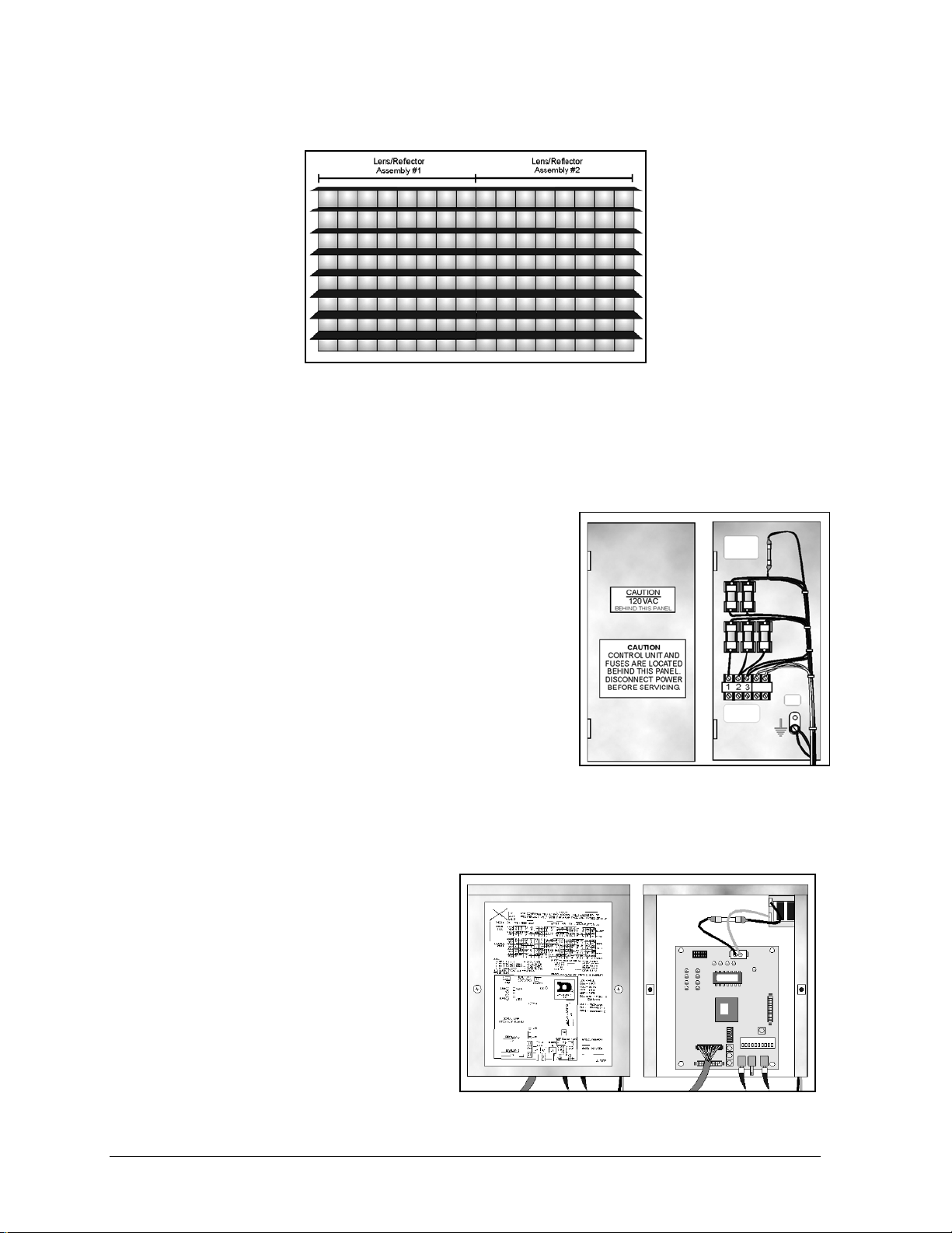
Lens/Reflector Assembly: Consists of reflectors, lenses and louvers. It is eight lenses high by eight
lenses wide. A lens/reflector assembly is easily removable for maintenance. Figure 10 illustrates the
front and back of a lens/reflector assembly. Two lampbanks mount on the rear of this assembly, as
seen in Figure 9.
Figure 10: Lens/Reflector Assembly
Light Detector: An optional device that senses ambient light levels. The light
detector and the controller operate together to dim the display when maximum
lamp brightness is not required. This saves energy and extends lamp life. Figure
11 shows the light detector for the Venus 1500 systems.
Louver: A piece of aluminum, eight pixels long, positioned above each row of
lamps to provide contrast and help direct light.
Figure 11: Light
Detector
Introduction 1-5
Page 12
Module: Consists of four lampbanks mounted to the backs of two lens assemblies. A module, Figure
12, is eight pixels high by 16 pixels wide. One transformer can power two modules (256 lamps).
Figure 12: Module
Modem: A standard communication method that utilizes standard phone transmission lines, and is an
option with the Venus 1500 System.
Pixel: Daktronics describes a pixel as being the point of light created by a single lamp behind a single
lens.
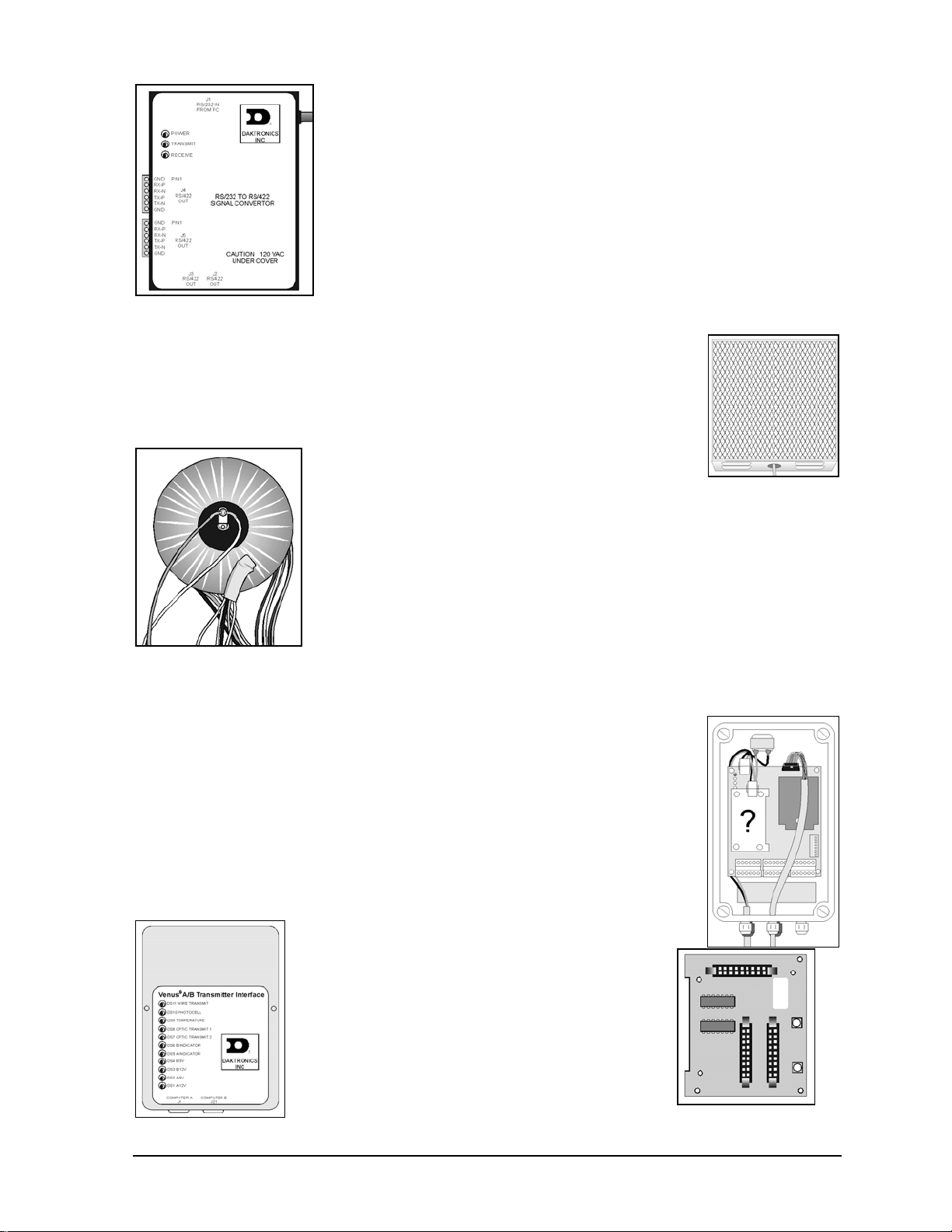
Power Termination Panel: Assembly in which incoming power
connects to the display. It mounts to the cabinet on the left end
(front view). Figure 13 shows the power termination panel
enclosure, both with the cover on the enclosure and with it
removed.
Quarter-Turn Fasteners: A type of latching mechanism found
on many Daktronics assembly enclosures. Using a Phillips
screwdriver, turn the fastener one-quarter-turn counter-clockwise
to release the latch and one-quarter-turn clockwise to secure the
latch.
RS/232: A standard PC communication type with a maximum
Figure 13: Power Termination Panel
cable length of 25 feet (8 meters).
RS/422: A standard differential communication type with a maximum cable length of 4,000 feet (1.2
kilometers).
Serial Line Interface (SLI): The controller
board used in Venus 4600 display systems. The
serial line interface (also called a line receiver)
receives signal from the controller computer via
fiber optic cable and routes it to the display.
Figure 14 illustrates the metal enclosure that
houses the serial line interface, both with the
enclosure cover in place and with the enclosure
cover removed. The serial line interface board is
seen on the right.
Figure 14: Serial Line Interface
1-6 Introduction
Page 13
Sign Address: An identification number assigned to each sign of a
network. The control software uses the address to locate and
communicate with each display. Displays on the same network cannot
have the same address.
Signal Converter: A Daktronics-supplied unit that converts the data
from RS/232 to RS/422. The signal converter is used in Venus 1500
RS/422 systems. Figure 15 shows the converter.
: SunSpot displays, also called monochrome displays, use
Figure 15: Signal
Converter
SunSpot
only one color lens - usually white. “SunSpot” is a registered trademark
of Daktronics, Inc.
Temperature Sensor: The temperature sensor is an optional device that
monitors temperature outside the display. The temperature sensor can be used to
offer “time and temperature” updates. Figure 16 shows a common temperature
sensor. Daktronics offers many enclosure styles.
Transformer: The device that transforms incoming
AC voltage to the operational AC voltage required by
the display electronics. Figure 17 illustrates a
transformer.
Figure 16: Temp
Sensor
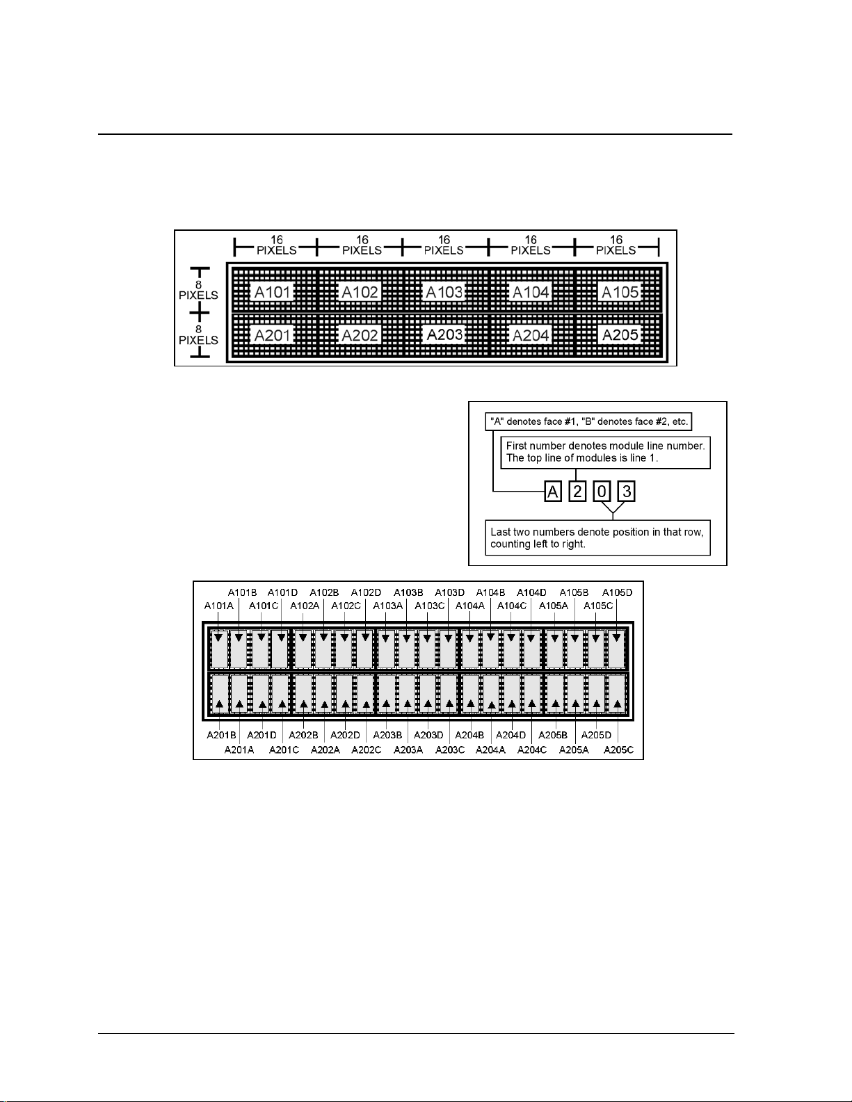
Venus 1500 Controller: The type of controller used in Venus 1500
display systems. It consists of a controller board, MDC (multipurpose
display controller) board, address board, and possibly a fiber optic or
modem board, depending on display configuration. The controller receives
data from the controller computer via RS/232 cable, RS/422 cable, fiber
Figure 17: Transformer
optic cable or modem/phone cable. The data then routes to the rest of the
display. Figure 18 illustrates the Venus 1500 controller in its enclosure.
The ‘?’ indicates the position of a fiber optic or modem board, if used.
Venus 1500 System: A display configuration that uses a controller computer
running Venus 1500 software to control a display housing a Venus 1500
controller. Venus 1500 systems can use any one of four methods to transmit data
from the controller computer to the display: RS/232, RS/422, fiber optic or
modem/phone cable. This display is set up for one of these methods.
Venus 4600 System: A display configuration that uses a controller computer
running Venus 4600 software to control a display housing a serial line interface.
Venus 4600 systems transmit data from the controller computer to the display
over fiber optic cable.
Venus A/B Transmitter Interface: A Daktronicssupplied unit used to convert RS/232 signal to fiber
optic signal. Venus 4600 Systems uses this. Figure
19 shows the transmitter interface.
Figure 18: Venus
1500 Controller
Vertical Shift Board (VSB): Circuit board
mounted to the back of the left-most (front view)
lampbank in each row of modules. It routes data
from the controller both down the row and to the
Figure 19: Venus A/B
Transmit I/F
VSB below it. Figure 20 shows the VSB. Figure 9
shows the VSB on a lampbank. The vertical shift
board is also known as a vertical shift register
Figure 20: Vertical
Shift Board
Introduction 1-7
Page 14
(VSR).
1.4 Daktronics Nomenclature
The Daktronics module numbering system assigns numbers to modules to aid in wiring and
troubleshooting. Remember, a module is two, side-by-side lens/reflector assemblies. Figure 21
illustrates the numbering on a typical 16x80 pixel small matrix display. Figure 22 explains the
meaning of the module numbering.
Figure 21: Module Numbering (16x80 Display) – Front View
In addition, lampbanks also have a numbering system.
There are two lampbanks mounted on the back of each
lens/reflector assembly. Therefore, there are four
lampbanks per module. Figure 23 illustrates this
lampbank numbering. It uses the same first four digits as
the module numbering system, but with an A, B, C or D
at the end to indicate whether it is the first, second, third
or four lampbank on that module.
Figure 23: Lampbank Numbering (16x80) - Front View
Figure 22: Module Numbering Detail
1-8 Introduction
Page 15

In addition, when using Daktronics drawings it may also be helpful to know the following.
• “F” denotes a fuse (F1, F2, F3…)
• “T” denotes a transformer (T1, T2, T3)
• “TB” denotes a termination block – power or signal.
• “A” denotes an assembly. These are divided according to power or signal.
Power assemblies consist of a number of power components, usually within a common enclosure.
For instance, a power termination block (TB41) may be located within a power termination panel
enclosure (A41). A second power termination panel has the label A42, a third A43, etc.
Signal assemblies consist of a number of signal routing or transmission components, usually
within a common enclosure. For instance, the enclosure housing the Venus 1500 controller or
serial line interface for this display is A31.
Introduction 1-9
Page 16

Page 17
Section 2: Mechanical Installation
The Daktronics engineering staff must approve any changes that may affect the weather
tightness or cooling ability of this display. This includes, but is not limited to:
• Border shrouding
• Back sheets
• Cooling fans
• Fan filters
• Filler panels
Submit detailed drawings of the proposed changes to our engineering staff for evaluation and
approval or the warranty will be null and void.
Appendix B contains two copies of the Installation Quality Checklist. It covers both mechanical and
electrical installation. This form is intended to assist in display installation and assure its dependable
operation. Make sure to act upon each item of the checklist. Following installation, return one copy to
Daktronics Customer Service to receive a free set of replacement air filters. Contact Daktronics
Customer Service if any product quality questions or concerns should arise.
2.1 Support Column Selection
Support column size is dependent on the height and total wind loading of the display and any other
signage attached, such as advertising panels.
Column selection is critical; only a qualified individual should do this.
It is the installer’s responsibility to specify the exact type of column and number of columns used.
Using more columns generally allows smaller columns.
2.2 Lifting the Display
The top of the display (or display sections) will be equipped with eyebolts to lift the unit. Take special
care not to exceed the rated load of the eyebolts. Refer to the information in Appendix B labeled Eye
Bolts to determine the allowable load of the eyebolts shipped with the display.
Figure 24 illustrates both the correct (left example) and the incorrect (right example) method of lifting
a display. Lift the display as shown on the left, with the lifting bar.
Stress on the eyebolts increase as the angle
between the cable and the display top
decreases.
Use every lifting point provided!
Do not attempt to permanently support the
display by the eyebolts.
If mounting this display outside, make sure water or moisture doesn’t get into the display.
Figure 24: Display Lifting
Mechanical Installation 2-1
Page 18
1. Inspect the top and sides of the display for any holes that may allow moisture to enter the display.
If the eyebolts were removed, plug the holes with bolts and the rubber sealing washer that came
with the eyebolt.
2. Plug and seal the eyebolt holes and any other openings that may allow water to enter the display
with silicone or another waterproof sealant.
CAUTION: Fully attach backsheets to the display cabinet with all of the screws prior to
lifting the display with the eye bolts. The backsheets provide structural support to the cabinet.
Lifting the display with the backsheets removed may cause the cabinet members to twist,
compromising the structural integrity and/or squareness of the display frame. If the display
frame is not square, normal waterproofing measures may prove inadequate, leading to moisture
related problems for the electronics.
2.3 Cabinet Mounting
Reference Drawing:
Mounting Example, 2½
The method used to mount displays can vary greatly from location to location. For this reason, this
manual only addresses general mounting topics. If this display was part of a custom contract, consult
the shop drawing in Appendix A for mounting information.
Before beginning the installation process, verify the following:
• The mounting structure will provide a straight and square frame for mounting the display.
• The mounting structure will not give way at any unsupported points after mounting the display.
Correct any deficiencies before beginning the installation process.
It is the responsibility of the installer to ensure the installation will agree with local codes. The
mounting hardware is also the responsibility of the installer.
The 9 x 1¾ x 1¾ channel used in this display requires supporting the display every eight feet with a
maximum overhang of three feet on each end of the display. The distribution of these supports is to be
symmetrical. This requires a minimum of two supports.
Drawing A-114676 illustrates one of the many ways a small matrix display may be mounted. To
mount a display as seen in the drawing complete the following steps:
1. Remove the four pieces of bar stock from the display. These flat pieces of metal reinforce the
display cabinet at the mounting points.
2. Since bolts or rods will be run on each side of each
column, it will be necessary to drill two holes in both the
bar stock and the cabinet frame at the support points.
Refer to Figure 25.
3. Drill holes in the bar stock and through the cabinet frame.
Run bolts to the angles on the opposite side of the
columns.
4. Secure the display firmly in place.
˝ Small Matrix....................................................Drawing A-114676
Figure 25: Possible Mounting Method
2-2 Mechanical Installation
Page 19
When mounting the display take note of the following:
• Keep ½-inch clearance below the drain holes in the bottom of the display.
• Do not obstruct airflow to the display fans. Refer to Drawing A-114676.
• Power and signal terminations require access to the inside of the display. Avoid mounting the
display in a manner that hinders access to the display face.
• The Daktronics engineering staff must first approve any modifications to the display ventilation
system.
You must properly seal the eyebolt holes on top of the display cabinet to prevent water from
entering the unit and damaging the electrical components.
Complete the following steps if leaving the eyebolts in the display.
1. Verify the eyebolts are firmly in place. From time to time eyebolts will loosen slightly from
shipping vibration.
2. If the eye bolts need tightening, keep in mind they need only be snug. Over-tightening will crush
the rubber sealing washers, rendering then ineffective.
3. Apply silicone sealant around the base of the eyebolts on top of the cabinet.
Complete the following steps if removing the eyebolts from the display.
1. Remove and discard the eyebolts, but keep the rubber sealing washers.
2. To plug the eyebolt holes, insert half-inch bolts through the rubber sealing washers and into the
eyebolt holes from the top of the display cabinet.
3. Tighten the bolt only as much as is needed to hold the bolt snugly in place. Over-tightening will
crush the rubber sealing washers, rendering then ineffective.
4. On the top of the cabinet, apply silicone sealant around the head of each bolt.
Inspect the entire display for any holes or gaps that may allow
water to enter the display. Use silicone sealant to close any such
openings.
The filters of 1600 series small matrix display are located on the
bottom exterior of the display cabinet. If mounting an
advertising panel or other structure beneath this display, 2.5
inches of clearance must be present in order to remove the
filters. Refer to Figure 26.
The amount of clearance between the display and the ad panel
or structure can also affect display ventilation. Refer to Section
2.5 to calculate the amount of clearance required for adequate
display cooling.
Figure 26: Bottom Clearance
Filter removal is addressed in Section 4.3, Filters.
2.4 Light Detector and Temperature Sensor Installation
Refer to ED9490 in Appendix C for light detector installation and ED9489 in Appendix C for
temperature sensor installation information.
Mechanical Installation 2-3
Page 20
2.5 Display Ventilation Requirements
Reference Drawings:
Mounting Example, Small Line Displays...............................................Drawing A-101424
Label, Filter Clearance..........................................................................Drawing A-141064
Daktronics small matrix displays use fans to prevent overheating. The fans bring air into the cabinet
from the bottom of the display, creating positive pressure within the display. The fans then force out
the warm air within the display through small gaps above each of the lenses, cooling the lamps and
lowering the internal temperature of the cabinet. This continuous cycle of airflow extends the life of
the lamps and decreases the maintenance costs associated with overheating.
If mounting another sign or structure on top
of one another, maintain a minimum of 2
1
/2O. This is to ensure proper airflow through
the sign and to allow easier access for filter
removal. Refer to Figure 27 and Drawings
A-101424 and A-141064.
In some circumstances it may be necessary,
or desirable, to mount a small matrix display
within another structure or to “skin over” one
or more displays. If enclosing a display in
this nature, adequate openings must exist in
the outer structure for air intake.
If enclosing a small matrix display within
another structure or “skinned over,” observe
the following specifications to prevent
display damage and premature lamp failure:
Figure 27: Minimum Clearance for Sign Bottom
• Provide twelve square inches of unobstructed opening per module for adequate display cooling.
Make allowances to compensate for the percentage of screen in the material covering the openings
in the enclosed structure.
• If forcing air into the enclosed area, it should run at 110 cubic feet per module (one module = 20"
x 40" display active area or eight rows x 16 columns of lamps).
For example, a 16x80 double-face, small matrix display inside an enclosed structure would require
240 square inches, or 1.7 feet, of unobstructed opening in the bottom of the center cabinet.
(2 displays (16x80 pixel size))/128 pixels per module = 20 modules
(2(1280))/128 = 20 modules
2560/128 = 20 modules
20 modules x 12 square inches = 240 square inches or 1.7 square feet
Also, if forcing air into an enclosed display, adhere to the following filter specifications:
• The effective filter area is to be no less than 2.3 square feet per 1.0 square feet of filter face area.
• The filter media is to have an average arrestance (resistance to debris) of 90-92%.
• Initial resistance should not exceed 0.48 w.g. (water gauge) at 500 fpm (feet per meter).
2-4 Mechanical Installation
Page 21
Submit any plans for filtering air in an enclosed display to the Daktronics engineering staff for
evaluation and approval or the warranty will be null and void.
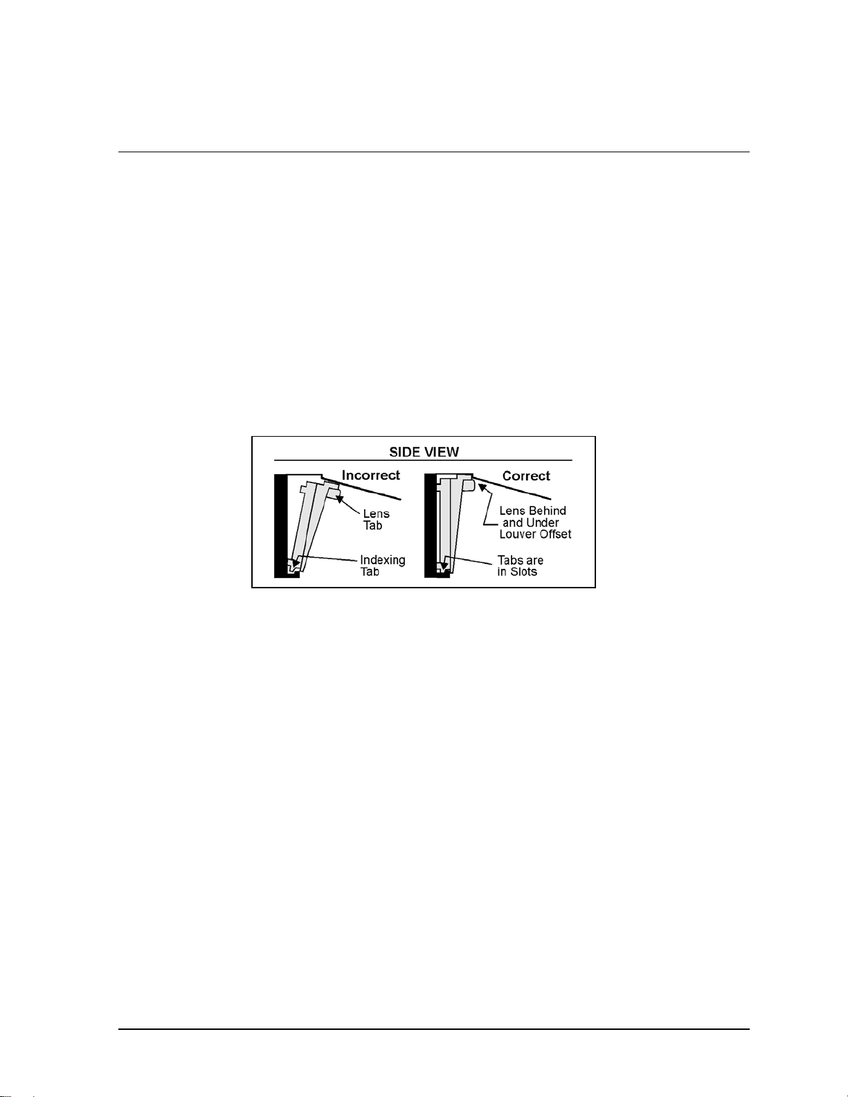
2.6 Verifying Correct Lens and Module Position
The final steps of mechanical installation involve verifying the proper positioning of all lenses upon
their respective lens/reflector assemblies and that all modules engage fully into the cabinet.
Look down the rows of louvers from either end of the display and secure all lenses properly. Lenses
not secured properly are easily noticeable as the lens removal tab, or the lens itself, will not be in
alignment with the other lenses or lens removal tabs of that row.
Refer to Figure 28 and the following steps to return a lens to its correct position.
1. First, insert the bottom indexing tabs into the slots. There is one indexing tab on each bottom
corner of the lens.
2. While gently pushing the above louver upward, grab the lens tab and push the top of the lens
behind and under the louver offset. Only push the louver upward enough to allow the lens to snap
into position behind the offset.
3. Release the louver and verify the lens aligns with others in the row.
Figure 28: Correct Lens Position
Also, ensure that the rows of louvers are in proper alignment. If any rows seem out of position, this
may indicate the one, or both, sides of the lens/reflector assembly do not engage fully into the cabinet.
If this is the case, a firm push to both sides of the module at the same time should snap the module into
place.
Mechanical Installation 2-5
Page 22

Page 23
Section 3: Electrical Installation
Appendix B contains two copies of the Installation Quality Checklist. It covers both mechanical and
electrical installation. This form assists in display installation and assures its dependable operation.
Address each item on the checklist. Following installation, return one copy to Daktronics Customer
Service to receive a free set of replacement air filters. Contact Daktronics Customer Service if any
product quality questions or concerns should arise.
3.1 Common Connectors
This display uses many different types of connectors for power and signal termination. Take special
care when disengaging any connector so as not to damage the connector, the cable or the circuit board.
When pulling a connector plug from a jack, do not pull on the wire or cable; pull on the jack
itself. Pulling on the wires may damage the connector.
The following information presents some common connectors encountered during display
maintenance. These include ribbon cable connectors, Mate-n-Lok connectors, Phoenix-style
connectors, fiber optic connectors, termination panels and termination blocks, and tab connectors.
Some displays do not use all of these connectors.
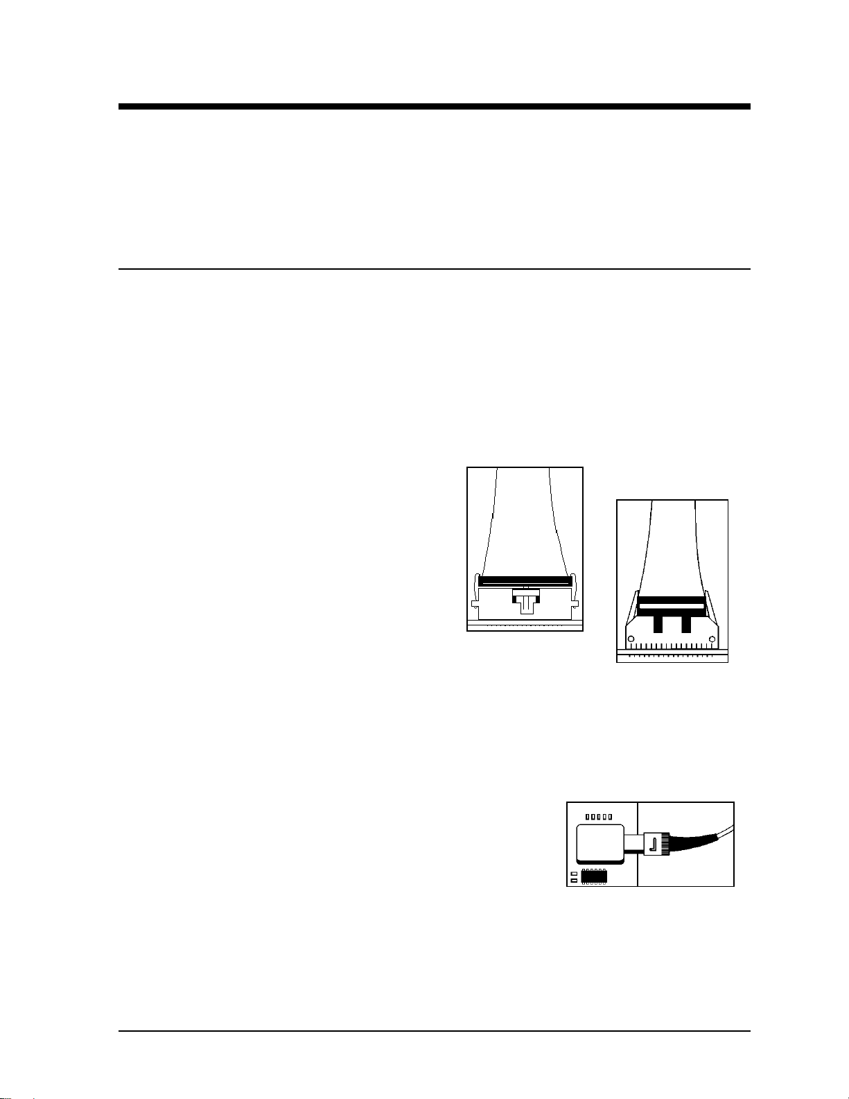
1. Ribbon Cable Connectors:
Daktronics uses a variety of ribbon cables and
ribbon cable connectors. Figure 29 and Figure 30
show two of the most common ribbon cable
connectors. To disconnect ribbon cable connector
#1, squeeze the metal locking clips inward and
pull the plug out of the jack. To disconnect ribbon
cable connector #2, pull each of the plastic
locking arms outward and remove the plug.
Before replacing a ribbon cable connector, spray
it with DeoxIT
™
contact cleaner to remove any foreign matter that may
Figure 29: Ribbon
Cable Connector 1
cause signal problems. In addition, apply a generous amount of CaiLube
protector paste to the plug before inserting it into the jack. This paste will protect both the plug
and the jack from corrosion. Both the DeoxIT and the CaiLube are in the tool kit accessories
package included with this display. Refer to the replacement parts list in Section 4.15 if additional
supplies of either are needed.
2. Fiber Optic Connectors:
At each end of a fiber optic cable is a “twist-on” connector. To
remove the fiber plug from its jack, push it toward the jack and
twist it counter-clockwise until the plug can pull free. Figure 31
shows a common type of fiber optic connector.
Figure 30: Ribbon
Cable Connector 2
™
Figure 31: Fiber Optic
Connector
Electrical Installation 3-1
Page 24
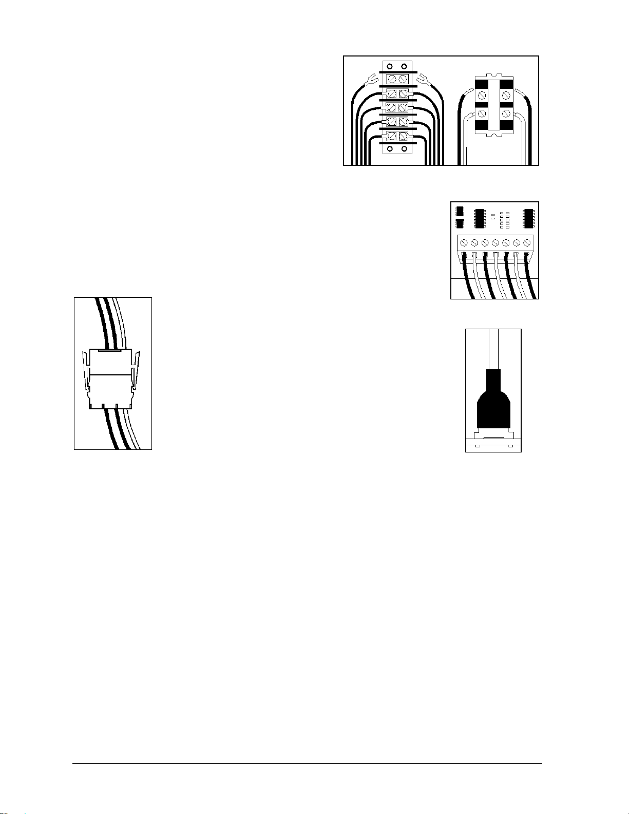
3. Termination Panels & Termination Blocks:
Termination panels and termination blocks connect
internal power and signal wires to wires of the same
type coming into the display from an external
source. Most signal wire comes with forked
connectors crimped to the ends of the wire. Power
wires need to have one-half inch of insulation
stripped from the end of the wire prior to
termination. Tighten all screws firmly to ensure a
good electrical connection. Refer to Figure 32.
Figure 32: Termination Panel (Left) and
Termination Block (Right)
4. Phoenix-Style Connectors:
Phoenix-style connectors, which are usually green, terminate signal on
circuit boards. Refer to Figure 33. Strip one-quarter inch of insulation from
the wire prior to termination. To remove a wire, turn the above screw
counter-clockwise to loose the connectors grip on the wire. To insert a
wire, push the bare wire into the connector and turn the above screw
clockwise to lock the wire into place.
5. Mate-n-Lok™ Connectors:
The Mate-n-Lok connectors found in this display are
white and come in a variety of sizes. Figure 34 illustrates a
four-pin Mate-n-Lok connector. To remove the plug from
the jack, squeeze the plastics locking clasps of the side of
the plug and pull it from the jack.
4. Tab Connectors:
The tab connector, illustrated in Figure 35, is in most
Daktronics displays. Grab the connector on the plastic
terminal cover when removing. Do NOT pull it off the tab
Figure 34:
Mate-n-Lok
Connector
by pulling on the wire.
Figure 33:
Phoenix Connector
Figure 35: Tab
Connector
3-2 Electrical Installation
Page 25
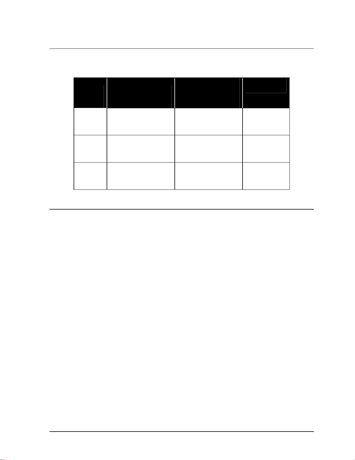
3.2 Display Power Requirements
The following table summarizes the power requirements for the various 1600 series, 2.5-inch small
matrix displays. Power stated is per display face.
Display
Size
8 x 48
8 x 64
8 x 80
8 x 96
16 x 48
16 x 64
16 x 80
16 x 96
24 x 48
24 x 64
24 x 80
24 x 96
120/208 3 Phase
4 Wire Plus Ground
(In Amps)
8
16
16
16
16
24
33
33
24
33
41
49
120/240 Single
Phase
3 Wire Plus Ground
(In Amps)
16
16
24
24
24
33
41
49
41
49
65
73
Total
Watts
2938
3917
4896
5875
5875
7834
9792
11750
8813
11750
14688
17626
3.3 Checking Line Voltage & 24-Hour Voltage Monitoring
Prior to display installation, perform a two-part voltage check. This is a necessary step taken to
maximize lamp life. By looking-up the line voltage on the table in this sub-section, you can calculate
the estimated lamp life and, if necessary, take steps to extend it.
Appendix C has two forms titled “Display Power Report.” This form records three different voltage
readings.
1. Line voltage, addressed in this sub-section.
2. 24-hour monitoring, which also addressed in this sub-section
3. Lamp voltage, checked after the display is powered-up for the first time.
When complete, send one of the “Display Power Report” forms to Daktronics Customer Service. The
other form is for the customer’s records.
To complete the line voltage check, take a line reading of each phase and record the results on each of
the power reports in Appendix A. Then place a voltage monitor on the phase with the highest reading
for 24 hours. Also, write down the maximum and minimum voltages recorded on each of the power
reports.
If lacking the proper equipment to accurately monitor line voltage, consider the following options.
• Have the local power company take the readings.
• Rent the equipment from a local service company.
• Have Daktronics Customer Service recommend the proper equipment.
• Rent the equipment from Daktronics.
Electrical Installation 3-3
Page 26
If there is any reason to suspect large voltage fluctuations, place a recorder on the line for at least one
phase of the power for one week while the display operates normally. Contact Daktronics Customer
Service with respect to this recording.
Display brightness and lamp life are generally determined assuming an average incoming line voltage
of 120 volts AC at 60 hertz. If the line voltage varies from that value, it will affect both lamp life and
brightness. Lamp life results will also vary with programming style and use of dimming mode.
§ Lamp life predictions are for lamps operating in a laboratory with continuous operation in a stable
temperature and mechanical environment. Actual values will differ from predicted life because of
switched operation, varying temperature, mechanical vibrations due to wind, traffic and sign service
and actual hours of operation. Data is that of the manufacturer.
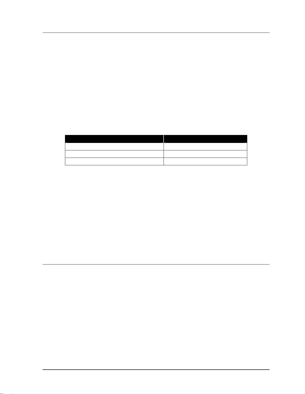
Lamp Voltage/Lamp Life with 23 VAC Secondary (T-1109 XFMR)
120 V Only 5 V Buck 5 V Boost
Line
Volts
18.90 19.72 3.42 35022 18.90 2.95 59271 20.60 3.98 20250
108 20.10 3.66 27530 19.27 3.16 46578 21.00 4.26 15923
110 20.48 3.91 21740 19.64 3.37 36770 21.40 4.55 12577
112 20.87 4.17 17242 20.01 3.60 29155 21.80 4.86 9978
113 21.06 4.30 15380 20.19 3.71 16003 22.00 5.01 8902
114 21.25 4.44 13733 20.38 3.83 23215 22.20 5.18 7950
115 21.44 4.58 12275 20.56 3.96 20748 22.40 5.34 7107
116 21.63 4.73 10983 20.74 4.08 18561 22.60 5.51 6359
117 21.83 4.88 9836 20.93 4.21 16621 22.80 5.68 5696
118 22.02 5.03 8818 21.11 4.34 14899 23.00 5.86 5107
119 22.21 5.18 7912 21.30 4.48 13367 23.20 6.04 4583
120 22.40 5.34 7107 21.48 4.61 12004 23.40 6.22 4117
121 22.59 5.50 6389 21.66 4.75 10790 23.60 6.41 3701
122 22.78 5.67 5748 21.85 4.89 9708 23.80 6.60 3331
123 22.98 5.84 5177 22.03 5.04 8742 24.00 6.80 3000
124 23.17 6.01 4666 22.22 5.19 7878 24.20 7.00 2704
125 23.36 6.18 4210 22.40 5.34 7107 24.40 7.20 2440
126 23.55 6.36 3801 22.58 5.50 6416 24.60 7.41 2203
127 23.74 6.55 3435 22.77 5.65 5797 24.80 7.63 1991
128 23.93 6.73 3106 22.95 5.82 5242 25.00 7.84 1801
129 24.13 6.92 2811 23.14 5.98 4744 25.20 8.07 1630
130 24.32 7.12 2547 23.32 6.15 4297 25.40 8.29 1477
Lamp
Volts
Candle
Power
Lamp
Life
Hours
Lamp
Volts
Candle
Power
Lamp
Life
Hours
Lamp
Volts
Candle
Power
Lamp
Life
Hours
If the line voltage is near or above 125 volts or a longer lamp life is desired, contact Daktronics for
transformer adjustment.
Contact a local electrician or the local power company if line voltage is substantially above or below
normal.
3-4 Electrical Installation
Page 27
3.4 Preparing the Display for Power & Signal Connection
Reference Drawings:
Shop Drawing, 7 or 8 High, 2 ½
Shop Drawing, 16 High, 2 ½
Shop Drawing, 24 High, 2 ½
When connecting power and signal to this display it is necessary to access the following items.
• Power termination panel.
• Display controller (Venus 1500 controller or serial line interface)
• Fan control enclosure – Venus 1500, 2V cabinet configurations only.
The shop drawings illustrate the locations of the above-listed items at the end of this section.
However, only one of the drawings is appropriate for this display. Use the following table to choose
the correct shop drawing.
If the display being installed is… Consult shop drawing…
7 or 8 high display (all lengths) Drawing A-114666
16 high display (all lengths) Drawing A-114667
24 high display (all lengths) Drawing A-114668
After locating the power termination panel and display controller on the shop drawing, complete the
following steps to ready the display for power and signal hook-up.
1. Remove the necessary lens/reflector assemblies to gain access to the termination panel and display
controller. Lens/reflector removal is addressed in Lens/Reflector Assemblies in Section 4.3.
Venus 1500 systems need only access the fan control enclosure if installing two displays together
in a 2V cabinet configuration. Venus 4600 systems do not need access to the fan control enclosure
regardless of cabinet configuration.
2. Remove the covers from the power termination panel, the display controller and, if needed, the fan
control enclosure.
Daktronics completes all internal power and signal wire routing and connecting prior to shipment.
˝..........................................................Drawing A-114666
˝................................................................Drawing A-114667
˝................................................................Drawing A-114668
3.5 Bringing Power to the Display
Reference Drawing:
Assy, Term Panel................................................................................ Drawing A-113974
Only qualified individuals should perform power routing and termination to the display. It is
the responsibility of the installer to ensure the installation will adequately meet local codes and
standards.
! Run power from the power distribution point to the termination panel of each display face.
! Run power separately to each display face.
! This power is run through conduit according to national and local electrical codes.
! Use the knockouts in the back sheet located near the termination panel for the conduit entrance
point. This area is marked with a label (“Recommended Pwr & Sig Entrance Location”).
! Power cannot route through the display. Do not use the support conduit, located inside the
display, for power routing.
Electrical Installation 3-5
Page 28

The following subsections address the routing of incoming power through a power disconnect switch
and the termination of incoming power at the display’s power termination panel. Daktronics completes
all power routing and connection within the display past the power termination panel prior to
shipment.
When terminating the incoming power to the term panel, balance the individual power phases as
evenly as possible. Current draw per line, as noted on the sales literature or schematic, is the high leg
current draw.
For a 2V display, bring power into both faces. The termination panel for the echo face is located in the
right end of the display. Connect power as stated above.
Power Disconnect Switch
Route power to the display through a fused disconnect switch capable of opening all ungrounded
power conductors. Locate this disconnect within the line of sight of any personnel performing
maintenance on the display. If locating the disconnect out of sight of the display, it must be able to
lock in the open position.
Due to the inrush current (momentary surge) created by the display on start-up, Daktronics
recommends using oversized current devices, high magnetic breakers or time delay fuses to
handle the momentary surge.
The Over Current Protection Device needs to match the fault current available in the power
delivery circuit. To determine the available fault current of circuit, have qualified personnel
perform an onsite fault current survey at the site.
The National Electrical Code requires the Amp Inrush Current (AIC) rating of the electrical
equipment in a circuit match the available fault current in the electrical circuit.
Because each installation is unique, Daktronics offers these instructions as guidelines only.
Daktronics assumes no liability if installation steps have been omitted or other necessary
procedures are not included in this manual.
Daktronics is not responsible for the quality of the power delivery system to the display. It is the
customer’s responsibility to ensure the undertaking of proper safety measures. Power and
signal wiring in the display must comply with local, state and national electrical codes, with the
correct cabling procedures for the installation determined and followed.
Power Termination at the Display
Incoming power connects to the power termination panel located within the left end of display.
Drawing A-113974 shows an example of a power termination layout. The appearance of other
termination panels will vary by sign size.
Complete the following steps to connect power to the termination panel.
1. Pull the power cable from the conduit to the termination panel.
2. Connect the white neutral wire (or wires) to the position labeled NEUT on TB41.
3. If terminating 120/240 single-phase power, connect the hot wires to the positions labeled L1
and L2 on TB41. If terminating 120/208 three-phase power, connect the hot wires to L1, L2
and L3 on TB41.
4. Apply a silicone sealant around the conduit where it meets the cabinet to prevent
water/moisture from entering the display.
3-6 Electrical Installation
Page 29

5. Refer to the following section, Section 3.5, for important information regarding display
grounding.
Grounding
Displays MUST be grounded according to the provisions outlined in Article 250 of the
National Electrical Code
Verification of ground resistance can be performed by the electrical contractor who is performing
the electrical installation. This service can also be performed by Scoreboard Sales and Service
personnel
The display system must be connected to earth-ground. Proper grounding is necessary for reliable
equipment operation. It also protects the equipment from damaging electrical disturbances and
lightning. The display must be properly grounded or the warranty will be void.
The material of an earth-ground electrode differs from region to region and from conditions
present at the site. Consult the National Electrical Code and any local electrical codes that
may apply. The support structure of the display cannot be used as an earth-ground electrode.
The support is generally embedded in concrete, and if in earth, the steel is either primed or it
corrodes, making it a poor ground.
®
. Daktronics recommends a resistance to ground of 10 ohms or less.
Power Installation
There are two considerations for power installation; installation with ground and neutral
conductors provided and installation with only a neutral conductor provided. These two power
installations differ slightly, as described in the following paragraphs:
Installation with Ground and Neutral Conductors Provided
For this type of installation, the power cable must contain an isolated earth-ground conductor.
Under this circumstance, do not connect neutral to ground at the disconnect or at the display.
This would violate electrical codes and void the warranty. Use a disconnect so that all hot
lines and neutral can be disconnected. Refer to Figure 36 for installation details. The National
Electrical Code requires the use of a lockable power disconnect within sight of or at the
display.
Electrical Installation 3-7
Page 30
Figure 36: Installation with Ground and Neutral Conductor Provided
Installation with Only a Neutral Conductor Provided
Installations where no grounding conductor is provided must comply with article 250-32 of
the National Electrical Code. If the installation in question meets all of the requirements of
article 250-32, the following guidelines must be observed:
• Connect the grounding electrode cable at the local disconnect, never at the display power
termination panel.
• A disconnect that opens all of the ungrounded phase conductors should be used.
• The neutral and the ground conductors should be bonded in the display power termination
panel.
Refer to Figure 37 for installation details.
Figure 37: Installation with only Neutral Conductor provided
3.6 Bringing Signal to the Display
Reference Drawings:
V1500 Signal Termination .....................................................................Drawing A-103727
Serial Line IF Signal Terms...................................................................Drawing A-103740
3-8 Electrical Installation
Page 31

System Riser Diagram (Serial Line IF)..................................................Drawing A-107196
System Riser Diagram (RS/422)...........................................................Drawing A-148859
System Riser Diagram (RS/232)...........................................................Drawing A-148870
System Riser Diagram (Fiber Optic).....................................................Drawing A-148878
System Riser Diagram (Modem)...........................................................Drawing A-148884
The method used to route and terminate signal cable at the display differs according to the type of
signal cable used. This is especially true for the Venus 1500 systems, which are available in the
following configurations.
• Venus 1500 system using RS/232 signal
• Venus 1500 system using RS/422 signal
• Venus 1500 system using modem/telephone cable
• Venus 1500 system using fiber optic signal
Venus 4600 systems use only one type of signal – fiber optic. Daktronics completes all internal signal
wiring prior to shipment.
The following sub-sections address signal cable connection for each of the previously listed signal
cable configurations. Refer to the information appropriate for this particular display.
Signal interconnect between displays in a 2V configuration is covered in Section 3.7.
Venus 1500 System Using RS/232 Signal
RS/232 systems use a two-conductor, shielded cable to transmit the RS/232 signal from the
junction box to the display controller. The cable is assigned the Daktronics part number W-1117.
Keep the following in mind when working with W-1117 cable.
• W-1117 cable should not be subjected to mechanical flexing after installation.
• It is not for direct burial.
• It should only be routed in a dedicated, grounded metallic conduit.
• It has a maximum length of 25 feet.
Complete the followings steps to connect signal to a Venus 1500 system using RS/232 cable.
1. Mount the junction box with 25 feet of the base of the display.
2. Route conduit and W-1117 cable from the junction box to the knockouts on the right side
(rear view) of the display – or master display if a 2V configuration is being installed.
3. Continue cable into the Venus 1500 controller enclosure fitting labeled “Signal In.”
4. Use the table within this sub-section titled “Venus 1500 RS/232 Signal Connection” to
terminate the W-1117 cable at the Venus 1500 controller and at the junction box.
• The connector labeled “RS/232 In” (TB1) is a six-position, Phoenix-style connector found
on the Venus 1500 controller board. Refer to Drawings A-103727 and A-148870 at the
end of this section.
• TB41 is the only termination panel within the junction box.
Venus 1500 RS/232 Signal Connection
J-Box Cabling RS/232 In (TB1)
Pin 1 (N.C)
Pin 2 (N.C.)
TB41-2 (RX-P) Clear Pin 3 (TX-P)
TB41-3 (GND) Shield Pin 4 (GND)
Electrical Installation 3-9
Page 32

TB41-1 (TX-P) Black Pin 5 (RX-P)
Pin 6 (N.C)
5. The controller computer connects to the 25-position connector (DB25) within the junction
box. Refer to Drawing A-148870 at the end of this section.
6. Apply silicone sealant around the signal conduit where it meets the display cabinet to prevent
water/moisture from entering the display.
Refer to Light Detector Installation - Venus 1500 Systems in Section 3.8 for instructions on
installing the light detector for this display. If ordering a temperature sensor, refer to Section 3.9
for temp sensor installation instructions.
If this display is one face of a two-face, 2V cabinet display configuration, refer to Section 3.7 for
instructions on running signal from the master to the echo unit.
Venus 1500 System Using RS/422 Signal
RS/422 systems use a six-conductor, unshielded cable to transmit the RS/422 signal from the
signal converter to the display controller. This cable consists of paired wires. It is Daktronics part
number W-1210. Keep the following in mind when working with W-1210 cable.
• Do not subject W-1210 cable to mechanical flexing after installation.
• It is not for direct burial.
• Only route it in a dedicated, grounded metallic conduit.
• It has a maximum length of 4,000 feet.
Complete the following steps to connect signal to a Venus 1500 system using RS/422 cable.
1. Route conduit and W-1210 cable from the control room to the knockouts on the right side
(rear view) of the display – or master display if installing a 2V configuration.
2. Continue cable into the Venus 1500 controller enclosure fitting labeled “Signal In.”
3. Use the table within this sub-section titled “Venus 1500 RS/422 Signal Connection” to
terminate the W-1210 cable at the Venus 1500 controller and at the signal converter.
• The connector labeled “RS/422 In” (TB2) is a six-position, Phoenix-style connector found
on the product board of the Venus 1500 controller. Refer to Drawings A-103727 and A-
148859.
• “J6” is one of two six-position, Phoenix-style connectors found on the side of the signal
converter. Each is clearly labeled.
Venus 1500 RS/422 Signal Connection
Sig. Conv. (J6) Cabling RS/422 In (TB2)
Pin 1 (GND) Red Pin 1 (GND)
Pin 2 (TX-P) Black Pin 2 (RX-P)
Pin 3 (TX-N) Brown Pin 3 (RX-N)
Pin 4 (RX-P) White Pin 4 (TX-P)
Pin 5 (RX-N) Blue Pin 5 (TX-N)
Pin 6 (GND) Green Pin 6 (GND)
4. The controller computer connects to the 25-position connector (DB25) on the signal converter
labeled “J1.” Refer to Drawing A-148859
3-10 Electrical Installation
Page 33

Refer to Light Detector Installation - Venus 1500 Systems in Section 3.8 for instructions on
installing the light detector for this display. If ordering a temperature sensor, refer to Section 3.9
for temp sensor installation instructions.
If this display is one face of a two-face, 2V cabinet display configuration, refer to Section 3.7 for
instructions on running signal from the master to the echo unit.
Venus 1500 System Using Modem/Telephone Cable
Modem systems use standard telephone cable routed through conduit to send data from the
controller computer modem to the display controller. The local telephone company must assist in
this installation. Ask a representative of the phone company which colors the TIP and the RING
for signal connection use.
The telephone lines must be standard, direct dial lines not run through a
switchboard/communications system.
Refer to Section 4.5 for an FCC notice regarding modem use.
Complete the following steps to connect signal to a Venus 1500 system using a modem and
telephone cable.
1. Route conduit and telephone cable to the knockouts on the right side (rear view) of the display
– or master display if installing a 2V configuration.
2. Continue cable into the Venus 1500 controller enclosure fitting labeled “Signal In.”
3. Remove the telephone terminal block cover and connect incoming wires using standard
telephone wire colors.
4. Replace the telephone terminal block cover.
5. One short RJ11 telephone cable plugs into the telephone terminal block and the jack labeled
“Phone” (J1) on the Venus 1500 controller modem board. The other short RJ11 cable plugs
into the jack labeled “RS/232 Out” (J2) on the Venus 1500 controller modem board and the
RJ11 jack on the Venus 1500 controller product board. Refer to Drawings A-103727 and A-
148884.
Refer to Section 3.8 for instructions on installing the light detector for this display. If ordering a
temperature sensor, refer to Section 3.9 for temp sensor installation instructions.
If this display is one face of a two-face, 2V cabinet display configuration, refer to Section 3.7 for
instructions on running signal from the master to the echo unit.
Venus 1500 System Using Fiber Optic Signal
Venus 1500 fiber optic systems use a four-fiber cable to transmit data from a signal converter in
the control room to the display controller. The cable is Daktronics part number W-1376. Keep the
following in mind when working with W-1376 cable.
• Do not subject W-1376 cable should to mechanical flexing after installation.
• It is suitable for direct burial or routing in conduit.
• It has a maximum length of 1,500 feet.
Complete the following steps to connect signal to a Venus 1500 system using fiber optic cable.
1. Route conduit (if needed) and W-1376 cable from the control room to the knockouts on the
right side (rear view) of the display – or master display if installing a 2V configuration.
2. Continue cable into the Venus 1500 controller enclosure fitting labeled “Signal In.”
Electrical Installation 3-11
Page 34

3. Use the table within this sub-section titled “Venus 1500 Fiber Optic Connection” to connect
fiber optic cable at the signal converter and the Venus 1500 controller fiber optic board.
• The Venus 1500 fiber optic board mounts on the Venus 1500 controller board within the
Venus 1500 enclosure. Refer to Drawings A-103727 and A-148878.
• The fiber optic connectors on the side of the signal converter are clearly labeled.
Venus 1500 Fiber Optic Signal Connection
Signal
Converter
RX-Out (J3) ----- TX-In (J4)
TX-Out (J2) ----- RX-In (J5)
Cabling Venus 1500
Fiber Board
4. The controller computer connects to the nine-position connector (DB9) on the signal converter
labeled “J1.” Refer to Drawing A-148878 found at the end of this section.
Refer to Light Detector Installation - Venus 1500 Systems in Section 3.8 for instructions on
installing the light detector for this display. If ordering a temperature sensor, refer to Section 3.9
for temp sensor installation instructions.
If this display is one face of a two-face, 2V cabinet display configuration, refer to Section 3.7 for
instructions on running signal from the master to the echo unit.
Venus 4600 System Using Fiber Optic Signal
Venus 4600 fiber optic systems use a two-fiber cable to transmit data from an A/B interface in the
control room to the serial line interface within the display. The cable is Daktronics part number
W-1242. Keep the following in mind when working with W-1242 cable.
• Do not subject W-1242 cable to mechanical flexing after installation.
• It is suitable for direct burial or routing in conduit.
• It has a maximum length of 1,500 feet.
Complete the following steps to connect signal to a Venus 4600 system using fiber optic cable.
1. Route conduit (if needed) and W-1242 cable from the control room to the knockouts on the
right side (rear view) of the display – or master display if installing a 2V configuration.
2. Pull fiber optic cable to the bottom of the serial line interface board.
3. Connect fiber cable to J8, fiber optic input, on the serial line interface board and to J8 (RX) on
the A/B interface. Refer to Drawings A-107196 and A-103740.
4. The controller computer connects to the 15-position connector (DB15) on the A/B interface.
Refer to Drawing A-107196.
If the optional photo/temp sensor was ordered with this display refer to Optional Photo/Temp
Sensor Installation - Venus 4600 Systems in Section 3.8.
If this display is one face of a two-face, 2V cabinet display configuration, refer to Section 3.7 for
instructions on running signal from the master to the echo unit.
If this display does not have a photo/temp sensor and is not one face of a two-face, 2V cabinet
configuration, refer to Section 3.10.
If this display is one face of a two-face, 2V cabinet display configuration, refer to Section 3.7 for
instructions on running signal from the master to the echo unit.
3-12 Electrical Installation
Page 35

3.7 Interconnect of 2V Displays
Reference Drawing:
Interconnect, 2V Drawing A-104023
Shop Drawing, 7 or 8 High, 2 ½
Shop Drawing, 16 High, 2 ½
Shop Drawing, 24 High, 2 ½
The procedure for interconnecting 2V displays differs for Venus 1500 and Venus 4600 systems.
Drawing A-104023 provides a general idea how signal cable routes between display faces in both
Venus 1500 and Venus 4600 systems.
In order to provide a signal interconnect between two (or more) Venus 1500 system displays the
lens/reflector assemblies must be removed from in front of both the Venus 1500 display controller and
the fan control enclosure. Venus 4600 systems do not have a fan control enclosure. Therefore, remove
only the lens/reflector assemblies in front of the serial line interface.
The shop drawing for this display shows the locations of the display controller (Venus 1500 controller
or serial line interface) and the fan control enclosure (Venus 1500 only). The following table explains
which shop drawing is used for which display.
If the display being installed is… Consult shop drawing…
7 or 8 high display (all lengths) Drawing A-114666
16 high display (all lengths) Drawing A-114667
24 high display (all lengths) Drawing A-114668
Refer to Lens/Reflector Assemblies in Section 4.3 for instructions on removing lens/reflector
assemblies.
Having removed the needed lens/reflector assemblies, proceed to the appropriate sub-section for this
display.
˝..........................................................Drawing A-114666
˝................................................................Drawing A-114667
˝................................................................Drawing A-114668
Venus 1500 Systems
On all Venus 1500 systems, signal comes from the controller computer to the Venus 1500
controller in the independent (master) display. That signal then relays to the echo display over two
25-foot-long cables: one being 12-pin and the other being 20-pin.
The two 25-foot cables ship in the echo display. The location of the cables within the display is
labeled on the back sheet.
When placed back-to-back, the displays can have a maximum separation of five feet if the display
is 144 pixels long. For every 16 pixels less in length, the displays can be two feet farther apart.
Complete the following steps to interconnect signal between the master and echo displays.
1. Route two-inch conduit and both the 12 and 20-pin cables between the displays. Daktronics
provides knockouts on the rear of the displays for attaching conduit.
2. Within the echo display, the 20-pin connector plugs into the “Input” jack of the vertical shift
board located at the upper-left end (front view) of the display. The vertical shift board attaches
to the back of the lampbank of the rear of the lens/reflector assembly. Eight-pixel-high
displays only have one lens/reflector assembly on the left end of the display.
3. Still within the echo display, the 12-wire cable routes from TB31 into the 12-position jack of
Electrical Installation 3-13
Page 36

the fan control enclosure of the master display.
4. In the master display, plug the 20-pin connector into the output jack (J5) of the master/echo
board in the fan controller enclosure.
5. Still in the master display fan control enclosure, plug the other end of the 12-pin connector
into the output (J3) of the master/echo board.
6. Replace all covers and lens/reflector assemblies.
7. Apply silicone sealant around conduit attachment points to prevent moisture/water from
entering the display.
Refer to Light Detector Installation - Venus 1500 Systems in Section 3.8 for instructions on
installing the light detector for this display. If ordering a temperature sensor, refer to Section 3.9
for temp sensor installation instructions.
If the light detector and temperature sensor come installed, refer to Section 3.10
Venus 4600 Systems
On all Venus 4600 systems, signal comes from the controller computer to a serial line interface
board in either display. The master display houses the serial line interface that receives signal
directly from the controller computer. The serial line interface of the remaining display,
considered the echo display, receives signal over fiber optic cable from the serial line interface in
the master display.
Fifty feet of fiber optic cable ships in the echo display. The location on the cable within the
display is labeled on the back sheet.
When placed back-to-back, the displays can have a maximum separation of 25 feet if the display
is 96 pixels long. For every 16 pixels less in length, the displays can be three feet farther apart.
Complete the following steps to interconnect signal between the master and echo displays.
1. Route conduit and fiber optic cable between the displays. Daktronics provides knockouts on
the rear of the displays for attaching conduit.
2. Within the echo display, connect the fiber optic cable to the J8 (RX) plug of the serial line
interface.
3. Within the master display, connect the fiber optic cable to the J6 or J7 (TX) plug of the serial
line interface.
4. Replace all covers and lens/reflector assemblies.
5. Apply silicone sealant around conduit attachment points to prevent moisture/water from
entering the display.
If the optional photo/temp sensor came with this display refer to Light Detector Installation -
Venus 1500 Systems in Section 3.8.
If the optional photo/temp sensor comes already installed, proceed to Section 3.10.
3.8 Controlling Display Brightness
Daktronics 1600 series small matrix displays have the ability to alter the brightness of the lamps via
the controller software. This feature increases the impact of the display and extends the life of the
lamps. During the day, lamps need to be brighter to compete with sunlight. During the night, lamps
can be dimmer because they are not competing with sunlight and because lamps tend to glare at night
if too bright.
3-14 Electrical Installation
Page 37

Lamp brightness levels are set using the Venus software running on the controller computer. Control
brightness by either manually configuring a bright/dim schedule or by letting the optional light
detector adjust lamp brightness as needed.
Following are the optional light detector installation instructions for both Venus 1500 and Venus 4600
systems.
ED9067 and ED4602 contain operation instructions for the Venus 1500 and Venus 4600 software,
respectively. Use the appropriate software manual to configure the display for a light detector if using
one.
Light Detector Installation - Venus 1500 Systems
Instructions for mounting and connecting signal wire to the light detector are located with the light
detector in its box.
A light detector can easily connect to the Venus 1500 display controller as follows.
1. Route the light detector cable (Daktronics part
number W-1234) through conduit and into the
display.
2. Continue the cable into the controller box fitting
labeled “LIGHT.”
3. Strip the insulation and terminate wires to TB7 as
shown below. TB7 is near the lower-right corner
of the Venus 1500 controller product board, as
seen in Figure 38.
Light
Detector
+V Red Pin 1 (+5V)
GND Black Pin 2 (GND)
P Green Pin 3 (Light - P)
N White Pin 4 (Light - N)
Field
Cabling
Venus 1500 Controller Term
If a temperature sensor was ordered with this display, refer to Optional Temp Sensor Installation
- Venus 1500 Systems in Section 3.9 for installation instructions.
Proceed to Section 3.10 if all the following statements are true.
• Signal from the controller computer routes and connects to the Venus 1500 controller within
the display.
• The light detector connects to the Venus 1500 controller.
• A temperature sensor was not ordered with this display or is already installed.
• If this is a 2V, multi-face display, signal interconnects between the displays.
Figure 38: TB7 on Venus 1500
controller
Block (TB7)
Optional Photo/Temp Sensor Installation - Venus 4600 Systems
Instructions for mounting and connecting signal wire to the light detector are located with the light
detector in its box.
Venus 4600 systems usually have a combination light and temperature sensor. The two devices
integrate into a common circuit board. There is also a photocell-only option available. The only
Electrical Installation 3-15
Page 38

difference between the two options is the number of wires running from the sensor to the Venus
A/B transmitter interface, where the sensor connects.
Complete the following steps to connect the photo/temp sensor to the Venus A/B transmitter
interface.
1. Remove the cover from the Venus A/B transmitter interface. Removing
each of the two screws on the face of the enclosure and lifting the cover
away accomplishes this.
2. Route cable and conduit from the sensor to the A/B interface.
3. Strip the wire insulation and terminate to TB1 in the A/B interface as shown
in the table below. Figure 39 illustrates the location of TB1 on the A/B
interface circuit.
The wire colors correspond to the wire colors leaving the sensor.
Wire
Color
White Pin 1 (Photo-P)
Black Pin 2 (GND-N)
Red Pin 3 (TMPV-P)
Brown Pin 4 (GND-N)
Green Pin 5 (TMPIN-P)
Shield Pin 6 (GND-N)
TB1 On A/B Interface
Circuit Board
Figure 39: TB1 on A/B
Interface
Not all wires above will be present if the temperature sensor is not included. If this is the case,
simply connect the wires that are present according to the above table.
Proceed to Section 3.10 if all the following statements are true.
• Signal from the controller computer routes and connects to the serial line interface within the
display.
• The photo/temp sensor ordered with the display has connected to the A/B transmitter
interface.
• If this is a 2V, multi-face display, signal has interconnected between the displays.
3.9 Optional External Temperature Sensor
Both Venus 1500 and Venus 4600 systems offer an optional external temperature sensor. This sensor
relays temperature information to the Venus software, which can then display the temperature data on
the display. This can be combined with the time to create a “time and temp” service.
Operation instructions for the Venus 1500 and Venus 4600 software are in ED9067 and ED4602,
respectively. Use the appropriate software manual to configure the display if using a temperature
sensor.
Optional Temp Sensor Installation - Venus 1500 Systems
Instructions for mounting and connecting signal wire to the temperature sensor are located with
the temp sensor in its box.
Connect the temp sensor to the Venus 1500 display controller as follows.
3-16 Electrical Installation
Page 39

1. Route the temp sensor cable (Daktronics part number W-1234) through conduit and into the
(
(
)
(
)
display.
2. Continue the cable into the controller box fitting labeled “TEMP.”
3. Strip the insulation and terminate wires to TB7 as shown below. TB7 is found near the lower-
right corner of the Venus 1500 controller product board, as seen in Figure 35 in Light
Detector Installation - Venus 1500 Systems in Section 3.8.
Temp
Detector
P Green Pin 5 (Temp - P)
N White Pin 6
+V Red Pin 7
GND Black Pin 8
Field
Cabling
Venus 1500 Controller Term
Block (TB7)
Temp - N)
+5V
GND
Proceed to Section 3.10 if all the following statements are true.
• Signal from the controller computer has routed and connected to the Venus 1500 controller
within the display.
• The light detector and/or temp sensor ordered with the display have connected to the Venus
1500 controller.
• If this is a 2V, multi-face display, signal has interconnected between the displays.
Optional Photo/Temp Sensor Installation - Venus 4600 Systems
Instructions for mounting and connecting signal wire to the light detector are located with the light
detector in its box.
Venus 4600 systems usually have a combination light and temperature sensor. The two devices
integrate into a common circuit board. There is also a photocell-only option available. The only
difference between the two options is the number of wires running from the sensor to the Venus
A/B transmitter interface, where the sensor connects.
Refer to Optional Temp Sensor Installation - Venus 1500 Systems in Section 3.9 for photo/temp
sensor installation instructions.
3.10 First Time Power-Up
Having completed all power and signal connections, the display is now ready to power up for the first
time.
Before powering-up the display replace all enclosure covers within the display and put the
lens/reflector assemblies back into the cabinet. If additional instructions are needed refer to Signal
Summary in Section 4.2 for a general overview of signal connection within the display and
Lens/Reflector Assemblies in Section 4.3 for instructions on removing and replacing a lens/reflector
assembly.
Having re-assembled the display, turn the display ON at the main disconnect and verify the following
occurs on the display.
Electrical Installation 3-17
Page 40

Venus 1500 Systems Venus 4600 Systems
1. Output Test (DDDs) The display will blank until a sequence
2. Product Name (Galaxy) is run on the controller. Refer to ED4602
3. Display Size (Row x Column) for instructions on running a sequence.
4. Firmware Number (ED10134)
5. Firmware Revision (Rev X.XX)
6. COM1 Configuration (C1: V15/RTD)
7. COM2 Configuration (C2: None)
8. Line Frequency (60 Hz)
9. Hardware Address (HW: XX)
10. Software Address (SW: XX)
11. Display Name
12. Modem if present (Modem)
After completing the test patterns, the Venus 1500 controller will run messages stored in the battery
backup memory. These messages will continue to run until the power disconnects or the messages
change using the controller computer.
If the display is operating as expected, proceed to the final step of small matrix display installation –
the lamp voltage check.
If the display is not operating correctly, double check all signal and power connections and refer to
Section 4.6 for troubleshooting guidance. If unable to resolve the problem contact Daktronics
Customer Service.
3.11 Lamp Voltage Check
The final step in display installation is checking lamp voltages. Excessive voltage to the lamps causes
premature burnout while insufficient voltage hinders the display’s effectiveness.
Although Daktronics performs a line voltage check prior to installation, perform the lamp voltage test.
This test will bring to light any internal problems, such as a transformer damaged during shipping that
could result in sending excessive voltage to the lamps.
Complete the following steps to test lamp voltages.
1. Turn on the power to the display and configure the display to have 50% of the lamps on per
module. This can be done by either:
• creating a static sequence with alternate columns on, or
• selecting the sequence from the appropriate controller manual under the diagnostics section.
Refer to the Venus 1500 Operator’s Manual (ED9067) or the Venus 4600 Operator’s Manual
(ED4602) for more information on setting up and running sequences.
2. Locate two modules powered by the same transformer.
3. Remove a lens and an ON lamp from any column from one of the above modules. Refer to
Section 4.3 Lenses to address lens removal and replacement. Figure 40 illustrates the use of the
lamp removal tool.
4. Insert the lamp voltage tester into the empty lamp socket.
5. Place the probes of the voltage tester leads into the holes of the lamp voltage tester (Figure 41).
Record the lamp voltage reading on each of the “1600 Series Display Power Report” forms found
in Appendix C. The table in Section 3.4 lists expected lamp life based on line and lamp voltages.
3-18 Electrical Installation
Page 41

Figure 40: Removing an ON Lamp
Figure 41: Lamp Voltage Tester
USE EXTREME CAUTION!
Do not short across the terminals of the voltage tester. Doing so will damage the module
electronics.
6. Repeat the above steps for at least two more modules.
7. Carefully replace the lamps and lenses.
Remember to record the lamp voltage readings on the each “Display Power Report” found in
Appendix B. Return one of the forms to Daktronics Customer Service.
Electrical Installation 3-19
Page 42

Page 43

Section 4: Maintenance & Troubleshooting
IMPORTANT NOTES:
1. Turn off power before performing any repair or maintenance work on
the display!
2. Only qualified service personnel may access internal display
electronics.
3. Do not operate the display with the back sheets removed! The cabinet is
positively pressurized, directing adequate airflow around the lamps and out
through the lenses. Display operation without the back sheets in place and
fans running could cause damage to the display and will void the warranty.
Fasten the back sheets securely into place.
4. Dirt and contaminants may enter the display if it operates without the fan filters in
place or with dirty fan filters. These contaminants may cause premature failure of the
electronic components. Operating the display with dirty fan filters or without fan filters
voids the warranty.
5. The Daktronics product managers engineering staff must approve any changes
that may affect the weather-tightness of the display. This is to include, but is not
limited to, border shrouding, back sheets, cooling fans, fan filters and filler panels. Before
making ANY modifications to the weather tightness of the display, submit detailed
drawings to our engineering staff for evaluation and approval or the warranty will be null
and void.
4.1 Maintenance & Troubleshooting Overview
Small matrix displays are front accessible units, meaning access to the internal components is only
from the front of the display.
This list provides an overview of information found within each group.
• Operational Summary: outlines the power and signal routing of the display, as well as operation
of the ventilation system.
• Servicing of Display Components: explains how to remove various display components and
provides operational and diagnostic information on each item.
• Maintenance: addresses the steps that must be taken to keep the display in safe, operational
condition.
• Troubleshooting: lists the causes of a number of possible display malfunctions.
• Replacement Parts List: provides the descriptions and part numbers of selected display
components.
• Exchange/Replacement Procedure: explains the process for returning a display component to
Daktronics for repair or replacement.
Maintenance & Troubleshooting 4-1
Page 44

4.2 Operational Summary
Reference Drawings:
Schematic, 16 High, 48 to 96.................................................................Drawing B-112311
Schematic, 7 or 8 High, 48 to 96............................................................Drawing B-112505
Schematic, 24 High, 48 to 96.................................................................Drawing B-113973
Shop Dwg, 7 or 8 High, 2 ½’’ .................................................................Drawing A-114666
Shop Dwg, 16 High, 2 ½’’.......................................................................Drawing A-114667
Shop Dwg, 24 High, 2 ½’’.......................................................................Drawing A-114668
This overview summarizes the power and signal functioning of the typical 1600 series, 2.5-inch small
matrix display. Refer to the display schematics at the end of this section or any project specific
drawings included in Appendix A for detailed power and signal information.
There are a number of schematics at the end of this section. Use the following table as a guide in
choosing the one appropriate for this display.
If the display being installed is… Consult schematic…
7 or 8x48 pixels to 7 or 8x144 pixels Drawing B-112505
16x48 pixels to 16x64 pixels Drawing B-112311
24x48 pixels to 24x96 pixels Drawing B-113973
In addition, the shop drawings in Appendix A show the locations of the power termination panel,
display controller and fan control enclosure.
Use the following table to choose the correct shop drawing.
If the display being installed is… Consult Section 3 shop drawing…
7 or 8 high display (all lengths) Drawing A-114666
16 high display (all lengths) Drawing A-114667
24 high display (all lengths) Drawing A-114668
Power Summary
As addressed in Section 3.5, Power Termination at the Display, incoming power terminates at
TB41 on the power termination panel within the display. Display grounding is the responsibility
of the installer must comply with both Article 250 of the National Electrical Code and all local
codes and standards.
From the power termination panel, power routes to the transformers; the display size determines
the exact number of transformers. Each transformer fuses on the primary side. These fuses are
located above TB41 on the power termination panel. Use only FLNR20, 250 V slow blow fuses.
Refer to the replacement parts list in Section 4.15.
From the transformers, power routes to the individual lampbanks on the backsides of the
lens/reflector assemblies. Each transformer is capable of powering a maximum of two modules
(eight lampbanks).
In addition, the power termination panel also houses the fuse for the display controller (Venus
1500 controller or serial line interface). This is the top-most fuse on the panel. Replace this fuse
with only another AGC-2 ½, 2 ½ A, 250 V fuse.
An individual fuse is also located within the fan control enclosure. Power to the fans routes
through this fuse and then through a relay. If the display is blank for 30 minutes, the display
4-2 Maintenance & Troubleshooting
Page 45

controller can flip the relay, turning off the fans and extending the life of both the fans and the
filters. Replace this fuse only with an AGC-7 1/2, 7 1/2 A, 250V fuse.
Figure 42 provides a general summary of the power routing of the 1600 series small matrix
displays. Neutral and ground wires are not illustrated. The illustration is for conceptual purposes
only.
Figure 42: Power Routing Example
For detailed power and signal information, refer to the appropriate general schematic at the end of
this section, or the project specific schematic in Appendix A, if one was included. Refer to
Section 4.2 if unsure which schematic to use.
Signal Summary
Because they use different display controllers, Venus 1500 and Venus 4600 systems differ
significantly in terms of signal routing. For this reason, the signal routing of each is addressed
separately within this sub-section.
Venus 1500 Signal Summary
Venus 1500 systems are comprised of a computer running Venus 1500 software that sends
data to a Venus 1500 display controller within the display. The controller computer can send
data to the display controller in any of the following signal formats.
• RS/232
• RS/422
• Modem
• Fiber Optic
Each of the previously listed signal formats requires slightly different cable and controller
equipment. Figure 3 in Section 1.2 illustrates the various Venus 1500 system configurations.
For more detailed information regarding controller computer to display controller connection,
refer to the schematic appropriate for this display (Section 4.2) and the Section 3 instructions
for bringing signal to the display.
After receiving data from the controller computer, the Venus 1500 controller then relays the
display information to the master-echo board within the fan controller enclosure. A 20-pin
cable connects J3 on the Venus 1500 controller to J1 (Controller Input) on the master-echo
board.
Maintenance & Troubleshooting 4-3
Page 46

From the master-echo board, display information goes to the vertical shift board located
behind the upper-left-most lampbank (front view). A 20-pin ribbon cable connects J4 (Master
Output) on the master-echo board to J2 (Input) on the vertical shift board. If an echo display is
present, data is sent to the same vertical shift board on that display via J5 (Echo Output) on
the master-echo board.
The vertical shift board then sends the display information to the lampbank on which it is
mounted. A 20-pin ribbon cable connects J1 (Data Out) on the vertical shift board to J2
(Input) on the lampbank. On 16 and 24-high displays, J3 (Output) on each vertical shift board
connects to J2 (Input) on the vertical shift board below it. Each display row has one vertical
shift board behind the left-most lampbank (front view).
The display data then cascades down the row as it is passed from J3 (Output) on each
lampbank to J2 (Input) on the next lampbank over 20-pin ribbon cable.
The button thermostats in this display connect to a junction panel within the fan controller
enclosure before routing to J2 (Master Fans) on the master-echo board. If an echo display is
present, the button thermostats in that display connect to a junction panel in that display’s fan
control enclosure. However, only the master display has a master-echo board, so the
thermostat harness from the echo display routes to J3 (Echo Fans) on the master display’s
master-echo board.
The light detector and the optional temp sensor connect to the Venus 1500 controller board at
TB7.
Figure 43 illustrates the signal routing for a Venus 1500, 16-high display. The illustration is
for conceptual purposes only. The display cabinet houses all components except the controller
computer and the light detector.
For detailed power and signal information, refer to the appropriate general schematic at the
end of this section, or the project specific schematic in Appendix A, if one was included.
Refer to Section 4.2 if unsure which schematic to use.
Figure 43: Signal Routing for Venus 1500, 16-High Display
Venus 4600 Signal Summary
Signal routing for Venus 4600 systems starts at the controller computer. This computer,
running Venus 4600 software, sends data to the Venus A/B transmitter interface over serial
cable. The DB15 male-to-male cable connects to the A/B transmitter at J1.
The data then goes to the serial line interface board within the display over fiber optic cable.
The cable runs from the J5 fiber transmit jack within the A/B interface to the J6 fiber input
4-4 Maintenance & Troubleshooting
Page 47

jack on the serial line interface board. If a echo display is present, the data is shared with the
displays by running a fiber optic cable between J6 or J7 (TX) on the master display’s serial
line interface to J8 (RX) on the echo display’s serial line interface.
From the serial line interface board, display information routes to the vertical shift board
behind the upper-left-most lampbank (front view). A 20-pin ribbon cable connects J4 on the
serial line interface to J2 (Input) on the vertical shift board.
The vertical shift board then sends the display information to the lampbank on which it is
mounted. A 20-pin ribbon cable connects J1 (Data Out) on the vertical shift board to J2
(Input) on the lampbank. On 16 and 24-high displays, J3 (Output) on each vertical shift board
connects to J2 (Input) on the vertical shift board below it. Each display row has one vertical
shift board behind the left-most lampbank (front view).
The display data then cascades down the row as it passes from J3 (Output) on each lampbank
to J2 (Input) on the next lampbank over 20-pin ribbon cable.
The button thermostats in this display connect to a junction panel within the fan controller
enclosure. A wire harness runs from this panel to J1 (Fans) on the serial line interface board.
The thermostats in the echo display, if there is one, run to that display’s junction panel and
then to that display’s serial line interface.
The photocell, if ordered with the display, connects to the Venus A/B transmitter interface at
TB1 inside the transmitter case.
Figure 44 illustrates the signal routing for a Venus 4600, 16-high display. The illustration is
for conceptual purposes only. The display cabinet houses all components except the controller
computer, light detector (photocell) and the Venus A/B transmitter interface.
For detailed power and signal information, refer to the appropriate general schematic at the
end of this section or the project specific schematic in Appendix A, if one was included.
Refer to Section 4.2 if unsure which schematic to use.
Figure 44: Signal Routing for Venus 4600, 16-High Display
Ventilation & Temperature Sensing Summary
Daktronics 1600 series small matrix displays depend on a ventilation system and internal
temperature sensing equipment to prevent and monitor heat buildup within the cabinet. Excessive
heat shortens the life of all electrical components, including lamps.
Maintenance & Troubleshooting 4-5
Page 48

The three critical parts of the ventilation system are the filters, the fans and the lenses. On the
bottom of the cabinet are a number of air filters, and above each air filter, within the cabinet, is a
fan. The fans draw cooler air from outside the display through the filters and into the display. This
incoming air forces warm air, already in the cabinet, out through the lenses on the face of the
display. Each lens has an exhaust port near the top to allow for airflow. Before the air exists
through the lenses, it passes past the lamps, cooling them in the process. This maximizes the life
of the lamps. Figure 45 illustrates this ventilation process.
To protect this display from heat-related damage, numerous button thermostats are in the cabinet,
usually mounted on the transformer mounting bolts. There is one thermostat for each fan in the
display. When the internal cabinet temperature climbs too high, one or more thermostats will
open. What happens next depends on whether this display is a Venus 1500 or Venus 4600 system.
If this is a Venus 1500 system, the master-echo board in the fan control enclosure of the master
Figure 45: Cabinet and Lens Airflow
display will sense the open thermostat. It will then send an alert to the Venus 1500 controller,
which will blank the display.
When the internal cabinet temperature drops to acceptable levels, the affected thermostats will
close and the display controller (serial line interface or Venus 1500 controller) will return the
display to operational status.
When the internal cabinet temperature drops to acceptable levels, the display controller (serial line
interface or Venus 1500 controller) will return the display to operational status.
The master-echo board, used on Venus 1500 systems, and the serial line interface board, used on
Venus 4600 systems, have LEDs on them to indicate which thermostats are closed. This is useful
information when troubleshooting. Refer to Master-Echo Board for master-echo board
information and Additional Venus 4600 System Components (Serial Line Interface) for serial
line interface board information.
In addition, the display controllers in 1600 series small matrix displays will turn off power to the
fans if they sense the display has been blank for 30 minutes. This action is completed through the
relay in the fan control enclosure. This extends the life of both the fans and the filters. The display
controller will start the fans automatically when the display is in use.
4.3 Servicing of Display Components
Reference Drawings:
Line Receiver Settings..........................................................................Drawing A-110966
Line Receiver Settings..........................................................................Drawing A-117756
4-6 Maintenance & Troubleshooting
Page 49

This sub-section explains the functions of the various display components and the procedures for
removing and replacing them. It also addressed the meaning of any diagnostic LEDs found on the
circuit boards.
Access to lamps in this display can be made by either removing the lampbank to which the lamps
attach or by removing the lens in front of the lamp. If needing to replace only a few lamps, it is easier
to remove the lenses in front of them. If there are many lamps requiring replacement on a lampbank
(five or more), it is easier to remove the lampbank from the lens assembly. This sub-section addresses
both methods of lamp removal and replacement.
Lenses
A lens is positioned in front of each lamp in each
lens/reflector assembly. The lenses, along with the
reflectors, direct the light from the display. Sixty-four lenses
are found on each lens/reflector assembly.
Compete the following steps to remove a lens from a
lens/reflector assembly.
• Carefully pry out the lens tab using the lens/lamp
extractor found in the tool kit. The lens tab is located at
the top center of the lens. Refer to Figure 46. If
necessary, gently press up on the louver above the lens
to aid in removal. Applying excessive force to the louver may cause it to become deformed.
Complete the following steps and refer to Figure 47 to
insert a lens into the lens/reflector assembly.
1. Insert the lens’ indexing tabs into their respective slots
on the lens/reflector assembly. There is one indexing tab
on the bottom-left and bottom-right corners of the lens.
2. Push the lens into position behind the louver offset. If
necessary, gently press up on the louver above the lens
to aid in insertion. Applying excessive force to the
louver may cause it to become deformed.
3. Verify that the lens position and placement is consistent
with others in that row. If a lens looks out of position it
is likely an indexing tab is not in its slot.
Figure 46: Removing a Lens
Figure 47: Replacing a Lens
Maintenance & Troubleshooting 4-7
Page 50

Lamps
There are 64 lamps per lens/reflector assembly (or 32 lamps per
lampbank). Each lamp rests in a socket on the lampbank. As
illustrated in Figure 48, when the lampbank is mounted on the back
of the lens/reflector assembly the lamps extend into the reflector
shells of the assembly.
The life rating of a lamp is defined as the average number of hours
within which 50 percent of a test quantity is expected not to fail and
within 70 percent of that rated life, 90 percent are expected not to
fail. The 7.5-watt lamps used in the 1600 series, 2.5-inch display have
a rated lamp life of 12,004 hours when operated at 21.48 volts.
Typically, lamp failures for the 12,004-hour, 21.48-volt lamp may be
expected as follows.
• Three percent of the lamps normally fail upon reaching 35
percent of the rated life. Thirty-five percent of 12,004 hours is
4,201 hours.
• Ten percent of the lamps normally fail upon reaching 70 percent of the rated life. Seventy
percent of 12,004 hours is 8,402 hours.
• Fifty percent of the lamps normally fail upon reaching 100 percent of the rated life. The
remainder of the lamps lasted longer than the rated lamp life of 12,004 hours.
The table below presents this information in another way. It shows the predicted lamp failure rates
for various sizes of small matrix displays based on a lamp voltage of 21.48 volts and assuming the
display is operated 18 hours per day. The figures are based on the manufacturer’s test data and
laboratory conditions.
Predicted Number of Lamp Failures
Failure
Percentage
3 4,201 233 12 16 20 24 27 54
10 8,402 466 38 51 64 76 89 179
50 12,004 666 192 256 320 384 448 896
Hours of
Operation
Days in
Service
8x48
384
Lamps
For Various Display Sizes
8x64
512
Lamps
8x80
640
Lamps
§ Lamp life predictions are for lamps operating in a laboratory with continuous operation in a
stable temperature and mechanical environment. Actual values will differ from predicted life
because of switched operation, varying temperature, mechanical vibrations due to wind, traffic
and sign service and actual hours of operation. Data is that of the manufacturer.
Lamps in this display are accessed either by removing the lampbank to which the lamps are
attached or by removing the lens in front to the lamp. If just a few lamps here and there need
replacing it is easier to remove the lenses in front of them. If there are many lamps that need
replacing on a single lampbank (five or more) it is easier to remove the lampbank from the lens
assembly. Both methods of lamp removal/lamp replacement are addressed in this sub-section.
Complete the following steps to access and service lamps by removing a lampbank.
1. In order to access the lampbank, pull the lens/reflector assembly from the display. Refer to
Lens/Reflector Assemblies in Section 4.3 for instructions on removing this assembly.
Figure 48: Lampbank and
Lens/Reflector Assy.
8x96
768
Lamps
8x112
896
Lamps
16x112
1792
Lamps
4-8 Maintenance & Troubleshooting
Page 51

2. After removing the lens/reflector assembly from the display, remove the lampbank from the
assembly. Refer to Lampbanks in Section 4.3 for instructions on removing the lampbank.
3. Replace the necessary lamps. Use the lens/lamp extractor if the lamps are hot. Use only
Daktronics-approved lamps of the same wattage.
4. Remount the lampbank to the back of the lens/reflector assembly as explained in Lampbanks
in Section 4.3.
5. Insert the lens/reflector assembly back into the display cabinet as explained in Lens/Reflector
Assemblies in Section 4.3.
Complete the following steps to access and service lamps by removing a lens.
1. Remove the necessary lenses as explained in
Lens/Reflector Assemblies in Section 4.3.
2. As illustrated in Figure 49, remove the bad lamps
with the lens/lamp extractor tool found in the tool kit.
3. Replace the necessary lamps. Use the lens/lamp
extractor if the lamps are hot. Use only Daktronicsapproved lamps of the same wattage.
4. Replace the lenses as explained in Lenses in Section
4.3.
Figure 49: Lamp Removal
Lens/Reflector Assemblies
The lens/reflector assembly is an eight pixel by eight pixel unit consisting of a frame on which
louvers, lenses and reflectors are mounted. Each lens/reflector assembly can be easily removed
from the display for servicing. If a lens/reflector ever becomes damaged, refer to Section 4.15 for
a replacement part number and to Section 4.16 for exchange/replacement information. An 8x16
module consists of two side-by-side lens/reflector assemblies and the lampbanks (four in all) on
the back.
Maintenance & Troubleshooting 4-9
Page 52

Complete the following steps to remove a lens/reflector assembly from the cabinet.
1. Remove the lens from row four, column one, and the lens from
row four, column eight, of the lens/reflector assembly as
illustrated in Figure 50. Lenses in Section 4.3 addresses lens
removal.
2. In the outer corner of each of the two reflector shells is an
access hole. Slide the 10-inch flat head screwdriver into one of
these holes. Keep the screwdriver edge vertical and push it into
the hole, sliding it along the frame until it stops.
3. Use the handle of the screwdriver as a lever to disengage the
latching mechanism on this side of the assembly. Pushing the
screwdriver handle sideways, away from the assembly, will free
this side of the assembly. Figure 51 illustrates this procedure.
Note: It takes only mild pressure on the screwdriver handle
to free each side of the lens/reflector assembly. Excessive
Figure 50: Assembly with
Lenses
Removed
Figure 51: Assembly Removal
force can bend the rod.
4. While holding the screwdriver handle to the side, pull this side of the assembly out about an
inch. This will pull it free of the latch and prevent it from snapping back into a locked
position.
5. Perform steps 2-4 to free the opposite the opposite side of the assembly.
CAUTION: The lens/reflector assembly is now held in place by only a few ribbon cables.
Do not let the assembly fall from the cabinet.
6. Pull the assembly out of the display far enough to disconnect all ribbon cables and power
connectors from the lampbanks mounted on the assembly’s backside. The assembly is now
completely free of the cabinet.
Complete the following steps to install a lens/reflector assembly in a cabinet.
1. Reconnect all ribbon cables and power connectors to the lampbanks on the back of the
assembly. If this is the left-most assembly in a row (front view), ribbon cables will also need
to be reconnected to the vertical shift board. Refer to Venus 1500 Signal Summary or Venus
4600 Signal Summary in Section 4.2 if unsure which ribbon cables go where.
4-10 Maintenance & Troubleshooting
Page 53

2. Slide the lens/reflector assembly back into position in the cabinet. A firm push should be all
that is needed to lock the assembly into position. Give a tug to the assembly to verify that it is
firmly locked in place.
3. If necessary, replace any lenses as explained in Lenses in Section 4.3.
If one or both sides of the lens/reflector assembly fail to lock into position after repeated attempts
take the following steps.
1. Hold a section of 2x4 board vertically against the louvers on the stubborn side of the
assembly.
2. With the heel of the other hand strike the board
3. Give a tug to the assembly to verify the assembly is locked in place.
Do not pound on the board with a hammer or similar device. This is likely to damage the
louvers.
Lampbanks
A lampbank is a circuit board consisting of an array
of lamps eight pixels high by four pixels wide.
There are two lampbanks mounted on the rear of
each lens assembly. When a lampbank is placed on
the back of the lens/reflector assembly, the lamps
extend into holes in the back of the reflector shells,
allowing the reflectors and louvers to direct the
light. Section 4.3, Figure 48 illustrates this.
A single lampbank, front and back, is shown in
Figure 52. The functions of the labeled components
are explained in the following table.
Figure 52: Lampbank Components
Component Function
Power LED A lit LED indicates the lampbank is receiving its operational
voltage of 5 VDC.
J1-Power Power from a transformer enters the lampbank at this
connector.
J2-Input Signal enters the lampbank at this connector from any of the
following sources:
• From a vertical shift board if it is the left-most lampbank in
any row (front view).
• From the previous lampbank in that row.
J3-Output Signal exits the lampbank at this connector and is passed to
the next lampbank in that row. This connector is not used on
the last lampbank in any row.
Complete the following steps to remove a lampbank from a lens/reflector assembly.
1. Remove the appropriate lens/reflector assembly as explained in Lens/Reflector Assemblies in
Section 4.3.
2. Disconnect the ribbon cable connecting the two lampbanks.
3. Each lampbank is held to the lens/reflector assembly by two plastic latches. One latch at a
time, squeeze the latch arms together and pull that end of the lampbank up past the latch.
Refer to Figure 53.
Maintenance & Troubleshooting 4-11
Page 54

4. Pull the lampbank from the lens/reflector assembly.
Figure 53: Lampbank Latch
Complete the following steps to replace a lampbank.
1. Place the lampbank on the lens/reflector assembly. The white power connector (J1) should be
to the right side (rear view).
2. Press down upon each latch bracket until both the latch arms on each latch snap into position.
3. Reconnect the two lampbanks on the lens/reflector assembly with the ribbon cable.
4. Put the lens/reflector back into the display cabinet as explained in Lens/Reflector Assemblies
in Section 4.3.
In the event a lamp socket needs to be replaced on a lampbank, complete the following steps in a
static-free environment.
1. Unsolder the two contacts of the socket.
2. Carefully pull the socket from the lampbank. Take care not to damage the pad or lift the trace.
3. Insert the new socket and solder in place.
4. Clean the area of solder residue and apply conformal coating to the circuit board to protect
against moisture damage. Use PC-101 protective coating for circuit boards (or equivalent).
SE-1003 is the Daktronics part number for such coating.
Vertical Shift Boards
A vertical shift board (VSB) is found on the back on the left-most lampbank in each row. It routes
incoming data down each row of lampbanks. The top VSB within a display receives data from one
of two locations.
• If Venus 1500 controlled, data comes from the master/echo
board in the fan control enclosure of the master display.
• If Venus 4600 controlled, data comes from the serial line
interface board in that display.
All other VSBs receive data from the VSB above it.
Figure 54 illustrates a vertical shift board. The table lists the
function of each of the labeled components.
Figure 54: VSB
Components
4-12 Maintenance & Troubleshooting
Page 55

Component Function
J1-Data Out Signal is sent through this connector to the J2 (Input)
connector on the underlying lampbank.
J2-Input On Venus 1500 systems, signal reaches this connector from
either of the following sources:
• The master-echo board within the fan control enclosure of
the master display.
• The J3 (Output) connector of the VSB above it.
On Venus 4600 systems, signal reaches this connector from
either of the following sources:
• The serial line interface board within that display.
• The J3 (Output) connector of the VSB above it.
J3-Output Through this connector, signal is passed to the J2 (Input)
connector of the VSB below.
Complete the following steps to remove a vertical shift board.
1. Remove the appropriate lens/reflector assembly as explained in Lens/Reflector Assemblies in
Section 4.3.
2. Disconnect any remaining signal cables from the vertical shift board.
3. Remove the nut holding the board in place.
4. Remove the board from the lampbank.
Complete the following steps to replace a vertical shift board.
1. Remount the vertical shift board to the lampbank and secure it with the nut.
2. Reattach the signal cable running between J1 (Data Out) and J2 (Input) on the underlying
lampbank.
3. Reinstall the lens/reflector assembly as explained in Lens/Reflector Assemblies in Section
4.3.
Fans
Fans are critical components of this display system. Generally, there is one fan for every three
modules. Do not run this display if even one fan is inoperable.
After replacing 10 percent of the fans, Daktronics recommends replacing all the fans to reduce
additional maintenance costs resulting from inefficient fan operation.
Refer to Section 4.8 for fan maintenance information and to Section 4.15 for the part number of
the fans used in this display.
Complete the following steps to remove a fan from the display.
1. Remove the appropriate lens/reflector assembly as
explained in Lens/Reflector Assemblies in Section 4.3.
2. Remove the filter beneath the bad fan as explained in Filters
in Section 4.3.
3. Disconnect the power cord from the fan.
4. On the underside of the cabinet, remove each of the two
nuts holding the fan in place. Refer to Figure 55.
5. Lift the fan from the bottom of the cabinet.
Simply reverse the above steps to install a fan. Remember to connect the power cord.
Figure 55: Typical Fan
Maintenance & Troubleshooting 4-13
Page 56

Note: An arrow on the side of the fan indicates the direction of airflow through the fan. Be sure
the fans bring air into, and not out of, the display.
When the display is not in operation, turn off the power to conserve energy and to extend the life
of both the fans and the electronic components.
Filters
The filters are found on the underside of the display cabinet. Above each filter, within the display,
is a fan. The filters prevent dirt and debris from entering the display and interfering with display
ventilation.
Complete the following steps and refer to Figure 56 to remove a filter assembly from the
underside of the cabinet.
1. First, flip the power disconnect to the OFF position.
2. With a Phillips screwdriver, remove the screw(s) from the front of the cabinet holding the
filter assembly in place.
3. Swing the front of the assembly downward.
4. Pull the assembly out from under the cabinet.
Reverse the above steps to replace the filter assembly.
Figure 56: Removing a Filter Assembly
When replacing the assembly, the “wire side” of the actual filter material must face up.
Complete the following steps to remove and replace the filter within the assembly. Refer to
Figure 57 for guidance.
1. Remove side screws.
2. Remove inner filter frame.
3. Remove corner screw from the
filter frame.
4. Swing up the upper frame arm
1. Remove side screws.
2. Remove inner filter frame.
and remove filter.
5. Replace filter.
6. Assemble frame and place back
on the display.
Refer to the previous set of
instructions to replace the filter
Figure 57: Removing a Filter from a Filter Assembly
3. Remove a corner screw
from the filter frame.
4. Swing up the upper frame
arm and remove filter.
assembly beneath the cabinet.
4-14 Maintenance & Troubleshooting
Page 57

Transformers
The Daktronics T-1109 transformer delivers 21.48 volts to the lamp from the 5V Buck winding
when supplied with 120 volts. As shown in the table in Section 3.3, expected lamp life decreases
dramatically as the voltage to the lamp increases. Lamp life is approximately 12,004 hours using
the T-1109 transformer as stated above.
The transformer is capable of adjustment if the line voltage varies enough to significantly reduce
expected lamp life.
Contact Daktronics customer service if adjustment is required.
Additional Venus 1500 System Components
The circuit boards addressed in this sub-section only apply to Venus 1500 systems.
The Venus 1500 controller is comprised of a controller board (also called a control board) and an
MDC board in a common enclosure. These circuit boards are part of every Venus 1500 control
system. In addition, a fiber optic board or a modem board might also be found within the
enclosure.
The following table explains which circuit boards are found in RS/232, RS/422, fiber optic and
modem systems.
Format Circuit Boards Present
RS/232 Controller board and MDC Board
RS/422 Controller board and MDC Board
Fiber Optic Fiber Optic Board, Controller board and MDC Board
Modem Modem Board, Controller board and MDC Board
The following information addresses 1) the product and MDC boards, 2) the modem board, 3) the
fiber optic board and 4) the master-echo board found within the fan control enclosure in the
master Venus 1500 display.
Controller Board and MDC
Board
Figure 58 illustrates the controller board
with the attached MDC board. If a fiber
optic or modem board is in use, it will
mount to the controller board at the
location indicated.
Figure 58: Venus 1500 Controller Board & MDC Board
Maintenance & Troubleshooting 4-15
Page 58

The table to the right lists the functions of
the connectors found on the controller board.
Connector Function
J1 RS/232 In – COM1
TB1 RS/232 In – COM1
TB2 RS/422 In – COM1
TB3 RS/422 Out – COM1
TB4 RS/232 In – COM2
TB5 RS/422 In – Com2
TB6 RS/422 Out – Com 2
J2 10 VAC Input
J3 Signal Out
On the controller board are a number of diagnostic LEDs. The following table lists the LEDs
and their respective functions and operations.
LED Name Function Operation
PWR Controller has power Always On
RUN Controller is running Flashes
LGHT Light Detector Input Light Level=Flash Rate
TEMP Temp Sensor Input Temperature=Flash Rate
RX2 Data In – COM1 On while Communicating
RX2 Data In – COM2 On while Communicating
The W1 and W2 jumpers on the controller board must be ON for modem communication and
OFF for all others: RS/232, RS/422 and fiber optic.
Before this display can run in a sign network, it must have an address. Set the display address
by using the DIP switches on the MDC board. The switches are on the underside of the MDC
board near TB7 of the controller board. The following table lists the switch setting for various
addresses.
Address Switch 1 Switch 2 Switch 3 Switch 4 Switch 5 Switch 6 Switch 7 Switch 8
1 ON OFF OFF OFF OFF OFF OFF OFF
2 OFF ON OFF OFF OFF OFF OFF OFF
3 ON ON OFF OFF OFF OFF OFF OFF
4 OFF OFF ON OFF OFF OFF OFF OFF
5 ON OFF ON OFF OFF OFF OFF OFF
6 OFF ON ON OFF OFF OFF OFF OFF
7 ON ON ON OFF OFF OFF OFF OFF
8 OFF OFF OFF ON OFF OFF OFF OFF
9 ON OFF OFF ON OFF OFF OFF OFF
10 OFF ON OFF ON OFF OFF OFF OFF
11 ON ON OFF ON OFF OFF OFF OFF
... ... ... ... ... ... ... ... ...
127 ON ON ON ON ON ON ON OFF
If the need arises to replace the Venus 1500 display controller, set the DIP switches on the
MDC for the same address as the old controller.
The controller board and the MDC board are one functional unit; replace it as a single device.
4-16 Maintenance & Troubleshooting
Page 59

Complete the following steps to remove the Venus 1500 controller.
1. Flip the main disconnect to the OFF position.
2. Disconnect all power and signal connections from the controller board.
3. Remove the nuts holding the controller board in the enclosure.
4. Write down the MDC switch settings.
5. If this display uses fiber optic or modem communication, remove the fiber optic or
modem board from the controller board by removing the nuts.
6. If sending the controller (controller board and MDC board) back to Daktronics, keep the
modem or fiber board (if present) and all mounting hardware.
When installing a new display controller, verify the MDC DIP switch is set correctly.
Optional Modem Board
The modem board has two LED’s. A lit Power LED indicates the modem board is receiving
power. The Active LED will light when the modem initialized and when it is in the process of
communicating. The modem phone input connects to the telephone terminal block with a
small, straight RJ11 cable. The modem RS/232 Out connects to the controller board J1 RS232
In with a small, straight RJ11 cable.
A modem system requires jumpers to be set on the modem board. Refer to Controller Board
and MDC Board in Section 4.3 for jumper settings.
Complete the following steps to replace a modem:
1. Turn off display power at power disconnect.
2. Disconnect the power and signal connections. Figure 59
illustrates the modem board connectors.
3. Remove the four nuts on top of the modem board.
4. Insert the new modem, replace the screws, reconnect the
power, and signal connections.
Optional Fiber Optic Board
The fiber optic board has LEDs. A lit Power LED indicates
the modem board is receiving power. The Receive LED
(DS2) will light when the fiber optic board is accepting
signal from the controller computer. The Transmit LED
(DS3) will light when the display fiber optic board is sending
signal to the computer fiber optic board. In addition, the fiber
module has two incoming fiber connectors and two outgoing
fiber connectors. The fiber optic board connects to the controller board with a small flipped
PC connector cable (DB9F to RJ11 - RS/232 Out).
Maintenance & Troubleshooting 4-17
Figure 59: Optional
Modem Board
Page 60

Complete the following steps to replace a fiber optic board:
1. Turn off display power at the power disconnect.
2. Disconnect the power and signal connections. Figure 60
illustrates the fiber optic board connectors.
3. Carefully remove the four nuts holding the fiber optic
board in place.
4. Install the new fiber optic board, replace the nuts and
reconnect power and signal cables.
Master-Echo Board
Inside the fan controller enclosure of the Venus 1500 display is
the master-echo board, illustrated in Figure 61. This circuit
board serves as a relay. It receives display data from the Venus
1500 controller and routes it to the vertical shift boards of both
the master and, if present, the echo display. The master-echo
board is only in the master display fan controller enclosure.
In addition to routing display signal, the master-echo board also monitors the button
thermostats of both the master and, if present, the echo display. If internal cabinet
temperatures climb too high, one or more thermostats will open. The master-echo board will
sense this and send an alert to the Venus 1500 controller, which will blank the display.
When the internal cabinet temperature drops to acceptable levels, the thermostats will close,
the master-echo board will alert the Venus 1500 controller of the change and will restore
normal display operation.
The master-echo board has 16 LEDs to indicate thermostat status – eight for the master face
and eight for the echo face. Each of these groups of LEDs are numbered 1 – 8, right to left.
These LEDs correspond to button thermostats with the display cabinet, which number 1 – 8,
left to right, when viewed from the front.
Figure 60: Optional Fiber
Optic Board
Figure 61: Master-Echo Board Components
Complete the following steps to remove a master-echo board from its enclosure.
1. To access the fan control enclosure housing the master-echo board, remove the necessary
lens/reflector assemblies as explained in Lens/Reflector Assemblies in Section 4.3. Refer
to the shop drawing listed in Section 4.2 if unsure of the location of the controller on this
display.
2. Remove the cover from the enclosure.
3. Disconnect all signal cables from the circuit board. It may be helpful to label the
connectors to ensure correct placement when installing another master-echo board.
4. Remove the nuts holding the board in place and remove the board from the enclosure.
4-18 Maintenance & Troubleshooting
Page 61

Additional Venus 4600 System Components (Serial Line Interface)
The only component unique to Venus 4600 systems is the
serial line interface board (SLI). The SLI receives data from
the display controller and passes that signal to the vertical
shift boards. The SLI also monitors the status of the display
thermostats. The serial line interface board is illustrated in
Figure 62. It is in the serial line interface enclosure in the
display.
The functions for the diagnostic LEDS found on the serial line
interface board are as follows:
DS1 - Line Fault (red): This indicates if the controller and
data cable connect correctly. With the controller turned on,
and a good fiber optic connection, it should be OFF (it may
flash ON occasionally). If DS1 stays ON there is probably a
break in the fiber optic cable, a bad termination or something
wrong with the controller computer.
DS2 - Test Mode (red): This indicates when the serial line interface is in test mode. If it is ON, a
test pattern will appear on the display.
DS3 - Data (amber): This indicates when the serial line interface is receiving data from the
controller. It will flash ON when receiving data.
DS4 - Bright (red): This indicator will be ON when the photocell is detecting a full bright light
level and OFF for other light levels. If no photocell is connected to the serial line interface, it will
flash.
DS5 - Power (green): This indicates when the power on the serial line interface is working. It
should ALWAYS be ON.
DS6 - DS13 - Thermostat Inputs (all red): These indicate proper cooling of the display. These
should ALL be ON. An OFF LED indicates a thermostat has opened due to excessive heat buildup
within the display cabinet, possibly due to a failed fan or a dirty filter. When this occurs, the serial
line interface will automatically blank the display to prevent heat damage to the electrical
components.
DS6 corresponds to thermostat 1 in the cabinet and DS13 corresponds to thermostat 8 in the cabinet.
The thermostats are numbers from left to right when the display is viewed from the front. The
thermostats are located on the mounting bolts for the transformer. For 16
thermostats are on the upper most transformer only. Refer to appropriate shop drawing.
When the internal cabinet temperature drops to acceptable levels, the thermostats will close. The
serial line interface will sense this and restore the display to normal operation.
DS14 - Program (red): This indicates the serial line interface powered-up OK. It should be ON.
DS15 and/or DS16 -Transmit (both red): Indicate(s) signal transmission out of the fiber optic
transmitter(s) (to the echo face).
Figure 62: Serial Line Interface
Detail
or 24 high displays, the
Maintenance & Troubleshooting 4-19
Page 62

Daktronics configures the switch settings (S1-S12). If the need arises to verify switch settings, use
the label on the cover of the serial line interface as a guide. Refer to Drawings A-117756 and A-
110966.
Complete the following steps to remove a serial line interface board from its enclosure.
1. To access the enclosure housing the serial line interface, remove the necessary lens/reflector
assemblies as explained in Lens/Reflector Assemblies in Section 4.3. Refer to the shop
drawing listed in Section 4.2 if unsure of the location of the serial line interface on this
display.
2. Remove the cover from the enclosure.
3. Disconnect all signal cables from the circuit board. It may be helpful to label the cables to
ensure correct placement when installing another serial line interface board.
4. Remove the nuts holding the board in place and remove the board from the enclosure.
4.4 Display Maintenance
The maintenance steps provided within the following sub-sections are vital to ensuring satisfactory
display operation. Lack of maintenance can shorten display life and lead to unexpected repair costs.
Ten Maintenance Checklists are in Appendix B to serve as a guide during the maintenance process
and to provide a record of the maintenance completed. The checklists are for the customer’s benefit;
do not return them to Daktronics.
4.5 Lamp Testing & Maintenance
Replace failed lamps as soon as possible (or prior to scheduled events) to maximize the effectiveness
of the display. Lens removal is addressed in Lenses in Section 4.3. Lamp removal is covered in
Lamps in Section 4.3.
Always use Daktronics-supplied lamps in this display. Lamps purchased through Daktronics have
specifications than similar lamps built in standard production. The recommended lamps provide the
ideal intensity and beam spread for this display design. Lamps not provided by Daktronics will
decrease the display’s effectiveness. Refer to the Replacement Parts List in Section 4.15 when
additional replacement lamps are required.
Spotting failed lamps in large displays can sometimes be difficult. For this reason, both Venus 1500
and Venus 4600 systems have the ability to run lamp tests. Lamps turn on and off in patterns that
make it easier to spot failed lamps.
Venus 1500 Lamp Test:
To run a lamp test on a Venus 1500, start the display in test mode. To start the display in test mode
complete the following steps:
1. Turn off display power at power disconnect.
2. Access the Venus 1500 display controller.
3. Write down the current settings of the DIP switch on the underside of the MDC board. Refer
to Controller Board and MDC Board in Section 4.3 for the location of the MDC board.
4. Set the DIP switches on the MDC board on the display controller to address zero (flip all the
switches toward the numbers on the circuit board).
5. Restore power and observe the lamp test.
4-20 Maintenance & Troubleshooting
Page 63

To exit test mode complete the following steps:
1. Turn off display power.
2. Set address back to original setting.
3. Restore power to display.
Venus 4600 Lamp Test:
The Venus 4600 software provides two lamps tests: the Pattern Test and the Pixel Locator method.
The Diagnostics section of the Venus 4600 Operator’s Manual, ED4602 explains both sections.
Use the Pattern Test if the controller computer is out of sight from the display. Use the Pixel Locator
method if the display is visible from the controller computer.
Refer to ED4602 for instructions on running either of the above tests.
Appendix B provides a lamp test form for recording the locations of failed lamps. Each time you plan
a lamp test, make a copy of the form and use it to mark the locations of the bad lamps.
Optional Lampbank Test Table:
A lampbank test table is an optional device often ordered with the small matrix displays. The table
allows a lampbank to be removed from the display and tested for failed lamps. Either can be
purchased through Daktronics Customer Service.
Complete the following steps to test a lampbank using either of the above testers:
1. Remove the lampbank from the lens/reflector assy or from the display.
2. Plug test table into a standard 120-volt outlet. Make sure the power switch is OFF.
3. Place the 4-pin jumper plug into J1 for the 2-½
jumpers into both J1 and J2 at the same time.
4. Attach power cable from J44 to the power plug of the lampbank.
5. Attach signal cables to the lampbank. The cable from J35 will attach to the input jack of the
lampbank and the cable from J42 will be attached to the output jack of the lampbank. For
lampbanks with piggyback boards, connect the signal wire from the test fixture directly to the
lampbank input.
6. Turn power switch ON and mark all bad lamps with a piece of masking tape. NOTE: Do not
remove or replace the lamps without disconnecting the power. Otherwise, this may damage
the lampbank.
7. Turn fixture power OFF.
8. Replace all lamps with Daktronics approved lamps of the same wattage.
9. Turn test fixture power on and check if all lamps light up. If lamps don’t light properly, check the
troubleshooting section of the maintenance manual.
10. Test the lampbank output.
11. Unplug the lampbank and return it to the display.
˝ ¼˝ module lampbank. CAUTION: Never insert
4.6 Lens/Reflector Assembly Maintenance
The lens/reflector assemblies are maintenance free; however, each time an assembly is removed from
the display the pile weather stripping should be checked for signs of deterioration. The weather
stripping runs along the top and sides of each lens/reflector assembly. In addition, over time, the
louvers on the front of lens/reflector assembly may become damaged and need replacing. Weather
stripping and louver replacement are addressed in the next two sub-sections.
Maintenance & Troubleshooting 4-21
Page 64

Weather Stripping Maintenance
Often, difficulty in sliding a lens/reflector assembly back into the cabinet can be attributed to worn
or deteriorating weather stripping. If this is the case, the adhesive on the underside of the tape has
likely failed, causing the weather stripping to buckle when pushed into the cabinet.
Weather stripping is essential for keeping moisture out of the display and for maintaining proper
display ventilation. Replace bad weather stripping immediately.
Take note of the following before attempting to replace the pile weather stripping on a
lens/reflector assembly:
• After peeling away the old weather stripping, clean the lens/reflector assembly with an
adhesive remover so the new weather stripping will adhere better.
• Precut the necessary amount of weather stripping needed to wrap up one side, across the top
and down the other side of the lens/reflector assembly (plus a little extra).
• Only peel enough protective paper off the weather stripping to do one side at a time. After
removing the protective tape, do not let anything, especially hands, touch the adhesive side of
the weather stripping
• During the entire application process, keep the weather stripping taut. Even the slightest
buckle or wrinkle will cause problems when trying to put the assembly back into the display
cabinet.
• Take note of the critical areas shown in Figure 63. Stretch the
weather stripping tighter in these areas to prevent buckling.
Having read the previously listed notes, complete the following steps to
replace bad weather stripping:
1. Starting at the bottom of one side, apply the weather stripping up
the side of the assembly as close to the front edge of the metal side
plate as possible.
2. Continue the weather stripping onto the top of the assembly. Pull
the weather stripping firmly to produce a tight corner and then,
while still pulling it tightly, apply it around the raised curve on the
top of the louver. Stay on the raised portion of the louver, but stay
as close as possible to the ledge.
3. Apply the weather stripping across the top of the assembly
(across the top of the louver) and again pull it firmly to follow
Figure 63: Weather
Stripping Application
the raised curve of the louver and to wrap it over the corner of
the assembly.
4. Continue the application down the side of the metal side plate
as done in Step 1.
5. Clip the weather stripping flush at the bottom of both sides of
the assembly.
6. After putting the lens/reflector assembly back into the cabinet,
check the spacing between this assembly and the assemblies
and/or display cabinet around it with the .032-inch feeler gauge
found in the tool kit. The feeler gauge should not move freely.
There should be some resistance along the entire length of all
sides of the assembly. Refer to Figure 64.
Figure 64: Checking Weather
Louver Maintenance
Stripping
The louvers play an important role in making this small matrix display an effective
communication device. The louvers cast a dark shadow on the display face, which contrasts
Critical Areas
Pile Weather
Stripping
4-22 Maintenance & Troubleshooting
Page 65

sharply with the brightly lit pixels. The louvers also help direct light from the pixels.
The louvers require no maintenance. However, replace severely bent or damaged louvers to
maximize display effectiveness.
Note: As noted on the replacement parts list in Section 4.15, the top louver of a lens/reflector
assembly has a different part number than the other 6 or 7 (depending on display model) louvers
below it. Take care to order the correct louver.
Refer to Figure 65 and complete the following steps to
replace a louver.
Metal Rain Shield
Lampbank Latch
Vertical Bracket
1. Remove the lens/reflector assembly from the cabinet as
explained in Lens/Reflector Assemblies in Section 4.3.
2. Remove both the lampbanks from the back of the
lens/reflector assembly as explained in Lampbanks in
Section 4.3.
3. Remove the lampbank latches by removing the single
screw that holds each one in place.
4. Remove the vertical bracket by removing the 7 or 8
screws (depending on display model) that hold it in place.
5. The metal rain shield is now free to be slid upward and off
from the lens/reflector assembly.
Figure 65: Lens Assembly
Components
6. On both top corners of the assembly is a retaining tab bent
over the top louver. With pliers, bend each of these tabs back in alignment with the metal side
plates. Figure 66 shows the method used to position the side plates for louver replacement.
7. Push each metal side plate downward until it is free to pull away from the assembly.
Bend back
retaining tabs on
upper corners
Push each metal
side plate
downward
Pull each metal
side plate off
the assembly
Figure 66: Removing a Metal Side Plate
Replacing only the top louver does not require the removal of the side metal plates.
8. Having removed the side plates, the only thing holding the rows of louvers/reflector together
is the tape weather stripping between them. Access the damaged louver by pulling the rows
above this louver off in an intact group, as Figure 67
illustrates. There are now two groups of row/reflector
assemblies.
9. In the same manner as done with the metal side brackets,
slide the damaged louver to the side and remove it from
the row of reflectors beneath it. Discard it returning it to
Daktronics.
10. Place the new louver onto the reflector row and slide it to
the side until it secures in place beneath the top reflector
tabs.
11. Remove the protective tape from the tape weather
stripping to expose the adhesive surface. Nothing,
especially hands, should touch the exposed adhesive
Figure 67: Separating Rows
above Damaged Louver
surface of the weather stripping. The top louver of an assembly does not have tape weather
stripping.
Maintenance & Troubleshooting 4-23
Page 66

12. With both groups of reflector rows lying on their backsides, carefully join them together by
pressing the adhesive face of the tape against the underside of the above reflector row. Line up
the reflector rows as accurately as possible. Leave the reflector/louvers laying down for the
next step.
13. Place the metal side plates on each side of the reflector/louver rows and slide them into
position beneath the side reflector tabs.
14. With pliers, bend the two top retainer tabs back over the upper louver.
15. Slide the rain shield back into position on the rear of the lens/reflector assembly then reattach
the vertical bracket and the lampbank latches. Use the longer screws for the latches. The top
edge of the rain shield should not extend beyond the top of the assembly.
16. Apply new weather stripping to lens/reflector assembly as explained in Weather Stripping
Maintenance in Section 4.6.
17. Reattach both the lampbanks to the back of the lens/reflector assembly as explained in
Lampbanks in Section 4.3.
18. Remount the lens/reflector assembly in the cabinet as explained in Lens/Reflector Assemblies
in Section 4.3.
4.7 Filter Maintenance
Check the filters after the display has been in operation for 1,500 hours – and every 1,500 hours after
that – to ensure they are allowing air to enter the cabinet. Air cannot pass through a filter packed with
dirt and dust.
Check filters more often if the display is a dusty or harsh weather environment. Displays located along
gravel roads will likely require filter checks more often than every 1,500 hours. In addition, monitor
the filters if any area construction projects are throwing dust and/or dirt into the air.
1,500 hours is equivalent to 83 days if the display is operated for 18 hours a day and the power to the
display is turned off when not in use to ensure that the fans are not operating when the display is not
running. 1,500 hours is equivalent to 62 days if the display is on running non-stop, 24 hours a day.
Daktronics recommends keeping spare filters on hand at all times. Ideally, filters require replacement
during routine maintenance. If a filter media shows evidence of damage or wear, replace the filter with
a Daktronics filter (Part Number L-98614).
If a filter other than the Daktronics standard filter is used, follow these criteria:
• Effective filter area is to be no less than 2.3 square feet per 1.0 square feet of face area and
• Filter media is to have an average arrestance of 90-92%.
Filters in Section 4.3 addresses filter removal.
Filter and fan maintenance take place as the same intervals – 1,500 hours. Refer to Section 4.8 for fan
maintenance information before replacing the filters.
4.8 Fan Maintenance
Above each filter, within the cabinet, is a fan. Check fans after the display has been in operation for
1,500 hours – and every 1,500 hours after that – to ensure the display cools properly. Check fans more
often if the display is located in a dusty or harsh weather environment. Displays located along gravel
roads will likely require fan checks more often than every 1,500 hours. In addition, monitor the fans if
any area construction projects throw dust and/or dirt into the air.
4-24 Maintenance & Troubleshooting
Page 67

1,500 hours is equivalent to 83 days if the display is operated for 18 hours a day and the power to the
display is turned off when not in use to ensure that the fans are not operating when the display is not
running. 1,500 hours is equivalent to 62 days if the display is on running non-stop, 24 hours a day.
In addition to 1,500-hour maintenance, take a minute to inspect the fans after removing a lens/reflector
assembly.
1. Check the fan blades for dirt and debris. If the fan blades have a large accumulation of dirt and
debris, this indicates that the filters need more frequent changing. Keep fan blades clean to
maintain fan efficiency and ensure proper cooling.
2. Spin the fan blades with a pen or pencil to ensure that the bearings are free and the fan is still in
balance.
After replacing 10% of the fans, Daktronics recommends replacing all fans to avoid the increased
maintenance costs associated with inefficient fan operation.
A fan testing power cord is available for checking fan operation. Plug the test cord into the
questionable fan and plug the other end into a 110-volt outlet. If the fan does not turn or does not
operate smoothly, replace it.
¨ Use extreme caution during this testing! The fan blades are exposed!
Fan and filter maintenance take place at the same intervals – 1,500 hours.
Fans in Section 4.3 addresses fan removal and replacement.
L Note: If the display is not in operation, turn power off to conserve energy and extend the life of
both the fans and electronic components.
4.9 Interior Maintenance
Do not allow dust and/or dirt to accumulate within the display cabinet. The fans can pick up debris
deposit it behind the lenses. This may restrict airflow out of the display and cause overheating
problems. Use an air hose and vacuum to keep the inside of the cabinet clean.
Occasionally, it is a good idea to check the airflow through the lenses using the “smoke test.” This is
especially true if the display controller is blanking the display but the cause of overheating is not
apparent.
Perform the smoke test in the following manner.
1. Light a smoke ball or similar smoke-producing device beneath a fan inlet.
2. Observe where the smoke exits the display. It should only exit through the lens exhaust ports. If
smoke exits from between two or more lens/reflector assemblies the weather stripping likely needs
replacing.
3. If smoke does not exit a particular group of lenses, remove the lenses to clean out any debris,
replace the lenses and retest. A failed fan may create an effect similar to that of clogged lens
exhaust ports.
4.10 Structural Maintenance & Inspection
Complete a yearly inspection to maintain safe and dependable display operation. This inspection
should address the following issues.
Maintenance & Troubleshooting 4-25
Page 68

• Corrosion
Check the paint and look for corrosion, especially at footing, structural tie points and ground rods.
• Loosened Hardware
Verify fasteners, such as bolts and rivets, have not come loose. Check, tighten, or replace fasteners
as required.
• Water Stains
Check the inside of the cabinet for any sings of water intrusion. Pay special attention to the area
around the lift eyebolt holes
• Electrical Components
Check all electrical components closely for signs of corrosion.
If any of the above conditions exist, take action to correct the situation.
4.11 Periodic Line and Lamp Voltage Checks
Perform line and lamp voltage checks every six months or whenever an event occurs that might affect
line voltage in the area. Such an event might include a large business or factory opening or closing in
the area.
Section 3.3 addresses the checking of line voltage. Section 3.11 addresses the checking of lamp
voltage.
4.12 Cleaning the Signal Connectors
If it becomes necessary to remove or replace a signal cable, clean the plugs and the circuit board jacks
with DeoxIT (Daktronics part number CH-1015). Inspect and clean the jacks and plugs thoroughly to
ensure the absence of foreign matter. The presence of dirt or water may cause signal interconnect
problems.
After cleaning the parts, push the plug into a jar of CaiLube (Daktronics part number CH-1019),
ensuring the paste wets the plug to a depth of at least 1/8
˝ on all four sides. Also, check to make sure
all the pinholes of the plug fill with paste and that sufficient past is present to form a “V” on the end of
the plug. There should be enough paste on the end of the plug to form a weatherproof seal (from paste
pushed out around the jack) when inserting the plug into the circuit board jack.
DeoxIT is the electrical contact cleaner in an aerosol can and CaiLube is the electrical contact
lubricant and protector paste in a 1 oz. jar. Both are in the Tool Kit Accessories package. CaiLube also
comes in an 8 oz. jar (Daktronics part number CH-1021). If requiring additional supplies, contact
Customer Service for ordering information.
4.13 FCC Modem Notice
The optional modem on the Venus 1500 controller complies with Part 68 of the FCC rules and
regulations. With each device shipped, a label contains, among other information, the FCC
Registration number and Ringer Equivalence Number (REN) for this product. The customer must,
upon request, provide this information to the telephone company.
The REN is useful to determine the number of devices that may connect to a telephone line and still
have these devices ring when the number is called. In most, but not all areas, the sum of the RENs of
all of these devices connected to one line should not exceed five. To be certain of the number of
devices that may connect to the line, as determined by the REN, the customer should contact the local
telephone company to determine the maximum REN for the calling area.
4-26 Maintenance & Troubleshooting
Page 69

If the system causes harm to the telephone network, the telephone company may discontinue service
temporarily. If possible, they will notify the customer in advance. If advance notification is not
practical, the company will notify the customer as soon as possible. The telephone company may
make changes in its facilities, equipment, operations or procedures that could affect proper functioning
of the equipment. If this is done, the customer will be notified in advance to give ample opportunity to
maintain uninterrupted telephone service.
If modem problems occur, please contact Daktronics customer service for information on obtaining
service or repairs. The telephone company may request the device be disconnected until the problem
has been corrected or until it is certain that the device is not malfunctioning.
4.14 Troubleshooting
The following table lists some possible operational problems that you could encounter in a 1600 series
small matrix display. The problems are under “Symptoms/Conditions” and the possible causes are
under “Possible Cause/Remedy.” This table does not include every possible problem, but does
represent those most likely to occur.
Symptoms/Conditions Possible Cause/Remedy
One or more lamps will not light. • Replace the lamp.
• Replace the socket.
• Replace the lampbank.
One or more lamps will not turn off. • Check for metallic foreign objects on the lampbank
causing a short.
• Replace the lampbank.
None of one row of modules or part of
one row of modules is working. A row can
be 7 or 8 pixels high, depending on
lens/reflector assembly model.
Garbled display or shifted sequence. • Set computer and serial line interface to high line
Group of 2 modules does not work. • Check appropriate fuse on power termination panel.
Entire display does not work • Check for 120 VAC incoming display power.
Single module does not work • Check signal connection.
Display works for a short time and then
blanks.
• Check for a bad vertical shift board (VSB) by
swapping in a known good vertical shift board.
• Replace the ribbon cable from the VSB to the
underlying lampbank.
• Check appropriate fuse on power termination panel.
• Check for 120 VAC incoming display power.
• Replace the last working lampbank in that row.
feed.
• Double check serial line interface is set for correct
display size.
• Replace serial line interface.
• Replace the control computer's Venus transmitter
card.
• Check transformer for correct output (24 VAC).
• Check fuse in fan control enclosure.
• Check all signal connections.
• Verify the serial line interface is receiving data.
• Power down/up the display to verify Venus 1500
controller boot-up.
• Check the controller LEDs.
• Check power connections.
• Check appropriate fuse on transformer termination
panel.
• Replace lampbank.
• Check fans, filters and fuses.
Maintenance & Troubleshooting 4-27
Page 70

Cannot communicate with display (Venus
1500 controlled)
• Verify Venus 1500 sign setup communication
settings.
• Verify signal converter (RS422, modem, fiber) is
working (TX LED).
• Verify controller is receiving communication
commands (RX LED).
• Verify address of display and Venus 1500 sign.
Master/Echo board or Serial Line
Interface has fan LED(s) off.
• Determine LED number.
• Ensure cable is in place on fan inputs (J2/J3).
• Check corresponding fan (LED 1=Fan 1, LED
8=Fans 8 & 9).
4.15 Replacement Parts List
Part Description Daktronics Part Number
Conformal Coating (PC 101) SE-1003
Controller Board, Venus 1500 Based 0A-1146-0007
Flipped PC Connector, DB9F/RJ11F 0A-1146-0029
Electrical Contact Lubricant & Protector, 8 oz. Jar CH-1021
Filter 0L-98614
Filter with Aluminum Frame 0A-1176-0017
Fan Finger Guard HS-1289
Fan Power Cord, 24” W-1396
Fan, 120 Volt B-1019
Fuse, AGC, 2.5 A, 250 V (Termination Panel) F-1001
Fuse, Serial Line Interface, MDL- 2 ½, 2 ½ A F-1002
Fuse, FLNR20, 9/16 x 2, 250 V, Slow Blow F-1037
Fuse, Fan Control, AGC-7 ½, 7 ½ A F-1005
Lamp, 24V, T-3 ¼, Wedge Base DS-1388
Lampbank, 7 x 4 Pixels 0P-1195-0002
Lampbank, 8 x 4 Pixels 0P-1195-0001
Lampbank Latch, Arms MP-1085
Lens, Mono, White DS-1288
Lens/Reflector Assembly, 7 x 8 0A-1195-1001
Lens/Reflector Assembly, 8 x 8 0A-1195-1007
Louver, Top, No Tape 0M-124912
Louver, All Rows But Top, With Tape 0M-124913
Master/Echo Board, Fan Control Enclosure (Master) 0P-1146-0018
Optional Modem Board; Venus 1500 Based Controller 0P-1146-0003
Optional Fiber Optic Board; Venus 1500 Based Controller 0P-1127-0024
RS232 Interface 0A-1103-0010
PC Signal Converter; Fiber 0A-1127-0239
PC Signal Converter; RS422 0A-1127-0237
Desktop Test Fixture 0A-1176-0007
Power Cord, Fan Testing 0A-1089-0192
Serial Line Interface (SLI) Board 0P-1176-0008
Socket, Mini-Wedge Base X-1209
Transformer; Marquee Application, 120 V, T-1109 0A-1195-0023
4-28 Maintenance & Troubleshooting
Page 71

Weather Stripping, Pile HS-1149
Vertical Shift Board 0P-1176-0009
Thermostat Assy. 0A-1176-0024
Tool Kit (includes the following items) 0A-1195-0037
Screwdriver TH-1050
Lamp Voltage Tester 0P-1195-0003
Lamp/Lens Extractor 0A-1195-0038
Electrical Contact Cleaner & Lubricant, 8 oz. Jar CH-1019
Electrical Contact Cleaner, Spray Can CH-1015
0.032 Feeler Gauge 0M-69133
2-foot, 20-position cable (from VSR to VSR) 0A-1000-0016
3-foot, 20-position cable (from LR to VSR) 0A-1000-0018
5-inch, 20-position cable (module to VSR) W-1356
12-inch, 20-position cable (8x4 module to 8x4 module) W-1357
18-inch, 20-position cable (8x8 to 8x8 and 8x16 to 8x16) W-1387
4.16 Daktronics Exchange/Repair & Return Programs
To serve customers’ repair and maintenance needs, Daktronics offers both an exchange and a repair
and return program. The exchange program reduces down time by providing timely replacement of
key components. Daktronics provides this service to qualified customers who follow the program
guidelines explained below. It is our pleasure to provide this service to ensure you get the most from
your Daktronics products. Please call our Help Desk (1-877 / 605-1114) if you have any questions
regarding the exchange program or any other Daktronics service.
When you call the Daktronics Help Desk, a trained service technician will work with you to solve the
equipment problem. You will work together to diagnose the problem and determine which exchange
replacement part to ship. If, after you make the exchange, the equipment still causes problems, please
contact our Help Desk immediately.
If the replacement part fixes the problem, package the defective part in the same packaging the
replacement part arrived in, fill out and attach the enclosed UPS shipping document and RETURN
THE PART TO DAKTRONICS. (You may use the same box and packing the exchange part was
sent in.) This will speed up the transaction and alleviate confusion when the failed component arrives
at Daktronics. (Daktronics expects immediate return of the exchange part if it does not solve the
problem.) For most equipment, you will be invoiced for the replacement part at the time it is shipped.
This invoice is due when you receive it.
Daktronics reserves the right to refuse equipment that has been damaged due to acts of nature or
causes other than normal wear and tear.
If the defective equipment is not shipped to Daktronics within 30 working days from the invoice date,
it is assumed you are purchasing the replacement part and you will be invoiced for it. This second
invoice represents the difference between the exchange price and the purchase price of the equipment.
This amount is due when you receive the second invoice. If you return the exchange equipment after
30 working days from invoice date, you will be credited for the amount on the second invoice minus a
restocking fee.
To avoid a restocking charge, please return the defective equipment within 30 days from the
invoice date.
Maintenance & Troubleshooting 4-29
Page 72

Daktronics also offers a Repair and Return program for items not subject to exchange.
Where to Send: To return parts for service, contact your local representative prior to shipment to
acquire a Return Material Authorization Number (RMA#). If you have no local representative, call the
Daktronics Help Desk for the RMA#. This will expedite the receiving process.
Packaging for Return: Package and pad the item well so that it will not be damaged in shipment.
Either install electronic components such as printed circuit boards in an enclosure, or put them in an
anti-static bag before boxing. Please enclose your name, address, phone number and a clear
description of symptoms.
Mail: Daktronics, Inc., Customer Service
PO Box 5128
331 32nd Avenue
Brookings, SD 57006
Phone: Daktronics Help Desk: 1-877 / 605-1114
or 1-605 / 697-4035
Customer Service Fax: 1-605 / 697-4444
E-mail: helpdesk@daktronics.com
4-30 Maintenance & Troubleshooting
Page 73

Appendix A: Project Specific Drawings
Appendix A: A-1
Project Specific Drawings
Page 74

Page 75

Appendix B: General Drawings
Mounting Example, Small Line Displays.....................................................Drawing A-101424
V1500 Signal Termination...........................................................................Drawing A-103727
Serial Line IF Signal Terms.........................................................................Drawing A-103740
Interconnect, 2V..........................................................................................Drawing A-104023
System Riser Diagram (Serial Line IF)........................................................Drawing A-107196
Line Receiver Settings................................................................................Drawing A-110966
Assy, Term Panel........................................................................................Drawing A-113974
Shop Drawing, 7 or 8 High, 2 ½”.................................................................Drawing A-114666
Shop Drawing, 16 High, 2 ½”......................................................................Drawing A-114667
Shop Drawing, 24 High, 2 ½”......................................................................Drawing A-114668
Mounting Example, 2 ½ ‘’ Small Matrix.......................................................Drawing A-114676
Line Receiver Settings................................................................................Drawing A-117756
Label, Filter Clearance................................................................................Drawing A-141064
System Riser Diagram (RS/422).................................................................Drawing A-148859
System Riser Diagram (RS/232).................................................................Drawing A-148870
System Riser Diagram (Fiber Optic)...........................................................Drawing A-148878
System Riser Diagram (Modem).................................................................Drawing A-148884
Schematic, 16 High, 48 to 96......................................................................Drawing B-112311
Schematic, 7 or 8 High, 48 to 96.................................................................Drawing B-112505
Schematic, 24 High, 48 to 96......................................................................Drawing B-113973
Appendix B: B-1
General Drawings
Page 76

Page 77

Page 78

Page 79

Page 80

Page 81

Page 82

Page 83

Page 84

Page 85

Page 86

Page 87

Page 88

Page 89

Page 90

Page 91

Page 92

Page 93

Page 94

Page 95

Page 96

Page 97

Page 98

Page 99

Appendix C: Forms & Report
Appendix C: C-1
Forms & Reports
Page 100

 Loading...